Page 1
A review of processing strategies to generate melt-blown nano/microfiber mats forhigh-efficiency filtration applications
Kara Y., Molnár K.
Accepted for publication in Journal of Industrial TextilesPublished in 2021
DOI: https://doi.org/10.1177/15280837211019488
Powered by TCPDF (www.tcpdf.org)
Page 2
1
A review of processing strategies to generate melt-blown nano/microfiber
mats for high-efficiency filtration applications
Yahya Kara1 and Kolos Molnár*1,2
1. Budapest University of Technology and Economics, Faculty of Mechanical Engineering,
Department of Polymer Engineering, Műegyetem rkp. 3., H-1111 Budapest, Hungary
2. MTA–BME Research Group for Composite Science and Technology, Műegyetem rkp. 3., H-
1111 Budapest, Hungary
Corresponding author: Kolos Molnár ([email protected] )
Abstract
Protective masks – worn properly - have become the key to wither away the COVID-19
pandemic. Nowadays, the vast majority of these masks are made of nonwoven fabrics. High-
quality products have mainly melt-blown filtering layers of nano/microfiber. Melt blowing
produces very fine synthetic nonwovens from a wide range of polymers and allows a fair control
of the fiber structure and morphology that makes it ideal for filtration purposes. Melt blowing has
a high throughput, and the low price of the filter makes these products widely available for civil
use. Although melt-blown fiber applications were rapidly growing in the last three decades, we
still have limited knowledge on the processing parameters. In this regard, we detailed the melt
blowing parameters to obtain a filter media with high particle capturing efficiency and a low-
pressure drop. We summarized the melt-blown fiber mat characteristics with specific attention to
the pore size, the porosity, the fiber diameter, the fiber packing density and the air permeability
desired for highly efficient filtration. Even though we cannot estimate the future social effects and
the trauma caused by the current pandemic, and protective masks might remain a part of everyday
life for a long while. That also implies that near-future investments in wider manufacturing
Page 3
2
capacities seem inevitable. This paper also aims to facilitate masks' production with improved
filtration efficiency by reviewing the recent developments in melt blowing, the related
applications, the effects of processing parameters on the structure and performance of the
nonwoven products focusing on the filtration efficiency via knowledge.
Keywords: melt blowing, nonwoven, filter media, fiber structure, respiratory systems,
COVID-19
Nomenclature
Notation Definition Notation Definition
MB melt-blown PLA Poly (lactic acid)
ES electrospun TPE Thermoplastic
elastomers
NPL needle-punched layer PVDF Polyvinylidene
fluoride
MBL melt-blown layer PTT Polytetramethylene
terephthalate
SMS spunbond/melt-blown/spunbond PMMA Poly(methyl
methacrylate)
NIOSH the U.S. National Institute for
Occupational Safety and Health PVA Polyvinyl alcohol
ECS European Committee for
Standardization PAN Polyacrylonitrile
COVID-19,
SARS-CoV-2
Severe acute respiratory syndrome
coronavirus 2 PCL Polycaprolactone
MFI melt flow index PPS Polyphenylene
sulfide
DCD die-to-collector distance PDI polydispersity index
FFP filtering facepiece NaCI sodium chloride
PET Polyethylene terephthalate MgSt Magnesium stearate
PS Polystyrene TiO2 Titanium dioxide
PA Polyamide BaTiO3 Barium titanate
PE Polyethylene Zeolite
imidazole ZIF
PBT Poly (butylene terephthalate) SAP superabsorbent
polymer
PC Polycarbonate WAXD wide-angle X-ray
diffraction
Page 4
3
PU Polyurethane DOP dioctyl phthalate
PCTFE Polytrifluorochloroethene TBC tributyl citrate
PMP Polymethylpentene UV Ultraviolet
PP Polypropylene CV coefficient of
variation
1. Introduction
Melt blowing is a simple, versatile and cost-effective extrusion-based technology that
generates continuous nano/microfibers, forming in most cases a randomly oriented web. The fiber
mat is formed continuously, the polymer melt is drawn by pressurized hot air. No special additives
or binders are required, and there is no need for secondary processes like thermal bonding of the
fibers. A variety of additives can be admixed to the base polymer to enhance end properties, similar
to any other extrusion-based polymer processing techniques. Melt-blown (MB) fiber mats have
high surface area per unit weight, and moderate stiffness and tunable permeability. These
properties make them excellent candidates for making high quality filters, surgical drapes and
gowns, protective apparel 1-9. In addition to these, MB nonwovens can also be utilized in a wide
range of applications including drug delivery, membrane separation, battery separators, skin and
wound dressing and reinforced composite materials 10-16 and they play a crucial role in the fight
against the COVID-19 pandemic 17, 18 as the most common filtering media in face masks.
MB fiber mats are formed directly from a molten polymer without controlled stretching. This
renders a distinct cost advantage and high production rate in comparison with other micro- and
nanofiber generating techniques (e.g. electrospinning) 19-23. Besides, melt blowing is a solvent-free
process that makes it economically and environmentally friendly. Moreover, melt blowing is
compatible with a broad type of polymers 4. The properties of the polymer materials have to be
optimized to meet the requirements of certain applications. These features may include but not
limited to: hydrophobicity/hydrophilicity, piezoelectric or antistatic properties, biocompatibility
Page 5
4
or biodegradability, high filtration efficiency or absorbency of liquid matters, possess a high
modulus and strength, etc. Often a combination of multiple properties is desired, and that can be
achieved with precisely engineered equipment operated within a rather narrow processing window,
accurately designed processing parameters, or combination of two or more synthetic materials 24,
25.
The COVID-19 pandemic raised a discussion in both scientific and industrial environments on
the high-throughput fine fiber making methods for producing high-efficiency filtering facepiece
(FFP) protection and related respiratory systems. Notably, the respiratory devices and related
applications of the MB fiber mats are the great interest of both industry and research environments.
Melt blowing is often employed in mass production to create such respiratory systems with high
quality and high filtration efficiency 26. Filters made of MB fibers are widely used to capture and
filter solid and liquid aerosols27 and therefore became one of the most essential protective
equipment in fighting COVID-19. Respirators made of fiber mats are standardized with different
codes (grades) in different countries according to their filtration efficiency. For example, they are
represented as N95, N99 and N100 in the USA and KN90, KN95 and KN100 in China 28, 29. The
numbers refer to the minimum filtration efficiency in percent’s (90%, 95%, 99% and 99.97%) for
a standard aerosol particle size of 0.3 μm (300 nm) 30-32. In Europe, respirators are coded as FFP1,
FFP2 and FFP3 having filtration efficiency of at least 80%, 94% and 99.95%, respectively 33.
Respirators are also designated with N, R, P codes, which stand for not oil resistant, moderately
oil resistant, and highly resistant to oil (oil proof), respectively 29. There are regulations and
standards for respirators designation respectively prepared by the U.S. National Institute for
Occupational Safety and Health (NIOSH) and by the European Committee for Standardization
(ECS) for approval label and related requirements 29, 30, 33, 34. Approval labels provide essential
Page 6
5
information to determine whether a respirator is configured in a manner consistent with conditions
determined by the NIOSH and EN 149:2001+A1:2009 and EN 13274-7:2008 and GB 2626-2019
standards. The filtration efficiency ratings of the particulate respirators according to these
standards are summarized in Table 1. The allowable breathing resistance (e.g., inhalation and
exhalation resistance) is another key feature since it is closely related to the respiratory device's
performance and comfort. Therefore, the filter media breathing resistance is standardized
according to the graded filtration efficiency. For example, the EN 149:2001 breathing resistance
with the inhalation flow of 95 l/min designated 210 Pa, 240 Pa, and 300 Pa for FFP1, FFP2 and
FFP3, respectively, while exhalation resistance for all grades limited to 300 Pa with the flow rate
of 160 l/min. On the other hand, the GB 2626-2019 standard for disposable facemask (without
valve) under the same inhalation and exhalation flow rate of 85 l/min specified the breathing
resistance (both inhalation and exhalation) of 170 Pa, 210 Pa and 240 Pa for KN90, KN95 and
KN100, respectively. The ECS recently released a guide for face coverings. It is indicated that air
permeability must be greater than or equal to 96 l/s/m2 for a vacuum pressure of 100 Pa 35. An
airborne virus mostly consists of a lipid (fats and oils) sheath; however, the amount of lipid in the
virion (floating virus particle) is low; therefore, it does not significantly affect the filtration
performance of N series respirators. The actual size of the COVID-19 (SARS-CoV-2) virus is
reported around 150 nm, and the 𝜂 ≥ 95% respirators are able to protect against particles in that
range36. Thus, at least N95, KN95, FFP2 or equivalent respirators are recommended for the
protection against the airborne viruses such as the SARS-CoV-2 new coronavirus for those in high
risk environments 30, 37.
Table 1. Summary of the particulate respirator efficiency ratings and corresponding standards
Standard
Page 7
6
Particulate respirator
efficiency ratings Description
NIOSH-
42CFR84
GB
2626-
2019
EN
149:2001+A1:2009
100 captures 99.97 particles
out of every 100 N100 KN100 FFP3
99 captures 99 particles out
of every 100 N99 KN99 N/A
95 captures 95 particles out
of every 100 N95 KN95 FFP2
90 captures 90 particles out
of every 100 N90 KN90 FFP1
The high barrier properties against fluids, breathability and efficient particulate and droplet
filtration are essential features for the respirators made of nonwovens 38, 39. The fundamental
problem in respiratory filtration systems is ensuring and selecting an appropriate structure of the
fiber mats. The filter media is expected to provide high efficiency for various types of conditions
40. Choosing appropriate processing parameters in generating fiber mats could significantly
enhance the end properties of MB fiber mats, hence the filtering properties. Filtration is a complex
process that consists of transportation mechanisms and the deposition of particles on the fiber
media. In practice, nonwoven filters are expected to have features like low energy consumption of
manufacturing, longer service time, mechanical durability, high filtration capacity, easy
cleanability and easier maintenance. The filtration efficiency of the MB fiber mats depends on the
geometric dimensions of the fibers, thickness, porosity (or packing density) and besides, the nature
of the aerosol, the particle size, and environmental conditions such as temperature, relative
humidity and air velocity also influence the filtration efficiency 1, 8, 41-43.
Pore size or pore diameter is very important in determining the filtration efficiency of a
nonwoven filter. Pore size is directly related to the fiber diameter, the solidity (fiber packing
density) and the thickness of the mat. Solidity is the volume of fibers per unit volume of fiber mat,
Page 8
7
and it depends on the fiber diameter and geometry within the fibrous structure (i.e., fiber mat). The
relationship between pore size, solidity and fiber diameter is given by Eqs 1 and 2 38, 44.
𝜒 = 𝑉𝑓𝑉𝑓𝑚 = ( 𝑚𝑓𝑚 𝜌𝑏𝑢𝑙𝑘𝑡𝑓𝑚𝐴𝑓𝑚 ) = 1 − ε (1)
D̅ = 𝑑𝑓g(𝜒)g(𝜒) = 1[ 12(1−𝜒)2𝜒1.5(1+56𝜒3)]0.5 (2)
where, 𝜒 is the solidity, 𝑉𝑓𝑚is the volume of the fiber mat (or medium), 𝑉𝑓is the volume of the
fibers, 𝑡𝑓𝑚 is the thickness of the fiber mat, 𝑑𝑓 is the fiber diameter, 𝜌𝑏𝑢𝑙𝑘 is the bulk density of
the polymer, 𝑚𝑓𝑚 is the mass of the fiber mat (or medium), 𝐴𝑓𝑚is the area of the fiber mat, ε is
porosity and D̅ is the average circular capillary-equivalent pore size (derived from the modified
Hagen–Poiseuille law).
The fiber mat thickness (e.g., filter depth) and areal density (i.e., surface area per unit mass) are
directly related to the filtration performance. Increasing fiber mat thickness and areal density may
increase the filtration efficiency. However, this often worsens the filter media properties, such as
pressure drop, air permeability, inhalation/exhalation comfort, etc. 38, 45, 46. Therefore, reducing the
fiber diameter and pore size might be a good strategy to adjust the fiber mat thickness and areal
density, and so filtration efficiency. Finer the fiber diameter increases the specific surface area,
and that in turn gives decreasing pore size 46. Besides, finer fibers resulted in thinner fiber mat
thickness and increases fiber-specific surface area 19. Decreasing fiber diameter increases fiber-
specific surface area, decreases the filter media pressure drop in parallel 47.The pore size also
decreases due to the fiber entanglements. With larger diameter fibers, due to their higher bending
Page 9
8
stiffness, entanglements will be relatively less. Therefore, generally, nonwovens have no structural
barriers restricting their use as filters. The filter pressure drop characteristic is related to the filter
thickness, fiber diameter, fiber packing density and filter media’s rigidity. However, decreasing
fiber diameter results in thinner filter thickness, which might weaken the filter media’s mechanical
properties 27, 48. Filter media strength to maintain its structural integrity against the pressure of the
fluid flowing through it which is crucial for its operational use.
Although MB fiber mats exhibit high filtration performance, they suffer from weak mechanical
properties and poor abrasion resistance. A filter media made of fine fiber (e.g., electrospun or MB)
mats are reinforced with external layers to provide structural integrity in facemask applications49.
These layered structures (i.e., composite) provide density and porosity gradient filtration. Each
successive layer provides a high efficiency for capturing smaller particles when the liquid and
particle flow through the filter50. The SMS (spunbond/melt-blown/spunbond) process and
variations are commonly implemented in producing filters due to their good mechanical properties
and feasible production on a large-scale51, 52. Air permeability is another property which
determines the filtration efficiency and quality of the nonwovens. It is defined as the rate of airflow
passing perpendicularly through a known area of the filter under a certain pressure difference
between the two sides of the filter 53. It provides a measure of nonwoven porosity and relates
directly to its thickness and density. Low air permeability filter media are desired for efficient
filtration considering particle capturing in the air more effectively. However, too low air
permeability is not favorable for air filter media, because it reduces the inhalation and exhalation
quality and people wear the mask less-likely. On the other hand, higher air permeability gives, in
turn, better breathability. When the air permeability is high, the exhaled air might go through filter
media smoothly, and the user comfort will be better in terms of inhalation and exhalation. The
Page 10
9
COVID-19 outbreak revealed that the user’s comfort related to air permeability is one of the
biggest challenges in making face masks (e.g. N95, KN95, FFP3) made of MB fiber mats.
Therefore, air permeability in terms of filtration application needs a systematic optimization for
high-quality filter media. Despite the higher air permeability render a good barrier property of fiber
mats, it is not favorable for applications such as respiratory devices since it reduces filtration
efficiency.
There is a close relationship between the pore diameter, the fiber diameter and the air
permeability, which are crucial for filtration efficiency 54, 55. However, these properties do not go
hand in hand, one has to compromise to get the parameters close to the desired. However, high
bulk density and air high permeability with the smallest pore sizes are expected for highly efficient
nonwoven filters. Smaller fibers yield small pore size and high filtration efficiency. On the other
hand, larger fibers might provide bulky media and improved permeability, but that could, in turn,
give a significant loss in filtration efficiency 3.
Up to date, a massive effort has been dedicated to fundamentally understand and to improve the
filtration efficiency of MB fiber mats and the fiber formation process itself. In the present study,
we aim to detail the current scientific and technological advances in melt blowing, and MB fibers
used in filtration applications. Our other goal is to develop an overall and more in-depth
understanding of the relationships of the melt blowing process, the structure and the filtration
performance.
2. Melt Blowing Process and Related Polymeric Materials
In melt blowing, the polymer melt is extruded through a die containing numerous small
capillaries then stretched via a jet of hot air. The ratio of high velocity air versus the lower velocity
polymer provides a drag force that rapidly attenuates the forming fibers. Then, the fibers are
Page 11
10
collected on the surface of a collector in the form of a random web. The method was first developed
in the 1950s at the U.S. Naval Research Laboratory by Wente with the goal of making sub-micron
fibers to trap radioactive particles in the upper atmosphere 56. Wente was able to generate
polyamide and polyester fibers with a diameter of less than 1 micron and as thin as 100 nanometers
by hot air steam. The concept of Wente is consisted of a ram extruder that forced a molten polymer
through a row of capillary holes directly into high velocity heated air. The fibers formed through
the gas steam when cooler ambient air solidified the molten polymer towards the collector. This
concept was quite similar to the manufacturing of mineral wool patented by John Player 57 in 1870.
The patented process involved blowing a strong stream of air across a falling flow of liquid iron
slag. When a powerful blast of steam met the liquid slag, that separated the melt into long
filaments. The industrialization of a similar method was carried out by another patent by Charles
Corydon Hall 58 in 1902 to produce a highly porous mineral-wool felt. The idea of applying hot
air steam for fiber generation had been followed by another patent authored by John H. Thomas
of the Owens-Corning Fiberglass Corporation 59 in 1940 to manufacture glass wools. After the
first steps of Wente in the 50’s, today's well-known companies like DuPont 60, Exxon 61, Kimberly-
Clark 62, Johnson & Johnson 63, 3M 64 and many others 65-68 took an active part in developments
and industrialization of melt blowing and MB fibers in the subsequent years 69. Wente reported
nanofibers of PET, PA6 and PA6/10 polymers with an average diameter of 500 nm achieved the
production rates of 0.54 – 1.62 kg/h/m of die width. Later on, a 36-inch-wide (914 mm) die based
on this concept was developed by Exxon Company 70. Exxon was able to improve the technology
to commercially attractive throughput rates of 2.15 – 40 kg/h/m of die width 71. Nowadays, Reicofil
Reifenhauser provides multi-row melt blowing lines having 12,000 nozzles per meter and fibers
ranging from 1-25 microns and a throughput rate up to 150 kg/h/m 72. Among the other methods
Page 12
11
like electrospinning, melt blowing is now one of the fastest growing, high throughput and most
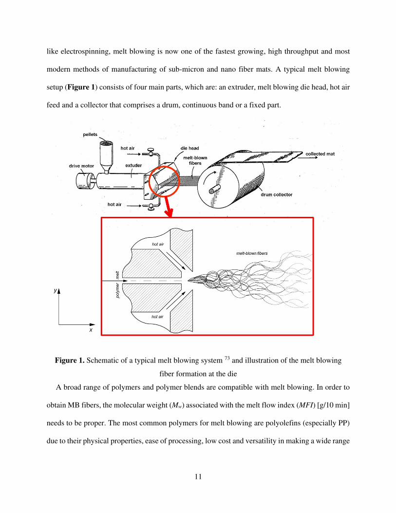
modern methods of manufacturing of sub-micron and nano fiber mats. A typical melt blowing
setup (Figure 1) consists of four main parts, which are: an extruder, melt blowing die head, hot air
feed and a collector that comprises a drum, continuous band or a fixed part.
Figure 1. Schematic of a typical melt blowing system 73 and illustration of the melt blowing
fiber formation at the die
A broad range of polymers and polymer blends are compatible with melt blowing. In order to
obtain MB fibers, the molecular weight (Mw) associated with the melt flow index (MFI) [g/10 min]
needs to be proper. The most common polymers for melt blowing are polyolefins (especially PP)
due to their physical properties, ease of processing, low cost and versatility in making a wide range
Page 13
12
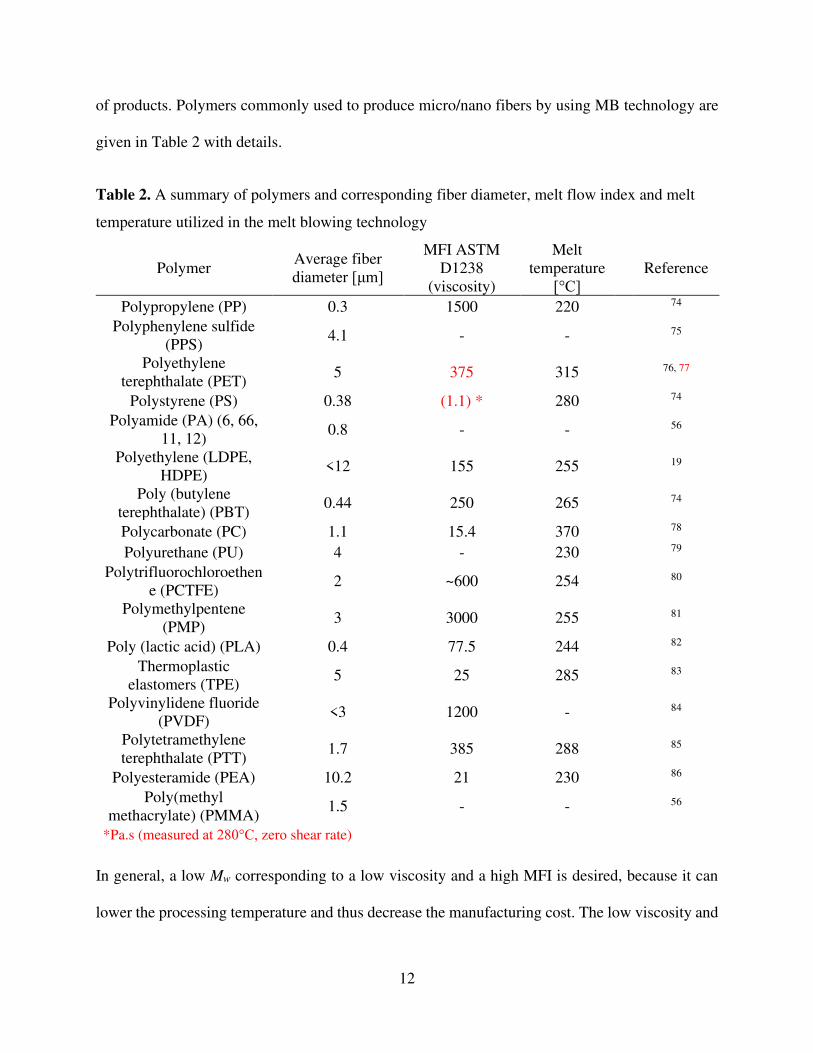
of products. Polymers commonly used to produce micro/nano fibers by using MB technology are
given in Table 2 with details.
Table 2. A summary of polymers and corresponding fiber diameter, melt flow index and melt
temperature utilized in the melt blowing technology
Polymer Average fiber
diameter [μm]
MFI ASTM
D1238
(viscosity)
Melt
temperature
[°C] Reference
Polypropylene (PP) 0.3 1500 220 74
Polyphenylene sulfide
(PPS) 4.1 - - 75
Polyethylene
terephthalate (PET) 5 375 315 76, 77
Polystyrene (PS) 0.38 (1.1) * 280 74
Polyamide (PA) (6, 66,
11, 12) 0.8 - - 56
Polyethylene (LDPE,
HDPE) <12 155 255 19
Poly (butylene
terephthalate) (PBT) 0.44 250 265 74
Polycarbonate (PC) 1.1 15.4 370 78
Polyurethane (PU) 4 - 230 79
Polytrifluorochloroethen
e (PCTFE) 2 ~600 254 80
Polymethylpentene
(PMP) 3 3000 255 81
Poly (lactic acid) (PLA) 0.4 77.5 244 82
Thermoplastic
elastomers (TPE) 5 25 285 83
Polyvinylidene fluoride
(PVDF) <3 1200 - 84
Polytetramethylene
terephthalate (PTT) 1.7 385 288 85
Polyesteramide (PEA) 10.2 21 230 86
Poly(methyl
methacrylate) (PMMA) 1.5 - - 56
*Pa.s (measured at 280°C, zero shear rate)
In general, a low Mw corresponding to a low viscosity and a high MFI is desired, because it can
lower the processing temperature and thus decrease the manufacturing cost. The low viscosity and
Page 14
13
high MFI provide a more uniform web with thinner fibers in the melt blowing process due to higher
attenuation applied through hot air steam. In the literature, it is suggested that the suitable range
of MFI for polymers used in melt blowing is 15-3,000 g/10 min 4, 56, 87, 88 as a rule of a thumb. The
high polymer viscosity and i.e. low MFI yields formation of larger fibers; hence, the advantage of
the process in forming ultra-fine fibers is lost 87. Besides, the average Mw and the narrow molecular
weight distribution is important to obtain MB fibers. The melt flow rate of the polymeric resins
depends upon the molecular weight and its distribution. The narrower molecular weight
distribution renders a high melt flow rate. Lower viscosity is an essential requirement of the
polymeric resins used in melt blowing. A narrow molecular weight distribution reduces the melt
elasticity and melt strength of the polymer so that the melt stream can be drawn into fine fibers
without excessive draw force 88, 89. However, a wide molecular weight distribution increases melt
elasticity and melt strength and result in fiber breaks and flaws due to melt instabilities 4, 74. The
decrease in elongation causes the increase in fiber diameter and fewer fiber entanglements. Tan et.
al. 90 reported that increasing melt elasticity increased the fiber diameter and decreased the
coefficient of variation (CV) (also known as normalized width of the fiber diameter distribution)
while increasing viscosity did not significantly affect the CV. Drabek and Zatloukal 91 reported
that polymer molecules chain branching could lower the CV of fiber diameter distribution, while
they stated chain branching did not significantly influence the average fiber diameter. In general,
decreasing molecular weight or increasing melt temperature increases (e.g., due to the decreasing
reptation-mode relaxation time) the CV of fiber diameter distribution. They also found that the CV
of fiber diameter distribution significantly decreases due to the extensional strain hardening at the
post die zone 92. They stated that increased strain hardening in uniaxial extension at post die zone
Page 15
14
could withstand inhomogeneous stretching in the post-die area, which reduces CV of fiber
diameter distribution.
A measure of the breadth of the molecular weight distribution is given by the ratios of
molecular weight and number mass averages (𝑀𝑤𝑀𝑛), called the polydispersity index (PDI). Jones 93
studied the influence of polydispersity on the mechanical characteristics of polypropylene (PP)
MB webs. The mechanical properties of PP MB webs are slightly affected by the changes in PDI.
The strength of web decreases with the increasing degrees of PDI.
3. Processing Parameters Affecting the Fiber Mat Characteristics and Filtration
Efficiency
Considering engineering and medical applications, MB fiber mats provide advantages of high
filtration efficiency and low air resistance besides many other advantages 6, 94, 95. Thanks to the
very high surface area to volume ratio, highly porous structure with moderate mechanical strength,
and the high surface cohesion, the MB fiber mat filters can capture tiny particles less than a micron.
Moreover, the filtration efficiency can be improved further with optimizing processing parameters
based on the requirements that can go up to less than 0.3 µm.
The filtration efficiency of the MB fiber mats highly depends on the processing parameters
which directly relates the structure (e.g., fineness and evenness), pore size, strength, fiber diameter,
thickness (packing density) and the air permeability (resistance) across the filter. The diameters of
polymeric fibers can be drawn in the high-speed hot air in the range from nanometers to
micrometers if appropriate parameters of the process are maintained. The MB fibers are
susceptible to the processing parameters set, and they can either improve or drop the nonwoven
Page 16
15
characteristics. Therefore, examining the suitable processing parameters is necessary for the MB
fiber mat to fulfill the requirements of the related application field.
3.1. Polymer throughput rate
The polymer flow rate plays key roles in the resulting diameters of MB fibers. The polymer
flow rate (throughput) at a given setup can be increased by increasing the extruder screw speed.
Increasing polymer throughput rate while keeping the other processing conditions unchanged
results in an increase in the average fiber diameter 96. It is because the same drag force from the
air jet acts on a higher polymer mass. In general, increasing polymer flow rate can increase the
fiber diameter and that in turn gives a coarser fiber morphology and decrease of quality of the MB
fiber mat. Zhang et. al. 97 found that increasing polymer throughput rate from 03 g/h/m to 1.5
g/h/m increased the Poly (trimethylene terephthalate) (PTT) MB fiber diameter around 20%.
Xu and Wang 95 reported that air permeability, fiber diameter, area density and surface density
unevenness of PP fiber mats increases with increasing the polymer throughput rate. They stated
that increase in the air permeability is due to the increased fiber diameter and it leads to big pore
sizes between the fibers, therefore it results in a good air permeability of the PP fiber mats.
Typically for MB fiber mats with all the other conditions being same, increasing polymer
throughput rate tends to increase fiber diameter and obviously the areal density. Increasing the
throughput rate causes broader fiber diameter distributions and a coarse fiber morphology (e.g.
defect formation, larger pores and larger basis weight), which is unfavorable 98, 99. Guo et. al.100
demonstrated that increasing polymer throughput rate increases PP (MFI= 1200 g/10 min
@230 °C, 2.16 kg) fiber diameter from 3 to 10.5 µm while porosity and surface are decreases from
90% to 75% and 1.5 m2/g to 0.5 m2/g (Figure 2).
Page 17
16
Figure 2. Influence of polymer throughput rate on PP fiber mat porosity and surface area and
average fiber diameter 100
Marla and Shambaugh 101 concluded that lower polymer flow rates results in smaller fibers that
causes the rapid cooling of MB isotactic polypropylene (iPP) fibers (MFI= 88 g/10 min @230 °C,
2.16 kg). It is because of the lower thermal inertia of the thinner fibers increases the cooling rate.
On the other hand, a lower polymer feed rate provides longer residence time in the extruder, which
might cause the thermal degradation of the polymer. Nevertheless, various research groups
reported that a decrease in the polymer flow rate leads to obtaining thinner fibers 96, 102
3.2. Air Pressure (Air flow rate or Air velocity)
Air pressure and air velocity, which are related to the air flow rate, influence the morphology.
In melt blowing, a higher air velocity results in a higher attenuation and a smaller fiber diameter.
The compressed hot air used in melt blowing was revealed to be the major energy cost. Using very
high air velocity might result in a fiber break up and short, fragmented fibers. And this defect is
often called fly. It occurs because of the strong cooling effect on the thinned fibers 81. In contrary,
at too low air velocities, the polymer mostly would not form a fibrous mat but would fuse into a
film-like body on the collector 103. The increase of the air velocity, usually achieved by increasing
Page 18
17
the air pressure, can break up fibers and generate fiber loose. It was reported that such instabilities
cause the fiber jet break by the increase of air pressure. 74. Drabek and Zatloukal104 summarized
these flow instabilities and defect formation mechanisms at the melt blowing process. We refer the
reader to their study for an in-depth understanding of such phenomenon, including whipping, die
drool, onset fiber breakup, melt spraying, flies, shots, jam, etc.
Yeşil 105 reported that increasing air pressure decreases the basis weight and air permeability
of TPU MB fiber mats (Figure 3 (a)-(b)). Decreasing basis weight can be associated with the
reduced fiber diameter with increased air drawing rate. In general, the lower air permeability
translates to higher filtration efficiency, which means less particle and fluid to pass through the
filtering media. Besides, he reported that tear strength decreased with increasing air pressure
(Figure 3 (c)) due to the air quenching, which reduces fiber to fiber bond strength.
Figure 3. Effect of air pressure on the MB fiber mat (a) basis weight, (b) air permeability and (c)
tear strength (DCD: die-to-collector distance)105
Page 19
18
Milligan and Haynes 106 worked on melt blowing of a different types of PP (MFI varied between
500-900 g/10 min @230 °C, 2.16 kg). They reported that a ratio of air to polymer mass fluxes (Γ)
provides an approximate description of the fiber size for a wide range of processing conditions
(Eqs. 3). They found that increasing Γ results in a decrease in the average fiber diameter of the MB
fiber, as shown in Figure 4.
𝛤 = �̇�𝑎 𝐴𝑎𝑒⁄�̇�𝑝 𝐴𝑝𝑒⁄ (3)
where, �̇�𝑎 is the air flow rate [m3/s], 𝐴𝑎𝑒 is the air outlet area [m2], �̇�𝑝 is the polymer flow rate
[m3/s] and 𝐴𝑝𝑒 is the polymer melt outlet area [m2]. On the other hand, increasing Γ broadens the
fiber diameter distribution’s CV due to the increase in the turbulence of the air flow field. But, the
fluctuation of air flow (turbulence) can decrease the evenness of the MB fiber mat 107.
Figure 4. (a) The effect of polymer flow rate on fiber attenuation 101and (b) the average fiber
diameter versus air to mass ratio for three throughputs 106
Higher air velocity attenuates the fibers more since the air exerts a higher forwarding drag force
on the fibers. Uppal et al. 108 reported that the average diameter of the PP fibers produced by melt
Page 20
19
blowing pilot line reduced by about 70 nm (from 590 nm to 520 nm) with the increase of air flow
pressure from 70 to 140 kPa in the case of the die used. Milligan et al. 109 worked on the influence
of an additional unheated air flow namely crossflow on the MB fiber morphology. They used two
crossflow chambers placed parallel next to the melt blowing die. In their study, the influence of
various crossflow angle, which is between spinline and slit (e.g.,45°, 20°, 10°), were
investigated. They concluded that applying a crossflow can decrease the average fiber diameter of
MB hPP (MFI= 800 g/10 min @230 °C, 2.16 kg) fibers around 45% (from ~11 μm to ~6 μm)
when the slit angle was 20°. Xie et al. 107 concluded that the air velocity attenuates the fibers in
their molten state. Otherwise, there is no contribution of high air velocity to fiber attenuation after
the fiber solidified. Therefore, the further increase in air velocity can cool the fiber faster and
hence, the attenuation process slows.
However, higher air pressure can translate air flow regime from laminar to turbulence, and
further increasing air velocity could increase the CV of fiber diameter, which is unfavorable 110,
111. Tan et. al. 90 reported that increasing airflow rate from ~147 l/min to ~272 l/min increased the
CV of fiber diameter from 10% to 20% while the fiber diameter decreased around 40%. Choi et
al. 112 found that the stiffness of the different grade homopolypropylene (hPP) (MFI= 300-35-12.7
g/10 min @230 °C, 2.16 kg) MB fiber webs decreased as the air pressure increased. They also
reported that increase in the air pressure causes a reduction in both fiber diameter and inter filament
(fiber fuse) bonding.
The hydrostatic head is another factor: the measure of fiber mat resistance against the liquid
pressure. When the fiber mat hydrostatic head is high, it translates to a greater barrier to liquid
penetration. With this regard, a high hydrostatic head means small pores and thin fibers in the fiber
mat structure, indicating favorable physical properties. Yesil and Bhat39 found that when the air
Page 21
20
pressure is increased from 20 to 35 kPa, the mean flow pore diameter and air permeability decrease,
and they reported the reduction could be attributed to the fiber diameter (Figure 5) that also
decreases with increasing air pressure. However, they did not find a significant change in air
permeability and mean pore diameter for the further increase in air pressure. In addition to these,
increasing air pressure from 20 to 35 kPa resulted in the increasing of the hydrostatic head of fiber
mats in a range between 54 and 97%. And they reported a slight decrease in the hydrostatic head
with a further increase in air pressure. Decrease in the average pore size translates the increasing
resistance of the fiber mat against fluids, so the penetration or passing of the fluid through the fiber
mat media becomes hindered. As a result, the hydrostatic head of the fiber mat was increased.
Figure 5. SEM images of PE MB fiber mats produced at various air pressure; (a) 20 kPa, (b) 35
kPa, (c) 70 kPa (red-colored scale bars on the bottom left of the figures represent 20 µm) 5
Bresee et. al. 113 reported that increasing air pressure reduces the size and the number of pores
in MB fiber mats. Increasing air velocity also reduces the aspect ratio of pores. The reduction in
pore size is attributed to the decrease in fiber entanglements and to the reduced fiber diameter as
the airflow increases. Hammonds et. al. 82 studied the influence of air flow rate (i.e. air pressure)
and DCD on the pore size distribution of the PLA MB micro and nano fiber mats. They found that
increasing air flow rate and decreasing the DCD reduced the pore size of PLA fiber mat as shown
in Figure 6. They also reported that the tensile strength of the PLA microfiber and nanofiber mats
Page 22
21
increased with increasing airflow. Increased tensile strength of the PLA fiber mat is associated
with the preferred molecular orientation by large air attenuation and fiber orientation onto the
collector.
In general, MB fiber mat thickness decreases with increasing air pressure. A decrease in fiber
diameter with increasing air pressure results in longer collection times in order to achieve the same
basis weight. Long collection time translates more fibers and so thicker layers. With increasing air
pressure, this phenomenon causes decreasing mat thickness and makes smaller pores with higher
packing density 1, 82.
Figure 6. Variation of the mean pore size with respect to air flow rate and DCD 82
Tyagi and Shambaugh 114 studied oscillating (whipping) air jets to produce PP (MFI = 75 g/10
min @230 °C, 2.16 kg) fibers by melt blowing. They found that oscillating air jets resulted in finer
fibers than those produced by using the classical, steady air jets. The attenuation of molten fiber
jets in supersonic airflow created by a de Laval nozzle is effective for fine fiber production via
melt blowing 107. Tan et al. 115 studied the effect of increasing inlet air pressure in the melt blowing
die and the effect of a de Laval nozzle attached to the die face. Increasing air inlet pressure leads
to a transition from subsonic to the supersonic flow at inlet pressures greater than approximately
1 bar. However, they observed that the de Laval nozzle's use suppresses compression waves
Page 23
22
sourced by the unstable airflow field that causes defect formation (e.g. fly) up to certain air
pressure. The corresponding centerline air velocity increases with increasing air pressure until
reaching supersonic flow where the fiber spinline begins to oscillate. This phenomenon can lead
to defects and probably significant whipping of the fiber jet. Violent vibrations can cause fiber
breakage, shots and sticking 74. However, Xie et al. 116 reported that the spiral path of whipping
close to the die plays an important role in fiber attenuation. In general, increasing the air velocity
can reduce the average MB fiber diameter. But it has not been favored by industries since it
significantly increases the cost of production.
The air pressure controls the fiber attenuation mechanism, the entanglements, the uniformity
and also influences the defects of the fiber mats 117. Besides, the higher air velocity can lead to
faster cooling of the forming fibers. A slight decrease in the crystalline fraction of the MB fibers
is expected in the case of semi-crystalline polymers due to the rapid cooling of the polymeric fibers
as a nature of the melt blowing techniques 76, 118. Higher air pressures were mostly suggested in
the literature to achieve thinner fibers. However, air pressure has to be carefully controlled since
higher air velocity can cause breakage of the spin-line and result in shot, fly imperfection and
relatively larger fiber diameters due to fiber fuse 119.
3.3.The Effect of Melt and Air Temperature
Increasing air temperature and melt temperature leads to a reduced polymer viscosity which
increases the attenuation. The air drag generates a higher stretching on the polymer between the
processing temperature and the solidification temperature (crystallization temperature for semi-
crystalline polymers that are typically used at melt blowing). In general, the higher temperatures
are not favorable in melt blowing with respect to the degradation of the polymer. In this regard,
Drabek et. al.120 reported that an hour of residence time at the processing temperature (combined
Page 24
23
with medium high shear rate level) resulted in nearly 40% decrease in the PP resin’s (MFI = 1200
g/10 min at 230 °C, 2.16 kg) molecular weight due to chain scission. Lee and Wadsworth 121
demonstrated that increasing the air temperature from roughly 210 °C to 240 °C led to a nearly
50% reduction in the average fiber diameter of iPP (MFI = 700 g/10 min @230 °C, 2.16 kg), where
the smallest fiber diameter they obtained was around 5 μm.
Bansal and Shambaugh 102 carried out a series of melt blowing experiments of PP (MFI = 75
g/10 min @230 °C, 2.16 kg) at different air temperatures with an experimental melt blowing slot
die. Their results show that increasing the air temperature causes an increase in the attenuation rate
of the fiber and produces a finer fiber (71.7 µm → 62.5 µm) as shown in Figure 7. Guo et. al. 100
investigated the relationship between the melt blowing process parameters and the PP fiber mat
structure. They reported that the porosity of the PP fiber mat did not change with increasing air
temperature from 300 to 330 °C in spite of the finding that increasing air temperature resulted in
decreasing the average fiber diameter. On the other hand, Xie et al. 107, 122 reported that higher air
temperature does not always produce fine fibers with even diameter distribution. They obtained
that increasing temperature might cause thicker fibers and defect formation due to the turbulent
flow by increasing air temperature. Besides, the air cools down very fast when it exits the die due
to the low ambient temperature. This effect depends on the polymer melting temperature and the
air-fiber temperature gradient towards the collector. Air temperature usually just slightly
influences fiber morphology for high DCDs, in many cases its effect on the fiber diameter is
negligible.
Page 25
24
Figure 7. Change in fiber diameter as a function of DCD with air temperatures between 315-330
°C 102
Moore et al. 123 reported that the temperature of the melt blowing die (and therefore the melt)
plays a crucial role in the fiber attenuation and affects the fiber diameters and pore sizes
significantly. They found that increasing the die temperature from 250 °C to 300 °C decreases the
average fiber diameter of the MB fibers around 50% (from 12 to 6 μm). On the other hand, Marla
and Shambaugh 101 reported that the further increase in polymer temperature would result only in
a slight decrease in the fiber diameter.
Yesil and Bhat 5 studied the influence of the die temperature on PE (MFI = 155 g/10 min @190
°C, 2.16 kg) fiber mat’s porosity and barrier properties. They reported that the mean pore diameter
of the MB fiber mats produced at 255 °C is slightly lower (~15%) than those processed at 240 °C.
However, they found that the effect of the die temperature on the air permeability is negligible. In
the same study, the hydrostatic head of PE fiber mat increased by increasing the die temperature.
The higher die temperatures not only result in smaller pore diameter and higher hydrostatic head,
but also finer fibers were obtained. However, Xu and Wang 95 reported that in the case of PP,
increasing air temperature from 170 °C to 230 °C decreases air permeability from 1054 mm/s to
Page 26
25
689 mm/s. This improvement is attributed to that finer fibers were produced at higher
temperatures. During melt blowing non-isothermal crystallization occurs due to the large
temperature difference between the die and ambient temperature. Lower crystallinity is expected
due to rapid cooling, which causes reduced polymer chain segment motions. Therefore, the
collected MB fibers exhibit relatively low crystallinity due to the effect of quenching 82.
There are no reports on achieving greatly thinner fibers by simply increasing polymer or air
temperature which is possibly because of the risk that high temperature is likely to cause thermal
degradation. Nevertheless, the high temperatures can be considered for producing fine fibers as
long as the extra production expenses are acceptable, and there is no oxidation of the polymer
occur and no defect formed e.g., fiber fuse, fiber breakage, shot, fly, etc.
3.4.The Effect of Die-to-Collector Distance (DCD)
The die-to-collector distance (DCD) influences the fiber diameters since it correlates with the
dwell time of the fiber attenuation. This results in changes in both the aerodynamic drag and fiber-
fiber entanglements and their fused bonds. Besides, as fiber jet travels along the collector the
molecules become oriented 124. The typical DCD at melt blowing is in between 50 - 500 mm.
The DCD can have various effects depending on the material due to the intrinsic properties,
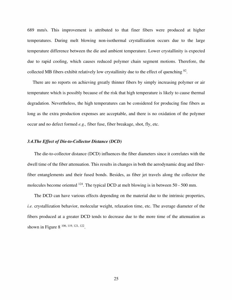
i.e. crystallization behavior, molecular weight, relaxation time, etc. The average diameter of the
fibers produced at a greater DCD tends to decrease due to the more time of the attenuation as
shown in Figure 8 106, 119, 121, 122.
Page 27
26
Figure 8. Optical microscopic images of PP MB fibers produced at (a) DCD = 25 mm and (b)
DCD = 50 mm 122
Increasing DCD translates the fibers travel longer distances, and that might result in an altered
crystallization kinetics, e.g. change in the degree of crystallinity. However, higher DCDs may
result in diminished interfiber adhesion and web strength originating from the lower fiber contact
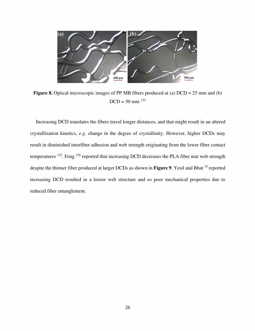
temperatures 125. Feng 126 reported that increasing DCD decreases the PLA fiber mat web strength
despite the thinner fiber produced at larger DCDs as shown in Figure 9. Yesil and Bhat 19 reported
increasing DCD resulted in a looser web structure and so poor mechanical properties due to
reduced fiber entanglement.
Page 28
27
Figure 9. SEM images at DCD of (a) 75mm, (b),100mm (c) 200mm and (d) stress–strain curve
of the PLA fiber mats collected at various DCDs 126
Increasing DCD results in fiber collection over a wider area. It also results in a softer, fluffier
structure, so increasing DCD decreased fiber mat solidity 95, 127. The effect of the increased
deposition area is smaller than the effect of decreased fiber mat solidity and that results in a thicker
fiber mat. The mat thickness correlates to the packing density, which is a crucial factor in
determining the pore size. Denser fiber packing can be reached with a thicker layer of fibers that
will result in higher efficiency of the filter 42, 128 with an increased pressure drop. Therefore, the
mat thickness and packing density has to be optimized and DCD is the key parameter in that.
Slightly finer fibers at higher DCD can be obtained due to the deformation of hot uncrystallized
fibers 108. Chen et al. 129 obtained that PBT (MFI = 62 g/10 min @ 250°C, 2.16 kg) fiber diameter
decreases 13% as the DCD increase from 100 to 140 mm. However, they reported that the fiber
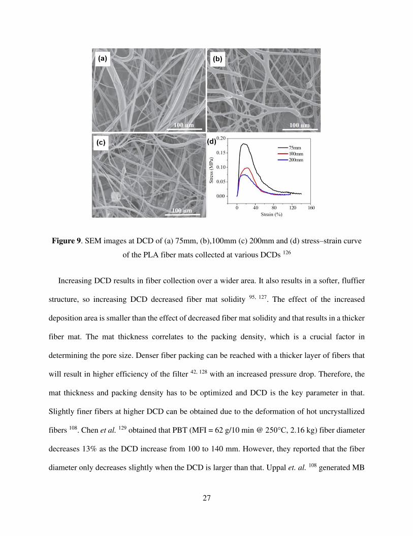
diameter only decreases slightly when the DCD is larger than that. Uppal et. al. 108 generated MB
Page 29
28
PP fibers and investigated the influence of relatively large DCD (250 mm to 350 mm) on the fiber
mat characteristics. They produced PP fiber mat samples with the same basis weight (~25 𝑔/𝑚2)
while the mat thickness increased from 0.44 mm to 0.53 mm with increasing DCD. They found
that the pore diameter decreases from 10.4 μm to 6.5 μm with an increase of DCD from 250 to 350
mm while the fiber diameter and air permeability of the fiber mats decrease slightly. The reduced
pore size is related to a higher degree of fiber entanglement. This is because of the improved self-
bonding of the thinner and continuous MB fibers produced for the same basis weight. As a
consequence, the resistance to the penetration of liquid through the MB fiber filter media increases,
and that in turn increases hydrodynamic head as shown in Figure 10. The pressure drop of the
filter media first increased from 49 Pa to 55 Pa with increasing DCD then it became constant due
to reduced pore size. However, the filtration efficiency is slightly improved from 80% to 82% due
to the smaller pore size as well as greater specific surface area of the finer fibers produced at higher
DCD. The slight increase of these properties indicates smaller pores, greater specific surface area
of the thin and continuous fibers and higher degree of fiber entanglements.
Figure 10. Influence of DCD on the PP web (a) pore size and (b) hydrostatic head characteristics
108
Choi et al. 112 reported that increasing DCD improves tenacity and decreases Young’s modulus
of hPP (MFI= 300-35-12.7 g/10 min @230 °C, 2.16 kg) fiber mats and results in increased
Page 30
29
elongation at break. Besides, they found that an increase in DCD reduces the bonding of the fibers
(fuses) without much effect on the fiber diameter. Bresee and Qureshi 130 studied the effect of DCD
on the diameter MB PP (MFI = 1,259 g/10 min @230 °C, 2.16 kg) fibers with commercial and
experimental melt blowing lines. They found that the average fiber diameter decreases with the
increase of DCD, but the influence is very weak. The average fiber diameter reduced by nearly
11% for the experimental line and 15 % for the commercial line with 600 mm increase of DCD
from 200 to 800 mm. They also stated that the maximum fiber diameter and its CV increase with
the increase of DCD due to the fusion of fibers.
In another study, Bo 131 reported that upon increasing DCD the diameter of PP (MFI = 34.2
g/10 min @ 230°C, 2.16 kg) fibers first decreases and the attenuation stops in a certain DCD and
the diameters starts increasing again (Figure 11). He stated that after this point, long time travelled
fibers begin severely entangled and stick to each other and that in turn gives an increase in fiber
diameter and uneven structure for very long DCDs (above 1000 mm).
Figure 11. Change in fiber diameter respect to very high DCDs 119
Page 31
30
Lee and Wadsworth 121 studied the influence of processing parameters on melt blowing of iPP
(MFI = 700 g/10 min @ 230°C, 2.16 kg). They reported that decreasing DCD increases the degree
of fiber entanglements but does not affect the average fiber diameter. On the other hand, as the
DCD increases the fibers are laid down with less air drag force and the effect of air pressure is
reduced. Also, air turbulence is high at the collector drum and longer DCDs allow the fibers to be
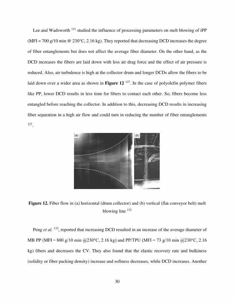
laid down over a wider area as shown in Figure 12 127. In the case of polyolefin polymer fibers
like PP, lower DCD results in less time for fibers to contact each other. So, fibers become less
entangled before reaching the collector. In addition to this, decreasing DCD results in increasing
fiber separation in a high air flow and could turn in reducing the number of fiber entanglements
127.
Figure 12. Fiber flow in (a) horizontal (drum collector) and (b) vertical (flat conveyor belt) melt
blowing line 132
Peng et al. 133, reported that increasing DCD resulted in an increase of the average diameter of
MB PP (MFI = 800 g/10 min @230°C, 2.16 kg) and PP/TPU (MFI = 73 g/10 min @230°C, 2.16
kg) fibers and decreases the CV. They also found that the elastic recovery rate and bulkiness
(solidity or fiber packing density) increase and softness decreases, while DCD increases. Another
Page 32
31
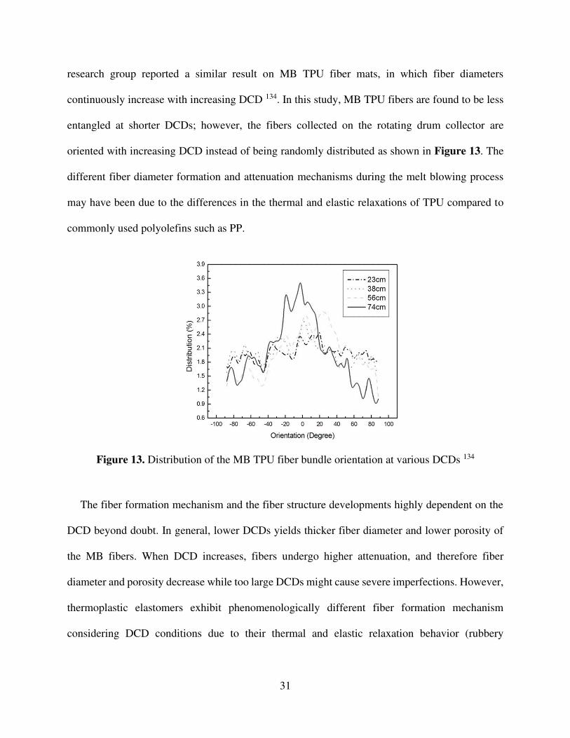
research group reported a similar result on MB TPU fiber mats, in which fiber diameters
continuously increase with increasing DCD 134. In this study, MB TPU fibers are found to be less
entangled at shorter DCDs; however, the fibers collected on the rotating drum collector are
oriented with increasing DCD instead of being randomly distributed as shown in Figure 13. The
different fiber diameter formation and attenuation mechanisms during the melt blowing process
may have been due to the differences in the thermal and elastic relaxations of TPU compared to
commonly used polyolefins such as PP.
Figure 13. Distribution of the MB TPU fiber bundle orientation at various DCDs 134
The fiber formation mechanism and the fiber structure developments highly dependent on the
DCD beyond doubt. In general, lower DCDs yields thicker fiber diameter and lower porosity of
the MB fibers. When DCD increases, fibers undergo higher attenuation, and therefore fiber
diameter and porosity decrease while too large DCDs might cause severe imperfections. However,
thermoplastic elastomers exhibit phenomenologically different fiber formation mechanism
considering DCD conditions due to their thermal and elastic relaxation behavior (rubbery
Page 33
32
characteristics). Consequently, the structure and properties of MB fiber mats can be controlled and
optimized through DCD.
4. Developments of filter media made of MB nano/microfibers for filtration
The outbreak of the coronavirus (COVID-19) pandemic revealed that respiratory protection
plays a vital role in the present world and the development of ultrafine polymeric fiber mats highly
efficient filters allowing filtration of a wide range of particles, viruses, and aerosol is necessary 135,
136. MB filters are the classic filtration media of good-quality masks, independent from the
pandemic. Bioaerosols that are living or originate from living organisms might include
microorganisms and fragments, toxins, and particulate waste from all varieties of living bodies 137.
These biologically hazardous substances or bioaerosols might be transferred through the air, and
they could cause severe health effects because of their ability to incubate, grow, multiply, and
produce toxic substances 138. The efficient inhaled air filtration and cleaning off such hazardous
particles, as well as the destruction of the inhibition of that bioaerosol development, are the matter
of respiratory protection systems made of nonwovens filters. Many particulate respirators use a
filter media made of MB fiber mats to capture these types of particles. We summarized the MB
fiber mats and related properties in Table 3 reported for high-efficiency fiber mats produced via
melt blowing technology.
Table 3. Some essential filtration properties of MB fiber mat filter medias reported in the
literature
Material
Average
fiber
diameter
[µm]
Average
pore size
[µm] Porosity
[%]
Pressure
drop [Pa]
(loading
speed)
Filtration
efficiency
[%]
Reference
PP 0.55 6.5 N/A 54.9 (32
L/min) 81.9 108
Page 34
33
PP 2.8 N/A 85.6 55.9 (0.053
m/s) 88.6 139
PP 2.4 9.3 N/A 37.4 95.91 46
2 layers PP
MB + 3 layers
PP Needle
Punched (NP)
2.07 (MB) 15.5 (MB)
N/A 136.87 (85
L/min) 99.52 140
17.9 (NP) 70.1 (NP)
PP 0.47 N/A N/A 20.27 (0.05
m/s) 91.19 141
0.5 wt% MgSt
additive PP 1.63 ~15 89.3
82.32 (85
L/min) 99.03 142
1 wt% MgSt
additive PP ~2 14.2 90.1
53.1 (85
L/min) 92.57 143
PP MB +
PVA ES 0.208 N/A N/A
34 (3.4
m3/h) 96.5 144
PP / PS 3 ~9 ~90 37.73 (32
L/ min) 99.87 94
Spunbond
(PET/PE) / +
TiO2/Ag
additive MB
PP
4-16 3.3-3.8 N/A ~80 (85 L/
min) ~ 95 52
PP 2.64 ~17 N/A
22.45
(0.053 m/s)
@50 °C
98.46
145 19.45
(0.053 m/s)
@110 °C
~60
PP 2.1 11.2 89 120 (0.141
m/s) 99.65 146
PP / PEG 1-6 N/A 88 55.53
(0.053 m/s) 85.33 147
PP 1–2 3-14 89.94 38.7 (32
L/min) 98.35 8
10 %wt
BaTiO3
additive PP
~3 N/A 65 95 (0.053
m/s) 99.97 148
3 wt% TiO2
additive PP 6.73 N/A N/A
40 (85 L/
min) 96.32 149
PP / PC 0.63 N/A N/A 59 (3.4
m3/h) 95.9 150
Page 35
34
PLA 0.1–3.0 N/A N/A 40.8 (0.053
m/s) 88.5 151
PLA / PCL 3.3 N/A N/A N/A (0.053
m/s) 95 152
PLA 3.1 N/A 88.5 38.2 (0.053
m/s) 93.2 139
In order to fulfill various requirements considering an efficient filtration, multi-layer or
laminated filtering systems are preferred, in which every layer meets different tasks. The MB fiber
mats are often used as stacks that consists of several layers of the separate fiber mats and stacking
of layers with another woven or nonwoven or a film 153, 154. The additional layer for the filter is
selected to impart additional or complementary properties to fulfill required features, such as tear
resistance, strength, biocompatibility, air permeability and filtration properties. The laminated
structures are highly suitable not only for respiratory devices but also for various application field
including protective garments, drapes, medical gowns, covers for diapers, adult care products,
sanitary napkins, etc. 155.
Roh et. al. 156 prepared and tested the filtration efficiency of multi-layered nonwoven filters
made of electret PP MB fiber mat and PET nonwoven to lower the pressure drop, improve the
quality and extend the service life for various filtration application. In their study, various filters
were constructed with and without an air gap between the layers either by inserting a 5 mm thick
acrylic plate (Air gap) or 5.5 mm thick-spacer web (S-gap) (Figure 14). The pressure drop across
the filter media is a function of the particle loading speed; when loading speed increases, pressure
drop increases. They reported that pressure drop decreases dramatically with NaCI particle loading
when the air gap is inserted between layers. The designed air gap acted as the active flow channel
between fiber mat stacks. However, the pressure drop with the loading did not effectively reduce
Page 36
35
even increased for the tested the two layers construction spacer web inserted filter because of the
thick spacer web inhibited airflow.
Figure 14. Schematic overview of the study (a) Filtering media layer construction, (b) Pressure
drops of different layer-constructions for face velocity of 15 cm/s, (c) computational model for
the pressure drop behavior of different stack and (d) Filter media morphology of different
constructions after NaCI aerosol loading 156
For the four-layer constructions, either the air gap or the spacer web insertion is found beneficial
in reducing the pressure drop. Even, the effect was more significant when the loading velocity
increased from 15 to 20 m/s. They obtained that spacer web insertion between the filter layers is
more effective in reducing the pressure drop compared to using bulk air gap. Results obtained by
the researchers showed that the inserted spacer web took place effectively distributing the airflow
and pressure drop over the filter media because the thick spacer web acted as a direct airflow
channel. A significant change in filtration efficiency and pressure drop occurs when the solid
particles are accumulated inside a fiber mat medium. The pores of the fiber mats could be clogged
with increasing pressure drop by the dendritic structure forming due to the captured solid particles.
This is related to the pressure drop development, which goes faster for the solid aerosol particles
Page 37
36
compared to the liquid aerosol of the filtering media 45. They reported that layered filter design
delays the clogging compared to the single layer MB fiber mats. However, increasing NaCI aerosol
particle loading velocity from 15 cm/s to 20 cm/s increased the pressure drop and resulted in faster
clogging of the filtering media. On the other hand, four-layered stacks showed promising results
that successfully lowered the pressure drop and increased the service life of filter media by
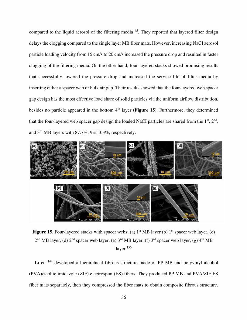
inserting either a spacer web or bulk air gap. Their results showed that the four-layered web spacer
gap design has the most effective load share of solid particles via the uniform airflow distribution,
besides no particle appeared in the bottom 4th layer (Figure 15). Furthermore, they determined
that the four-layered web spacer gap design the loaded NaCI particles are shared from the 1st, 2nd,
and 3rd MB layers with 87.7%, 9%, 3.3%, respectively.
Figure 15. Four-layered stacks with spacer webs; (a) 1st MB layer (b) 1st spacer web layer, (c)
2nd MB layer, (d) 2nd spacer web layer, (e) 3rd MB layer, (f) 3rd spacer web layer, (g) 4th MB
layer 156
Li et. 144 developed a hierarchical fibrous structure made of PP MB and polyvinyl alcohol
(PVA)/zeolite imidazole (ZIF) electrospun (ES) fibers. They produced PP MB and PVA/ZIF ES
fiber mats separately, then they compressed the fiber mats to obtain composite fibrous structure.
Page 38
37
The average fiber diameter of the hierarchical fibrous structure was around 0.209±0.058 µm in the
most successive case. They observed that the hierarchical PM2.5 filtration performance improved
to 96.5% while the pristine PP MB fiber mat had 21%. The hierarchical filter structure with finer
fibers effectively intercepts the particles to acquire better adsorption, resulting in improved
filtration efficiency. They also reported that composite filter media had higher tensile strength than
that of the pristine fiber mats. This is associated with high friction and good fiber adhesion between
the MB and ES fiber mats.
PP is the most widely used polymer for producing MB fiber mats 96 because of the fair
mechanical properties and cheap price. It is a non-polar polymer having a very large band gap
above 8 eV, which makes PP fiber mat a good electric insulator. This also makes PP less attractive
for capturing tiny particles that is clearly a disadvantage. Admixing various charge enhancer
additives (e.g., barium titanate, stearate, calcium carbonate, etc.) are suggested to overcome this
issue and hence improve the filtration performance 148, 157. In addition, environmental conditions
(e.g., air humidity, moisture) and applied decontamination methods (e.g., sanitizing with alcohol)
may favor the degradation of the charge that reduces filtration performance 158. Therefore, the
ability to maintain charges is fundamental for various in-use scenarios such as in respiratory
protective devices 27. Electrostatic charging is frequently applied to nonwoven filters to enhance
their tendency to capture smaller microorganisms. This is typical for particles smaller than a
micron that can potentially penetrate into the respiratory system 159, 160. These systems involving
charged filter media are often called electret filters. Imparting electrostatic charge on the filter
medium has been successfully applied in the last three decades to the fiber mats to improve
filtration characteristics without compromising other properties (e.g., dimension and structure).
Particularly, the ionic species generated by the negative polarity through the corona-charging is
Page 39
38
proved to be an effective method to enhance filtration efficiency of MB PP fiber mats 160, 161.
Besides that, thermal preconditioning of the fiber mat may also enhance the static charge capacity
by maintaining fiber mat interaction with the humid ambient air 8.
The performance of an electret filter efficiency is related to its electrostatic decay time. The
filter media cannot capture small particles if the electrostatic capacity decays fast. Yang et al. 162
studied influence of corona discharge treatments on MB PP electret filters. They tested various
levels (10-25 kV) of surface voltages with different discharging times (2-10 minutes) applied at
room temperature (25 °C). They found that an increase in charging voltage and charging time
reduces the surface resistance, resulting in higher air permeability for efficient filtration. They also
reported that the MB fiber mat charged at 25 kV for 10 minutes maintains a high surface voltage
for two weeks. Time is a limiting factor in civil use but can be feasible in industrial applications.
Brochocka 163 produced PP (MFI: 800 g/10 min @230 °C, 2.16 kg) MB electret filters by the
addition of a superabsorbent polymer (SAP) with grain size of 250 μm and 30 μm. In the study,
MB electret fiber mats were manufactured. They used an in situ electrostatic activation device
cooperating melt blowing apparatus for the electrostatic charging of MB PP fibers. Besides the
melt blowing apparatus used in this study enabled introducing SAP into molten PP. the effect of
SAP grain sizes and electrostatic charge conditions (charged and non-charged) were tested
according to the requirements for respiratory protective devices (EN 149:2001+A1:2009 and EN
13274- 7:2008). The filtration efficiency of the charged fiber mats was found significantly higher
compared to the non-charged ones, but the grain size of SAP did not influence the filtration
efficiency. The MB fiber mats containing SAP absorbed air moisture performed much better than
those without SAP, which means a straightforward fiber making method can also contribute
potential applications in personal protective devices (e.g. hygienic products with fast absorption
Page 40
39
capability and storage of body fluids like urine, blood, etc.). The results show that partially
embedded grains of the modifier in PP MB fibers did not compromise significant changes in the
fiber structure (without hindering the functionality of the modifier). And electrostatic activation
led to the physical modification of fibers that, in turn, gave higher filtration efficiency. She proved
that MB fiber mat structures with high filtration efficiency designed for respiratory protective
devices can be produced in one technological process.
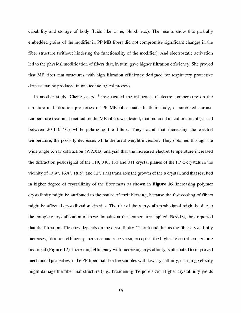
In another study, Cheng et. al. 8 investigated the influence of electret temperature on the
structure and filtration properties of PP MB fiber mats. In their study, a combined corona-
temperature treatment method on the MB fibers was tested, that included a heat treatment (varied
between 20-110 °C) while polarizing the filters. They found that increasing the electret
temperature, the porosity decreases while the areal weight increases. They obtained through the
wide-angle X-ray diffraction (WAXD) analysis that the increased electret temperature increased
the diffraction peak signal of the 110, 040, 130 and 041 crystal planes of the PP α-crystals in the
vicinity of 13.9°, 16.8°, 18.5°, and 22°. That translates the growth of the α crystal, and that resulted
in higher degree of crystallinity of the fiber mats as shown in Figure 16. Increasing polymer
crystallinity might be attributed to the nature of melt blowing, because the fast cooling of fibers
might be affected crystallization kinetics. The rise of the α crystal's peak signal might be due to
the complete crystallization of these domains at the temperature applied. Besides, they reported
that the filtration efficiency depends on the crystallinity. They found that as the fiber crystallinity
increases, filtration efficiency increases and vice versa, except at the highest electret temperature
treatment (Figure 17). Increasing efficiency with increasing crystallinity is attributed to improved
mechanical properties of the PP fiber mat. For the samples with low crystallinity, charging velocity
might damage the fiber mat structure (e.g., broadening the pore size). Higher crystallinity yields
Page 41
40
higher tensile strength. Increasing crystallinity might improve mechanical properties in general,
which gives a well-consolidated and robust filter media against the gas flow. The pressure drop
test also showed an increasing trend with increased electret temperature and so fiber crystallinity.
Therefore, the MB PP fiber mat’s filtration efficiency improved with increasing electret
temperature and fiber crystallinity against the NaCI charging with the applied constant velocity
(5.33 cm/s). On the other hand, the decrease in filtration efficiency is associated with decreasing
mat thickness for the highest electret temperature applied; however, no significant change
observed for the rest of the samples.
Figure 16. WAXD signals for various corona-temperature treated PP fiber mats 8
Page 42
41
Figure 17. Change in the crystallinity and filtration efficiency respect to the electret temperature
8
Kilic et. al. 148 compounded PP with various BaTiO3 concentrations (0.1, 1 and 10 %wt) to
enhance the performance of PP MB filters. In their study, BaTiO3 particles were dispersed
uniformly within the PP fibers without a compatibilizer. The average fiber diameter slightly
decreased with increasing BaTiO3 concentration (Figure 18). They heated the fiber mats at 130
°C and charged them at 9 kV for 10 minutes, and the filtration properties of the fiber mats were
tested with dioctyl phthalate (DOP) aerosols in 20-300 nm range at a velocity of 5.3 m/s. They
reported that thermal charging reduced DOP penetration from 14 to 7.3% in the case of 10%
BaTiO3 loaded PP MB fiber mats. They concluded that the applied method provides a filtration
efficiency of 99.97% for the 300 nm particle size, which stands for KN100 grade respiratory
protection devices. Besides that the efficiency of 10 min thermally charged 1% BaTiO3/PP sample
showed 90.8% filtration efficiency, whereas cold charged (without heat) exhibited 78.9% sample.
These results show that more uniform and effective charging occurred for heated and charged fiber
mats, resulting in higher filtration efficiency. On the other hand, their results showed that
increasing the BaTiO3 and thermal charging improved the polymer crystallinity and resulted in
effective charge stability and hance enhanced filtration efficiency .
Page 43
42
Figure 18. Change in MB fiber diameter and solidity versus BaTiO3 concentration 148
Zhang et. al. 143 reported that the addition of magnesium stearate (MgSt) to the PP melt
improved MB fiber mats crystallinity, their electrostatic potential, as well as the filtration
properties and the air permeability. They applied corona charging to further improve the filtration
efficiency of the composite fiber mats. In their study, they made a systematic comparison of the
filtration properties of the PP/MgSt fiber mat with a commercial MB fiber mat (PP, basis weight:
40 𝑔/𝑚2, daverage:1.98 µm, thickness:0.41 mm, porosity:89%) and a commercial electrospun fiber
mat (PAN, basis weight: 8.2 𝑔/𝑚2, daverage:0.36 µm, thickness:0.05 mm, porosity:86%). The
composite MB fiber mat (0.5 %wt MgSt additive PP) showed higher filtration efficiency against
solid particles with a better thermal and humidity stability than the commercial electrospun and
MB fiber mats (Figure 19 (a)-(e)). On the other hand, increasing basis weight means more fibers
in the filter media and that results in higher filtration efficiency; however, the developed composite
fiber mat with 40 g/m2 exhibited a filtration efficiency of 99% and a pressure drop less than 120
Pa, which stands for the FFP3 standard. The ratio of the negative natural log of penetration to the
pressure drop gives the quality factor, which describes the dynamic filtration performance of air
Page 44
43
filters. The quality factors of all samples decreased by increasing particle loading time. The
commercial electrospun and MB fiber mats showed lower quality factors upon increasing particle
loading time compared to the PP/MgSt fiber mats. On the other hand, the sharply declining trend
of the electrospun fibers in quality factor with increasing loading lied behind the pore size. The
authors concluded that the filter media having finer fibers with small pores led to forming a
dendritic structure and clogs the pores by longer loading times (Figure 19 (f)), which in turn gives
increasing pressure drop and therefore decrease the quality factor of the filter media. This results
showed that the developed composite fiber mat was characterized by excellent electrostatic
stability ensuring long storage and operating times.
Page 45
44
Figure 19. Filtration performance of the PP/MgSt MB fiber mat compared to the commercial
electrospun and MB fiber mats (a) Filtration efficiency versus various basis weights (air flow
rate of 85 L/min), (b) filtration efficiency versus various airflow rates, (c) the thermal stability of
the filtration efficiency (air flow rate of 85 L/min), (d) humidity stability of the filtration
efficiency (air flow rate of 85 L/min), (e) the quality factor respect to loading performance (air
flow rate of 85 L/min), (f) the SEM images of the PP/MgSt samples after the loading filtration
test 143
A limited supply good quality respirator during the COVID-19 pandemic revealed that existing
supply chains did not meet the surge in demand. This situation brought out a new route that paves
Page 46
45
the way for the re-use of respiratory protection devices. In general, such respirators are made to be
discarded after use. Re-using such respirators could significantly reduce the filtration performance,
and that causes severe health issues for the user. A case study done by Hossain et. al. 164 presented
an efficient way to maintain the filtration efficiency of used N95 respirators by re-charging the
filter media after a decontamination procedure. They tested the filtration efficiency of several
commercial masks supplied to hospitals made of PP MB fiber mats after sanitizing and re-charging
them. They sanitized a N95 respirator by dipping it in ethanol and dried overnight. In the first step,
they recharged the N95 respirator at 1 kV for 2,200 seconds and they obtained a filtration
efficiency of about 86%. After that they sanitized the mask again by spreading 1 ml ethanol on the
mask at the charging time of 3,125 seconds (measured filtration an efficiency of around 70%) and
finally they removed the sample from the tester at 4,500 seconds and dried it by a hot air steam at
50 °C. They reported that the applied method decreased the filtration efficiency to 50% (Figure
20 (a)) due to the pores blocked with residual alcohol. In these experiments they handled the
sample extensively by attaching and detaching the tester. In the second method, the edges of the
mask have been taped to prevent leakage from sides, and they applied in-situ recharging at 1,000V
for 9,000 seconds after the same sanitizing process. Finally, they obtained 90% filtration efficiency
by the in-situ recharging method (Figure 20 (b)). Their results showed that the filtration efficiency
of the respiratory devices made of PP MB fibers could somewhat recover by recharging the masks
after sterilization; that method makes it possible to re-use N95 masks.
Page 47
46
Figure 20. (a) Effect of 0.25 ml of ethanol on the filtering efficiency of the recharged
commercial N95 mask (b) Effect of 1kV voltage applied across in-situ recharged commercial
N95 mask 164
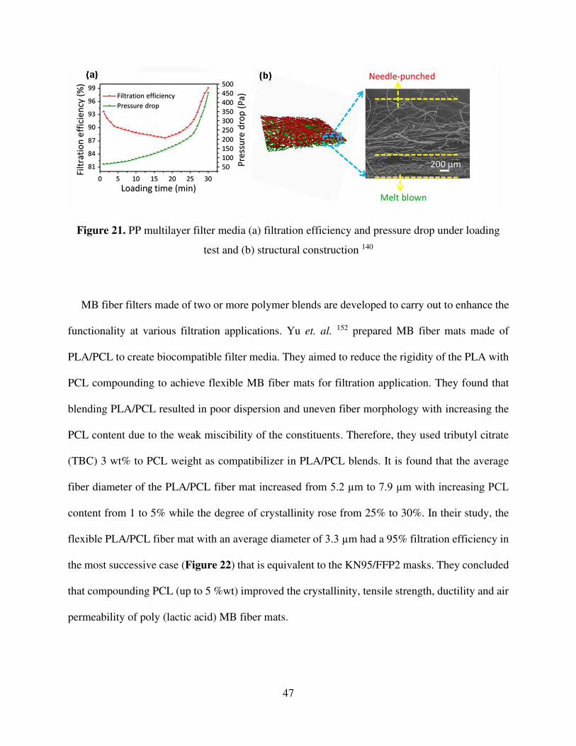
Zhang et. al. 140 developed a PP multilayer composite filter made of needle-punched layer
(NPL) and MB fiber mat layer (MBL) with a high filtration efficiency up to 99.52 ± 0.01% and a
low-pressure drop of 136.87 ± 0.49 Pa as shown in Figure 21. They reported that hierarchical
fibrous structure of 3 NPL / 2 MBL exhibited a dust holding capacity of 23.5 ± 0.41 g/m2. High
dust holding capacity translates a long service life for air filter. They observed that the multilayered
filter's dust holding capacity (3NPL/2 MBL) with a basis weight of 190 g/cm2 was also 3-fold
higher than individual needle-punched and MB fiber mats having a basis weight of 200 g/cm2 and
40 g/cm2, respectively.
Page 48
47
Figure 21. PP multilayer filter media (a) filtration efficiency and pressure drop under loading
test and (b) structural construction 140
MB fiber filters made of two or more polymer blends are developed to carry out to enhance the
functionality at various filtration applications. Yu et. al. 152 prepared MB fiber mats made of
PLA/PCL to create biocompatible filter media. They aimed to reduce the rigidity of the PLA with
PCL compounding to achieve flexible MB fiber mats for filtration application. They found that
blending PLA/PCL resulted in poor dispersion and uneven fiber morphology with increasing the
PCL content due to the weak miscibility of the constituents. Therefore, they used tributyl citrate
(TBC) 3 wt% to PCL weight as compatibilizer in PLA/PCL blends. It is found that the average
fiber diameter of the PLA/PCL fiber mat increased from 5.2 µm to 7.9 µm with increasing PCL
content from 1 to 5% while the degree of crystallinity rose from 25% to 30%. In their study, the
flexible PLA/PCL fiber mat with an average diameter of 3.3 µm had a 95% filtration efficiency in
the most successive case (Figure 22) that is equivalent to the KN95/FFP2 masks. They concluded
that compounding PCL (up to 5 %wt) improved the crystallinity, tensile strength, ductility and air
permeability of poly (lactic acid) MB fiber mats.
Page 49
48
Figure 22. SEM image of a PLA/PCL MB fiber mat with average diameter of 3.3 µm 152
Majchrzycka 165 developed a bioactived respiratory protection system made of PLA MB fiber
mats to achieve high filtration efficiency against bioaerosols. In her study, a biocide-bioperlite
(biocidal compounds harmless to human health) was prepared and applied to the fiber mats in
order to activate fibers against bioaerosols. Additionally, a corona discharge (with a discharge of
30 kV) was applied to the fiber mats to improve the bioaerosol filtration efficiency. She reported
that bioactivated electret PLA/bioperlite fiber mats achieved 99.34% and 99.26% filtration
efficiency against Staphylococcus Aureusand and Pseudomonas Aeruginosa bacteria, respectively.
However, the non-electrostatic activated PLA/bioperlite fiber mats exhibited 97.64% and 97.62%
filtration efficiencies against the same bacteria, which makes these filters in the class of FFP2.
They also obtained that the growth inhibition can be achieved for microorganisms (Staphylococcus
Aureusand and Pseudomonas Aeruginosa) during the time of incubation at a temperature of 37 °C
after 2 hours for the sample modified with bioperlite and electrostatically activated (Figure 23).
Their results showed that bioaerosol incubation properties of the MB filter media made of the
modified and electrostatically charged biocompatible polymers could be improved against without
sacrificing filtration properties.
Page 50
49
Figure 23. Results of tests on survival of (a) Staphylococcus aureus and (b) Pseudomonas
Aeruginosa respect to time (colored lines represent various fiber mat sample tested) 165
Zhu et al. 52 developed a high efficiency air filter by the incorporation of TiO2/Ag nanoparticles
into the composite nonwovens made of PET/PE spun-bonded (SB) - PP MB structure. They
reported that the exposed TiO2 nanoparticles on the fiber surface generated positive hole–negative
electron pairs to produce OH radicals and superoxide radical anion under UV light as shown in
Figure 24. The composite nonwoven filters achieved 99.07% and 99.27% antibacterial removal
rate under UV light against E. coli and S. aureus, respectively. On the other hand, pristine SB /
MB filter media without TiO2/Ag nanoparticles had less than 20% antibacterial removal rate with
and without UV treatment.
Page 51
50
Figure 24. Mechanism schematic of simultaneous effect of composite nonwoven filter media for
air pollutant removal and photocatalytic degradation of volatile organic compounds 52
5. Conclusion
Melt blowing consists of the extrusion of a polymer through small orifices in a die with drawing
of the extrudate by the aid of high-velocity hot air jets to generate continuous, fine polymeric fibers
in the form of a nonwoven. Melt blowing is the one of the most efficient methods to produce fiber
mats for filtering particulate matter, consisting of solid particles, liquid aerosol, and gas and vapor
compounds beyond a doubt. To date, both industry and academy put considerable effort into the
development of the MB fiber mats for the filtration applications. There are still many challenges
for further optimization, end-product designing, characterization, and process modeling in practice
despite the advances in the development of MB fiber mats for filtration implementation. Generally
speaking, mostly polyolefins and commodity thermoplastics resins are the raw materials of MB
products. Due to the fact that MB fibers process is often employed using polypropylene to
manufacture commercial fiber mats, especially producing filter media for widespread application
fields. The processing parameters is chosen to provide for filtration properties such as the fineness
and evenness, pore size, strength, fiber diameter, thickness and air permeability, whereas the
Page 52
51
materials are chosen to provide processability, strength, endurance and stability. The MB fiber
morphology is very sensitive to processing parameters such as melt and polymer temperature,
polymer throughput rate, air pressure, air temperature and die to collector distance (DCD). Fine
fibers, therefore, high filtration efficiency fiber mat with small pore sizes can be produced by
lowering the polymer throughput rate as long as all other parameters are the same. Increasing both
air and polymer temperature, fibers tend to be attenuated more and usually finer fibers can be
achieved by the reduced polymer viscosity. Besides, the crystallinity and orientation of the
polymeric fiber can be developed by the increasing temperature; besides the mechanical and
thermal properties of the fiber mat can be enhanced. Longer DCDs are favorable to decrease fiber
diameter and increase porosity. Applying high air pressure is desired to attenuate further fiber
diameter, which lowers the pore diameter and decreases the pressure drop. Nevertheless, the melt
blowing parameters affecting do not going hand in hand but require a more in-depth process
modelling for the application requirements accordingly. The MB fiber mats are often deployed as
filters for high-performance respiratory applications, where the performance of breathing air
filtration and boosting properties against bioaerosol capturing is highly demanded. The destructive
impact of COVID-19 and work toward improving prevention against transmission of pandemic
showed importance of the respiratory protection systems made of fibrous materials and so the fine
fiber making methods. Developments are still ongoing, and it is still necessary to conduct further
research improving the melt blowing and respiratory devices made of MB fiber mat. Precise
control of solidity, porosity, pore size, fiber orientation, fiber entanglement, and forming thinner
fibers (e.g., < 500 nm) and utilizing specialty polymer structures (e.g., biopolymers) are still a
challenge in industrial-scale filter media production. On the other hand, long-term maintaining and
stabilizing electrical charges, reuse, recyclability, recycling of the filters, longer service life, filter
Page 53
52
design, filtration performance in chemically and thermally challenging environments are remained
to be solved in the future.
Acknowledgment
This paper created at the Budapest University of Technology and Economics was supported by
the “TKP2020, Institutional Excellence Program” of the National Research Development and
Innovation Office in the field of Nanotechnology and Materials Science (BME IE-NAT
TKP2020). This paper was also supported by the János Bolyai Research Scholarship of the
Hungarian Academy of Sciences (MTA), the by the ÚNKP-20-5 New National Excellence
Program of the Ministry for Innovation and Technology and the Stipendium Hungaricum
Scholarship of Tempus Public Foundation.
REFERENCES
1. Hassan MA, Yeom BY, Wilkie A, et al. Fabrication of nanofiber meltblown membranes
and their filtration properties. Journal of Membrane Science 2013; 427: 336-344.
2. Leonas KK and Huang W. Transmission of small particles through selected surgical gown
fabrics. International Nonwovens Journal 1999: 1558925099OS-1558800116.
3. Albrecht W, Fuchs H and Kittelmann W. Nonwoven Fabrics : Raw Materials,
Manufacture, Applications, Characteristics, Testing Processes. 2002.
4. Bhat G and Malkan S. Polymer-laid web formation. In: Russell SJ (ed) Handbook of
nonwovens. Cambridge (UK), 2007, pp.180-182.
5. Yesil Y and Bhat GS. Porosity and barrier properties of polyethylene meltblown
nonwovens. The Journal of the Textile Institute 2017; 108: 1035-1040.
Page 54
53
6. Brochocka A and Majchrzycka K. Technology for the production of bioactive melt-blown
filtration materials applied to respiratory protective devices. Fibres & Textiles in Eastern Europe
2009; 17: 92-98.
7. Majchrzycka K, Brochocka A and Grzybowski P. Modelling the viability of
microorganisms of poly (lactic Acid) melt-blown nonwoven fabrics for the use of respiratory
protection. Fibres & Textiles in Eastern Europe 2015.
8. Cheng S, Muhaiminul AS, Yue Z, et al. Effect of Temperature on the Structure and
Filtration Performance of Polypropylene Melt-Blown Nonwovens. Autex Research Journal 2020;
1.
9. Angadjivand SA, Brandner JM and Springett JE. Molded respirator comprising meltblown
fiber web with staple fibers. USA, 2011.
10. Pinchuk L, Goldade V, Makarevich A, et al. Introduction (Historical Review). In: Pinchuk
L, Goldade V, Makarevich A, et al. (eds) Melt Blowing Equipment, Technology, and Polymer
Fibrous Materials. Berlin: Springer-Verlag Berlin Heidelberg, 2002, pp.1-3.
11. Erben J, Pilarova K, Sanetrnik F, et al. The combination of meltblown and electrospinning
for bone tissue engineering. Materials Letters 2015; 143: 172-176.
12. Vadas D, Kmetykó D, Marosi G, et al. Application of Melt-Blown Poly (lactic acid) Fibres
in Self-Reinforced Composites. Polymers 2018; 10: 766.
13. Wang H, Zhang Y, Gao H, et al. Composite melt-blown nonwoven fabrics with large pore
size as Li-ion battery separator. International Journal of Hydrogen Energy 2016; 41: 324-330.
14. Balogh A, Farkas B, Farago K, et al. Melt-blown and electrospun drug-loaded polymer
fiber mats for dissolution enhancement: a comparative study. J Pharm Sci 2015; 104: 1767-1776.
2015/03/13. DOI: 10.1002/jps.24399.
Page 55
54
15. Souzandeh H, Wang Y, Netravali AN, et al. Towards Sustainable and Multifunctional Air-
Filters: A Review on Biopolymer-Based Filtration Materials. Polymer Reviews 2019; 59: 651-686.
DOI: 10.1080/15583724.2019.1599391.
16. Watanabe K, Kim B-S and Kim I-S. Development of Polypropylene Nanofiber Production
System. Polymer Reviews 2011; 51: 288-308. DOI: 10.1080/15583724.2011.594195.
17. Gereffi G. What does the COVID-19 pandemic teach us about global value chains? The
case of medical supplies. Journal of International Business Policy 2020; 3: 287-301.
18. Bai Y, Yao L, Wei T, et al. Presumed asymptomatic carrier transmission of COVID-19.
Jama 2020; 323: 1406-1407.
19. Yesil Y and Bhat GS. Structure and mechanical properties of polyethylene melt blown
nonwovens. International Journal of Clothing Science and Technology 2016; 28: 780-793. DOI:
10.1108/ijcst-09-2015-0099.
20. Koprivova B, Lisnenko M, Solarska-Sciuk K, et al. Large-scale electrospinning of poly
(vinylalcohol) nanofibers incorporated with platelet-derived growth factors. Express Polymer
Letters 2020; 14.
21. Guo C, Wang Q, Liu J, et al. Electrospun polyimide ultrafine non-woven fabrics with high
whiteness and good thermal stability from organo-soluble semi-alicyclic polyimides: Preparation
and properties. Express Polymer Letters 2019; 13.
22. Kara Y, He H and Molnár K. Shear-aided high-throughput electrospinning: A needleless
method with enhanced jet formation. Journal of Applied Polymer Science 2020; 137: 49104. DOI:
10.1002/app.49104.
Page 56
55
23. Zhang Z, Ji D, He H, et al. Electrospun ultrafine fibers for advanced face masks. Materials
Science and Engineering: R: Reports 2021; 143: 100594. DOI:
https://doi.org/10.1016/j.mser.2020.100594.
24. Pinchuk LS, Goldade VA, Makarevich AV, et al. Structure of Melt-Blown Polymer
Fibrous Materials (PFM). In: Pinchuk LS, Goldade VA, Makarevich AV, et al. (eds) Melt Blowing:
Equipment, Technology, and Polymer Fibrous Materials. Berlin, Heidelberg: Springer Berlin
Heidelberg, 2002, pp.53-64.
25. Kara Y and Molnár K. Revealing of process–structure–property relationships of fine
polypropylene fiber mats generated via melt blowing. Polymers for Advanced Technologies 2021:
1-17. DOI: https://doi.org/10.1002/pat.5270.
26. Liu J, Pui DY and Wang J. Removal of airborne nanoparticles by membrane coated filters.
Science of the total environment 2011; 409: 4868-4874.
27. Hutten IM. Properties of Nonwoven Filter Media. In: Hutten IM (ed) Handbook of
Nonwoven Filter Media. Oxford: Butterworth-Heinemann, 2007, pp.71-102.
28. GB 2626-2019. Respiratory protection—Non-powered air-purifying particle respirator.
29. R M and J S. NIOSH Fact Sheet, https://www.cdc.gov/niosh/docs/2011-179/pdfs/2011-
179.pdf (2011, accessed 11 June 2020 2020).
30. Racz L, Yamamoto DP and Eninger RM. Handbook of respiratory protection:
Safeguarding against current and emerging hazards. CRC Press, 2017.
31. Services USDoHH. Respirator Fact Sheet,
https://www.cdc.gov/niosh/npptl/topics/respirators/factsheets/respsars.html (2020, accessed 11
May 2020 2020).
Page 57
56
32. Li J, Gao F, Liu L, et al. Needleless electro-spun nanofibers used for filtration of small
particles. Express Polymer Letters 2013; 7.
33. EN 149:2001+A1:2009. Respiratory protective devices - Filtering half masks to protect
against particles - Requirements, testing, marking.
34. Respiratory protective devices. Methods of test. Determination of particle filter
penetration.
35. Community face coverings - Guide to minimum requirements, methods of testing and use.
36. Shereen MA, Khan S, Kazmi A, et al. COVID-19 infection: origin, transmission, and
characteristics of human coronaviruses. Journal of Advanced Research 2020.
37. Bałazy A, Toivola M, Adhikari A, et al. Do N95 respirators provide 95% protection level
against airborne viruses, and how adequate are surgical masks? American journal of infection
control 2006; 34: 51-57.
38. Tsai P and Yan Y. The influence of fiber and fabric properties on nonwoven performance.
Applications of nonwovens in technical textiles. Elsevier, 2010, pp.18-45.
39. Yesil Y and Bhat GS. Porosity and barrier properties of polyethylene meltblown
nonwovens. The Journal of The Textile Institute 2016; 108: 1035-1040. DOI:
10.1080/00405000.2016.1218109.
40. He H, Gao M, Illés B, et al. 3D Printed and Electrospun, Transparent, Hierarchical
Polylactic Acid Mask Nanoporous Filter. International Journal of Bioprinting 2020; 6.
Coronavirus disease-19, Electrospinning, Mask nanoporous filter, Nanofibers, Three-dimensional
printing 2020-06-30. DOI: 10.18063/ijb.v6i4.278.
41. Motyl E and Lowkis B. Effect of air humidity on charge decay and lifetime of PP electret
nonwovens. Fibres and Textiles in Eastern Europe 2006; 14: 59.
Page 58
57
42. Mao N. Nonwoven fabric filters. In: Kellie G (ed) Advances in Technical Nonwovens.
United Kingdom: Woodhead Publishing, 2016, pp.273-310.
43. Abd El-Hamied AE-HA. Investigation of Loaded Fibrous Filter. Periodica Polytechnica
Mechanical Engineering 1997; 41: 3-20. DOI: N/A.
44. Tsai PP-y. Theoretical and experimental investigation on the relationship between the
Nonwoven structure and the web properties. International Nonwovens Journal 2002:
1558925002OS-1501100408.
45. Thomas D, Contal P, Renaudin V, et al. Modelling pressure drop in HEPA filters during
dynamic filtration. Journal of aerosol science 1999; 30: 235-246.
46. Xiao Y, Sakib N, Yue Z, et al. Study on the Relationship Between Structure Parameters
and Filtration Performance of Polypropylene Meltblown Nonwovens. Autex Research Journal
2019; 1.
47. Wang Q, Maze B, Tafreshi HV, et al. A case study of simulating submicron aerosol
filtration via lightweight spun-bonded filter media. Chemical Engineering Science 2006; 61: 4871-
4883. DOI: https://doi.org/10.1016/j.ces.2006.03.039.
48. Jaganathan S, Vahedi Tafreshi H and Pourdeyhimi B. On the pressure drop prediction of
filter media composed of fibers with bimodal diameter distributions. Powder Technology 2008;
181: 89-95. DOI: https://doi.org/10.1016/j.powtec.2007.07.002.
49. Ghosh S. Composite nonwovens in medical applications. In: Das D and Pourdeyhimi B
(eds) Composite Non-Woven Materials. UK: Woodhead Publishing, 2014, pp.211-224.
50. Mukhopadhyay A. Composite nonwovens in filters: applications. In: Das D and
Pourdeyhimi B (eds) Composite Non-Woven Materials. UK: Woodhead Publishing, 2014, pp.164-
210.
Page 59
58
51. Das D, Pradhan AK, Chattopadhyay R, et al. Composite Nonwovens. Textile Progress
2012; 44: 1-84. DOI: 10.1080/00405167.2012.670014.
52. Zhu X, Dai Z, Xu K, et al. Fabrication of Multifunctional Filters via Online Incorporating
Nano-TiO2 into Spun-Bonded/Melt-Blown Nonwovens for Air Filtration and Toluene
Degradation. Macromolecular Materials and Engineering 2019; 304: 1900350. DOI:
https://doi.org/10.1002/mame.201900350.
53. Kothari VK and Newton A. The air-permeability of non-woven fabrics. Journal of the
Textile Institute 1974; 65: 525-531.
54. Gombos Z. Analysis of glass fiber mat structures and their impact on the resin absorption
process and on the characteristics of composites. Budapest University of Technology and
Economics, Budapest, 2010.
55. Góra A, Sahay R, Thavasi V, et al. Melt-Electrospun Fibers for Advances in Biomedical
Engineering, Clean Energy, Filtration, and Separation. Polymer Reviews 2011; 51: 265-287. DOI:
10.1080/15583724.2011.594196.
56. Wente VA. Superfine Thermoplastic Fibers. Industrial & Engineering Chemistry 1956;
48: 1342-1346. DOI: 10.1021/ie50560a034.
57. Player J. Improvement in mineral wool. Patent USRE6895E, USA, 1876.
58. Hall CC. Process of making mineral-wool felt. USA, 1903.
59. Thomas JH. Apparatus for manufacturing glass wool. USA, 1940.
60. Bryner M. Extremely high liquid barrier fabrics. USA, 2004.
61. Prentice JS. Laminated non-woven sheet. USA, 1978.
62. Grier-Idris C. Conformable surgical face mask. USA, 1987.
Page 60
59
63. Coates DA and Smith RJM. Disposable surgical face mask and method of producing it.
United Kingdom, 1981.
64. Bodaghi H, Erickson SC, Purrington SM, et al. Oriented melt-blown fibers, processes for
making such fibers and webs made from such fibers. USA, 1999.
65. Van Paridon H, Tynys A, Fiebig J, et al. Terpolymer for melt blown media for air filtration.
USA, 2016.
66. Haubruge H, Pavy G and Standaert A. Fibres and nonwoven prepared from polypropylene
having a large dispersity index. USA, 2012.
67. Demain A. Polypropylene fibres. USA, 2003.
68. Barboza SD, Hoffman Jr CS, Kopp CV, et al. Melt-blown filtration media having integrally
co-located support and filtration fibers. USA, 1997.
69. Wilson A. The formation of dry, wet, spunlaid and other types of nonwovens. In: Chapman
RA (ed) Applications of Nonwovens in Technical Textiles. United Kingdom: Woodhead
Publishing, 2010, pp.3-17.
70. Shambaugh R. L. A Macroscopic View of the Melt-Blowing Process for Producing
Microfibers. Industrial & engineering chemistry research 1988; 27: 2363-2372.
71. Gahan R. and Zguris G.C. A review of the melt blown process. In: In Battery Conference
on Applications and Advances, The Fifteenth Annual IEEE New Orleans (USA), 2000, pp.145-
149.
72. Reicofil R. https://www.reicofil.com/en/pages/meltblown_lines (accessed 18 July 2020
2020).
73. Buntin RR. Battery separators made from polymeric fibers. Patent US3972759A, USA,
1976.
Page 61
60
74. Ellison CJ, Phatak A, Giles DW, et al. Melt blown nanofibers: Fiber diameter distributions
and onset of fiber breakup. Polymer 2007; 48: 3306-3316. DOI: 10.1016/j.polymer.2007.04.005.
75. Yu Y, Xiong S, Huang H, et al. Fabrication and application of poly (phenylene sulfide)
ultrafine fiber. Reactive and Functional Polymers 2020; 150: 104539. DOI:
https://doi.org/10.1016/j.reactfunctpolym.2020.104539.
76. Zhao R and Wadsworth LC. Attenuating PP/PET bicomponent melt blown microfibers.
Polymer Engineering & Science 2003; 43: 463-469.
77. Zhang D, Sun C, Beard J, et al. Development and characterization of poly(trimethylene
terephthalate)-based bicomponent meltblown nonwovens. Journal of Applied Polymer Science
2002; 83: 1280-1287. DOI: 10.1002/app.2295.
78. Brochocka A. Efficiency of electret polycarbonate nonwovens in respiratory protection
against nanoparticles. Autex Research Journal 2017; 17: 188-198.
79. Safranski DL, Boothby JM, Kelly CN, et al. Thermo-mechanical behavior and structure of
melt blown shape-memory polyurethane nonwovens. J Mech Behav Biomed Mater 2016; 62: 545-
555. 2016/06/17. DOI: 10.1016/j.jmbbm.2016.05.038.
80. Wadsworth LC and Khan AY. Meltblowing of ethylene and fluorinated ethylene
copolymers. United States 1995.
81. Ruamsuk R, Takarada W and Kikutani T. Fine filament formation behavior of
polymethylpentene and polypropylene near spinneret in melt blowing process. International
Polymer Processing 2016; 31: 217-223.
82. Hammonds RL, Gazzola WH and Benson RS. Physical and thermal characterization of
polylactic acid meltblown nonwovens. Journal of Applied Polymer Science 2014; 131.
Page 62
61
83. Yu Y and Shim E. Process‐structure‐property relationship of meltblown poly (styrene–
ethylene/butylene–styrene) nonwovens. Journal of Applied Polymer Science 2021; 138: 50230.
84. Henry JJ, Goldbach J, Stabler S, et al. Advancements in the production of meltblown fibres.
Filtration + Separation 2016; 53: 36-40. DOI: https://doi.org/10.1016/S0015-1882(16)30123-9.
85. Zhang D, Sun C, Beard J, et al. Innovative polytrimethylene terephthalate (PTT) polymers
for technical nonwovens. Journal of industrial textiles 2002; 31: 159-178.
86. Müller DH and Krobjilowski A. Meltblown fabrics from biodegradable polymers.
International Nonwovens Journal 2001: 1558925001os-1551000106.
87. Chen T, Wang X and Huang X. Effects of Processing Parameters on the Fiber Diameter of
Melt Blown Nonwoven Fabrics. Textile Research Journal 2016; 75: 76-80. DOI:
10.1177/004051750507500114.
88. Yarin A. L., Pourdeyhimi B. and Ramakrishna S. Melt- and solution blowing. In: Yarin A.
L., Pourdeyhimi B. and Ramakrishna S. (eds) Fundamentals and applications of micro and
nanofibers. UK: Cambridge University Press 2013
pp.90-92
89. Ghijsels A and De Clippeleir J. Melt Strength Behaviour of Polypropylenes. International
Polymer Processing 1994; 9: 252-257. DOI: 10.3139/217.940252.
90. Tan DH, Zhou C, Ellison CJ, et al. Meltblown fibers: Influence of viscosity and elasticity
on diameter distribution. Journal of Non-Newtonian Fluid Mechanics 2010; 165: 892-900. DOI:
10.1016/j.jnnfm.2010.04.012.
91. Drabek J and Zatloukal M. Influence of long chain branching on fiber diameter distribution
for polypropylene nonwovens produced by melt blown process. Journal of Rheology 2019; 63:
519-532.
Page 63
62
92. Drabek J and Zatloukal M. Influence of molecular weight, temperature, and extensional
rheology on melt blowing process stability for linear isotactic polypropylene. Physics of Fluids
2020; 32: 083110.
93. Jones A. M. A Study of Resin Melt Flow Rate And Polydispersity Effects On The
Mechanical Properties of Melt Blown Polypropylene Webs. In: Fourth International Conference
on Polypropylene Fibers and Textiles Nottingham (UK), September 23–25 1987
94. Deng N, He H, Yan J, et al. One-step melt-blowing of multi-scale micro/nano fabric
membrane for advanced air-filtration. Polymer 2019; 165: 174-179. DOI:
10.1016/j.polymer.2019.01.035.
95. Xu QY and Wang YM. The Effects of Processing Parameter on Melt-Blown Filtration
Materials. Advanced Materials Research 2013; 650: 78-84. DOI:
10.4028/www.scientific.net/AMR.650.78.
96. Dutton K.C. Overview and Analysis of the Meltblown Process and Parameters. Journal of
Textile and Apparel, Technology and Management 2008; 6.
97. Zhang D, Sun C, Beard J, et al. Development and characterization of poly (trimethylene
terephthalate)‐based bicomponent meltblown nonwovens. Journal of Applied Polymer Science
2002; 83: 1280-1287.
98. Wang X and Ke Q. Experimental investigation of adhesive meltblown web production
using accessory air. Polymer Engineering & Science 2006; 46: 1-7.
99. Velu YK, Ghosh TK and Seyam AM. Meltblown Structures Formed by a Robotic and
Meltblowing Integrated System: Impact of Process Parameters on Pore Size. Textile Research
Journal 2003; 73: 971-979. DOI: 10.1177/004051750307301107.
Page 64
63
100. Guo M, Liang H, Luo Z, et al. Study on melt-blown processing, web structure of
polypropylene nonwovens and its BTX adsorption. Fibers and Polymers 2016; 17: 257-265.
101. Marla VT and Shambaugh RL. Modeling of the Melt Blowing Performance of Slot Dies.
Industrial & Engineering Chemistry Research 2004; 43: 2789-2797. DOI: 10.1021/ie030767a.
102. Bansal V and Shambaugh RL. On-line Determination of Diameter and Temperature during
Melt Blowing of Polypropylene. Industrial & engineering chemistry research 1998; 37: 1799.
103. Bresee RR and Qureshi UA. Fiber Motion near the Collector during Melt Blowing: Part 2
— Fly Formation. International Nonwovens Journal 2002; os-11: 1558925002OS-1501100306.
DOI: 10.1177/1558925002os-01100306.
104. Drabek J and Zatloukal M. Meltblown technology for production of polymeric
microfibers/nanofibers: A review. Physics of Fluids 2019; 31: 091301.
105. Yeşil Y. Effect of Air Quenching on Characteristics of Thermoplastic Polyurethane
Meltblown Nonwoven. Journal of Textile & Apparel/Tekstil ve Konfeksiyon 2015; 25.
106. Milligan MW and Haynes BD. Empirical models for melt blowing. Journal of Applied
Polymer Science 1995; 58: 159-163. DOI: 10.1002/app.1995.070580117.
107. Xie S, Han W, Jiang G, et al. Turbulent air flow field in slot-die melt blowing for
manufacturing microfibrous nonwoven materials. Journal of Materials Science 2018; 53: 6991-
7003. DOI: 10.1007/s10853-018-2008-y.
108. Uppal R, Bhat G, Eash C, et al. Meltblown nanofiber media for enhanced quality factor.
Fibers and Polymers 2013; 14: 660-668. DOI: 10.1007/s12221-013-0660-z.
109. Milligan MW, Lu F, Buntin RR, et al. The use of crossflow to improve nonwoven melt-
blown fibers. APP Journal of Applied Polymer Science 1992; 44: 279-288.
Page 65
64
110. Majumdar B and Shambaugh RL. Air drag on filaments in the melt blowing process.
Journal of Rheology 1990; 34: 591-601.
111. Hao X and Zeng Y. A review on the studies of air flow field and fiber formation process
during melt blowing. Industrial & Engineering Chemistry Research 2019; 58: 11624-11637.
112. Choi KJ, Spruiell JE, Fellers JF, et al. Strength properties of melt blown nonwoven webs.
Polymer Engineering & Science 1988; 28: 81-89.
113. Bresee RR, Qureshi A and Pelham MC. Influence of processing conditions on melt blown
web structure: part 2-primary airflow rate. International Nonwovens Journal 2005:
1558925005os-1551400202.
114. Tyagi MK and Shambaugh RL. Use of Oscillating Gas Jets in Fiber Processing. Industrial
& Engineering Chemistry Research 1995; 34: 656-660. DOI: 10.1021/ie00041a027.
115. Tan DH, Herman PK, Janakiraman A, et al. Influence of Laval nozzles on the air flow field
in melt blowing apparatus. Chemical Engineering Science 2012; 80: 342-348. DOI:
10.1016/j.ces.2012.06.020.
116. Xie S and Zeng Y. Fiber spiral motion in a swirl die melt-blowing process. Fibers and
Polymers 2014; 15: 553-559. DOI: 10.1007/s12221-014-0553-9.
117. Jirsák O. and Wadsworth L.C. Nonwoven Textiles. USA: Carolina Academic Press, 1999.
118. Shambaugh BR, Papavassiliou DV and Shambaugh RL. Modifying air fields to improve
melt blowing. Industrial & engineering chemistry research 2012; 51: 3472-3482.
119. Bo Z. Production of polypropylene melt blown nonwoven fabrics: Part I-numerical
simulation and prediction of fibre diameter. Indian Journal of Fibre and Textile Research 2012;
37: 280-286.
Page 66
65
120. Drabek J, Zatloukal M and Martyn M. Effect of molecular weight on secondary Newtonian
plateau at high shear rates for linear isotactic melt blown polypropylenes. Journal of Non-
Newtonian Fluid Mechanics 2018; 251: 107-118. DOI:
https://doi.org/10.1016/j.jnnfm.2017.11.009.
121. Lee Y and Wadsworth LC. Effects of melt-blowing process conditions on morphological
and mechanical properties of polypropylene webs. Polymer 1992; 33: 1200-1209.
122. Xie S, Zheng Y and Zeng Y. Influence of Die Geometry on Fiber Motion and Fiber
Attenuation in the Melt-Blowing Process. Industrial & Engineering Chemistry Research 2014; 53:
12866-12871. DOI: 10.1021/ie5025529.
123. Moore EM, Papavassiliou DV and Shambaugh RL. Air Velocity, Air Temperature, Fiber
Vibration and Fiber Diameter Measurements on a Practical Melt Blowing Die. International
Nonwovens Journal International Nonwovens Journal 2004; 13: 1558925004os-1558925013.
124. Yin H, Yan Z, Ko W-C, et al. Fundamental Description of the Melt Blowing Process.
International Nonwovens Journal International Nonwovens Journal 2000; 9: 1558925000OS-
1558925090.
125. Begenir A, Michielsen S and Pourdeyhimi B. Melt‐blowing thermoplastic polyurethane
and polyether‐block‐amide elastomers: Effect of processing conditions and crystallization on web
properties. Polymer Engineering & Science 2009; 49: 1340-1349.
126. Feng J. Preparation and properties of poly (lactic acid) fiber melt blown non-woven
disordered mats. Materials Letters 2017; 189: 180-183.
127. Bresee RR. Fiber Motion Near The Collector During Melt Blowing Part 1: General
Considerations. International Nonwovens Journal 2002: 1558925002OS-1501100207.
Page 67
66
128. Das D. Introduction to composite nonwovens. In: Das D and Pourdeyhimi B (eds)
Composite Non-Woven Materials. United Kingdom: Woodhead Publishing, 2014, pp.1-19.
129. Chen T, Li L and Huang X. Fiber diameter of polybutylene terephthalate melt-blown
nonwovens. Journal of Applied Polymer Science 2005; 97: 1750-1752. DOI: 10.1002/app.21932.
130. Bresee RR and Qureshi UA. Influence of process Conditions on Melt Blown Web
Structure. Part IV - Fiber Diameter. Journal of Engineered Fibers and Fabrics 2006; 1:
155892500600100.
131. Bo Z. Production of polypropylene melt blown nonwoven fabrics: Part II-Effect of process
parameters. INDIAN JOURNAL OF FIBRE AND TEXTILE RESEARCH 2012; 37: 326-330.
132. Qureshi UA. Understanding the role of the collector during melt blowing. University of
Tennessee, 2001.
133. Peng M, Jia H, Jiang L, et al. Study on structure and property of PP/TPU melt-blown
nonwovens. The Journal of The Textile Institute 2018; 110: 468-475. DOI:
10.1080/00405000.2018.1485461.
134. Lee YE and Wadsworth LC. Fiber and web formation of melt-blown thermoplastic
polyurethane polymers. Journal of Applied Polymer Science 2007; 105: 3724-3727. DOI:
10.1002/app.26432.
135. Molnar K and Meszaros L. The role of electrospun nanofibers in the fight against the
COVID-19. Express Polymer Letters 2020; 14: 605-605. DOI: 10.3144/expresspolymlett.2020.49.
136. Czigany T and Ronkay F. The coronavirus and plastics. Express Polymer Letters 2020; 14:
510-511. DOI: 10.3144/expresspolymlett.2020.41.
137. Willeke K and Macher J. Bioaerosols: assessment and control. In: Cincinnati, OH:
American Conference of Governmental Industrial Hygienists 1999.
Page 68
67
138. Lee S-A, Adhikari A, Grinshpun SA, et al. Respiratory protection provided by N95 filtering
facepiece respirators against airborne dust and microorganisms in agricultural farms. Journal of
Occupational and Environmental Hygiene 2005; 2: 577-585.
139. Jafari M, Shim E and Joijode A. Fabrication of Poly (lactic acid) filter media via the
meltblowing process and their filtration performances: A comparative study with polypropylene
meltblown. Separation and Purification Technology 2021; 260: 118185.
140. Zhang H, Liu J, Zhang X, et al. Design of three‐dimensional gradient nonwoven
composites with robust dust holding capacity for air filtration. Journal of Applied Polymer Science
2019; 136: 47827.
141. Jackiewicz A and Werner L. Separation of nanoparticles from air using melt-blown
filtering media. Aerosol and Air Quality Research 2015; 15: 2422-2435.
142. Zhang X, Liu J, Zhang H, et al. Multi-Layered, Corona Charged Melt Blown Nonwovens
as High Performance PM0. 3 Air Filters. Polymers 2021; 13: 485.
143. Zhang H, Liu J, Zhang X, et al. Design of electret polypropylene melt blown air filtration
material containing nucleating agent for effective PM2.5 capture. RSC Advances 2018; 8: 7932-
7941. 10.1039/C7RA10916D. DOI: 10.1039/C7RA10916D.
144. Li T-T, Fan Y, Cen X, et al. Polypropylene/Polyvinyl Alcohol/Metal-Organic Framework-
Based Melt-Blown Electrospun Composite Membranes for Highly Efficient Filtration of PM2. 5.
Nanomaterials 2020; 10: 2025.
145. Liu C, Dai Z, He B, et al. The Effect of Temperature and Humidity on the Filtration
Performance of Electret Melt-Blown Nonwovens. Materials 2020; 13: 4774.
Page 69
68
146. Zhang H, Liu N, Zeng Q, et al. Design of Polypropylene Electret Melt Blown Nonwovens
with Superior Filtration Efficiency Stability through Thermally Stimulated Charging. Polymers
2020; 12: 2341.
147. Zhang H, Zhen Q, Liu Y, et al. One-step melt blowing process for PP/PEG micro-nanofiber
filters with branch networks. Results in Physics 2019; 12: 1421-1428. DOI:
10.1016/j.rinp.2019.01.012.
148. Kilic A, Shim E and Pourdeyhimi B. Electrostatic capture efficiency enhancement of
polypropylene electret filters with barium titanate. Aerosol Science and Technology 2015; 49: 666-
673.
149. Lou C-W, Shih Y-H, Huang C-H, et al. Filtration Efficiency of Electret Air Filters
Reinforced by Titanium Dioxide. Applied Sciences 2020; 10: 2686.
150. Li T-T, Cen X, Ren H-T, et al. One-Step Bark-Like Imitated Polypropylene
(PP)/Polycarbonate (PC) Nanofibrous Meltblown Membrane for Efficient Particulate Matter
Removal. Polymers 2019; 11: 1307.
151. Zhang J, Chen G, Bhat GS, et al. Electret characteristics of melt‐blown polylactic acid
fabrics for air filtration application. Journal of Applied Polymer Science 2020; 137: 48309.
152. Yu B, Sun H, Cao Y, et al. Effects of Poly (ϵ-caprolactone) on Structure and Properties of
Poly (lactic acid)/Poly (ϵ-caprolactone) Meltblown Nonwoven. Polymer-Plastics Technology and
Engineering 2014; 53: 1788-1793.
153. Sellars WR. Laminate non-woven sheet with high-strength, melt-blown fiber exterior
layers. USA, 2011.
154. Lim HS and Shin H. Controlled-porosity, calendered spunbonded/melt blown laminates.
USA, 1994.
Page 70
69
155. Gosavi N, Wadsworth LC and Duckett KE. Nonwoven Laminates Containing Cotton for
Medical Applications. Journal of Coated Fabrics 1994; 24: 60-76.
156. Roh S, Park K and Kim J. Design of Web-to-Web Spacing for the Reduced Pressure Drop
and Effective Depth Filtration. . Polymers 2020; 11: 1882.
157. Xiao H, Gui J, Chen G, et al. Study on correlation of filtration performance and charge
behavior and crystalline structure for melt‐blown polypropylene electret fabrics. Journal of
Applied Polymer Science 2015; 132.
158. Myers DL and Arnold BD. Electret media for HVAC filtration applications. International
Nonwovens Journal 2003: 1558925003os-1551200412.
159. Kowalski W, Bahnfleth WP and Whittam T. Filtration of airborne microorganisms:
modeling and prediction. ASHRAE TRANS 1999; 105: 4-17.
160. EMI H, KANAOKA C, OTANI Y, et al. Collection mechanisms of electret filter.
Particulate science and technology 1987; 5: 161-171.
161. Kilic A, Russell S, Shim E, et al. The charging and stability of electret filters. In: Brown
PJ and Cox CL (eds) Fibrous Filter Media. United Kingdom: Woodhead Publishing, 2017, pp.95-
121.
162. Yang Z, Lin J, Tsai I, et al. Particle filtration with an electret of nonwoven polypropylene
fabric. Textile research journal 2002; 72: 1099-1104.
163. Brochocka A. Filtration Properties of Nonwoven Structures with Superabsorbents for
Respiratory Protective Devices. Fibres & Textiles in Eastern Europe 2017.
164. Hossain E, Bhadra S, Jain H, et al. Recharging improves efficiency of decontaminated N95
masks. arXiv preprint arXiv:200413641 2020.
Page 71
70
165. Majchrzycka K. Evaluation of a new bioactive nonwoven fabric for respiratory protection.
Fibres & Textiles in Eastern Europe 2014.