REVIEW OF SCIENTIFIC INSTRUMENTS 86, 113902 (2015)
High-field magneto-thermo-mechanical testing system for characterizingmultiferroic bulk alloys
Nickolaus M. Bruno,1 Ibrahim Karaman,1,2,a) Joseph H. Ross, Jr.,2,3
and Yuriy I. Chumlyakov41Department of Mechanical Engineering, Texas A&M University, College Station, Texas 77843, USA2Department of Materials Science and Engineering, Texas A&M University, College Station, Texas 77843, USA3Department of Physics and Astronomy, Texas A&M University, College Station, Texas 77843, USA4Siberian Physical Technical Institute, Tomsk State University, Tomsk 634050, Russia
(Received 4 July 2015; accepted 13 October 2015; published online 11 November 2015)
Multiferroic meta-magnetic shape memory alloys are well known for exhibiting large magneticfield induced actuation strains, giant magnetocaloric e↵ects, magneto-resistance, and structural andmagnetic glassy behaviors. Thus, they are candidates for improving modern day sensing, actua-tion, magneto-resistance, and solid-state refrigeration processes. Until now, however, experimentalapparatuses have typically been able to probe a limited ferroic parameter space in these materials,i.e., only concurrent thermal and mechanical responses, or magnetic and thermal responses. Toovercome this barrier and better understand the coupling of multiple fields on materials behavior,a magneto-thermo-mechanical characterization device has been designed and implemented. Thisdevice is capable of compressing a specimen at load levels up to 5300 N collinearly with appliedfields up to 9 T between temperatures of �100 �C and 120 �C. Uniaxial stress, strain, temperature,magnetic field, and the volumetric average magnetization have been simultaneously measured undermixed loading conditions on a NiCoMnIn meta-magnetic shape memory alloy and a few selectedresults are presented here. C 2015 AIP Publishing LLC. [http://dx.doi.org/10.1063/1.4934571]
I. INTRODUCTION
Modern day materials science and engineering is facedwith increasingly complex requirements for the character-ization of advanced active materials. One particular groupof active materials, namely, meta-magnetic shape memoryalloys (MMSMAs), exhibit numerous scientifically interest-ing phenomena1–5 including giant inverse magnetocalorice↵ect, magnetoresistance, and magnetically driven actuationthat can be studied by measuring the thermal, mechanical,and magnetic loading histories across their ferroic phasetransitions.3 Elaborate experimental methods are needed toanalyze coupled multi-field e↵ects and, therefore, such studiesare rarely reported in the literature.6–9 Multi-field propertymeasurements are increasingly sought after to understandthe coupled material behaviors3 and to calibrate constitutivemodels,10–14 and thereby improve the active material response.
NiMnX alloy systems, where X is In, Sn, Sb, and Alare the most widely recognized MMSMAs.15–18 MMSMAsundergo simultaneous thermoelastic (martensitic) and mag-netic phase transitions. The martensitic phase transformationin MMSMAs is the result of a reversible change in crystalstructure and is accompanied by a large recoverable shapechange. At relatively high temperatures, MMSMAs are inthe austenite (A) phase. Upon lowering the temperature, themartensite (M) phase forms resulting in what is known as theforward (A–M) martensitic transformation.19 On heating back
a)Author to whom correspondence should be addressed. Electronic mail:[email protected]
the alloy from martensite, the A phase is recovered by thereverse transformation (M–A).
Interestingly, in MMSMAs the M and A phases exhibitdi↵erent magnetic ordering. In NiMnX (X = Sn, In, Sb)MMSMAs, for example, the austenite phase is usuallyferromagnetic16 and the martensite phase is a mixture ofmagnetic states that results in a non-magnetic bulk phase.20
On the other hand, in compounds such as FeMnGa,21
CoMnGe,22 NiMnGa,23 and Gd5(Si1�xGex)4,24 the martensitephase is ferromagnetic and the austenite phase is only weaklymagnetic. The complex nature of the thermal, magnetic, andmechanical couplings exhibited by these alloys lends thepossibility for their implementation in numerous sensing,actuation, and refrigeration applications, and therefore, atest apparatus has been designed and implemented to betterunderstand their unique functionalities. The magneto-thermo-mechanical characterization (MaTMeCh) device, introducedhere, can operate under varying magnetic fields, stress, andtemperature while simultaneously monitoring stress, strain,magnetization, and temperature; it can be utilized in charac-terizing actuation, sensing, mechanical energy harvesting, andferrocaloric cooling capabilities of various materials.
II. META-MAGNETIC SHAPE MEMORY ALLOYS
A. The shape memory e�ect
The reversible and di↵usionless thermoelastic martens-itic phase transformations observed in MMSMAs can beinduced by sweeping their temperature across a set ofcritical points. On cooling from the A phase, martensite
113902-2 Bruno et al. Rev. Sci. Instrum. 86, 113902 (2015)
begins to nucleate at the martensite start temperature, Ms,and finishes propagating through the microstructure at themartensite finish temperature, Mf . On heating, austenite startsto form at the austenite start temperature, As, and finishesits transformation at the austenite finish temperature, Af .Identifying these transformation temperatures is often theaim of most MMSMA studies, and therefore, the MaTMeChdevice introduced here lends the ability to heat and coolthe MMSMA across its thermoelastic transition with andpractically almost without externally applied stress. Duringload-biased thermoelastic transformations in MMSMAs, thehigh temperature austenite phase transforms to a martensitephase with specific crystallographic variants3,25 and as a result,a transformation strain as large as 6.5% can be measured.3Similar transformation strains can also be achieved by heating(cooling) under magnetic fields. To measure these thermoe-lastic transformation strains (stresses), the MaTMeCh devicewas outfitted with displacement (load) sensors discussed inSec. III C.
B. Superelasticity
Martensitic phase transitions in MMSMAs can also betriggered by applying a mechanical load to the austenite phase.The stress-induced martensite can be fully recovered uponthe removal of the load, which is known as superelasticity.Mechanical load, magnetic field, and temperature stronglychange the characteristics of the martensitic transformation,such as transformation temperatures, strains, and hysteresis,3,7
and therefore, the MaTMeCh device was designed with thecapability of performing isothermal compression or isofieldstress tests with the loading capacity up to 5300 N.
C. Magnetic field induced transformations (MFITs)in meta-magnetic shape memory alloys
Martensitic transformation in MMSMAs can also beinduced by applying a magnetic field at specific temperatures.3A completely reversible MFIT is possible, however, largemagnetic fields are normally needed to achieve completereversibility, i.e., complete recovery of the original phaseon releasing the field. In NiMnX (X = Ga, In, Sn, Sb,Al) alloys, the MFIT is analogous to heating the martensitephase to austenite. Therefore, the MMSMA can exhibit largetransformation strains across MFITs. The MaTMeCh deviceo↵ers the ability to completely transform the MMSMA undermagnetic fields as high as 9 T while simultaneously measuringthe magnetization, uniaxial strain, and temperature undervarying applied mechanical loads and magnetic fields.
III. THE MaTMeCh DEVICE
A. General description
The MaTMeCh device was designed and constructed toanalyze and measure the multiferroic responses explainedabove. The completed test rig system, shown in Fig. 1, wascapable of applying up to 330 MPa of uniaxial compressive
FIG. 1. The complete MaTMeCh device system showing the location of thesuperconducting solenoid during magnetic testing. Critical components arelabeled and discussed in the text.
stress to 4 mm ⇥ 4 mm ⇥ 8 mm samples, or maximum forceof 5300 N, along its longitudinal direction. This maximalforce corresponds to the design limit of the test rig. Magneticfield levels between 0 and 9 T were generated collinear tothe mechanical load by an external superconducting magnetsurrounding the mechanical load frame; this magnet solenoidis illustrated in Fig. 1. The magnet was a vertical field,Cryomagnetics Nuclear Magnetic Resonance (NMR) solenoidhoused in a KD-601 Series liquid helium dewar on a 46 cmtall tripod along with a Cryomagnetics magnet controllerpower supply. Along the mechanical load train, the specimentemperature could be swept or set anywhere between �100 �Cand 120 �C. Additionally, to prevent icing around the testrig’s critical components and sensors, the sample chambercan be evacuated to a rough vacuum prior to experimentationby lowering the Lexan vacuum shield shown in Fig. 1.Additionally, an electric heater was added to the externalhousing (see Fig. 1) to protect the mechanical actuator and theNMR magnet dewar when testing at cryogenic temperatures.
In Fig. 1, the PC, data acquisition hardware (DAQ),temperature controllers (PID), gas nitrogen regulator, actuator,vacuum pump, and cryogenic-rated solenoid valve for liquidnitrogen are all shown. These components remain outsidethe intense magnetic fields generated within the bore of theNMR magnet. The compression samples, discussed below,are installed into the test apparatus through the installationwindows near the top of the MaTMeCh device depicted inFig. 1. The samples were first installed before the rig washoisted into the bore of the magnet.
Fig. 2(a) is a cross sectional illustration of the exper-imental apparatus in Fig. 1 and surrounding magnet liquidhelium dewar. The MaTMeCh device housing, labeled as“1,” was of grade 2 titanium construction for its strength,machinability, and non-magnetic behavior. Three windowswere cut via electro-discharge machining (EDM) at the top ofthe housing intended for sample installation (Fig. 1) and theadjustment of sensors (not shown in Fig. 2(a)). Parts “2” and“3” are the bottom and top pushrods, respectively, machinedfrom grade 2 Ti and copper-beryllium (Cu–Be) for thermal
This article is copyrighted as indicated in the article. Reuse of AIP content is subject to the terms at: http://scitationnew.aip.org/termsconditions. Downloaded to IP:50.24.40.181 On: Wed, 11 Nov 2015 16:16:23
113902-3 Bruno et al. Rev. Sci. Instrum. 86, 113902 (2015)
FIG. 2. A cross-sectional view of the magneto-thermo-mechanical characterization (MaTMeCh) device (a) in Fig. 1. Parts are labeled as 1: grade 2 titaniumhousing, 2: bottom push-rod, 3: upper push-rod, 4: ceramic inserts, 5: MMSMA specimen, 6: O-rings, 7: CuBe snap ring, 8: titanium spring, 9: acme threadedtension rod, 10: brass nut, 11: spherical Ti-6Al-4V connection piece, 12: flat Ti-6Al-4V connector, 13: load cell, 14: actuator thrust arm, 15: liquid helium dewarand NMR magnet solenoid, 16: Lexan vacuum cover. Detail A from (a) is depicted in (b) to clearly illustrate the specimen stage area during testing.
conductivity and strength. A Cu–Be snap ring and a customtitanium spring configuration (see parts 7 and 8 in Fig. 2(a))were employed to apply a bias upward force of about 25 N onthe MMSMA sample located in the section labeled “Detail A.”This bias force was intended to keep the MMSMA stationaryduring complete mechanical unloading under high magneticfield levels. Ideally, the test frame was designed so that thecompression sample would be positioned in the field centerand no body forces would be generated due to field non-uniformity away from the field center. However, as a safetymeasure, the bias force was implemented. Additionally, thebias force lends the ability to load a new sample in the NMRmagnet while a non-zero magnetic field is generated withinthe magnet bore.
Above and below the sample were high strength non-magnetic ceramic inserts (part 4 in Fig. 2(a)) which wereemployed due to the large local stress concentration generatedby compressing a small rectangular sample. Non-magneticmetals would have plastically deformed if implemented,here, due to their relatively low yield strengths. Preliminaryfinite element simulations predicted approximately 1.4 GPaof local stress at the sample interface when 200 MPa wasapplied to the sample by the surrounding push rods. Thebottom ceramic insert (custom sized Al2O3 bar) is visible inFig. 2(b). Each component labeled in the schematic of Fig. 2(a)is described in the figure caption.
Individual components of the test frame were designedusing AutoCAD 2014 and 3D models were converted toSolidWorks to be analyzed with the SolidWorks finite elementanalysis software. The Von-Mises stress of each load bearingpiece was computed under the maximum design load of5300 N and the computed Von-Mises stresses were compared
with the yield strengths of the selected materials. A factor ofsafety of 1.5 was used in the design and sizing of the loadbearing components.
A USB-2408 DAQ system with onboard cold-junctioncompensation was used to log the temperature, mechanicalload, uniaxial displacement, stray magnetic field, and appliedmagnetic field with a custom designed LabVIEW program.The actuator supplying the mechanical compressive loadcommunicates with the computer via a USB-RS485 converterand is controlled with the same custom LabVIEW program.Two programs were written; one was intended for superelasticloading up to a specified load limit and the other was used tohold the mechanical load constant during temperature sweepsor field ramping. The constant load LabVIEW sequence wasprogrammed with displacement limits in the case of prematuresample failure.
Sections III B–III D describe thermal, mechanical,and magnetic control and measurement systems in moredetail. Additionally, the calibration for each loading type(i.e., temperature, mechanical load, and magnetic field) isbriefly discussed and, finally, a few sample results of theMaTMeCh device are presented for a NiCoMnIn meta-magnetic shape memory alloy.
B. Thermal control and measurements
To measure the shape memory e↵ect explained above,thermal sweeps of the compression samples were achievedvia conduction through the compression rods. Non-magneticpolyimide ultra-thin heater sheets with adhesive backingswere wrapped around the top (see Fig. 2(b)) and bottomcompression rods. The top and bottom heaters were wired
This article is copyrighted as indicated in the article. Reuse of AIP content is subject to the terms at: http://scitationnew.aip.org/termsconditions. Downloaded to IP:50.24.40.181 On: Wed, 11 Nov 2015 16:16:23
113902-4 Bruno et al. Rev. Sci. Instrum. 86, 113902 (2015)
in parallel such that activation/deactivation of the heatersoccurred simultaneously via a CN8200 series OMEGA, Inc.,PID controller. Heaters were wired using a 12-Cu lead vacuumfeedthrough threaded into the bottom housing of the test rig(bottom of part 1 in Fig. 2(a)).
Conax Technologies non-magnetic 316SS vacuumfeedthroughs were employed to make electric connectionswithin the sample vacuum chamber. One feedthrough wasused for wiring the heaters and other sensors, and the otherhoused six T-type thermocouple wire pairs. Thermocouplepairs were welded and then placed at various points in thesample chamber, as well as directly on the sample surface tomonitor temperature.
Around the strip heaters, aluminum tubing was wound.Liquid nitrogen was flowed through a connection at thebottom of the sample chamber (bottom of part 1 in Fig. 2(a)),which in turn cooled the compression rods and conductedheat away from the sample. Rubber tubing was used forconnections between aluminum windings. The surroundingenvironment was evacuated to rough vacuum during testing.After sample installation, the Lexan vacuum shield (part 16in Fig. 2(a)) was lowered over the installation windows. Anexternal cryogenic solenoid valve with 304SS non-magneticconstruction was implemented to flow pressurized (0.4 MPa)liquid nitrogen through the aluminum tubing and was openedand closed via the same PID controller that activated theheaters. Nitrogen liquid/gas was channeled out the top of thetest frame after cooling the internal parts (above Detail A inFig. 2(a)). PID controllers were auto-tuned to identify integraland derivative parameters. A set-point was programmed intoto the PID controllers for isothermal tests with the T-typethermocouple on the specimen supplying the temperaturefeedback. Additionally, a program was written in the PIDcontroller between a lower and upper set-point such that thecontroller activated/deactivated the heaters and solenoid valveat appropriate times to achieve the temperature sweeps at aspecified rate.
C. Mechanical load control and measurements
Uniaxial stress-strain was measured using an InterfaceWMC sealed stainless-steel mini load cell and a CapacitecHPC-40 series non-magnetic capacitive sensor, respectively.The load cell was limited to a maximum load of 8896 Nand the capacitive sensor was capable of sensing distancesup to 1.2 mm from the target ground plate. The load cell(part 13 in Fig. 2(a)) was located outside of the strong strayfield generated by the NMR magnet (part 15 in Fig. 2(a)).The small stray field on the load cell generated by themagnet (⇠0.2 T), when ramped from 0 to 9 T, led to asmall body force on the load cell determined by observationsonce the system was assembled. This produced errors inuniaxial stress measurements no larger than 5 MPa duringfield sweeping. Uniaxial displacement was measured with thecapacitive sensor next to the sample as shown in Fig. 2(b).This configuration employed the top compression plate asthe sensor electrical “ground” target plate. As such, anyadditional strain that developed along the load train wasnegated. It is important to note that capacitive sensors are
immune to magnetic fields over a wide range of temperatures,but they are not immune to icing. At low temperatures, ice willform at the capacitive sensing tip and influence displacementreadings. This problem was addressed by evacuating thesample chamber with a roughing pump prior to testing andflushing the chamber with dry nitrogen gas. The samplechamber was sealed after installation with the Lexan vacuumshield (see Fig. 1 and part 16 in Fig. 2(a)).
Finally, since MMSMAs can exhibit significant tempera-ture changes (⇠8 K) from the stress-induced phase transforma-tion and associated latent heat of transformation,26 mechanicaltesting is often performed slowly, for isothermal tests, orquickly, for “adiabatic” tests.26 Typically, mechanical testsinvolving shape memory alloys were considered isothermalwhen loaded at strain rates no faster than 5·10�4 s�1. In thisstudy, specimens are strained no faster than 2.5·10�4 s�1 toensure the measured response was near isothermal.
A custom actuator was designed by Mechatronic Tech-niques, LLC under the given design constraints to supplya compressive force to the MMSMA. Once the MaTMeChdevice was hoisted into the magnet bore, the actuator wasslid into place (part 14 in Fig. 2(a)). The finished actuatoris capable of applying a maximum of 5337 N of continuousforce at every actuation velocity of interest and exhibits a90 mm stroke to assist in positioning the MaTMeCh deviceto the appropriate height within the NMR magnet. A NanotecPD4-N stepper motor drives a 1:100 gearbox reducer whichthen rotates the spindle drive via a belt. The gearbox slows thedrive speed to rates acceptable for isothermal measurements asdiscussed later in the calibration section. As shown in Fig. 2(a),a spherical compression fitting (part 11) was designed andthreaded to the load train such that the bottom pushrod onlyhad one contact point with the mating actuator. This minimizedtorque on the load cell and ensured proper parallelism betweenthe compression sample’s edges and the compression plate.Additionally, the proper alignment prevented premature brittlefracture of the specimen.
D. Magnetic control and measurements
In conventional magnetometry, magnetization measure-ments rely on a changing magnetic flux. Either the magneticfield applied to the sample is pulsed, or the measured sampleis vibrated, or extracted, through a set of inductive pickupcoils. The voltage in the pickup coils is then used to measuremagnetization. In the case of MMSMAs, however, the appliedmagnetic field is static and during the mechanical loading,here, the sample is unable to be vibrated or extracted from themagnetic field.
In a previous study,27 it was shown that the volumeaverage magnetization can be determined by measuring theDC stray magnetic field surrounding a rectangular sample.Soft magnetic materials (such as MMSMAs) demagnetize inthe absence of a magnetic field. In the presence of a magneticfield, a demagnetizing field is generated surrounding thesample. A fully demagnetized rectangular sample is depictedin Fig. 3(a). Arrows within the magnetic domains representlocal magnetization. The stray field surrounding the sampleis at a minimum, and therefore, no magnetic flux lines are
This article is copyrighted as indicated in the article. Reuse of AIP content is subject to the terms at: http://scitationnew.aip.org/termsconditions. Downloaded to IP:50.24.40.181 On: Wed, 11 Nov 2015 16:16:23
113902-5 Bruno et al. Rev. Sci. Instrum. 86, 113902 (2015)
FIG. 3. A demagnetized (a), partially magnetized (b), and uniformly magnetized (c) bars in the y direction. Internal dashed lines indicate magnetic domainwalls, blue external lines represent stray magnetic field, internal solid arrows indicate magnetic moments, and the dashed internal arrow indicates the internaldemagnetizing field. The externally applied field is represented as H . A uniformly magnetized austenite MMSMA (d), mixed austenite and martensite (e), andfully martensite (f) magnetized bars depict superelasticity in constant magnetic field, H (g). Solid arrows at either edge of the rectangle represent compressivestress denoted as �.
depicted. The MaTMeCh device is unable to measure amagnetic signal from the demagnetized sample depicted inFig. 3(a).
A uniform magnetic field is longitudinally applied to thesample bar in Fig. 3(b). Upon applying the field, magneticdomains in the same direction of the applied field grow at theexpense of the neighboring ones. The growth of the magneticdomain causes magnetic flux lines to appear surroundingthe sample as a result of the north (N) and south (S) polesgenerated by the now averagely magnetized sample. Thissurrounding magnetic flux can be detected in the MaTMeChdevice. The orientation of magnetic domains, stray field, andapplied field in Fig. 3(c) matches those generated on theMMSMA sample during testing with the MaTMeCh device.This ideal geometry was used for computing the MMSMAmagnetization from stray field measurements.
In the case where zero mechanical stress is applied tothe MMSMA, it will magnetize in a uniform applied fieldas shown in Fig. 3(d) corresponding to the configuration
in Fig. 3(c). Per the discussion above, the meta-magnetictransition in MMSMAs consists of concurrent magnetic andstructural transitions. Figs. 3(d)-3(f) depict the evolution ofthe surrounding magnetic flux at di↵erent stages of the stress-induced meta-magnetic transition under a constant magneticfield, H . The magnetized austenite (Fig. 3(d)) begins tostructurally transform to martensite upon mechanical loading.The temperature of the specimen in Figs. 3(d)-3(f) is suchthat superelasticity can be achieved. The magnetization ofthe sample is decreased as a result of the A–M transition,and is illustrated with fewer magnetic flux lines surroundingthe specimen (Fig. 3(e)) as well as the martensite plateswithin the sample. Finally, when the stress-induced A–Mtransition is completed (Fig. 3(f)), the magnetic flux linesare virtually non-existent because the martensite phase inthe illustrated MMSMA is non-magnetic.20 Also note, thesample is uniaxially strained with increasing load. This is thestrain generated across the superelastic loading, as shown inFigs. 3(f) and 3(g), and is the sum of elastic strain, "elastic, and
This article is copyrighted as indicated in the article. Reuse of AIP content is subject to the terms at: http://scitationnew.aip.org/termsconditions. Downloaded to IP:50.24.40.181 On: Wed, 11 Nov 2015 16:16:23
113902-6 Bruno et al. Rev. Sci. Instrum. 86, 113902 (2015)
FIG. 4. The 3D simulation geometry (a) is illustrated for the fully magnetized MMSMA sample. Blue lines indicate magnetic flux and discs drawn with facesparallel to the sample surface represent the active Hall sensor element. The normal direction of the Hall elements is indicated along the centerline as n̂. Thebar is magnetized vertically in the finite element simulation. No external magnetic fields are applied. Magnetic field lines are represented as red arrows along amid-plane slice of the sample in (b). White vertical lines near the south pole of the magnetized sample in (b) represent cross-sections of the discs illustrated in(a). The variation of the simulated magnetic field over the active Hall element in (a) is depicted in (c). The average magnetic field over the active Hall elementwas computed by integrating the field depicted in (c). The ratio of this x-direction integrated magnetic field over the disk areas in (c) with uniform verticalmagnetization is plotted as a function of distance to the sample edge (see Eq. (1)) in (d). See text for details.
the martensitic transformation strain, "tr. These fundamentalassumptions can be used to quantify the average samplemagnetization of a uniformly magnetized MMSMA specimenduring isothermal/isofield compression tests.
To measure the volume average magnetization of theMMSMA in the MaTMeCh device, during a compression test,the stray fields were measured with the use of cryogenic Hallsensors. A correlation between the horizontal field along the[001] direction (pictured in Fig. 3(d)) and a vertical magnetiza-tion in the [100] direction was predicted for an ideal case usingfinite element analysis. This correlation was then used forcomputing magnetization. Here, the magnetostatics moduleof COMSOL Multiphysics 4.3a software was employed formagnetic simulations.
The magnetic simulations consisted of a rectangularbar in free space that was uniformly magnetized along
the longitudinal direction at 120 emu/g, i.e., 960 000 A/m,assuming a mass density of 8000 kg/m3. These values are veryclose to those measured for the model MMSMA system usedhere, Ni45Co5Mn36.6In13.4.3,7 The 3D simulation geometry isillustrated in Fig. 4(a). No magnetic fields were applied in thesimulation, but rather a uniform magnetization in the samplegeometry was applied in the “y” direction. Only the strayfield resulting from the magnetization was computed in thesimulations.
Circles representing the active area of the Hall elementwere drawn at various distances from the sample edge, suchthat the centerline of the circles corresponded to the mid-plane in the z direction, i.e., the middle of the bottomedge, of the magnetized bar. These are also illustrated inFig. 4(a). Assuming the sample is uniformly magnetized inthe y direction, a stray field is generated in the x direction as
This article is copyrighted as indicated in the article. Reuse of AIP content is subject to the terms at: http://scitationnew.aip.org/termsconditions. Downloaded to IP:50.24.40.181 On: Wed, 11 Nov 2015 16:16:23
113902-7 Bruno et al. Rev. Sci. Instrum. 86, 113902 (2015)
shown by the red arrows in Fig. 4(b). Here, the demagnetizingfield at the mid-plane (in z) is plotted and white verticallines represent example locations of the simulated Hall sensorelements. As shown by the red arrows, some stray field passesperpendicularly through the Hall element. This magnetic field,BX,was then integrated (see Fig. 4(c)) over the circular areas atvarious distances from the sample edge and the ratio betweenthe measured field and the magnetization was computed as27
f =BX
µ0My. (1)
In Eq. (1), BX is the average magnetic field over thesimulated circular area shown in Fig. 4(c), My was the averagesample magnetization in A/m, and µ0 is the permeabilityof free space. Interestingly, for a given distance from thesample surface, f remains nearly constant no matter whatthe magnetization level of the magnetized bar is (Fig. 4(d)).In other words, the horizontal field measured in the Hallelements varies linearly with sample magnetization at aconstant location in space. The ratios computed with Eq. (1)are plotted in Fig. 4(d) as a function of distance from thesample edge for di↵erent specimen geometries. In practice,the My is unknown and BX is measured at a set distance fromthe sample edge. The magnetization can then be computedusing the simulated f values.
As shown in Fig. 4(d), the slope of f decays rapidlywith increasing distance from the sample edge. This impliesthat minor errors in placement of the Hall sensors will result inlarge errors in the computed magnetization.27 In this study, thiserror is minimized in three ways. First, an opposing Hall sensorconfiguration is employed as discussed in a previous work,27
where it was shown that taking the average magnetizationmeasurements from two Hall sensors equally spaced fromthe sample edge minimizes the error from misplacing aprobe during experimentation. Second, the Hall elements wereplaced at 2.1 mm from the sample edge. As shown in Fig. 4(d),the slope of f is lower at further distances from the sampleedge for a 4 mm ⇥ 4 mm ⇥ 8 mm test specimen. Finally, gaugetools, i.e., positioning forks, were cut from aluminum stockvia wire EDM to ensure the Hall sensors were placed with anaccuracy of 0.1 mm from the sample edge. These positioningforks are shown in Fig. 2(b).
Additionally, the thickness of the ceramic coating onthe cryogenic Hall sensor was considered when designingthe dimensions of the positioning forks. During compression,however, the MMSMA will strain laterally. The lateral strainwas measured using a micrometer when the MMSMA wasstrained uniaxially up to 5% at room temperature and wasdetermined to be only 0.25% (0.01 mm displacement), thusresulting in a negligible change in f during the compressiontests in this study.
Here, two Lakeshore HGCT-3020 cryogenic Hall sensorswere employed with a Lakeshore model 460 3-channel gauss-meter. The change of magnetic sensitivity of the sensors wasapproximately 0.1% across the temperature ranged consideredhere. The active area of the Hall sensors was reported tobe 0.817 mm2 by Lakeshore Cryotronics. An analog voltagewas sent from the gaussmeter to the DAQ board which was
then translated into stray field through a gaussmeter-definedcalibration curve.
IV. CALIBRATION
A. Magnetic
To ensure that accurate magnetic measurements werecollected with the MaTMeCh device, the field uniformitywas first evaluated with the above mentioned Hall sensors.To measure the field, the sample was removed from the testrig and the Hall sensor was fixed (with Kapton tape) on theAl2O3 sample seat to measure the vertical field.
NMR magnets are capable of producing highly uniformfields, and in this case, the test rig was designed to be extendedwithin the bore up to a limit, such that the compression samplewas within the uniform field. Not only does this ensure thefield generated by the magnet matches what is applied to thesample, but it also ensures that no body forces are generatedby magnetic field gradients that could potentially move thesample during a test or generate internal stresses. In Fig. 5,the measured magnetic field within the bore of the magnet isplotted as a function of test frame extension. At 0, the testframe was fully extended. For all the tests performed, herein,the sample was located at �40 mm from full extension. Thiscorresponded to approximately mid-stroke extension of thecustom spindle drive actuator.
Next, the magnetization of whole compression specimens(⇠1 g in mass) was measured in a Quantum Design MagneticProperty Measurement System (MPMS3) vibrating SQUIDmagnetometer (SQUID-VSM). Measurements were collectedat room temperature (⇠293 K) under 0.01 T. Longitudinallymagnetizing the whole compression samples resulted in anaveraged measured magnetic moment of 4.5 emu/g. This num-ber served as a baseline for magnetic measurements. Beforestarting MaTMeCh tests, the field in the superconductingNMR magnet was set to 0.01 T and the LabVIEW-computed-magnetization was corrected by calibrating f such that the
FIG. 5. Measured vertically applied magnetic field within the superconduct-ing NMR magnet up to the full extension of the test frame. Field beginsto significantly deviate at �63 mm from the full extension. All tests wereperformed at �40 mm of the full extension to ensure uniformity.
This article is copyrighted as indicated in the article. Reuse of AIP content is subject to the terms at: http://scitationnew.aip.org/termsconditions. Downloaded to IP:50.24.40.181 On: Wed, 11 Nov 2015 16:16:23
113902-8 Bruno et al. Rev. Sci. Instrum. 86, 113902 (2015)
magnetization matched that reported by the SQUID-VSMunder the same environmental conditions.
B. Mechanical
Calibration of the load cell was performed using aset of Instron calibration weights, however, the capacitivedisplacement sensor used for measuring uniaxial displacementwas not re-calibrated from factory conditions. Since the linearactuator was a custom build from Mechatronic TechniquesLLC, manual calibration was needed.
To determine a calibration curve for the spindle drive,a capacitive displacement sensor was attached to the drivehead of the actuator and a conductive steel plate was mountedabove the sensor to serve as the electrical ground target.The motor was then activated at di↵erent frequencies andthe displacement of the drive head was recorded in time.The calibration curve of the linear actuator is shown inFig. 6. As mentioned above, a typical strain rate employed forisothermal mechanical testing of MMSMAs is approximately5·10�4 s�1. For an 8 mm long specimen, this nearly translatesto 0.005 mm/s displacement rate. According to the calibrationcurve in Fig. 6, this corresponds to a motor rotation speedof 65 Hz. However, we chose to employ only 30 Hz inthe compression experiments, described in Secs. V and VI,which corresponded to approximately 0.002 mm/s and thusthe compression tests were kept isothermal.
V. MATERIALS PREPARATION
The Ni45Co5Mn36.6In13.4 alloy was fabricated via vacuum-induction melting. Single crystals were then grown from thesemelts with the Bridgman technique in a He environment.The composition of the single crystals was measured in aCAMECA SX-50 microprobe using wavelength dispersivespectroscopy (WDS) determined to be Ni44.9±0.5Co5.0±0.1Mn36.0±0.4In14.1±0.1 (at. %). Single crystal compression sam-ples with the dimensions of 4 mm ⇥ 4 mm ⇥ 8 mm werecut using wire electro-discharge machining. The longitudinal
FIG. 6. The calibration curve for the custom spindle drive actuator designedspecifically for the MaTMeCh device.
direction of the compression samples was aligned withthe [001] austenite crystal direction. This was to ensurethat during magneto-thermo-mechanical testing, the mag-netic field and mechanical load were applied in knowncrystal directions as represented in Figs. 3(d)-3(f). Eachcompression sample was homogenized at 900 �C for 24 hunder partial argon atmosphere, water quenched, and thenheat treated at 600 �C for 30 min to increase the austenitefinish temperature by promoting a specific crystallographicordering.27
VI. EXPERIMENTAL RESULTS
A. Shape memory e�ect during load biasedheating/cooling under magnetic field
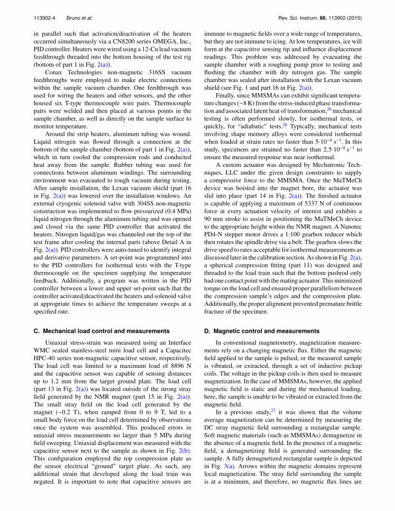
Fig. 7(a) shows the measured shape memory e↵ect ofa Ni45Co5Mn36.6In13.4 (at. %) single crystal under 25 MPacompressive stress and 1 T applied field along the [001]austenite direction. The Af temperature of this sample wastuned by annealing28,29 to be 18 �C under zero stress andfield condition. The sample is heated and cooled at 2 �C/minand was initially heated to 30 �C. At 30 �C, the sampleexhibited a compressive strain equal to that generated bythe elastic response of the austenite phase under 25 MPaand a magnetization level of approximately 91 emu/g. Thismagnetization level is comparable to SQUID measurementsof austenite in samples with similar heat treatment andcomposition.3,7,30 Upon cooling, the MMSMA transforms toits martensitic phase below 10 �C and exhibits approximately5.7% transformation strain under the 25 MPa. The changein magnetization of 92 emu/g compares well with SQUIDmeasurements performed under zero mechanical load. Thesmall increase in magnetization from 30 �C to 10 �C, oncooling, can be attributed to cooling below the Curie pointof austenite and promoting the magnetic order. As expected,the magnetic response of martensite is small, below 20 emu/g.Finally, it can be seen that the thermal hysteresis across thetransformation is approximately 11 �C.
Across the temperature induced phase transformation,in Fig. 7(a), the load was held constant. The constantload is plotted as a function of temperature in Fig. 7(b).During heating and cooling, the MMSMA exhibited thermalexpansion, and therefore, the spindle drive actuator constantlymade adjustments to the applied mechanical load to accountfor load changes through the thermal expansion of theMMSMA. Through trial and error, the spindle drive controlparameters were optimized for a specific heating/coolingand field ramping rate. The custom LabVIEW script sentthe optimized control parameters to the spindle drive toadjust the stress under any given temperature and fieldramping rate. As shown in Fig. 7(b), during most of theheating/cooling performed in Fig. 7(a), the stress was heldconstant within ±2.7 MPa of the given set-point. Duringthe martensitic transformation, however, the stress deviatedby as much as 4 MPa (see M–A in Fig. 7(b)) due tothe rapid nucleation and propagation of the reverse (M–A)transformation. Nevertheless, the precision achieved withthe custom linear actuator and LabVIEW script rivals the
This article is copyrighted as indicated in the article. Reuse of AIP content is subject to the terms at: http://scitationnew.aip.org/termsconditions. Downloaded to IP:50.24.40.181 On: Wed, 11 Nov 2015 16:16:23
113902-9 Bruno et al. Rev. Sci. Instrum. 86, 113902 (2015)
FIG. 7. The simultaneously measured uniaxial compressive strain and magnetization during heating and cooling at 2 �C/min through the martensitic transfor-mation in a Ni45Co5Mn36.6In13.4 single crystal (a) and the corresponding constant-stress during the testing. During heating and cooling, the compressive loadwas held constant at 25 MPa with the custom LabVIEW script and the magnetic field was 1 T collinear to the [001] austenite crystal direction.
capabilities of other instrumentation that has been shown tohold a constant load during cryogenic thermomagnetic SQUIDmeasurements.7 Further testing similar to the one shown inFigs. 7(a) and 7(b) can allow the shape memory e↵ect (SME)to be investigated under di↵erent fields and mechanical loadsat di↵erent temperatures with high precision to study theirinfluence on materials properties.
B. Superelasticity under magnetic field
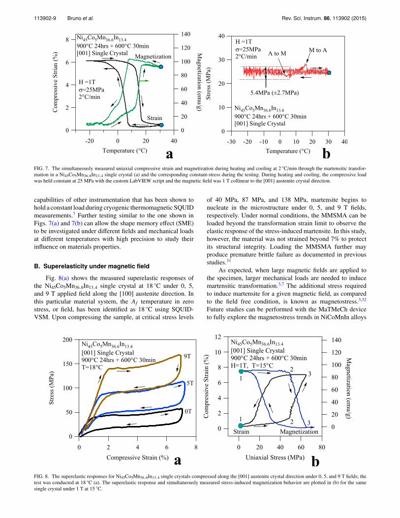
Fig. 8(a) shows the measured superelastic responses ofthe Ni45Co5Mn36.6In13.4 single crystal at 18 �C under 0, 5,and 9 T applied field along the [100] austenite direction. Inthis particular material system, the Af temperature in zerostress, or field, has been identified as 18 �C using SQUID-VSM. Upon compressing the sample, at critical stress levels
of 40 MPa, 87 MPa, and 138 MPa, martensite begins tonucleate in the microstructure under 0, 5, and 9 T fields,respectively. Under normal conditions, the MMSMA can beloaded beyond the transformation strain limit to observe theelastic response of the stress-induced martensite. In this study,however, the material was not strained beyond 7% to protectits structural integrity. Loading the MMSMA further mayproduce premature brittle failure as documented in previousstudies.31
As expected, when large magnetic fields are applied tothe specimen, larger mechanical loads are needed to inducemartensitic transformation.3,7 The additional stress requiredto induce martensite for a given magnetic field, as comparedto the field free condition, is known as magnetostress.3,32
Future studies can be performed with the MaTMeCh deviceto fully explore the magnetostress trends in NiCoMnIn alloys
FIG. 8. The superelastic responses for Ni45Co5Mn36.6In13.4 single crystals compressed along the [001] austenite crystal direction under 0, 5, and 9 T fields; thetest was conducted at 18 �C (a). The superelastic response and simultaneously measured stress-induced magnetization behavior are plotted in (b) for the samesingle crystal under 1 T at 15 �C.
This article is copyrighted as indicated in the article. Reuse of AIP content is subject to the terms at: http://scitationnew.aip.org/termsconditions. Downloaded to IP:50.24.40.181 On: Wed, 11 Nov 2015 16:16:23
113902-10 Bruno et al. Rev. Sci. Instrum. 86, 113902 (2015)
FIG. 9. The fully recoverable magnetic field induced strain (MFIS) in a Ni45Co5Mn36.6In13.4 single crystal uniaxially compressed under 52 MPa along the [001]austenite crystal direction (a) and the corresponding stress-strain data for the same test (b). The test was performed at 18 �C.
and other MMSMAs under various loading conditions andmicrostructures.
Finally, to demonstrate the magnetization measurementcapabilities of the MaTMeCh device during isothermal/isofield compression, Fig. 8(b) shows the magneto-structuralcoupling of the same compression sample at 15 �C under 1 Tapplied field collinear to the load. The physical mechanismsdescribing this type of test are illustrated in Figs. 3(d)-3(f).Again, the sample was only compressed to 7% strain to preventpremature failure. Since 1 T was applied, the transformationtemperatures of the MMSMA experienced a decrease, thus,the sample transforms from A to M at 50 MPa at 15 �Crather than 40 MPa (under 0 T) at 18 �C as illustrated inFig. 8(a). From point 1 to 2 in the figure, the magneticand linear elastic responses of austenite were measured. At acritical stress level (see points 2), the martensite nucleates andthe magnetization level begins to decrease. After achievingnearly complete stress-induced martensite (around 7% totalstrain), the load is removed from point 3 to 1, and themagnetic response and sample geometry are fully recoveredthrough superelasticity. The magnetization is measured to dropapproximately 90 emu/g across the stress-induced martensitictransformation.
C. Magnetic field induced strain (MFIS)
The completely reversible magnetic field induced trans-formation under 52 MPa is shown in Fig. 9(a). Prior tofield ramping, at 18 �C, the MMSMA was compressed toits martensitic state from austenite as shown by Fig. 9(b)(point 1 to 2). These points are also denoted in Fig. 9(a).Once the sample was almost completely comprised of stress-induced martensite (at point 2), the field was ramped fromzero to 6 T (points 2 to 3) at approximately 50 Oe/s(0.3 T/min). This is comparable to the field ramping rates usedin the above mentioned SQUID magnetometer for isothermalmeasurements. Under about 4.1 T, the field-induced M–Atransition began and it finished around 5.3 T. On removing the
field (point 3 to 4), the A–M transition began slightly below2 T and completed around 0 T. The magnetic hysteresis under52 MPa was measured to be nearly 4 T and the reversibleMFIS was measured to be 5.4%. After reaching 0 T, thesample was comprised of stress-induced martensite againand the mechanical load was then removed (point 4 to 5).This recovered the austenite phase. The small deviations instress from points 2 to 3 to 4 in Fig. 9(b) were caused bythe rapid martensitic transformation. Further optimization ofthe linear actuator control parameters is needed to reducethese deviations in the load and future studies can beperformed using the MaTMeCh device on MFITs undervarious mechanical loading conditions.
VII. SUMMARY AND CONCLUSIONS
A MaTMeCh device was designed, assembled, andimplemented for studying the martensitic transformationbehaviors of MMSMAs. The robust device accommodates�100 �C to 120 �C test temperatures, 0–5300 N uniaxialmechanical loads, and 0-9 T collinear-to-load magnetic fields.Uniaxial stress, strain, volume average magnetization, appliedmagnetic field, and temperature are measured simultaneously.The mechanical load, temperature, and magnetic field aredriven independently, therefore, the MaTMeCh device issuitable for studying the e↵ects of mixed loading conditionson single crystalline, or polycrystalline, compression barsamples. In this review, we discussed the shape memory e↵ect,superelasticity, and magnetic field-induced meta-magnetictransitions and these served as a baseline for the MaTMeChdevice design criteria. Finally, the testing capabilities weredemonstrated by a few example data on an exampleMMSMA system, i.e., Ni45Co5Mn36.6In13.4 single crystals.Systematic studies are underway on Ni45Co5Mn36.6In13.4single crystals to reveal the influence of multi-field load-ing on the martensitic transformation characteristics ofMMSMAs.
This article is copyrighted as indicated in the article. Reuse of AIP content is subject to the terms at: http://scitationnew.aip.org/termsconditions. Downloaded to IP:50.24.40.181 On: Wed, 11 Nov 2015 16:16:23
113902-11 Bruno et al. Rev. Sci. Instrum. 86, 113902 (2015)
ACKNOWLEDGMENTS
This work was supported by the U.S. National ScienceFoundation, Division of Materials Research, Metals andMetallic Nanostructures Program, Grant Nos. 1508634 and1108396, the latter of which was under the umbrella ofthe Materials World Network Initiative. In addition, partialsupport from the National Science Foundation, under GrantNo. DMR 08-44082 is acknowledged, which funds researchin the International Materials Institute for Multi-functionalMaterials for Energy Conversion (IIMEC) at Texas A&MUniversity. J.H.R. also acknowledges partial support from theRobert A. Welch Foundation (Grant No. A-1526). N.M.B.would like to also acknowledge Brent McMillan and Mecha-tronic Techniques for developing the custom spindle driveactuator used with the MaTMeCh device, Robert Barber forfruitful design discussions and SolidWorks FEA modeling,and Professor Tom Shield for personal communicationsregarding magnetic measurements.
1R. Kainuma, Y. Imano, W. Ito, H. Morito, Y. Sutou, K. Oikawa, A. Fujita, K.Ishida, S. Okamoto, and O. Kitakami, Appl. Phys. Lett. 88, 192513 (2006).
2N. M. Bruno, C. Yegin, I. Karaman, J. H. Chen, J. H. Ross, J. Liu, and J. G.Li, Acta Mater. 74, 66 (2014).
3H. E. Karaca, I. Karaman, B. Basaran, Y. Ren, Y. I. Chumlyakov, and H. J.Maier, Adv. Funct. Mater. 19, 983 (2009).
4J. I. Perez-Landazabal, V. Recarte, V. Sanchez-Alarcos, S. Kustov, D. Salas,and E. Cesari, Intermetallics 28, 144 (2012).
5X. B. Ren, Phys. Status Solidi B 251, 1982 (2014).6H. E. Karaca, I. Karaman, B. Basaran, Y. J. Chumlyakov, and H. J. Maier,Acta Mater. 54, 233 (2006).
7J. A. Monroe, I. Karaman, B. Basaran, W. Ito, R. Y. Umetsu, R. Kainuma,K. Koyama, and Y. I. Chumlyakov, Acta Mater. 60, 6883 (2012).
8H. E. Karaca, I. Karaman, B. Basaran, D. C. Lagoudas, Y. I. Chumlyakov,and H. J. Maier, Acta Mater. 55, 4253 (2007).
9P. Mullner, V. A. Chernenko, and G. Kostorz, J. Appl. Phys. 95, 1531 (2004).
10K. Haldar, D. C. Lagoudas, and I. Karaman, J. Mech. Phys. Solids 69, 33(2014).
11K. Haldar and D. C. Lagoudas, Proc. R. Soc. A 470, 2169 (2014).12N. M. Bruno, C. Ciocanel, H. P. Feigenbaum, and A. Waldauer, Smart Mater.
Struct. 21, 094018 (2012).13B. Kiefer and D. C. Lagoudas, Philos. Mag. 85, 4289 (2005).14B. Kiefer, H. E. Karaca, D. C. Lagoudas, and I. Karaman, J. Magn. Magn.
Mater. 312, 164 (2007).15R. Kainuma, K. Ito, W. Ito, R. Y. Umetsu, T. Kanomata, and K. Ishida, Mater.
Sci. Forum 635, 23 (2009).16R. Kainuma, Y. Imano, W. Ito, Y. Sutou, H. Morito, S. Okamoto, O. Ki-
takami, K. Oikawa, A. Fujita, T. Kanomata, and K. Ishida, Nature 439, 957(2006).
17Y. Sutou, Y. Imano, N. Koeda, T. Omori, R. Kainuma, K. Ishida, and K.Oikawa, Appl. Phys. Lett. 85, 4358 (2004).
18R. Kainuma, H. Nakano, and K. Ishida, Metall. Mater. Trans. A 27, 4153(1996).
19K. Otsuka and C. M. Wayman, Shape Memory Materials (Cambridge Uni-versity Press, Cambridge, New York, 1998).
20M. Acet and E. F. Wassermann, Adv. Eng. Mater. 14, 523 (2012).21W. Zhu, E. K. Liu, L. Feng, X. D. Tang, J. L. Chen, G. H. Wu, H. Y. Liu, F.
B. Meng, and H. Z. Luo, Appl. Phys. Lett. 95, 222512 (2009).22J. Liu, K. Skokov, and O. Gutfleisch, Scr. Mater. 66, 642 (2012).23A. Sozinov, A. A. Likhachev, N. Lanska, and K. Ullakko, Appl. Phys. Lett.
80, 1746 (2002).24V. K. Pecharsky and K. A. Gschneidner, Phys. Rev. Lett. 78, 4494 (1997).25H. E. Karaca, I. Karaman, A. Brewer, B. Basaran, Y. I. Chumlyakov, and H.
J. Maier, Scr. Mater. 58, 815 (2008).26E. Bonnot, R. Romero, L. Manosa, E. Vives, and A. Planes, Phys. Rev. Lett.
100, 125901 (2008).27T. W. Shield, Rev. Sci. Instrum. 74, 4077 (2003).28N. M. Bruno, Ph.D. dissertation, Texas A&M University, 2015.29J. A. Monroe, J. E. Raymond, X. Xu, M. Nagasako, R. Kainuma, Y. I.
Chumlyakov, R. Arroyave, and I. Karaman, “Multiple ferroic glasses viaordering,” Acta Mater. 101, 107 (2015).
30J. Liu, T. Gottschall, K. P. Skokov, J. D. Moore, and O. Gutfleisch, Nat.Mater. 11, 620 (2012).
31Y. J. Huang, Q. D. Hu, N. M. Bruno, J.-H. Chen, I. Karaman, J. H. Ross, Jr.,and J. G. Li, Scr. Mater. 105, 42 (2015).
32J. A. Monroe, J. Cruz-Perez, C. Yegin, I. Karaman, A. B. Geltmacher, andR. Kainuma, Scr. Mater. 67, 116 (2012).
This article is copyrighted as indicated in the article. Reuse of AIP content is subject to the terms at: http://scitationnew.aip.org/termsconditions. Downloaded to IP:50.24.40.181 On: Wed, 11 Nov 2015 16:16:23


![Magneto-Thermo-Elastic Stresses and Perturbation of ...journals.iau.ir/article_514448_5e4a45850252ceb5d66... · Noda [5] studied the thermal stresses in a FG circular hollow cylinder](https://static.documents.pub/doc/80x56/6001fc195263ae31cf5647fc/magneto-thermo-elastic-stresses-and-perturbation-of-noda-5-studied-the-thermal.jpg)