High-performance Köhler concentrators with uniform irradiance on solar cell M. Hernández a , A. Cvetkovic b , P. Benítez a,b , J. C. Miñano a,b , a Light Prescriptions Innovators Europe. Edificio Cedint, Campus de Montegancedo UPM, 28223, Pozuelo, Madrid, Spain b Universidad Politécnica de Madrid (UPM)-Cedint. Campus de Montegancedo UPM, 28223, Pozuelo, Madrid, Spain ABSTRACT A new free-form XR Köhler concentrator is presented that combines high geometric concentration, high acceptance angle and high irradiance uniformity on the solar cell. This is achieved by modifying the optical surfaces to produce Köhler integration. Although the new optical surfaces (that is, the ones including Köhler integration) behave optically quite different from the ones that do not integrate, but from the macroscopic point of view they are very similar to them. This means that they can be manufactured with the same techniques (typically plastic injection molding or glass molding) and that their production cost is the same i.e., with a high potential for low cost and high optical efficiency. The present approach is completely new and allows keeping the acceptance angle at high values and the concentration factor without increasing the number of optical elements. The simulated optical performance of a Köhler integrating solar concentrator is presented. This concept is the first design combining non flat array of Köhler integrators with concentration optics. Keywords: Nonimaging Optics, high efficiency solar concentrator, Köhler integrator system, high acceptance angle. 1. INTRODUCTION There are two main groups of design problems in Nonimaging Optics. The first group is called “bundle-coupling” and its goal is to maximize the light power transferred from the source to the receiver. The second group of design problems has as objective to obtain a desired pattern at a certain target surface; this type of solutions is called “prescribed irradiance”. In bundle-coupling, the design problem consists in coupling two ray bundles Mi and Mo, called the input and the output bundles respectively. This means that any ray entering into the optical system as a ray of the input bundle Mi exits it as a ray of the output bundle Mo, and vice versa. Thus these two bundles Mi and Mo are formed by the same rays, i.e., they are the same bundle Mc. Mc is in general Mc = Mi I Mo. However, in the prescribed-irradiance type it is only specified that one bundle must be included in the other, Mi in Mo (Mi and Mc will coincide). In this type of solution an additional constraint is to impose that the bundle Mc should produce a prescribed irradiance on a target surfaced. Since the Mc is not fully specified, this design problem is less restrictive than the bundle coupling one. The photovoltaic concentrator (CPV) design is a good example of a design problem which contains both the bundle coupling problem for obtaining maximum acceptance-concentration product as well as the prescribed irradiance in order to obtain uniform irradiance distribution on the solar cell active area. Of course this is a very difficult task and therefore only partial solutions have been found. Good irradiance uniformity on the solar cell can be potentially obtained using two well known methods in the classical optics. These two methods are, firstly light-pipe homogenizer and secondly the Köhler illuminator or integrator [1]. When a light-pipe homogenizer is used, the solar cell is glued to the end of it and the light reaches the cell after some bounces on the light-pipe walls. The light distribution on the cell can be uniform depending on the light-pipe length and shape. The use of light-pipe in the CPV field has some drawbacks. The first one is a need for metallization in the case of high illumination angles what reduces the optical efficiency. The second one is that a longer light-pipe is necessary for better irradiance uniformity what increases the light absorption and decreases the mechanical stability. And the last one is that it is not suitable when small cells are used because the silicon rubber spillage can cause huge losses. Light-pipes have been proposed several times in CPV systems [2][3][4][5][6][7] using a light-pipe length usually much longer than the cell size, typically 4-5 times. The other strategy for achieving good uniformity on the cell (using the Köhler illuminator concept) will be commented in the next sections where some design examples are shown.
Transcript
High-performance Köhler concentrators with uniform irradiance on solar cell
M. Hernándeza, A. Cvetkovicb, P. Beníteza,b, J. C. Miñanoa,b,
a Light Prescriptions Innovators Europe. Edificio Cedint, Campus de Montegancedo UPM, 28223, Pozuelo, Madrid, Spain
b Universidad Politécnica de Madrid (UPM)-Cedint. Campus de Montegancedo UPM, 28223, Pozuelo, Madrid, Spain
ABSTRACT A new free-form XR Köhler concentrator is presented that combines high geometric concentration, high acceptance angle and high irradiance uniformity on the solar cell. This is achieved by modifying the optical surfaces to produce Köhler integration. Although the new optical surfaces (that is, the ones including Köhler integration) behave optically quite different from the ones that do not integrate, but from the macroscopic point of view they are very similar to them. This means that they can be manufactured with the same techniques (typically plastic injection molding or glass molding) and that their production cost is the same i.e., with a high potential for low cost and high optical efficiency. The present approach is completely new and allows keeping the acceptance angle at high values and the concentration factor without increasing the number of optical elements. The simulated optical performance of a Köhler integrating solar concentrator is presented. This concept is the first design combining non flat array of Köhler integrators with concentration optics. Keywords: Nonimaging Optics, high efficiency solar concentrator, Köhler integrator system, high acceptance angle. 1. INTRODUCTION There are two main groups of design problems in Nonimaging Optics. The first group is called “bundle-coupling” and its goal is to maximize the light power transferred from the source to the receiver. The second group of design problems has as objective to obtain a desired pattern at a certain target surface; this type of solutions is called “prescribed irradiance”. In bundle-coupling, the design problem consists in coupling two ray bundles Mi and Mo, called the input and the output bundles respectively. This means that any ray entering into the optical system as a ray of the input bundle Mi exits it as a ray of the output bundle Mo, and vice versa. Thus these two bundles Mi and Mo are formed by the same rays, i.e., they are the same bundle Mc. Mc is in general Mc = Mi I Mo. However, in the prescribed-irradiance type it is only specified that one bundle must be included in the other, Mi in Mo (Mi and Mc will coincide). In this type of solution an additional constraint is to impose that the bundle Mc should produce a prescribed irradiance on a target surfaced. Since the Mc is not fully specified, this design problem is less restrictive than the bundle coupling one. The photovoltaic concentrator (CPV) design is a good example of a design problem which contains both the bundle coupling problem for obtaining maximum acceptance-concentration product as well as the prescribed irradiance in order to obtain uniform irradiance distribution on the solar cell active area. Of course this is a very difficult task and therefore only partial solutions have been found. Good irradiance uniformity on the solar cell can be potentially obtained using two well known methods in the classical optics. These two methods are, firstly light-pipe homogenizer and secondly the Köhler illuminator or integrator [1]. When a light-pipe homogenizer is used, the solar cell is glued to the end of it and the light reaches the cell after some bounces on the light-pipe walls. The light distribution on the cell can be uniform depending on the light-pipe length and shape. The use of light-pipe in the CPV field has some drawbacks. The first one is a need for metallization in the case of high illumination angles what reduces the optical efficiency. The second one is that a longer light-pipe is necessary for better irradiance uniformity what increases the light absorption and decreases the mechanical stability. And the last one is that it is not suitable when small cells are used because the silicon rubber spillage can cause huge losses. Light-pipes have been proposed several times in CPV systems [2][3][4][5][6][7] using a light-pipe length usually much longer than the cell size, typically 4-5 times. The other strategy for achieving good uniformity on the cell (using the Köhler illuminator concept) will be commented in the next sections where some design examples are shown.
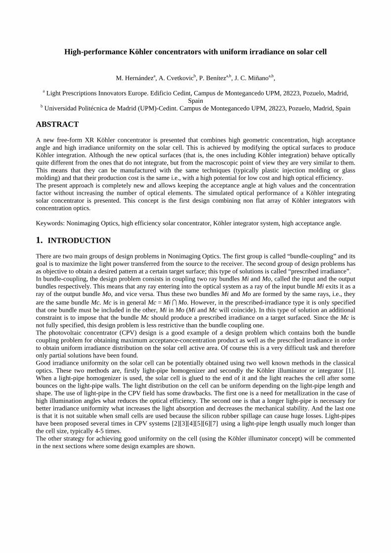
2. THE INTEGRATING CONCENTRATOR APPROACH The first photovoltaic integrating concentrator was proposed [8] by Sandia Labs in the late 80’s, and it was commercialized later by Alpha Solarco. This concentrator used a Fresnel lens as primary and an imaging single surface lens (called SILO, from SIngLe Optical surface) that encapsulates the cell as secondary, see Figure 1. The approach consists on two imaging optical lenses (the Fresnel lens and the SILO) where the Fresnel lens is placed at the SILO’s focal plane, and vice-versa. The effect of using this configuration is that the secondary images on the cell the primary’s aperture which is uniformly illuminated. On the other hand, the primary images the sun on the secondary’s surface. It means that the sun image will move on the secondary surface as the sun moves within the acceptance. Thus the concentrator acceptance is determined by the secondary contour. Another interesting feature of this approach is that if the cell is square the primary can be square trimmed without losing optical efficiency. This is highly attractive for doing a lossless primary tessellation in a module.
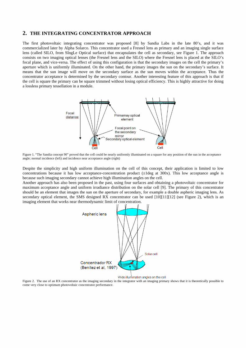
Figure 1. “The Sandia concept 90” proved that the cell could be nearly uniformly illuminated on a square for any position of the sun in the acceptance angle; normal incidence (left) and incidence near acceptance angle (right) Despite the simplicity and high uniform illumination on the cell of this concept, their application is limited to low concentrations because it has low acceptance-concentration product (±1deg at 300x). This low acceptance angle is because such imaging secondary cannot achieve high illumination angles on the cell. Another approach has also been proposed in the past, using four surfaces and obtaining a photovoltaic concentrator for maximum acceptance angle and uniform irradiance distribution on the solar cell [9]. The primary of this concentrator should be an element that images the sun on the aperture of secondary, for example a double aspheric imaging lens. As secondary optical element, the SMS designed RX concentrator can be used [10][11][12] (see Figure 2), which is an imaging element that works near thermodynamic limit of concentration.
Figure 2. The use of an RX concentrator as the imaging secondary in the integrator with an imaging primary shows that it is theoretically possible to come very close to optimum photovoltaic concentrator performance.
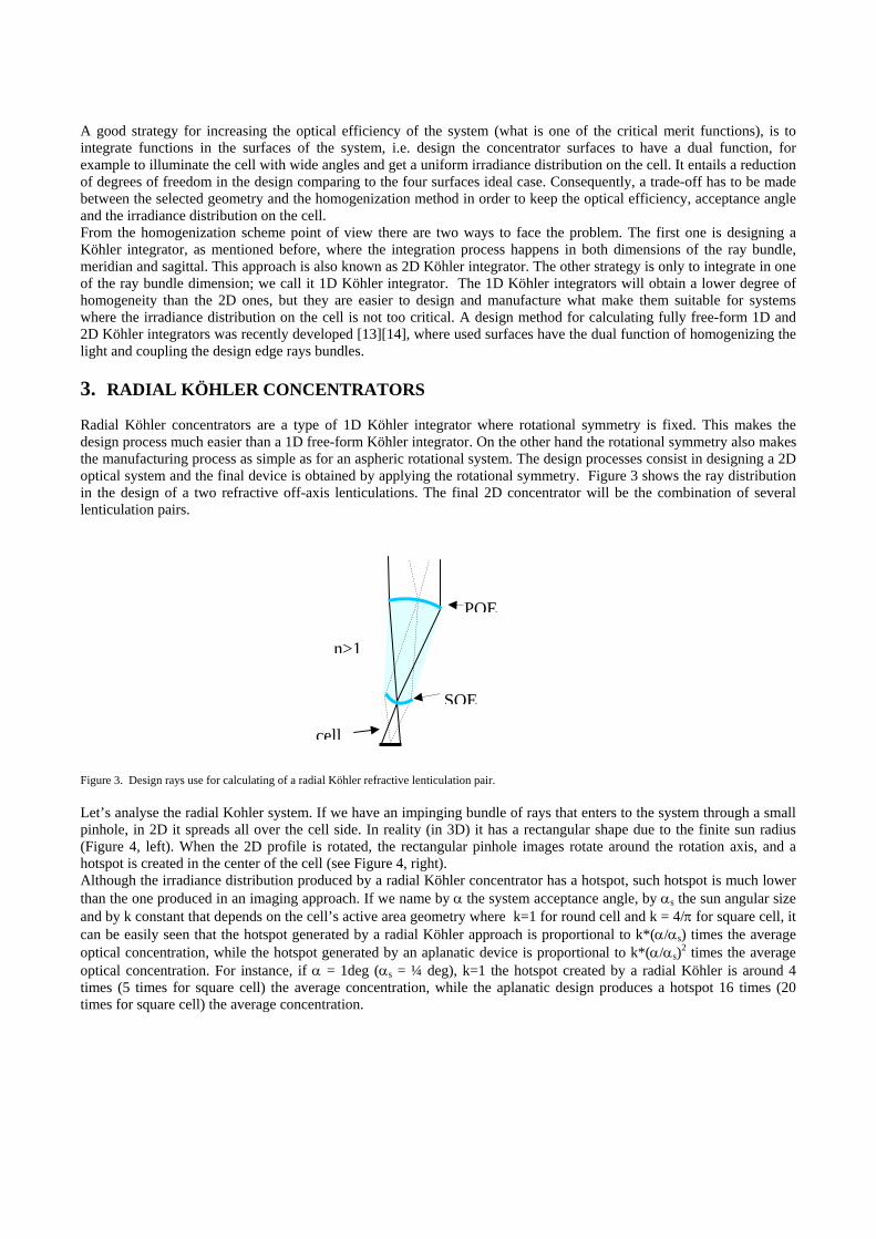
A good strategy for increasing the optical efficiency of the system (what is one of the critical merit functions), is to integrate functions in the surfaces of the system, i.e. design the concentrator surfaces to have a dual function, for example to illuminate the cell with wide angles and get a uniform irradiance distribution on the cell. It entails a reduction of degrees of freedom in the design comparing to the four surfaces ideal case. Consequently, a trade-off has to be made between the selected geometry and the homogenization method in order to keep the optical efficiency, acceptance angle and the irradiance distribution on the cell. From the homogenization scheme point of view there are two ways to face the problem. The first one is designing a Köhler integrator, as mentioned before, where the integration process happens in both dimensions of the ray bundle, meridian and sagittal. This approach is also known as 2D Köhler integrator. The other strategy is only to integrate in one of the ray bundle dimension; we call it 1D Köhler integrator. The 1D Köhler integrators will obtain a lower degree of homogeneity than the 2D ones, but they are easier to design and manufacture what make them suitable for systems where the irradiance distribution on the cell is not too critical. A design method for calculating fully free-form 1D and 2D Köhler integrators was recently developed [13][14], where used surfaces have the dual function of homogenizing the light and coupling the design edge rays bundles. 3. RADIAL KÖHLER CONCENTRATORS Radial Köhler concentrators are a type of 1D Köhler integrator where rotational symmetry is fixed. This makes the design process much easier than a 1D free-form Köhler integrator. On the other hand the rotational symmetry also makes the manufacturing process as simple as for an aspheric rotational system. The design processes consist in designing a 2D optical system and the final device is obtained by applying the rotational symmetry. Figure 3 shows the ray distribution in the design of a two refractive off-axis lenticulations. The final 2D concentrator will be the combination of several lenticulation pairs.
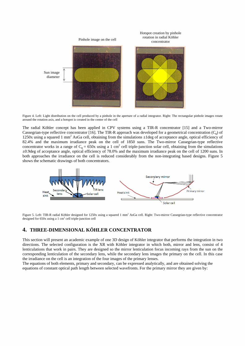
Figure 3. Design rays use for calculating of a radial Köhler refractive lenticulation pair. Let’s analyse the radial Kohler system. If we have an impinging bundle of rays that enters to the system through a small pinhole, in 2D it spreads all over the cell side. In reality (in 3D) it has a rectangular shape due to the finite sun radius (Figure 4, left). When the 2D profile is rotated, the rectangular pinhole images rotate around the rotation axis, and a hotspot is created in the center of the cell (see Figure 4, right). Although the irradiance distribution produced by a radial Köhler concentrator has a hotspot, such hotspot is much lower than the one produced in an imaging approach. If we name by α the system acceptance angle, by αs the sun angular size and by k constant that depends on the cell’s active area geometry where k=1 for round cell and k = 4/π for square cell, it can be easily seen that the hotspot generated by a radial Köhler approach is proportional to k*(α/αs) times the average optical concentration, while the hotspot generated by an aplanatic device is proportional to k*(α/αs)2 times the average optical concentration. For instance, if α = 1deg (αs = ¼ deg), k=1 the hotspot created by a radial Köhler is around 4 times (5 times for square cell) the average concentration, while the aplanatic design produces a hotspot 16 times (20 times for square cell) the average concentration.
cell
SOE
POE
n>1
Figure 4. Left: Light distribution on the cell produced by a pinhole in the aperture of a radial integrator. Right: The rectangular pinhole images rotate around the rotation axis, and a hotspot is created in the center of the cell The radial Köhler concept has been applied in CPV systems using a TIR-R concentrator [15] and a Two-mirror Cassegrian-type reflective concentrator [16]. The TIR-R approach was developed for a geometrical concentration (Cg) of 1250x using a squared 1 mm2 AsGa cell, obtaining from the simulations ±1deg of acceptance angle, optical efficiency of 82.4% and the maximum irradiance peak on the cell of 1850 suns. The Two-mirror Cassegrian-type reflective concentrator works in a range of Cg = 650x using a 1 cm2 cell triple-junction solar cell, obtaining from the simulations ±0.9deg of acceptance angle, optical efficiency of 78.0% and the maximum irradiance peak on the cell of 1200 suns. In both approaches the irradiance on the cell is reduced considerably from the non-integrating based designs. Figure 5 shows the schematic drawings of both concentrators.
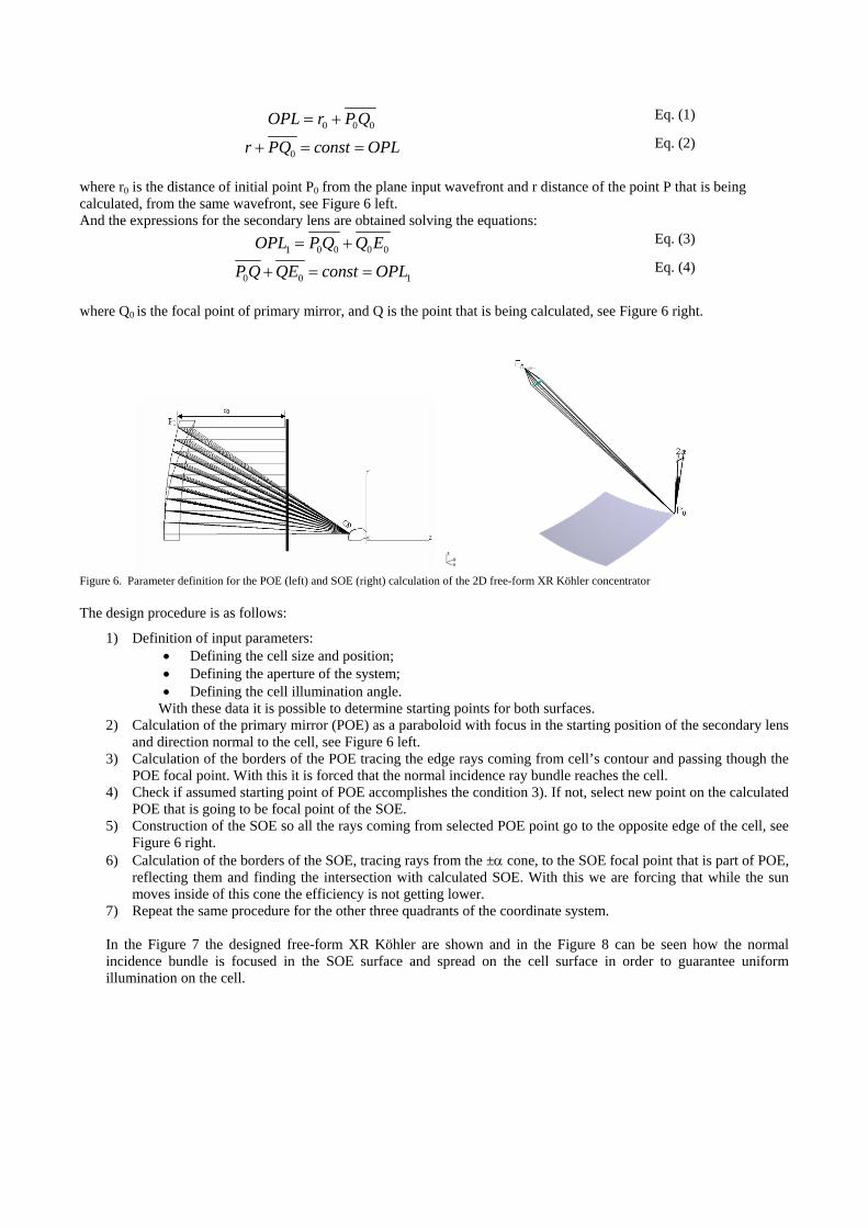
Figure 5. Left: TIR-R radial Köhler designed for 1250x using a squared 1 mm2 AsGa cell. Right: Two-mirror Cassegrian-type reflective concentrator designed for 650x using a 1 cm2 cell triple-junction cell 4. THREE-DIMENSIONAL KÖHLER CONCENTRATOR This section will present an academic example of one 3D design of Köhler integrator that performs the integration in two directions. The selected configuration is the XR with Köhler integrator in which both, mirror and lens, consist of 4 lenticulations that work in pairs. They are designed so the mirror lenticulation focus incoming rays from the sun on the corresponding lenticulation of the secondary lens, while the secondary lens images the primary on the cell. In this case the irradiance on the cell is an integration of the four images of the primary lenses. The equations of both elements, primary and secondary, can be expressed analytically, and are obtained solving the equations of constant optical path length between selected wavefronts. For the primary mirror they are given by:
Pinhole image on the cell
Hotspot creation by pinhole rotation in radial Köhler
concentrator
Sun image diameter
0 0 0OPL r P Q= + Eq. (1)
0r PQ const OPL+ = = Eq. (2)
where r0 is the distance of initial point P0 from the plane input wavefront and r distance of the point P that is being calculated, from the same wavefront, see Figure 6 left. And the expressions for the secondary lens are obtained solving the equations:
1 0 0 0 0OPL P Q Q E= + Eq. (3)
0 0 1P Q QE const OPL+ = = Eq. (4)
where Q0 is the focal point of primary mirror, and Q is the point that is being calculated, see Figure 6 right.
Figure 6. Parameter definition for the POE (left) and SOE (right) calculation of the 2D free-form XR Köhler concentrator The design procedure is as follows:
1) Definition of input parameters: • Defining the cell size and position; • Defining the aperture of the system; • Defining the cell illumination angle.
With these data it is possible to determine starting points for both surfaces. 2) Calculation of the primary mirror (POE) as a paraboloid with focus in the starting position of the secondary lens
and direction normal to the cell, see Figure 6 left. 3) Calculation of the borders of the POE tracing the edge rays coming from cell’s contour and passing though the
POE focal point. With this it is forced that the normal incidence ray bundle reaches the cell. 4) Check if assumed starting point of POE accomplishes the condition 3). If not, select new point on the calculated
POE that is going to be focal point of the SOE. 5) Construction of the SOE so all the rays coming from selected POE point go to the opposite edge of the cell, see
Figure 6 right. 6) Calculation of the borders of the SOE, tracing rays from the ±α cone, to the SOE focal point that is part of POE,
reflecting them and finding the intersection with calculated SOE. With this we are forcing that while the sun moves inside of this cone the efficiency is not getting lower.
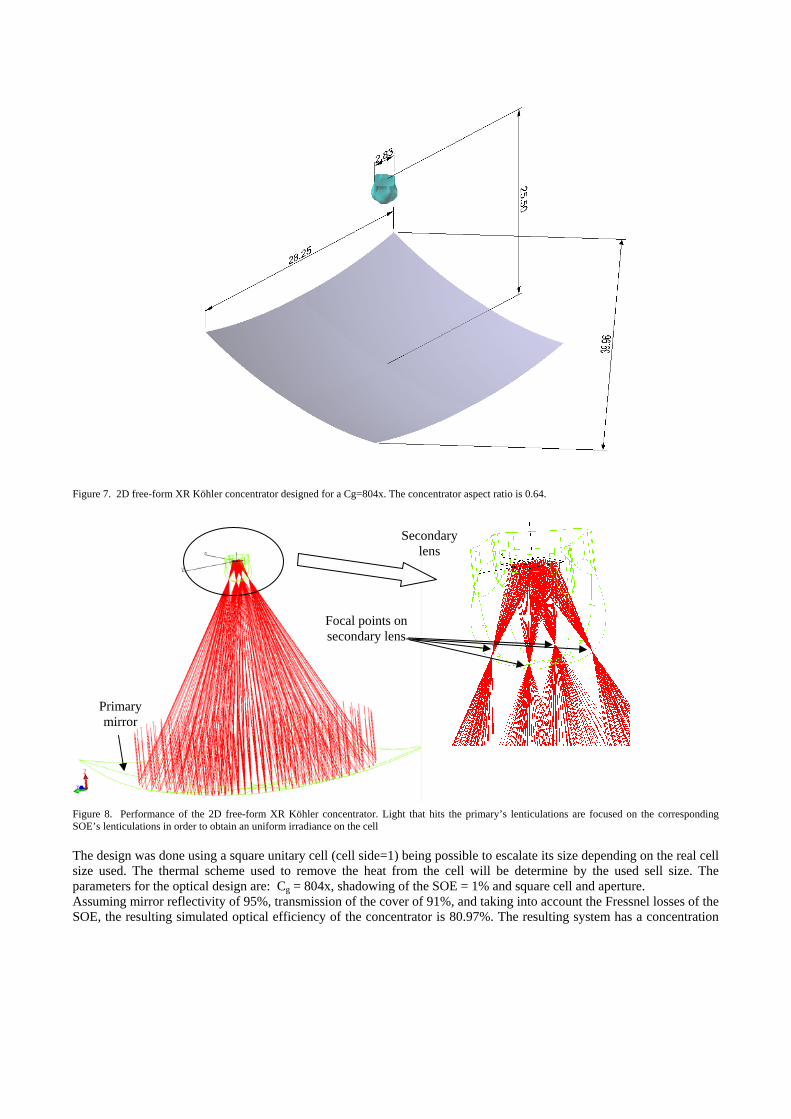
7) Repeat the same procedure for the other three quadrants of the coordinate system. In the Figure 7 the designed free-form XR Köhler are shown and in the Figure 8 can be seen how the normal incidence bundle is focused in the SOE surface and spread on the cell surface in order to guarantee uniform illumination on the cell.
Figure 7. 2D free-form XR Köhler concentrator designed for a Cg=804x. The concentrator aspect ratio is 0.64.
Figure 8. Performance of the 2D free-form XR Köhler concentrator. Light that hits the primary’s lenticulations are focused on the corresponding SOE’s lenticulations in order to obtain an uniform irradiance on the cell The design was done using a square unitary cell (cell side=1) being possible to escalate its size depending on the real cell size used. The thermal scheme used to remove the heat from the cell will be determine by the used sell size. The parameters for the optical design are: Cg = 804x, shadowing of the SOE = 1% and square cell and aperture. Assuming mirror reflectivity of 95%, transmission of the cover of 91%, and taking into account the Fressnel losses of the SOE, the resulting simulated optical efficiency of the concentrator is 80.97%. The resulting system has a concentration
Primary mirror
Secondary lens
Focal points on secondary lens
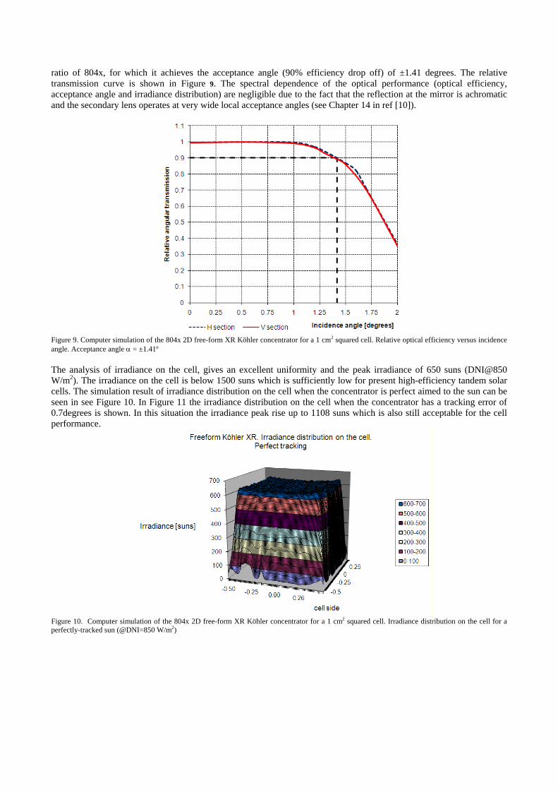
ratio of 804x, for which it achieves the acceptance angle (90% efficiency drop off) of ±1.41 degrees. The relative transmission curve is shown in Figure 9. The spectral dependence of the optical performance (optical efficiency, acceptance angle and irradiance distribution) are negligible due to the fact that the reflection at the mirror is achromatic and the secondary lens operates at very wide local acceptance angles (see Chapter 14 in ref [10]).
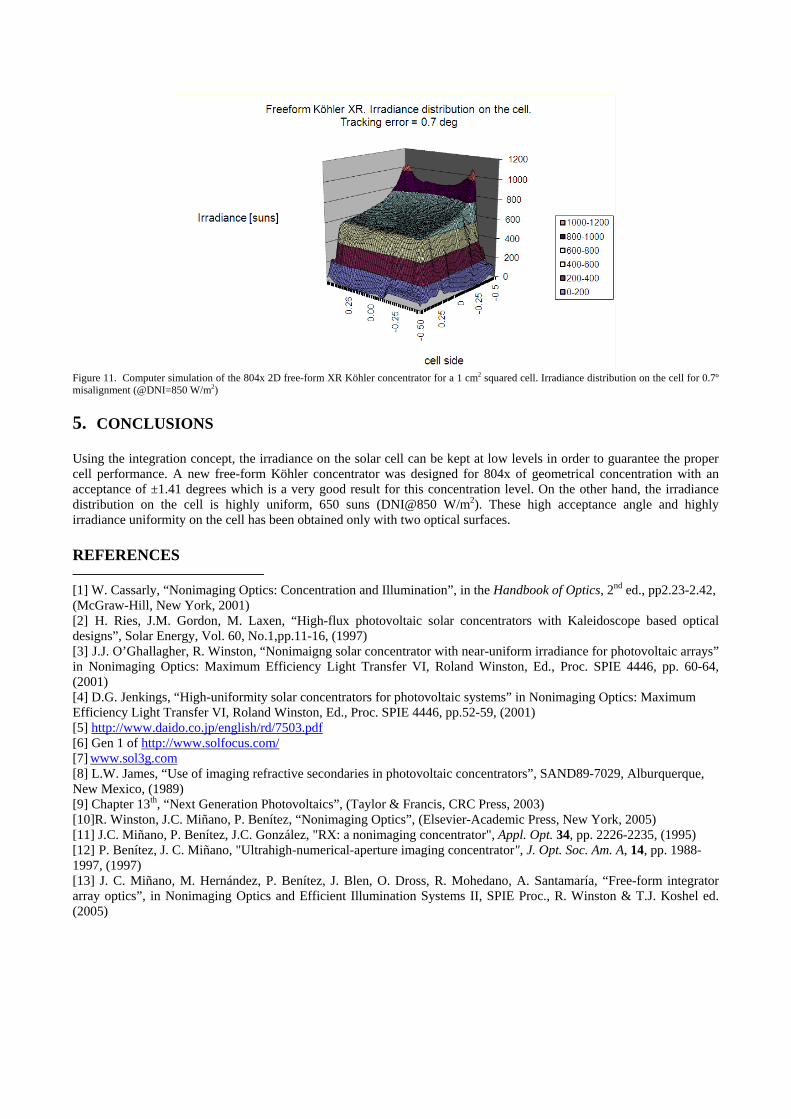
Figure 9. Computer simulation of the 804x 2D free-form XR Köhler concentrator for a 1 cm2 squared cell. Relative optical efficiency versus incidence angle. Acceptance angle α = ±1.41º The analysis of irradiance on the cell, gives an excellent uniformity and the peak irradiance of 650 suns (DNI@850 W/m2). The irradiance on the cell is below 1500 suns which is sufficiently low for present high-efficiency tandem solar cells. The simulation result of irradiance distribution on the cell when the concentrator is perfect aimed to the sun can be seen in see Figure 10. In Figure 11 the irradiance distribution on the cell when the concentrator has a tracking error of 0.7degrees is shown. In this situation the irradiance peak rise up to 1108 suns which is also still acceptable for the cell performance.
Figure 10. Computer simulation of the 804x 2D free-form XR Köhler concentrator for a 1 cm2 squared cell. Irradiance distribution on the cell for a perfectly-tracked sun (@DNI=850 W/m2)
Figure 11. Computer simulation of the 804x 2D free-form XR Köhler concentrator for a 1 cm2 squared cell. Irradiance distribution on the cell for 0.7º misalignment (@DNI=850 W/m2) 5. CONCLUSIONS Using the integration concept, the irradiance on the solar cell can be kept at low levels in order to guarantee the proper cell performance. A new free-form Köhler concentrator was designed for 804x of geometrical concentration with an acceptance of ±1.41 degrees which is a very good result for this concentration level. On the other hand, the irradiance distribution on the cell is highly uniform, 650 suns (DNI@850 W/m2). These high acceptance angle and highly irradiance uniformity on the cell has been obtained only with two optical surfaces. REFERENCES [1] W. Cassarly, “Nonimaging Optics: Concentration and Illumination”, in the Handbook of Optics, 2nd ed., pp2.23-2.42, (McGraw-Hill, New York, 2001) [2] H. Ries, J.M. Gordon, M. Laxen, “High-flux photovoltaic solar concentrators with Kaleidoscope based optical designs”, Solar Energy, Vol. 60, No.1,pp.11-16, (1997) [3] J.J. O’Ghallagher, R. Winston, “Nonimaigng solar concentrator with near-uniform irradiance for photovoltaic arrays” in Nonimaging Optics: Maximum Efficiency Light Transfer VI, Roland Winston, Ed., Proc. SPIE 4446, pp. 60-64, (2001) [4] D.G. Jenkings, “High-uniformity solar concentrators for photovoltaic systems” in Nonimaging Optics: Maximum Efficiency Light Transfer VI, Roland Winston, Ed., Proc. SPIE 4446, pp.52-59, (2001) [5] http://www.daido.co.jp/english/rd/7503.pdf [6] Gen 1 of http://www.solfocus.com/ [7] www.sol3g.com [8] L.W. James, “Use of imaging refractive secondaries in photovoltaic concentrators”, SAND89-7029, Alburquerque, New Mexico, (1989) [9] Chapter 13th, “Next Generation Photovoltaics”, (Taylor & Francis, CRC Press, 2003) [10]R. Winston, J.C. Miñano, P. Benítez, “Nonimaging Optics”, (Elsevier-Academic Press, New York, 2005) [11] J.C. Miñano, P. Benítez, J.C. González, "RX: a nonimaging concentrator", Appl. Opt. 34, pp. 2226-2235, (1995) [12] P. Benítez, J. C. Miñano, "Ultrahigh-numerical-aperture imaging concentrator", J. Opt. Soc. Am. A, 14, pp. 1988-1997, (1997) [13] J. C. Miñano, M. Hernández, P. Benítez, J. Blen, O. Dross, R. Mohedano, A. Santamaría, “Free-form integrator array optics”, in Nonimaging Optics and Efficient Illumination Systems II, SPIE Proc., R. Winston & T.J. Koshel ed. (2005)
[14] Devices shown in this paper are protected by the following US Patents and US and International Patents pending. 6,639,733; 2001069300; CA2402687; 2003282552; 6,896,381; 20040246606; 20050086032; 2005012951;PCT60703667; "Solar Concentrator for Photovoltaics" [15] Hernandez, M. Benitez, P. Minano, J.C. Alvarez, J.L. Diaz, V. Alonso, J., “Sunlight spectrum on cell through very high concentration optics”, 3th World Conference on Photovoltaic Energy Conversion, Osaka, (2003). Volume: 1, On page(s): 889- 891 [16] P. Benitez, A. Cvetkovic, R. Winston, G. Díaz, L. Reed, J. Cisneros, A. Tovar, A. Ritschel, J. Wright, “High-Concentration Mirror-Based Köhler Integrating System for Tandem Solar Cells”, 4th World Conference on Photovoltaic Energy Conversion, Hawaii, (2006)