16
High Performance Output Filter Instruction Manual ZENER R

High Performance Output Filter
Instruction Manual
ZENER
R
IM00109A
ZENER TECHNOLOGY AND QUALITY ASSURANCESince 1976 Zener Electric has supplied many thousands of drives to industry. These drives have been installed into numerous applications resulting in a wealth of in house experience. The Zener High Performance Output Filter is the culmination of this experience, modern technology and industrial application requirements. The Zener Quality Assurance program ensures that every High Performance Output Filter manufactured has been proven to operate correctly in the production test bay before dispatch.
SAFETYYour High Performance Output Filter must be applied, installed and operated in a safe manner. It is the responsibility of the user to ensure compliance with all regulations and practices covering the installation and wiring of your High Performance Output Filter. The instruction manual should be completely read and understood before attempting to connect or operate the High Performance Output Filter. Only skilled personnel should install this equipment.This equipment contains a number of components that are designated by their various manufacturers as “not for use in life support appliances, devices or systems where malfunction of the components can reasonably be expected to result in personal injury or death”. Customers using or selling Zener products for use in such applications do so at their own risk and agree to indemnify Zener for any damage resulting from improper use or sale.
THE CONTENTS OF THIS MANUAL ARE SUBJECT TO CHANGE WITHOUT NOTICE
ZENER is a registered trademark of Zener Electric Pty Limited
iii
ZENER
R
IM00109A
Contents
Contents
Explanation of symbols .............................................................................................................................1Warnings .....................................................................................................................................................1Receiving ....................................................................................................................................................2Performance ...............................................................................................................................................3High Performance Output Filter Mechanical Installation Information ...................................................4High Performance Output Filter Wiring for 3 Phase Supply ..................................................................5
Basic Power Wiring Diagram .............................................................................................................5Small Chassis ....................................................................................................................................6Large Chassis ....................................................................................................................................7Control connections and configuration ...............................................................................................9
Specifications and Ratings...................................................................................................................... 11

iv
ZENER
R
IM00109A
High Performance Output Filter Instruction Manual
Intentionally blank
1
ZENER
R
IM00109A
Warnings
Explanation of symbols
WARNING Indicates a condition or practice that, if the warning is not strictly observed, could result in personal injury or death.
CAUTIONIndicates a condition or practice, if the caution is not strictly observed, could lead to damage or destruction of equipment or a significant impairment of proper operation.
WARNING This symbol is used to highlight an electrical hazard. Failure to strictly observe the warning could result in electrocution.
i This symbol is used to highlight additional information on the product’s capabilities or a common error in installation, commissioning or operation.
Warnings
This manual should be read in conjunction with the MSC-3 Instruction Manual (IM00092).Read all operating instructions before installing, wiring, operating, servicing or inspecting the High Performance Output Filter.Ensure that the instruction manual is made available to the final user of the product as well as all personnel involved in any aspect of installation, adjustment or maintenance.Your High Performance Output Filter must be applied and installed by a suitably qualified and experienced electrical tradesperson in accordance with this manual, good engineering practice and all local rules and regulations
Do not operate the high performance output filter without connections to +B and -B terminals. Damage to equipment may result.
There are hazardous voltages inside the High Performance Output Filter whenever it is connected to an electrical supply and for some time after it is disconnected.Before touching anything inside the High Performance Output Filter enclosure or other equipment connected to the High Performance Output Filter terminals, disconnect all sources of electrical power, wait at least 11 minutes for capacitors within the High Performance Output Filter to discharge to less than 50VDC and then ensure, by measurement, that there is no hazardous AC or DC voltage present at any terminal.
The High Performance Output Filter contains high energy circuits that may be hazardous. Do not operate the High Performance Output Filter with the door open or any part of the enclosure removed. Do not touch the terminals of the High Performance Output Filter or any associated motor and wiring when it is energised, even if the High Performance Output Filter and motor are stopped. Electric shock may result.Do not modify this equipment electrically, mechanically or otherwise. Modification may create safety hazards. The High Performance Output Filter is designed to operate in series with an appropriately rated and otherwise suitable 3 phase induction motor. It is not suitable for single phase motors or other types of motor or non-motor load. Use with inappropriate load types may create a safety hazard.

2
ZENER
R
IM00109A
High Performance Output Filter Instruction Manual
Where the High Performance Output Filter is used as a component part of another product, it is the purchaser’s responsibility to ensure that the final product meets all of the necessary safety, EMC, regulatory, operational and other requirements for that product. Requirements for the purchaser’s final product may be substantially different to the requirements for stand-alone filters.The High Performance Output Filter is intended for use only in fixed wiring applications. It is not intended for use on a flexible supply cable.Mount the High Performance Output Filter on a vertical, incombustible surface such as metal or masonry. Do not place combustible or flammable material near the High Performance Output Filter. Failure to observe these precautions may create a fire hazard.The High Performance Output Filter is manufactured under strict quality control arrangements, however additional and independent safety equipment must be installed if the application is such that failure of the product may result in personal injury or property damage.Ensure that electrical noise generated by the product and any associated equipment does not adversely affect the proper operation of other equipment or systems, particularly those that have a safety function.Do not install this equipment in locations where mechanical damage to the enclosure is possible. In particular, consider vehicles, vandalism and attack by insects or animals. Severe equipment damage and safety hazards may result.
ReceivingInspect the High Performance Output Filter for any shipping damage. If any damage is found, report it to the carrier immediately. Access the inside of the controller and visually check for any damage.Do not attempt to operate the High Performance Output Filter if any obvious damage exists.After the initial inspection, the High Performance Output Filter can be repacked and stored in a clean, dry location until it is required for use. DO NOT store this equipment in an area where the ambient temperature will fall below -20ºC (-4ºF) or rise above 70ºC (158ºF). DO NOT store this equipment in areas that are subject to condensation or corrosive atmosphere. Proper storage is necessary to ensure satisfactory High Performance Output Filter start up and performance.

3
ZENER
R
IM00109A
Installation
PerformanceThe following benefits can be realised with the High Performance Output Filter when connected between the MSC-3 inverter and a motor.
Significant reduction of RF voltages and currents achieving 40dB to 45dB attenuation. Complies with AS61800.3 (Adjustable speed electrical power drive systems, Part 3: EMC
requirements and specific test methods) category C3 limits, category C2 limits and category C1 limits (0.2 to 30MHz) (see below for definitions) in a typical installation with 100m of either unscreened or screened motor cable.
Ideal solution for eliminating AM radio frequency interference Maximum reduction of potential RF voltages and currents achieving 45dB to 50dB attenuation
with screened motor cable. High efficiency, greater than 99.4%; low loss – far less than conventional iron core filters. Regenerative clamping to control peak voltage with long cable runs. Eliminate the need for installing screened motor cables.
The permissible cable length2 between filter and motor is 500m.
Categories as defined in AS61800.3 are:• C1 limits apply to equipment in a domestic environment that do not require installation and
commissioning by a professional.• C2 limits apply to equipment in a domestic environment that do require installation and
commissioning by a professional.• C3 limits apply to equipment in a non-domestic environment.• C4 limits apply to equipment with currents above 400A and special cases.
Maximum rate of change of voltage (dv/dt) = 150V/µsMaximum peak motor voltage with 100m of cable = 120% of bus voltage
Vertical: 200V / div, Horizontal: 5µs / div.Figure 1 – High Performance Output Filter
voltage.
Vertical: 200V / div, Horizontal: 5µs / div.Figure 2 – Motor terminal voltage with 100m of
unscreened cable.
2 Cable resistive voltage drop should be taken into consideration when long cable runs are used.
4
ZENER
R
IM00109A
High Performance Output Filter Instruction Manual
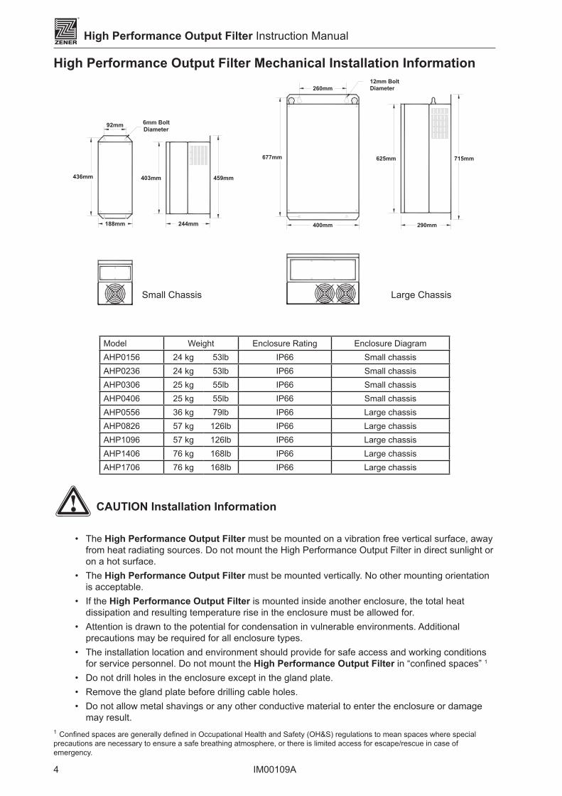
High Performance Output Filter Mechanical Installation Information
188mm
92mm
403mm436mm 459mm
244mm
Diameter
400mm
260mm
625mm677mm 715mm
290mm
12mm BoltDiameter
Model Weight Enclosure Rating Enclosure DiagramAHP0156 24 kg 53lb IP66 Small chassisAHP0236 24 kg 53lb IP66 Small chassisAHP0306 25 kg 55lb IP66 Small chassisAHP0406 25 kg 55lb IP66 Small chassisAHP0556 36 kg 79lb IP66 Large chassisAHP0826 57 kg 126lb IP66 Large chassisAHP1096 57 kg 126lb IP66 Large chassisAHP1406 76 kg 168lb IP66 Large chassisAHP1706 76 kg 168lb IP66 Large chassis
CAUTION Installation Information
• The High Performance Output Filter must be mounted on a vibration free vertical surface, away from heat radiating sources. Do not mount the High Performance Output Filter in direct sunlight or on a hot surface.
• The High Performance Output Filter must be mounted vertically. No other mounting orientation is acceptable.
• If the High Performance Output Filter is mounted inside another enclosure, the total heat dissipation and resulting temperature rise in the enclosure must be allowed for.
• Attention is drawn to the potential for condensation in vulnerable environments. Additional precautions may be required for all enclosure types.
• The installation location and environment should provide for safe access and working conditions for service personnel. Do not mount the High Performance Output Filter in “confined spaces” 1
• Do not drill holes in the enclosure except in the gland plate.• Remove the gland plate before drilling cable holes.• Do not allow metal shavings or any other conductive material to enter the enclosure or damage
may result.1 Confined spaces are generally defined in Occupational Health and Safety (OH&S) regulations to mean spaces where special precautions are necessary to ensure a safe breathing atmosphere, or there is limited access for escape/rescue in case of emergency.
Large ChassisSmall Chassis
5
ZENER
R
IM00109A
Installation
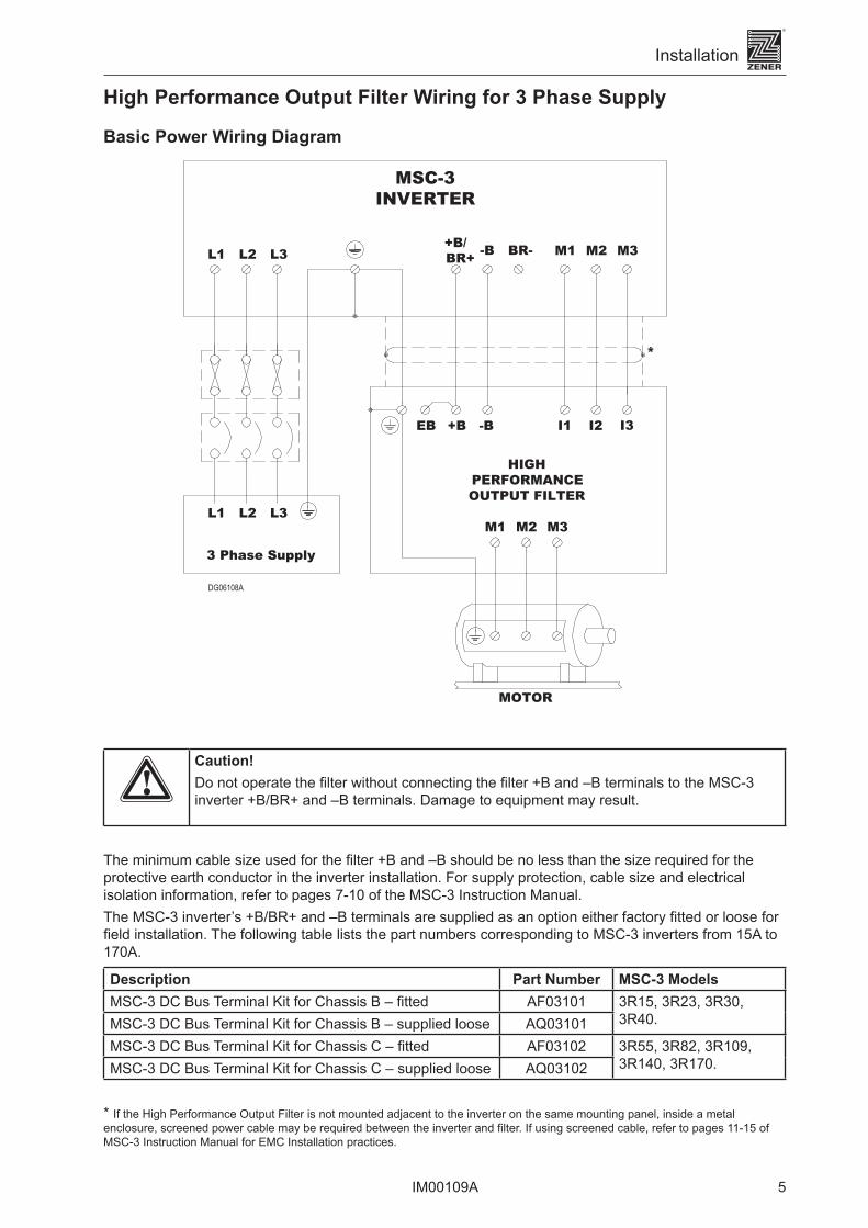
High Performance Output Filter Wiring for 3 Phase Supply
Basic Power Wiring Diagram
L1 L2 L3
L1 L3L2 M1 M3M2
3 Phase Supply
MSC-3INVERTER
DG06108A
MOTOR
M3M2M1
I1 I2 I3
HIGH PERFORMANCE OUTPUT FILTER
EB
*
-B+B
-B+B/BR+ BR-
Caution!Do not operate the filter without connecting the filter +B and –B terminals to the MSC-3 inverter +B/BR+ and –B terminals. Damage to equipment may result.
The minimum cable size used for the filter +B and –B should be no less than the size required for the protective earth conductor in the inverter installation. For supply protection, cable size and electrical isolation information, refer to pages 7-10 of the MSC-3 Instruction Manual.The MSC-3 inverter’s +B/BR+ and –B terminals are supplied as an option either factory fitted or loose for field installation. The following table lists the part numbers corresponding to MSC-3 inverters from 15A to 170A.
Description Part Number MSC-3 ModelsMSC-3 DC Bus Terminal Kit for Chassis B – fitted AF03101 3R15, 3R23, 3R30,
3R40.MSC-3 DC Bus Terminal Kit for Chassis B – supplied loose AQ03101MSC-3 DC Bus Terminal Kit for Chassis C – fitted AF03102 3R55, 3R82, 3R109,
3R140, 3R170.MSC-3 DC Bus Terminal Kit for Chassis C – supplied loose AQ03102
* If the High Performance Output Filter is not mounted adjacent to the inverter on the same mounting panel, inside a metal enclosure, screened power cable may be required between the inverter and filter. If using screened cable, refer to pages 11-15 of MSC-3 Instruction Manual for EMC Installation practices.

6
ZENER
R
IM00109A
High Performance Output Filter Instruction Manual
* If the High Performance Output Filter is not mounted adjacent to the inverter on the same mounting panel, inside a metal enclosure, screened power cable may be required between the inverter and filter. If using screened cable, refer to pages 11-15 of MSC-3 Instruction Manual for EMC Installation practices.
Small Chassis
This cable requires 5 cores and P.E. It may be implemented as two cables for convenience.
ESC
EXITFWD REV ENTER STOP
ZENER ELECTRICMSC-3
T2T1
INPUTL1 L2 L3 +B/
BR+ -B BR- M1 M2 M3MOTOR OUTPUT
M1 M2 M3MOTOR OUTPUT
+B -B EBINPUT
L1 L2 L3
CAUTIONRemove gland plate before drilling holes
*Metal cable gland with 360° screen termination
No special EMC Requirement. Plastic or other cable gland may be used
Motor terminal box
Motor isolation switch (if required)
AC supply screened cable not required
Screened cable not required
Screened cable not recquired
No special EMC requirement. Plastic or other cable gland may be used.
*Screened power cable
No special EMC Requirement. Plastic or other cable gland may be used
Screened control cable

7
ZENER
R
IM00109A
Installation
Large Chassis
ESC
ZENER ELECTRIC
FWD REV ENTER EXIT STOP
MSC-3
AC LINE
L1 L2 L3 M1 M2 M3
MOTOR
BR--B
BRAKING RESISTOROPTIONAL
M1 M2 M3L1 L2 L3
+B/BR+
M1M2 M3I1 I2 I3 +B -B EB
T1 T2
No special EMC Requirement. Plastic or other cable gland may be used
Motor isolation switch (if required)
*Metal cable gland with
360° screen termination
*Screened power cableAC supply screened
cable not required
No special EMC requirement. Plastic or other cable gland may be used.
Screened control cable
Screened cable not recquired
No special EMC Requirement. Plastic or other cable gland may be used
* If the High Performance Output Filter is not mounted adjacent to the inverter on the same mounting panel, inside a metal enclosure, screened power cable may be required between the inverter and filter. If using screened cable, refer to pages 11-15 of MSC-3 Instruction Manual for EMC Installation practices.This cable requires 5 cores and P.E. It may be implemented as two cables for convenience.
CAUTIONRemove gland
plate before drilling holes
Motor terminal box

8
ZENER
R
IM00109A
High Performance Output Filter Instruction Manual
Intentionally blank

9
ZENER
R
IM00109A
Control Connections and Configuration
Control connections and configuration
Wire the T1 and T2 terminals in series with the MSC-3 enable control signal (terminal 6). Excessive filter temperature will disable the MSC-3. When the temperature has fallen sufficiently, the inverter will become enabled.
Control Connections
i When the filter is too hot the MSC-3 will display “NOT EN” on the second line of the display.
WARNINGEnsure that adequate safety measures are in place to prevent injury to personnel due to unexpected motor starting.
Set inverter I2t to no more than filter continuous rating, if the inverter has a higher current rating than the filter. Refer to pages 45 and 46 of the MSC- 3 Instruction Manual.
Refer to MSC-3 Instruction Manual for control wiring
CAUTIONFailure to connect Protective Thermal Switch may void warranty.
�
1 2 3 4 5 6
+5V D1 D2 D3 D4 EN
MSC-3 Control Board
Ө
T1
T2
TO CONTROL WIRING
Protectivethermal switchnormally closed.Located in filter.
10 IM00109A
ZENER
R
High Performance Output Filter Instruction Manual
Intentionally blank

11IM00109A
ZENER
R
Specifications and Ratings
Specifications and Ratings
General SpecificationVoltage Rating 380 to 480Vac, -15% +10%
3 phase 0-200Hz
Phase to Phase voltage drop at output terminals
4.7Vac
Maximum rate of change of voltage dv/dt 150V/µsPeak motor terminal voltage with 100m of motor cable
120% of peak mains voltage
Enclosure IP66Storage temperature -20°C to +70°C
-4°F to +158°FOperating temperature 0°C to +40°C
32°F to +104°F(Consult Zener for higher ratings)
Relative Humidity 5 to 95% non-condensingAltitude 0 to 1000m
0 to 3281ft
Standards complianceWhen used with Zener MSC-3 inverter
Complies with the Australian EMC framework requirements
Adjustable speed electrical power drive systems Part 3: EMC requirements and specific test methods
IEC 61800.3AS 61800.3
ModelCurrent Rating
Heat Dissipation Efficiency Chassis
SizeContinuous @ 40°C
Intermittent 60s
Intermittent 10s
AHP0156 15A 22.5A 30A 48W 99.55% SmallAHP0236 23A 34.5A 46A 88W 99.47% SmallAHP0306 30A 45.0A 60A 87W 99.60% SmallAHP0406 41A 61.5A 82A 146W 99.49% SmallAHP0556 57A 85.5A 114A 217W 99.45% LargeAHP0826 82A 123A 164A 291W 99.51% LargeAHP1096 114A 171A 228A 434W 99.45% LargeAHP1406 140A 210A 280A 437W 99.57% LargeAHP1706 170A 255A 340A 651W 99.47% Large
AustralianManufacturers
ZENER ELECTRIC PTY LIMITEDACN 001 595 428
ZENER
R
DELIVERY ADDRESS POSTAL ADDRESS
366 Horsley RoadMILPERRANSW 2144AUSTRALIA
P.O. Box 4462MILPERRA DCNSW 1891AUSTRALIA
Tel: Fax:Email:
+61-2-9795 3600+61-2-9795 [email protected]
http:// www.zener.net© Zener Electric Pty Limited 2007
IM00109A23 April 2007


![Hierarchical Histogram-based Median Filter for GPUsuni-obuda.hu/journal/Szanto_Feher_81.pdf · The generalization of the median filter is the rank order filter [3], where the output](https://static.documents.pub/doc/80x56/5e4b6ea61618287113519871/hierarchical-histogram-based-median-filter-for-gpusuni-obudahujournalszantofeher81pdf.jpg)


