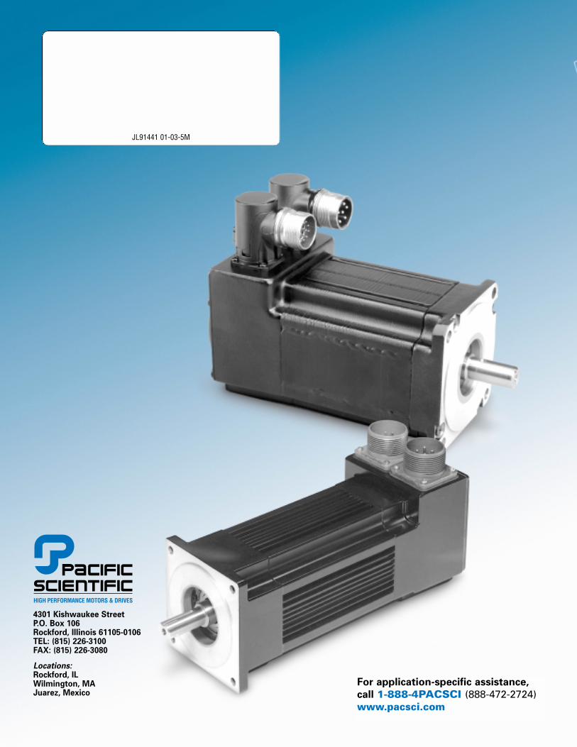
JL91441 01-03-5M 4301 Kishwaukee Street P.O. Box 106 Rockford, Illinois 61105-0106 TEL: (815) 226-3100 FAX: (815) 226-3080 Locations: Rockford, IL Wilmington, MA Juarez, Mexico For application-specific assistance, call 1-888-4PACSCI (888-472-2724) www.pacsci.com
Transcript
March, 2001
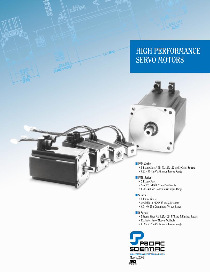
■ PMA Series• 5 Frame Sizes N 55, 70, 115, 142 and 190mm Square• 0.21 - 54 Nm Continuous Torque Range
■ PMB Series• 3 Frame Sizes• Size 17, NEMA 23 and 34 Mounts• 0.22 - 4.8 Nm Continuous Torque Range
■ S Series• 2 Frame Sizes• Available in NEMA 23 and 34 Mounts• 0.5 - 6.6 Nm Continuous Torque Range
■ R Series• 5 Frame Sizes N 2, 3.25, 4.25, 5.75 and 7.5 Inches Square• Explosion Proof Models Available• 0.32 - 50 Nm Continuous Torque Range
HIGH PERFORMANCESERVO MOTORS
PACIFIC SCIENTIFICBRUSHLESS
SERVO MOTORS
A Full Spectrum of PowerfulBrushless ServomotorsPacific Scientific servomotors arebuilt for long, maintenance-freeservice life. Once installed, youprobably won't have to look at them
PMB SeriesThe PMB Series of brushlessservomotors introduces an IP40construction motor in three frames;size 17 and NEMA 23 & 34 to addressyour need for a high-performancemotor in higher-volume applications.With a continuous rated torquerange from 0.22 to 4.8 Nm, the cost-effective PMB motorscomplement our full line of servos.
R SeriesR Series servomotors offer thehighest torque-to-inertia ratios inthe industry. Engineered for thehighest dynamic response available,these motors come in five framesizes – both NEMA and metricmountings. The R Series covers acontinuous rated torque range from0.32 to 50 Nm.
Pacific Scientific DigitalBrushless Servo Drives –Harness the PowerWhen these motors are combinedwith Pacific Scientific's broadoffering of digital brushless servodrives, they offer a cost-effective,high-performance solution that's tough to beat. The systemspackage motors shown on pages 5 to 9 are only the tip of the iceberg.All of the brushless servomotors are customizable — often withminimal impact on delivery times. From feedback options toapplication-specific windings, we can help with your servo needs.
Pacific Scientific's SC/SCE900 seriesbrushless servo drives continue to be the flagship of our servo drives.No other brushless servo drive offershigher performance. No other driveoffers broader functionality.
The PC800 family of brushless servodrives offers a cost-effective, smalldrive with the best lead time in theindustry.
again. The motors in the followingpages feature Neodymium-iron-boron or Samarium cobalt magnetsfor the highest torque-to-inertiaratios possible. Anti-cog statordesigns deliver smooth low-speedperformance.
PMA SeriesThe PMA Series of brushlessservomotors delivers acomprehensive line of rugged, cost-effective servomotors. Coveringframe sizes from 55mm square to190mm square and a continuousrated torque range of 0.21 to 54 Nm,these motors offer an economicmeans to satisfy the requirements ofyour application. Standard IP65sealing and the availability of IP67washdown duty as an option onselected models allows the PMASeries to stand up to the rigors ofthe factory floor. Global certificationsand input voltages on most modelsto 650 volts assure your machine'sacceptance worldwide.
S SeriesThe S Series brushless servomotorsoffer continuous torques from 0.5 to6.6 Nm. Available in two frame sizeswith both metric and NEMA 23 & 34mounting faces, these compactmotors squeeze a lot of torque into asmall package.
BRUSHLESS SERVO MOTORS
FEATURES & BENEFITS
The PC3400 Series of brushless servo drives brings to you a family ofcost-effective, easy-to-use, intelligentservos from the leaders in service and performance.
Smart technology. Motionsimplified.These systems are a prime example of Pacific Scientific's commitment to offer you smart technology -— the highest-performance productsavailable, customized to suit your applications, and backed byunmatched customer support andquality. We want to help make yourjob easier. For more information,contact our Customer ResponseCenter at (815) 226-3100, or visit our website at www.pacsci.com.
BENEFITSFEATURESPMA/S/R Series Motors
Rugged Brushless Construction
High torque over wide speed range
Anti-cog motor design
IP65 TENV construction standard
Two year warranty
Class H insulation
Overtemperature thermistor
Global approvals and agency recognition
Multiple feedback options
Brake option
PMA/S Series Motors
IP67 protection on selected PMA models
Neodymium-iron-boron magnets
High quality Interconnectron connectors
High voltage models available
S/R Series Motors
NEMA mounting available
Steel bearing inserts
R Series Motors
High torque-to-inertia ratios
PMB Series Motors
MS or AMP mini Mate-N-Lock®
connector options
IP40 Construction
Eliminates brush replacement maintenanceStands up to the rigors of the factory floor
Improved machine throughput
Smooth low-speed operation
Withstands rigorous environments
Quality and reliability for reduced machinedowntime
Longer life for reduced machine downtime
Protection against motor damage
Eases recognition process for a machine
Allows numerous control methods
Improved machine safety
Withstands washdown
Maximum performance, maximum value
Faster installation and maintenance
Improved application flexibility
Improved application flexibility
Longer life for reduced machine downtime
Fast acceleration, improved dynamicresponse
Improved application flexibility
Improved cost-effectiveness for highervolume applications
www.pacsci.com 1
SERVO MOTORS
2
SELECTION OVERVIEW
www.pacsci.com
Torque Range Speed Range Page
PMA1 0.21 - 0.60 7,000 - 9,000 11
PMA2 0.50 - 2.2 3,000 - 6,450 12
PMA4 3.4 - 9.9 600 - 4,700 13
PMA5 8.8 - 20.5 900 - 3,450 14
PMA6 24.5 - 48.5 950 - 1,750 15
PMB1 0.14 11,000 17
PMB2 0.45 - 1.40 4,400 - 10,000 18
PMB3 1.62 - 4.84 1,300 - 6,000 19
S20 0.32 - 1.5 3,400 - 12,500 21
S30 1.9 - 6.4 1,300 - 3,900 22
R20 0.17 - 1.0 3,000 - 11,000 24
R30 0.76 - 3.7 1,700 - 7,000 26
R40 3.6 - 7.3 1,500 - 5,300 27
R60 4.4 - 17.6 1,400 - 6,000 28
R80 10.1 - 48.6 1,200 - 4,000 29
R30P 0.62 - 3.0 1,900 - 7,000 30
R60P 3.6 - 14.4 1,500 - 6,000 31
240V ac, 320V dc busBrushless
Servomotors
PMA
PMB
S Series
R Series
R SeriesExplosion Proof
Typical Maximum Continuous Rated Torque (Nm) and Speed (rpm)
Torque Range Speed Range Page
PMA4 3.0 - 9.5 1,600 - 6,000 13
PMA5 7.2 - 19.0 1,900 - 4,200 14
PMA6 19.0 - 43.8 1,350 - 3,300 15
S30 4.0 - 4.3 3,000 22
400V ac, 560V dc busBrushless
Servomotors
PMA
S Series
Typical Maximum Continuous Rated Torque (Nm) and Speed (rpm)
Torque Range Speed Range Page
PMA4 2.6 - 9.3 2,100 - 6,800 13
PMA5 6.8 - 18.6 2,200 - 4,750 14
PMA6 17.5 - 42.2 1,600 - 3,800 15
S30 3.6 - 3.9 3,600 - 3,900 22
480V ac, 640V dc busBrushless
Servomotors
PMA
S Series
Typical Maximum Continuous Rated Torque (Nm) and Speed (rpm)
Torque Range Speed Range Page
PMB1 0.22 - 0.50 700 - 6,450 17
PMB2 0.61 - 1.10 600 - 1,300 18
48V dc bus Brushless Servomotors
PMB
Typical Maximum Continuous Rated Torque (Nm) and Speed (rpm)
INDEX
3www.pacsci.com
Product Overview Inside front cover
Features 1
Selection Overview 2
How to Use This Selection Guide 3
System Performance DataHow to Construct a System 4
System Performance Data, 48V dc bus 5System Performance Data, 240V ac, 320V dc bus 5System Performance Data, 400V ac, 560V dc bus 8System Performance Data, 480V ac, 640V dc bus 9
PMA Series Brushless Servomotors 10
• Model Number Codes• Ratings and Characteristics• Metric Mount
PMB Series Brushless Servomotors 16
• Model Number Codes• Ratings and Characteristics• NEMA Mount
S Series Brushless Servomotors 20
• Model Number Codes• Ratings and Characteristics• Metric Mount
R20 Series Round Brushless Servomotors 23
• Model Number Codes• Ratings and Characteristics• Metric Mount
R Series Brushless Servomotors 25
• Model Number Codes• Ratings and Characteristics• Metric Mount
Brushless Servomotor Feedback Combinations 32
Brushless Servomotor Brake Options 38
Brushless Servomotor Connection Options 39
Cabling and Accessories 43
How to use this selection guide
Use the selection overview on page 2 to identify motorsavailable to fit your systemvoltage, torque and speedrequirements. Detailed systemcombinations with ratings areshown on pages 5 - 9. The tableof contents to the right will helpyou find more information oneach motor family.
Information on the PacificScientific drives mentioned in the following pages can be found in the Pacific Scientificpublication “High PerformanceServo Drives.” A Copy of thispublication can be obtained bycalling Pacific Scientific, or youcan get one by visiting ourwebsite at www.pacsci.com
• If you are already familiar with these motors and theiravailable options, refer to theModel Number Codes on pages10, 16, 20, 23 and 25 to verifycoded information prior toordering.
• If you are not familiar withthese motors and theiravailable options, refer to the index at the right. Note that each frame size is coveredindividually and the technicaldata (last) applies to all motors.Construct a model numberafter all the technicalparameters, including options,are determined.
Our sizing and selectionprogram, Optimizer™ 3.0 can behelpful in determining the correctmotor for your application. Inputthe parameters for your specificapplication and specify your drivevoltage, current and output typeand Optimizer will find themotors that fit the bill. Ask foryour copy today.
SERVO MOTORS
4
HOW TO BUILD ASERVO DRIVE & MOTOR
SYSTEM
Torque (Nm)
Speed (rpm)NL
NO LOAD
SYSTEM VOLTAGE LINE
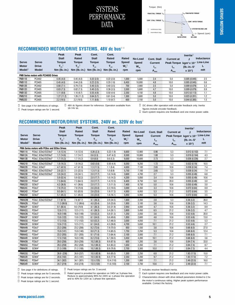
System torque/speed information on the following pages are designed to help you select the optimum brushless servo motor/controller combination.
The nominal values in this data illustrate performance for the recommended motor/controller systems.
DRIVE & MOTOR PERFORMANCE CURVES
The performance characteristics of a brushless servo system (motor/controller combination) are described by a torque/speed operating envelope. Asshown above, the shaded areas of thecurve indicate the continuous duty andintermittent duty zones of the system.
Continuous Duty ZoneThe continuous duty zone is bordered
by the maximum continuous torqueline up to the rated speed of the motor.
The continuous torque line is set by eitherthe motor’s maximum rated temperature, or the controller’s rated continuous currentoutput, whichever is less. The systemvoltage line is set by the voltage rating ofthe controller, the line voltage supplied, andthe motor winding.
The system can operate on a continuous basisanywhere within this area, assuming the motortemperature is 40°C or less, ambient. Refer tothe Test Conditions on the pages that follow.
Intermittent Duty ZoneThe intermittent duty zone is bordered
by the peak torque line and the systemvoltage line.
The peak torque line is set by either thecontroller’s peak current rating, which the
controller can produce for a limited time, orthe maximum rated current for the motor,whichever is less. Refer to the Rating Dataon the pages that follow.
NOTE: higher torque levels may beachievable at higher power levels. ConsultPacific Scientific for more details.
The system voltage line is set by thevoltage rating of the controller, the linevoltage applied and the motor winding.
Operation in the intermittent zone must be limited to a duty cycle that will producean RMS system torque falling within thecontinuous duty area. The RMS torquevalue is defined by the magnitude of theintermittent torque and the percentage ofthe time spent at that torque.
Zero - Peak, or RMS?Current brushless drive technology uses
a sinusoidal output. Pacific Scientific ratesits systems using RMS values to accuratelyreflect system performance operating with asinusoidal waveform.
Older published ratings were based on 0 - peak values, using a trapezoidal waveform.
Optimizer 3.0For more information on any motor on the
following pages, or to take a closer look at
detailed torque/speed information, take a look at our sizing and selectionprogram, Optimizer™ 3.0. With Optimizer’ssine/trapezoidal conversion algorithm, youcan see how our motors pair up with atrapezoidal drive, too. Call Pacific Scientific at 815-226-3100 to get your free copy today,or visit our website at www.pacsci.com.
Additional ReferencesOn the pages that follow, each individual
system has reference points in a table. In addition to rating points for peak (TPS) and continuous torque (TCS) ratings at stall, each system has:• Rated speed (WR)• Continuous torque at rated speed (TCR)• Peak torque at rated speed (TPR)• Motor unloaded speed (WNL)
To construct a curve, follow the guidelinespresented in the generic curve above.System rated speeds and torques arebased on the intersection of the systemvoltage line and the peak current line.Differing peak currents will impact ratedsystem speeds.
The points are provided for reference for use in comparing and sizing systems.
➅ Rated speed is provided for operation on 240V ac 3-phase line. Reduce to approximately 85% for 240V ac 1-phase line operationand to 40% for 120V ac 1-phase line operation.
➆ Includes resolver feedback inertia.
➇ Each system requires one feedback and one motor power cable.
➈ Characteristics shown with drive default parameters limited to 2.5x
the motor’s continuous rating. Higher peak system performanceavailable. Contact the factory.
SERVO MOTORS
6 www.pacsci.com
SYSTEMS PERFORMANCE
DATAcontinuous duty
intermittent duty
Torque (Nm)
Speed (rpm)NL
NO LOAD
SYSTEM VOLTAGE LINE
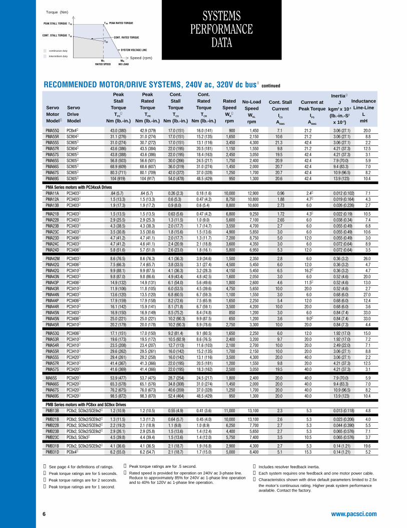
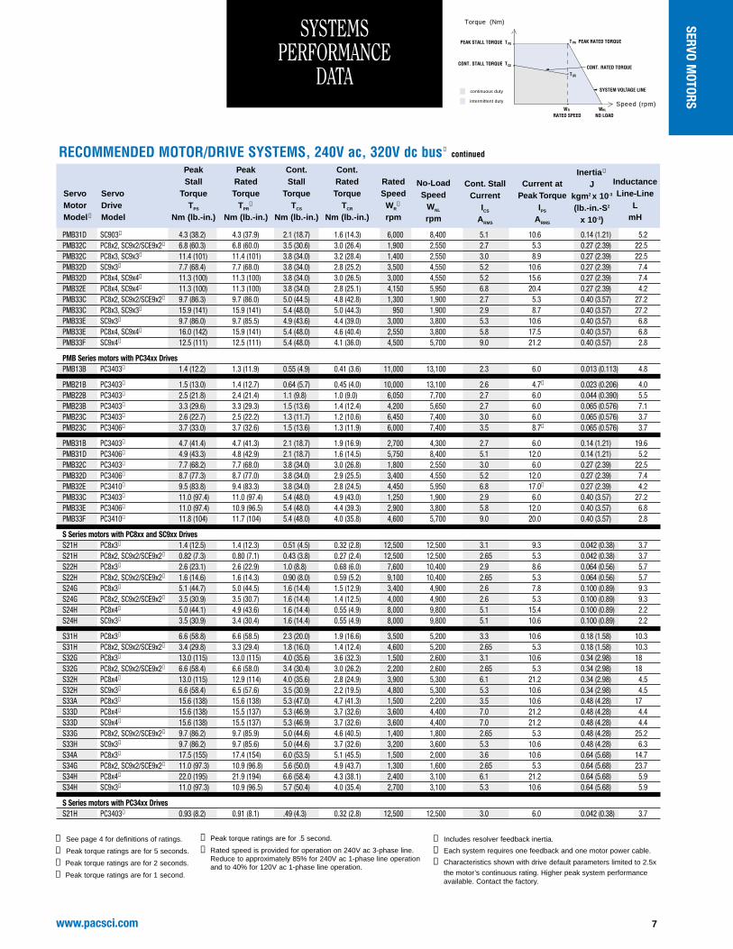
RECOMMENDED MOTOR/DRIVE SYSTEMS, 240V ac, 320V dc bus ➀ continued
Model ➇ Model Nm (lb.-in.) Nm (lb.-in.) Nm (lb.-in.) Nm (lb.-in.) rpm mH
No-LoadSpeed
WNL
rpm
Cont. StallCurrent
ICS
ARMS
Current atPeak Torque
IPS
ARMS
Inertia ➆
Jkgm2 x 10-3
(lb.-in.-S2
x 10-3)
➀ See page 4 for definitions of ratings.
➁ Peak torque ratings are for 5 seconds.
➂ Peak torque ratings are for 2 seconds.
➃ Peak torque ratings are for 1 second.
➄ Peak torque ratings are for .5 second.
➅ Rated speed is provided for operation on 240V ac 3-phase line. Reduce to approximately 85% for 240V ac 1-phase line operationand to 40% for 120V ac 1-phase line operation.
➆ Includes resolver feedback inertia.
➇ Each system requires one feedback and one motor power cable.
➈ Characteristics shown with drive default parameters limited to 2.5x
the motor’s continuous rating. Higher peak system performanceavailable. Contact the factory.
www.pacsci.com 7
SYSTEMS PERFORMANCE
DATA
RECOMMENDED MOTOR/DRIVE SYSTEMS, 240V ac, 320V dc bus ➀ continued
Model ➇ Model Nm (lb.-in.) Nm (lb.-in.) Nm (lb.-in.) Nm (lb.-in.) rpm mH
No-LoadSpeed
WNL
rpm
Cont. StallCurrent
ICS
ARMS
Current atPeak Torque
IPS
ARMS
Inertia ➆
Jkgm2 x 10-3
(lb.-in.-S2
x 10-3)
continuous duty
intermittent duty
Torque (Nm)
Speed (rpm)NL
NO LOAD
SYSTEM VOLTAGE LINE
SERVO MOTORS
➀ See page 4 for definitions of ratings.
➁ Peak torque ratings are for 5 seconds.
➂ Peak torque ratings are for 2 seconds.
➃ Peak torque ratings are for 1 second.
➄ Peak torque ratings are for .5 second.
➅ Rated speed is provided for operation on 240V ac 3-phase line. Reduce to approximately 85% for 240V ac 1-phase line operationand to 40% for 120V ac 1-phase line operation.
➆ Includes resolver feedback inertia.
➇ Each system requires one feedback and one motor power cable.
➈ Characteristics shown with drive default parameters limited to 2.5x
the motor’s continuous rating. Higher peak system performanceavailable. Contact the factory.
Model ➇ Model Nm (lb.-in.) Nm (lb.-in.) Nm (lb.-in.) Nm (lb.-in.) rpm mH
No-LoadSpeed
WNL
rpm
Cont. StallCurrent
ICS
ARMS
Current atPeak Torque
IPS
ARMS
Inertia ➆
Jkgm2 x 10-3
(lb.-in.-S2
x 10-3)
➀ See page 4 for definitions of ratings.
➁ Peak torque ratings are for 5 seconds.
➂ Peak torque ratings are for 2 seconds.
➃ Peak torque ratings are for 1 second.
➄ Peak torque ratings are for .5 second.
➅ Rated speed is provided for operation on 240V ac 3-phase line. Reduce to approximately 85% for 240V ac 1-phase line operationand to 40% for 120V ac 1-phase line operation.
➆ Includes resolver feedback inertia.
➇ Each system requires one feedback and one motor power cable.
➈ Characteristics shown with drive default parameters limited to 2.5x
the motor’s continuous rating. Higher peak system performanceavailable. Contact the factory.
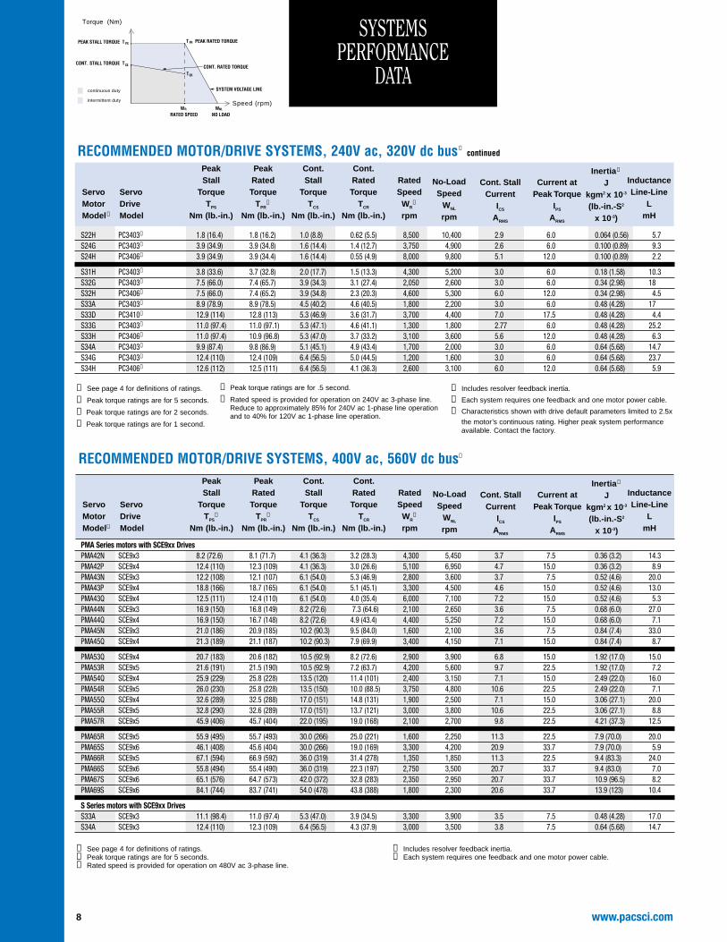
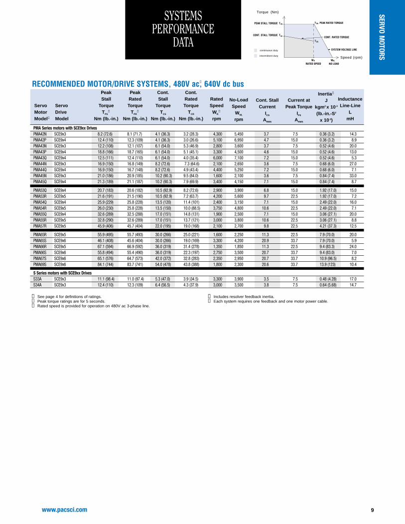
➀ See page 4 for definitions of ratings.➁ Peak torque ratings are for 5 seconds.➂ Rated speed is provided for operation on 480V ac 3-phase line.
➃ Includes resolver feedback inertia.➄ Each system requires one feedback and one motor power cable.
continuous duty
intermittent duty
Torque (Nm)
Speed (rpm)NL
NO LOAD
SYSTEM VOLTAGE LINE
www.pacsci.com 9
SERVO MOTORS
10 www.pacsci.com
➀ Right-Angle type standard; 6-Pin Power = 6PP etc.; 12-Pin Sensor, 0deg. Code.➁ Encoder Mount: Motor prepared to mount external encoder (ROD426).➂ Standard thermal sensor: Thermistor.➃ Mating Connectors available separately. Contact Pacific Scientific.➄ With commutating encoder option, standard feedback connector is 17-pin. See page 32.➅ Oil seal available on PMA1, PMA2 and PMA4 models only (PMA4 requires special endbell with seal option).➆ For more details on encoder mounting provisions, contact Pacific Scientific.➇ Commutating encoder option available on PMA2, PMA4, PMA5 and PMA6 models only.➈ Sin Cos encoder option available on PMA4, PMA5 and PMA6 models only.➉ PMA2 models accept either oil seal option or brake option — not both.
Metric mountingsstandard
Smooth shaft DIN42995N standard.Optional keyway andDIN 42995Rtolerances available
Resolver, commutatingencoder or SinCosencoder primary feedbackdevices available
Neodymium-iron-boronrotor magnets
High-quality Interconnectronpower and feedbackconnectors standard
P M A 4 2 R - 0 0 1 0 0 - 0 0
Pacific Scientific
Frame Size
1 = 55mm motor body square2 = 70mm motor body square4 = 115mm motor body square5 = 142mm motor body square6 = 190mm motor body square
WindingWinding Designator: Nominal Stall 240V ac max. 240-480V ac Current, ARMS
A L 1.3B M 2.7C N 3.8D P 5.4E Q 7.4F R 11.0G S 22.0
Customization Code, Factory assigned
00 = Standard Motor01 = Indicates Oil Seal ➅ ➉
Shaft
0 = Smooth Shaft, DIN42955 N1 = Closed Keyway, Key Fitted, DIN42995 N (Not available PMA1)3 = Smooth Shaft, DIN42955 R4 = Closed Keyway, Key Fitted, DIN42995 R (Not available PMA1)
Brushless Servomotors
Product Series
Stack Length
1-9 = Stack length multiple
Brake➉
0 = No Brake1 = 24V Brake
Connector ➀
1 = 6PP, 12PSO➃
= 6PP, 17PSO➄
Sensor
00 = Resolver12 = Digital Encoder with commutation, 1024 ppr ➇
14 = Digital Encoder with commutation, 2048 ppr ➇
20 = SinCos Encoder (Stegmann SNS50/60)➇ ➈
30 = Resolver with Encoder Mount ➆
Fully-enclosedmotor construction
Optional integral parkingbrake available. The brake isinternal — adds no length tothe standard motor
Rugged TENV, IP65construction. IP67 sealingavailable on selectedmodels
THE MOST RUGGED, COMPREHENSIVE LINE OF COST-EFFECTIVE SERVOMOTORS
➁ ➂
PMA SERIESBRUSHLESS
SERVO MOTORS
www.pacsci.com
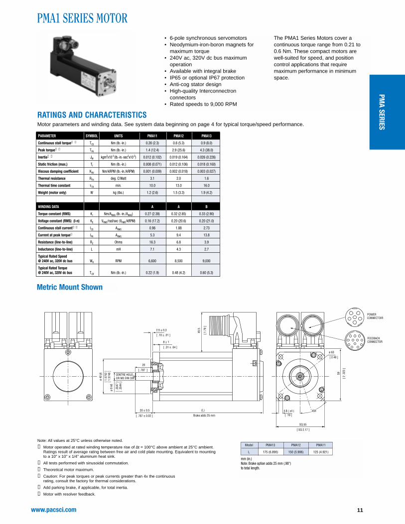
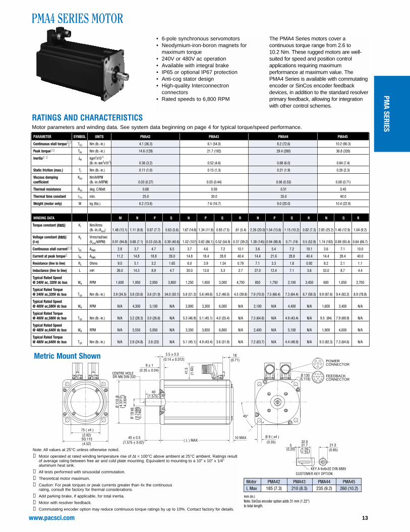
RATINGS AND CHARACTERISTICSMotor parameters and winding data. See system data beginning on page 4 for typical torque/speed performance.
Note: All values at 25°C unless otherwise noted.
➀ Motor operated at rated winding temperature rise of ∆t = 100°C above ambient at 25°C ambient.Ratings result of average rating between free air and cold plate mounting. Equivalent to mountingto a 10" x 10" x 1/4" aluminum heat sink.
➁ All tests performed with sinusoidal commutation.
➂ Theoretical motor maximum.
➃ Caution: For peak torques or peak currents greater than 4x the continuous rating, consult the factory for thermal considerations.
➄ Add parking brake, if applicable, for total inertia.
Typical Rated Speed @ 240V ac, 320V dc bus WR RPM 6,600 8,500 9,000
Typical Rated Torque @ 240V ac, 320V dc bus TCR Nm (lb.-in.) 0.22 (1.9) 0.48 (4.2) 0.60 (5.3)
Metric Mount Shown
[ 1.7
9 ]
[ .35
44 ]
[ .35
47 ][ 1
.574
6 ]
[ 1.5
752
]
[ 2 .3
23 ]
[ .19 ]
[ SQ 2.17 ]
[ 2.48 ]
[ .31 ± .04 ]
[ .10 ± .01 ]
[ .787 ]
[ .787 ± 0.02 ]
45.5
ø 9
k6
ø 40
j6
20 ± 0.5
Brake adds 25 mm
DR M3 DIN 332 CENTRE HOLE
8 ± 1
2.5 ± 0.3
SQ.55
45fl
59
4.8 ( x4 )
ø 63
20
CONNECTOIRPOWER
CONNECTORFEEDBACK
(L)
Model PMA13 PMA12 PMA11
L 175 (6.890) 150 (5.906) 125 (4.921)
mm (in.)Note: Brake option adds 25 mm (.98'') to total length.
• 6-pole synchronous servomotors• Neodymium-iron-boron magnets for
maximum torque• 240V ac, 320V dc bus maximum
operation• Available with integral brake• IP65 or optional IP67 protection• Anti-cog stator design• High-quality Interconnectron
connectors • Rated speeds to 9,000 RPM
The PMA1 Series Motors cover acontinuous torque range from 0.21 to 0.6 Nm. These compact motors are well-suited for speed, and positioncontrol applications that requiremaximum performance in minimumspace.
PMA SERIES
www.pacsci.com12
RATINGS AND CHARACTERISTICSMotor parameters and winding data. See system data beginning on page 4 for typical torque/speed performance.
Note: All values at 25°C unless otherwise noted.
➀ Motor operated at rated winding temperature rise of ∆t = 100°C above ambient at 25°C ambient.Ratings result of average rating between free air and cold plate mounting. Equivalent to mountingto a 10" x 10" x 1/4" aluminum heat sink.
➁ All tests performed with sinusoidal commutation.
➂ Theoretical motor maximum.
➃ Caution: For peak torques or peak currents greater than 4x the continuous rating, consult the factory for thermal considerations.
➄ Add parking brake, if applicable, for total inertia.
➅ Motor with resolver feedback.
➆ Commutating encoder option may reduce continuous torque ratings by up to 10%. Contact factoryfor details.
PMA2 SERIES MOTOR
23(0.90)
45 (x4)(1.77)SQ. 70(2.76)
Ø 5.8 ( x4 )(0.23)
Ø 85(3.346)
DR M
4 DI
N 33
2 C
ENTR
E HO
LE
45°
8 ± 1(0.31 ± 0.04)
2.5 ± 0.3(0.10 ± 0.01)
Ø 11
k6
0.43
350.
4332
Ø 60
j62.
3626
2.36
20
( L ) MAX.23 ± 0.5 (0.905 ± 0.02)
43 (1.7
1)
6(0.24)
CONNECTORPOWER
CONNECTORFEEDBACK
)(
)(
12.5(0.49)
3.5(0.14)
15.816.0
0.620.63
CUSTOMER KEY OPTION
KEY A 4x4x16 DIN 6885
)(
Metric Mount Shown
Motor PMA21 PMA22 PMA23 PMA24L Max 143 (5.6) 168 (6.6) 193 (7.6) 218 (8.6)
mm (in.)Note: Commutating encoder option adds 15 mm (0.59”) to total length.
• 6-pole synchronous servomotors• Neodymium-iron-boron magnets for
maximum torque• 240V ac, 320V dc bus maximum
operation• Available with integral brake• IP65 or optional IP67 protection• Anti-cog stator design• High-quality Interconnectron
connectors • Rated speeds to 7,400 RPM
The PMA2 Series motors cover acontinuous torque range from 0.5 to 2.6 Nm. These compact motors are well-suited for speed and position control applications requiring maximumperformance in minimum space.The PMA2 Series is available with acommutating encoder, in addition to the standard resolver primary feedback,allowing for integration with other control schemes.
RATINGS AND CHARACTERISTICSMotor parameters and winding data. See system data beginning on page 4 for typical torque/speed performance.
40(1.575)
45°
Ø 130(5.118)
10 MAX.( L ) MAX.
Ø 9 ( x4 )(0.35)
9 ± 1(0.35 ± 0.04)
3.5 ± 0.3(0.14 ± 0.012)
DR M6 DIN 332 CENTRE HOLE
Ø 19
k6Ø
110
j64.
3312
4.33
04
0.74
860.
7482
75 ( x4 )(2.92)SQ.115(4.52)
41.5
(1.6
3)
18(0.71)
CONNECTORPOWER
CONNECTORFEEDBACK
)( )
(
)(
40 ± 0.5(1.575 ± 0.02)
CUSTOMER KEY OPTION
21.5(0.85)
KEY A 6x6x32 DIN 6885
31.732.0
1.251.26
5(0.20)
• 6-pole synchronous servomotors• Neodymium-iron-boron magnets for
maximum torque• 240V or 480V ac operation• Available with integral brake• IP65 or optional IP67 protection• Anti-cog stator design• High-quality Interconnectron
connectors • Rated speeds to 6,800 RPM
The PMA4 Series motors cover acontinuous torque range from 2.6 to 10.2 Nm. These rugged motors are well-suited for speed and position controlapplications requiring maximumperformance at maximum value. The PMA4 Series is available with commutatingencoder or SinCos encoder feedbackdevices, in addition to the standard resolverprimary feedback, allowing for integrationwith other control schemes.
Note: All values at 25°C unless otherwise noted.
➀ Motor operated at rated winding temperature rise of ∆t = 100°C above ambient at 25°C ambient. Ratings resultof average rating between free air and cold plate mounting. Equivalent to mounting to a 10" x 10" x 1/4"aluminum heat sink.
➁ All tests performed with sinusoidal commutation.
➂ Theoretical motor maximum.
➃ Caution: For peak torques or peak currents greater than 4x the continuous rating, consult the factory for thermal considerations.
➄ Add parking brake, if applicable, for total inertia.
➅ Motor with resolver feedback.
➆ Commutating encoder option may reduce continuous torque ratings by up to 10%. Contact factory for details.
Motor PMA42 PMA43 PMA44 PMA45L Max 185 (7.3) 210 (8.3) 235 (9.2) 260 (10.2)
mm (in.)Note: SinCos encoder option adds 31 mm (1.22”)to total length.
➆
PMA SERIES
www.pacsci.com14
RATINGS AND CHARACTERISTICSMotor parameters and winding data. See system data beginning on page 4 for typical torque/speed performance.
PMA5 SERIES MOTOR
DR M8 DIN 332 CENTRE HOLE
3.5 ± 0.1(.14 ± 0.004)
Ø 13
0 j6
5.11
865.
1177
0.94
540.
9450
12 ± 1(.47 ± 0.04)
Ø 165(6.496)
50 ± 0.5(1.968 ± .02)
10 MAX.( L ) MAX.
Ø 24
k6
Ø 11 ( x4 )(0.43)
45°
SQ.142(5.59)
94 ( x4 )(3.70)
50(1.968)
41.5
(1.6
3)
18(0.71)
CONNECTORPOWER
CONNECTORFEEDBACK
KEY A 8x7x40 DIN 6885
CUSTOMER KEY OPTION
5 39.7040.00
1.561.57
27(1.06)(0.20)
)( )
(
)(
2720 PMA5
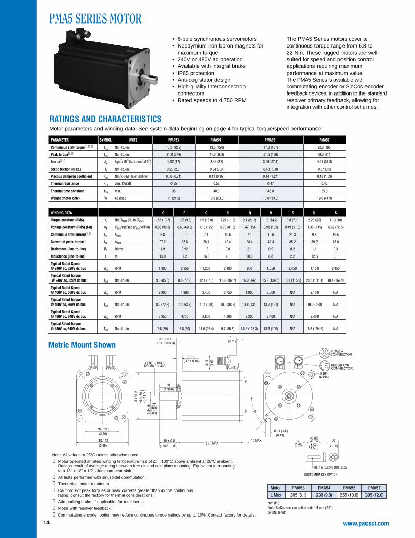
Note: All values at 25°C unless otherwise noted.
➀ Motor operated at rated winding temperature rise of ∆t = 100°C above ambient at 25°C ambient. Ratings result of average rating between free air and cold plate mounting. Equivalent to mounting to a 18" x 18" x 1/2" aluminum heat sink.
➁ All tests performed with sinusoidal commutation.
➂ Theoretical motor maximum.
➃ Caution: For peak torques or peak currents greater than 4x the continuous rating, consult the factory for thermal considerations.
➄ Add parking brake, if applicable, for total inertia.
➅ Motor with resolver feedback.
➆ Commutating encoder option may reduce continuous torque ratings by up to 10%. Contact factory for details.
Motor PMA53 PMA54 PMA55 PMA57L Max 205 (8.1) 230 (9.0) 255 (10.0) 305 (12.0)
mm (in.)Note: SinCos encoder option adds 14 mm (.55”) to total length.
• 6-pole synchronous servomotors• Neodymium-iron-boron magnets for
maximum torque• 240V or 480V ac operation• Available with integral brake• IP65 protection• Anti-cog stator design• High-quality Interconnectron
connectors • Rated speeds to 4,750 RPM
The PMA5 Series motors cover acontinuous torque range from 6.8 to 22 Nm. These rugged motors are well-suited for speed and position controlapplications requiring maximumperformance at maximum value. The PMA5 Series is available withcommutating encoder or SinCos encoderfeedback devices, in addition to the standardresolver primary feedback, allowing forintegration with other control schemes.
15www.pacsci.com
PMA6 SERIES MOTOR
50 41.5
(1.6
3)
(1.9
7)
4 ± 0.3(0.16 ± 0.01)
15 ± 1(0.59 ± 0.04)
Ø 14 ( x4 )(0.55)
Ø 215Ø 8.465
Ø 18
0 j6
Ø 32
k6
DR M12 DIN 332 CENTRE HOLE
( L ) MAX.SQ.190
125 (x4)
(7.48)
(4.92)58 ± 0.5
(2.283 ± 0.02)6 MAX..24 MAX.
45°
58(2.283)
17(0.67)
30(1.18)
CONNECTORPOWER
CONNECTORFEEDBACK
7.08
71
1.26
051.
2600
)(
)( 7.
0862
RATINGS AND CHARACTERISTICSMotor parameters and winding data. See system data beginning on page 4 for typical torque/speed performance.
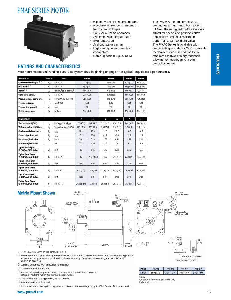
for maximum torque• 240V or 480V ac operation• Available with integral brake• IP65 protection• Anti-cog stator design• High-quality Interconnectron
connectors • Rated speeds to 3,800 RPM
The PMA6 Series motors cover acontinuous torque range from 17.5 to 54 Nm. These rugged motors are well-suited for speed and position controlapplications requiring maximumperformance at maximum value.The PMA6 Series is available withcommutating encoder or SinCos encoderfeedback devices, in addition to thestandard resolver primary feedback,allowing for integration with other control schemes.
Motor PMA65 PMA66 PMA67 PMA69L Max 295 (11.6) 320 (12.6) 345 (13.6) 395 (15.6)
mm (in.)Note: SinCos encoder option adds 14 mm (.55”) to total length.
Note: All values at 25°C unless otherwise noted.
➀ Motor operated at rated winding temperature rise of ∆t = 100°C above ambient at 25°C ambient. Ratings resultof average rating between free air and cold plate mounting. Equivalent to mounting to a 18" x 18" x 1/2"aluminum heat sink.
➁ All tests performed with sinusoidal commutation.
➂ Theoretical motor maximum.
➃ Caution: For peak torques or peak currents greater than 4x the continuous rating, consult the factory for thermal considerations.
➄ Add parking brake, if applicable, for total inertia.
➅ Motor with resolver feedback.
➆ Commutating encoder option may reduce continuous torque ratings by up to 10%. Contact factory for details.
PMA SERIES
www.pacsci.com16
PMB SERIESBRUSHLESS
SERVO MOTORS
➀ Mating connectors not provided.➁ Thermistor not available on PMB1 motors with resolver feedback.
P M B 1 1 B - 0 0 1 0 0 - 0 0
Pacific Scientific
Frame Size
1 = Size 172 = NEMA Size 233 = NEMA Size 34
Winding
Winding Designator: Nominal Stall 240V ac max. Current, ARMS
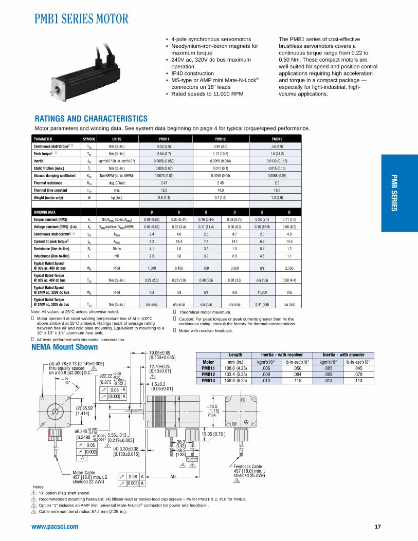
RATINGS AND CHARACTERISTICSMotor parameters and winding data. See system data beginning on page 4 for typical torque/speed performance.
PMB1 SERIES MOTOR
NEMA Mount Shown
• 4-pole synchronous servomotors• Neodymium-iron-boron magnets for
maximum torque• 240V ac, 320V dc bus maximum
operation• IP40 construction• MS-type or AMP mini Mate-N-Lock®
connectors on 18" leads• Rated speeds to 11,000 RPM
The PMB1 series of cost-effectivebrushless servomotors covers acontinuous torque range from 0.22 to0.50 Nm. These compact motors are well-suited for speed and position controlapplications requiring high accelerationand torque in a compact package —especially for light-industrial, high-volume applications.
➀ Motor operated at rated winding temperature rise of ∆t = 100°Cabove ambient at 25°C ambient. Ratings result of average ratingbetween free air and cold plate mounting. Equivalent to mounting to a10" x 10" x 1/4" aluminum heat sink.
➁ All tests performed with sinusoidal commutation.
➂ Theoretical motor maximum.
➃ Caution: For peak torques or peak currents greater than 4x thecontinuous rating, consult the factory for thermal considerations.
➄ Motor with resolver feedback.
Notes:
1 “0” option (flat) shaft shown.
2 Recommended mounting hardware: (4) fillister-lead or socket-lead cap screws – #6 for PMB1 & 2, #10 for PMB3.
3 Option “1” includes an AMP mini universal Mate-N-Lock® connector for power and feedback .
4 Cable minimum bend radius 57.2 mm (2.25 in.).
▲▲▲▲▲▲▲▲▲▲
www.pacsci.com18
(4) 6.10±0.38[0.240±0.015]
AG
8.74±0.13[0.344±0.005]
ø38.10+0.00-0.05
0.08 A
20.57±0.89[0.810±0.035]
1.5±0.3[0.06±0.01]
+0.000-0.010
[0.002]
-A-
ø9.520
0.08 A
Feedback Cable457[18.0] min. LG ,shielded 26 A WG
58.7[ 2.31]max.
12.7±0.3[0.50±0.01]
1
1
(4) ø5.08±0.13 [0.200±0.005 ]thru equally spacedon a 66.68 [ø2.625] B.C.
2x45°
2
Motor Cable457 [18.0] min. LG,shielded 22 A WG
(2) 47.15[1.856]
[0.003] A
0.05
+0.0000-0.0004[0.3748 ]
[0.003] A
[1.500 ]+0.000-0.002
3
19.1 [0.75 ]22.2[.873]44.7[1.76]
4
4
RATINGS AND CHARACTERISTICSMotor parameters and winding data. See system data beginning on page 4 for typical torque/speed performance.
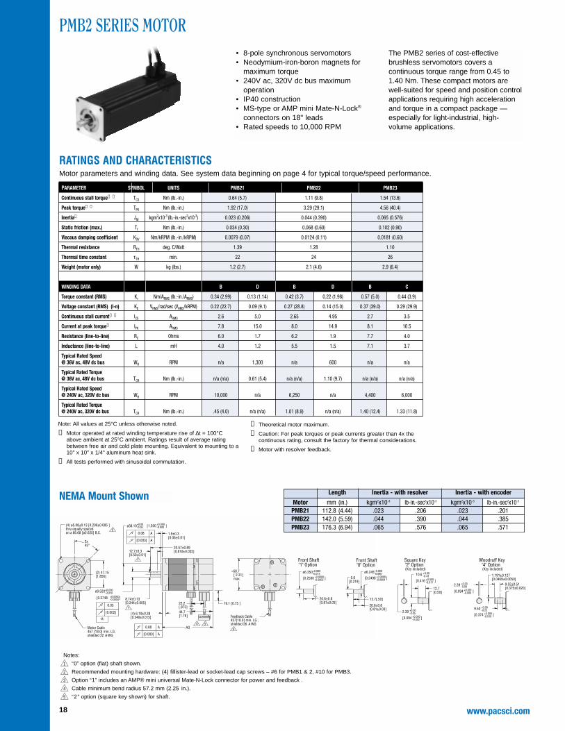
PMB2 SERIES MOTOR
NEMA Mount Shown
• 8-pole synchronous servomotors• Neodymium-iron-boron magnets for
maximum torque• 240V ac, 320V dc bus maximum
operation• IP40 construction• MS-type or AMP mini Mate-N-Lock®
connectors on 18" leads• Rated speeds to 10,000 RPM
The PMB2 series of cost-effectivebrushless servomotors covers acontinuous torque range from 0.45 to1.40 Nm. These compact motors are well-suited for speed and position controlapplications requiring high accelerationand torque in a compact package —especially for light-industrial, high-volume applications.
Notes:
1 “0” option (flat) shaft shown.
2 Recommended mounting hardware: (4) fillister-lead or socket-lead cap screws – #6 for PMB1 & 2, #10 for PMB3.
3 Option “1” includes an AMP® mini universal Mate-N-Lock connector for power and feedback .
➀ Motor operated at rated winding temperature rise of ∆t = 100°Cabove ambient at 25°C ambient. Ratings result of average ratingbetween free air and cold plate mounting. Equivalent to mounting to a10" x 10" x 1/4" aluminum heat sink.
➁ All tests performed with sinusoidal commutation.
➂ Theoretical motor maximum.
➃ Caution: For peak torques or peak currents greater than 4x thecontinuous rating, consult the factory for thermal considerations.
➄ Motor with resolver feedback.
Woodruff Key"4" Option(Key included)
9.52±0.51[0.375±0.020]
1.191±0.127[0.0469±0.0050]
2.39 +0.03-0.00
9.50 +0.00-0.25
[0.374 ]+0.000-0.010
[0.094 ]+0.001-0.000
Front Shaft"0" Option
Front Shaft"1" Option
+0.000-0.013ø6.350
[0.2500 ]+0.0000-0.0005
12.7[0.50]
2.39 +0.00-0.05
[0.094 ]+0.000-0.002
10.6 +0.00-0.43
[0.416 ]+0.000-0.017
Square Key"2" Option(Key included)+0.000
-0.090ø6.245
[0.2498 ]+0.0000-0.0004
20.6±0.8[0.81±0.03]
12.7[.50]
5.6[0.219]
20.6±0.8[0.81±0.03]
▲▲▲▲▲▲▲▲▲▲
19www.pacsci.com
AG
+0.00-0.05
+0.00-0.05
+0.00-0.43
2
5
]+0.000-0.017
]+0.000-0.002
]+0.000-0.002
+0.000-0.010
]+0.0000-0.0004
3(4) 7.87±0.38[0.310±0.015]
0.08 A
1.5±0.3[0.06±0.01]
31.75±0.89[1.250±0.035]
Feedback Cable457 [18.0] min. LG ,shielded 26 A WG
22.22±0.25[0.875±0.010]
87.4[3.44]max.
0.08 A
ø73.08
Motor Cable457 [18.0] min. LG,shielded 18 AWG
3.17
14.10
2x45°
(4) ø5.59±0.13[ 0.220±0.005] thruequally spacedon a ø98.43 [3.875] B.C.
(2) 69.6[2.740]
[0.003] A
[0.555
[0.125
[2.877
[0.003] A
ø12.695
0.05
[0.4998
[0.002]
-A-
19.1 [0.75]29.0 [1.14]
51.6 [2.03]
4 4
5 Front Shaft"O" Option
25.4[1.00]
11.9[0.469]
RATINGS AND CHARACTERISTICSMotor parameters and winding data. See system data beginning on page 4 for typical torque/speed performance.
PMB3 SERIES MOTOR
NEMA Mount Shown
• 8-pole synchronous servomotors• Neodymium-iron-boron magnets for
maximum torque• 240V ac, 320V dc bus maximum
operation• IP40 construction• MS-type or AMP mini Mate-N-Lock®
connectors on 18" lead• Rated speeds to 6,000 RPM
The PMB3 series of cost-effectivebrushless servomotors covers acontinuous torque range from 1.62 to4.84 Nm. These compact motors are well-suited for speed and position controlapplications requiring high accelerationand torque in a compact package —especially for light-industrial, high-volume applications.
Notes:
1 “0” option (flat) shaft shown.
2 Recommended mounting hardware: (4) fillister-lead or socket-lead cap screws – #6 for PMB1 & 2, #10 for PMB3.
3 Option “1” includes an AMP® mini universal Mate-N-Lock connector for power and feedback .
➀ Motor operated at rated winding temperature rise of ∆t = 100°Cabove ambient at 25°C ambient. Ratings result of average ratingbetween free air and cold plate mounting. Equivalent to mounting to a10" x 10" x 1/4" aluminum heat sink.
➁ All tests performed with sinusoidal commutation.
➂ Theoretical motor maximum.
➃ Caution: For peak torques or peak currents greater than 4x thecontinuous rating, consult the factory for thermal considerations.
Holding Brake OptionN = No brakeA = 24V dc brakeB = 100V dc brake (S30)
FactoryPreassigned
H = High voltageconstruction
Primary FeedbacksH = Hall SensorR = Size 21 frameless resolverN = No primary
Shaft SealingN = No shaft sealV = Viton shaft seal
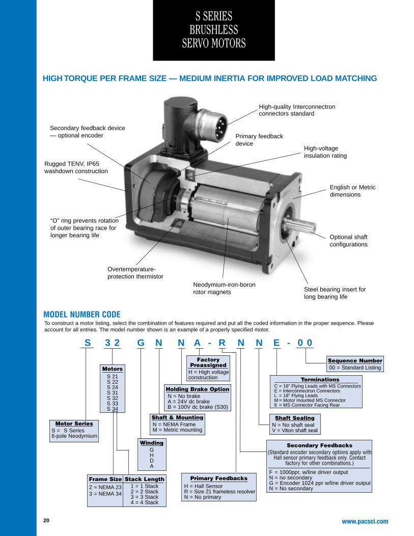
MODEL NUMBER CODETo construct a motor listing, select the combination of features required and put all the coded information in the proper sequence. Pleaseaccount for all entries. The model number shown is an example of a properly specified motor.
S 3 2 G N N A - R N N E - 0 0
TerminationsC = 18" Flying Leads with MS ConnectorsE = Interconnectron ConnectorsL = 18" Flying LeadsM = Motor mounted MS Connector6 = MS Connector Facing Rear
Rugged TENV, IP65 washdown construction
Steel bearing insert forlong bearing life
Overtemperature-protection thermistor
Optional shaftconfigurations
English or Metricdimensions
Neodymium-iron-boronrotor magnets
High-voltageinsulation rating
“O” ring prevents rotationof outer bearing race forlonger bearing life
Primary feedbackdevice
Secondary feedback device— optional encoder
High-quality Interconnectronconnectors standard
Secondary Feedbacks(Standard encoder secondary options apply with
Hall sensor primary feedback only. Contactfactory for other combinations.)
F = 1000ppr, w/line driver outputN = no secondaryG = Encoder 1024 ppr w/line driver outputN = No secondary
Sequence Number00 = Standard Listing
HIGH TORQUE PER FRAME SIZE — MEDIUM INERTIA FOR IMPROVED LOAD MATCHING
21www.pacsci.com
)2.75 70
()1.14
29(3X
.906 ± .03023.0 ± 0.76
.0982.5
(3.96)(100.6)
.41 Max.10.4
(2.25)
(57.2)
L MAX.
).315Encoder option(secondary feedback)
8(4X
4X Ø THRU,
(2X 45°)
CONNECTORPOWER
CONNECTORFEEDBACK
11 -0.001+0.012
Ø.4331 -.0000
+.0004
Ø-0.007+0.012
-.0003+.00052.3622
60
Ø 75/2.953 B.C.EQUALLY SPACED ON A
-.000+.012.228
5.8 + 0.3
ROCKFORD, ILLINOIS U.S.A.MOTOR & CONTROL DIVISION
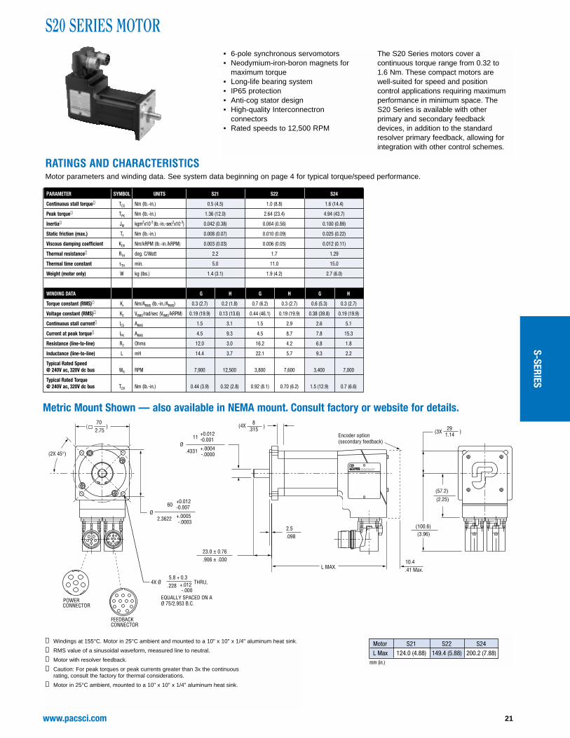
S20 SERIES MOTOR• 6-pole synchronous servomotors• Neodymium-iron-boron magnets for
The S20 Series motors cover acontinuous torque range from 0.32 to 1.6 Nm. These compact motors are well-suited for speed and position control applications requiring maximumperformance in minimum space. The S20 Series is available with otherprimary and secondary feedback devices, in addition to the standardresolver primary feedback, allowing forintegration with other control schemes.
RATINGS AND CHARACTERISTICSMotor parameters and winding data. See system data beginning on page 4 for typical torque/speed performance.
➀ Windings at 155°C. Motor in 25°C ambient and mounted to a 10" x 10" x 1/4" aluminum heat sink.
➁ RMS value of a sinusoidal waveform, measured line to neutral.
➂ Motor with resolver feedback.
➃ Caution: For peak torques or peak currents greater than 3x the continuous rating, consult the factory for thermal considerations.
➄ Motor in 25°C ambient, mounted to a 10" x 10" x 1/4" aluminum heat sink.
Metric Mount Shown — also available in NEMA mount. Consult factory or website for details.
Motor S21 S22 S24L Max 124.0 (4.88) 149.4 (5.88) 200.2 (7.88)
mm (in.)
S-SERIES
www.pacsci.com22
-.0012+.0000.1969
5 - 0.03
-.005+.000.630
16 - 0.13
.0601.50 (3.64)
(92.5)
(1.93) (49)
.787 ± .010 20 ± 0.25
Ø
(.31)(7.8)
L MAX.1.18 ± .03 30 ± 0.76
(2X 45°)
( )
CONNECTORFEEDBACKCONNECTOR
POWER
Ø 100/3.937 B.C.EQUALLY SPACED ON A
-.000+.012.276
7.0 + 0.3
14 - 0.11Ø
3.3885.8
3.1496
80
-.0003+.0005-0.007+0.012
-.0005+.0000.5512
4X Ø THRU
.22 Max.5.6
Encoder option(secondary feedback)
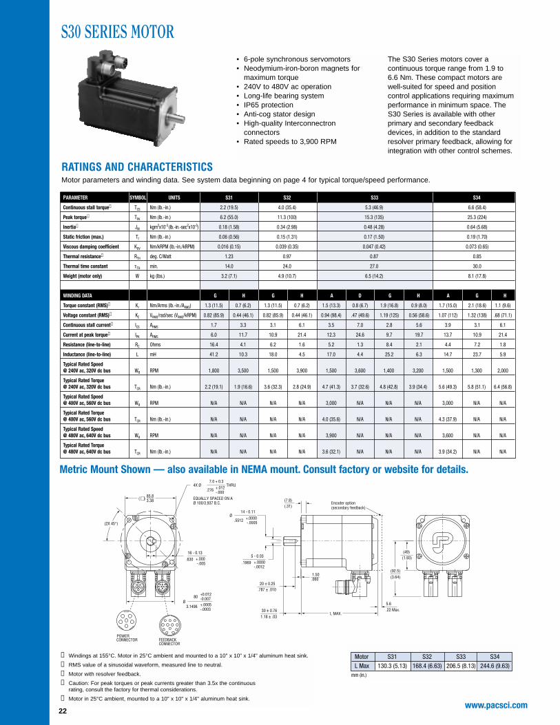
S30 SERIES MOTOR• 6-pole synchronous servomotors• Neodymium-iron-boron magnets for
maximum torque• 240V to 480V ac operation• Long-life bearing system• IP65 protection• Anti-cog stator design• High-quality Interconnectron
connectors • Rated speeds to 3,900 RPM
The S30 Series motors cover acontinuous torque range from 1.9 to6.6 Nm. These compact motors are well-suited for speed and position control applications requiring maximumperformance in minimum space. TheS30 Series is available with otherprimary and secondary feedbackdevices, in addition to the standardresolver primary feedback, allowing forintegration with other control schemes.
➀ Windings at 155°C. Motor in 25°C ambient and mounted to a 10" x 10" x 1/4" aluminum heat sink.
➁ RMS value of a sinusoidal waveform, measured line to neutral.
➂ Motor with resolver feedback.
➃ Caution: For peak torques or peak currents greater than 3.5x the continuous rating, consult the factory for thermal considerations.
➄ Motor in 25°C ambient, mounted to a 10" x 10" x 1/4" aluminum heat sink.
Metric Mount Shown — also available in NEMA mount. Consult factory or website for details.
Motor S31 S32 S33 S34L Max 130.3 (5.13) 168.4 (6.63) 206.5 (8.13) 244.6 (9.63)
mm (in.)
RATINGS AND CHARACTERISTICSMotor parameters and winding data. See system data beginning on page 4 for typical torque/speed performance.
23www.pacsci.com
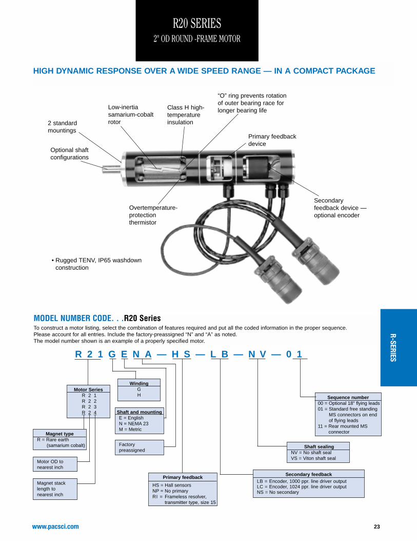
MODEL NUMBER CODE. . .R20 SeriesTo construct a motor listing, select the combination of features required and put all the coded information in the proper sequence. Please account for all entries. Include the factory-preassigned “N” and “A” as noted. The model number shown is an example of a properly specified motor.
• Rugged TENV, IP65 washdownconstruction
Overtemperature-protectionthermistor
Optional shaftconfigurations
2 standardmountings
Low-inertiasamarium-cobaltrotor
Class H high-temperatureinsulation
“O” ring prevents rotationof outer bearing race forlonger bearing life
Primary feedbackdevice
Motor SeriesR 2 1R 2 2R 2 3R 2 4
Magnet typeR = Rare earth
(samarium cobalt)
Motor OD to nearest inch
Magnet stacklength tonearest inch
WindingGH
Factorypreassigned
Shaft and mountingE = EnglishN = NEMA 23M = Metric
Primary feedback
HS = Hall sensorsNP = No primaryRI = Frameless resolver,
transmitter type, size 15
Secondary feedbackLB = Encoder, 1000 ppr. line driver outputLC = Encoder, 1024 ppr. line driver outputNS = No secondary
Shaft sealingNV = No shaft sealVS = Viton shaft seal
HIGH DYNAMIC RESPONSE OVER A WIDE SPEED RANGE — IN A COMPACT PACKAGE
R-SERIES
www.pacsci.com24
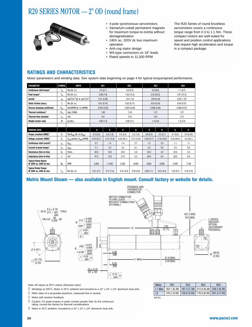
R20 SERIES MOTOR — 2" OD (round frame)• 4-pole synchronous servomotors• Samarium-cobalt permanent magnets
for maximum torque-to-inertia withoutdemagnetization
• 240V ac, 320V dc bus maximumoperation
• Anti-cog stator design• MS-type connectors on 18” leads• Rated speeds to 11,000 RPM
The R20 Series of round brushlessservomotors covers a continuous torque range from 0.3 to 1.1 Nm. Thesecompact motors are well-suited forspeed and position control applicationsthat require high acceleration and torque in a compact package.
RATINGS AND CHARACTERISTICSMotor parameters and winding data. See system data beginning on page 4 for typical torque/speed performance.
Note: All values at 25°C unless otherwise noted.
➀ Windings at 155°C. Motor in 25°C ambient and mounted to a 10" x 10" x 1/4" aluminum heat sink.
➁ RMS value of a sinusoidal waveform, measured line to neutral.
➂ Motor with resolver feedback.
➃ Caution: For peak torques or peak currents greater than 3x the continuous rating, consult the factory for thermal considerations.
➄ Motor in 25°C ambient, mounted to a 10" x 10" x 1/4" aluminum heat sink.
Metric Mount Shown — also available in English mount. Consult factory or website for details.
25www.pacsci.com
MODEL NUMBER CODE. . .R30/R40/R60/R80 SeriesTo construct a motor listing, select the combination of features required and put all the coded information in the proper sequence. Pleaseaccount for all entries. The model number shown is an example of a properly specified motor.
Rugged TENV, IP65 washdown construction
Steel bearing insert forlong bearing life
Overtemperature-protection thermistor
Optional shaftconfigurations
English or Metricdimensions,optional NEMA56C face
Low-inertia rotor
Class H high-temperatureinsulation
“O” ring prevents rotationof outer bearing race forlonger bearing life
Primary feedbackdevice
Motor Series
R 3 2 R 6 3R 3 3 R 6 5R 3 4 R 6 7R 3 5 R 8 4R 4 3 R 8 6R 4 5 R 8 8R 4 6 R 8 A
Magnet type
R = Rare earth(samarium cobalt)
Motor width to nearest inch
Magnet stacklength tonearest inchA = 10"
Winding
GHJ*K*
*R34 andR35 only
C = R30 series onlyP = R30 & R60
explosion proofseries only
A = All other series
Shaft and mountingE = EnglishM = MetricC = NEMA Face,
R40 series only
Primary feedbackHS = Hall sensorsNP = No primary R2 = Frameless resolver,
transmitter type, size 21
TS = Tachsyn
Secondary feedback
ND = Encoder, 500 ppr, line driver outputNF = Encoder, 1000 ppr, line driver outputNG = Encoder, 1024 ppr, line driver outputNS = No secondary
Shaft sealing
NV = No shaft sealVS = Viton shaft seal
Sequence number
Insert 00 if all parts are standard. Factory-assigned if any parts arecustom
R 4 3 G E N A — H S — N D — N V — 0 0
Holding brake optionN = No brakeA = 24V dc brakeB = 100V dc brake
Secondary feedback device— optional encoder
HIGH TORQUE-TO-INERTIA FOR UNMATCHED PERFORMANCE
R SERIES3.25," 4.25," 5.75," AND 7.5" SQUARE FRAME MOTORS
Rare EarthMagnetics
All motors areUL Recognized(Files E103510and E61960)
R-SERIES
www.pacsci.com26
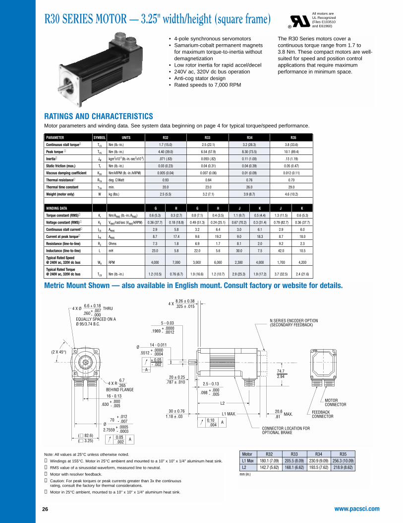
R30 SERIES MOTOR — 3.25" width/height (square frame)• 4-pole synchronous servomotors• Samarium-cobalt permanent magnets
for maximum torque-to-inertia withoutdemagnetization
• Low rotor inertia for rapid accel/decel• 240V ac, 320V dc bus operation• Anti-cog stator design• Rated speeds to 7,000 RPM
The R30 Series motors cover acontinuous torque range from 1.7 to 3.8 Nm. These compact motors are well-suited for speed and position controlapplications that require maximumperformance in minimum space.
RATINGS AND CHARACTERISTICSMotor parameters and winding data. See system data beginning on page 4 for typical torque/speed performance.
Note: All values at 25°C unless otherwise noted.
➀ Windings at 155°C. Motor in 25°C ambient and mounted to a 10" x 10" x 1/4" aluminum heat sink.
➁ RMS value of a sinusoidal waveform, measured line to neutral.
➂ Motor with resolver feedback.
➃ Caution: For peak torques or peak currents greater than 3x the continuous rating, consult the factory for thermal considerations.
➄ Motor in 25°C ambient, mounted to a 10" x 10" x 1/4" aluminum heat sink.
Metric Mount Shown — also available in English mount. Consult factory or website for details.
All motors areUL Recognized(Files E103510and E61960)
27www.pacsci.com
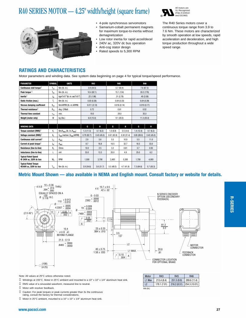
R40 SERIES MOTOR — 4.25" width/height (square frame)• 4-pole synchronous servomotors• Samarium-cobalt permanent magnets
for maximum torque-to-inertia withoutdemagnetization
• Low rotor inertia for rapid accel/decel• 240V ac, 320V dc bus operation• Anti-cog stator design• Rated speeds to 5,300 RPM
The R40 Series motors cover acontinuous torque range from 3.9 to 7.6 Nm. These motors are characterizedby smooth operation at low speeds, rapidacceleration and deceleration, and hightorque production throughout a widespeed range.
RATINGS AND CHARACTERISTICSMotor parameters and winding data. See system data beginning on page 4 for typical torque/speed performance.
Note: All values at 25°C unless otherwise noted.
➀ Windings at 155°C. Motor in 25°C ambient and mounted to a 10" x 10" x 1/4" aluminum heat sink.
➁ RMS value of a sinusoidal waveform, measured line to neutral.
➂ Motor with resolver feedback.
➃ Caution: For peak torques or peak currents greater than 3x the continuous rating, consult the factory for thermal considerations.
➄ Motor in 25°C ambient, mounted to a 10" x 10" x 1/4" aluminum heat sink.
Motor R43 R45 R46L1 Max 213.4 (8.4) 251.5 (9.9) 289.6 (11.4)L2 178.1 (7.01) 216.2 (8.51) 254.3 (10.01)
mm (in.)
Metric Mount Shown — also available in NEMA and English mount. Consult factory or website for details.
All motors areUL Recognized(Files E103510and E61960)
R-SERIES
www.pacsci.com28
R60 SERIES MOTOR — 5.75" width/height (square frame)• 4-pole synchronous servomotors• Samarium-cobalt permanent magnets
for maximum torque-to-inertia withoutdemagnetization
• Low rotor inertia for rapid accel/decel• 240V ac, 320V dc bus operation• Anti-cog stator design• Rated speeds to 6,000 RPM
The R60 Series motors cover acontinuous torque range from 8.3 to 19.9 Nm. Built for heavy duty applications,these motors deliver excellent torque,speed and/or velocity control.
RATINGS AND CHARACTERISTICSMotor parameters and winding data. See system data beginning on page 4 for typical torque/speed performance.
Note: All values at 25°C unless otherwise noted.
➀ Windings at 155°C. Motor in 25°C ambient and mounted to a 18" x 18" x 1/2" aluminum heat sink.
➁ RMS value of a sinusoidal waveform, measured line to neutral.
➂ Motor with resolver feedback.
➃ Caution: For peak torques or peak currents greater than 3x the continuous rating, consult the factory for thermal considerations.
➄ Motor in 25°C ambient, mounted to a 18" x 18" x 1/2" aluminum heat sink.
Motor R63 R65 R67L1 Max 237.7 (9.36) 288.5 (11.36) 339.3 (13.36)L2 206.2 (8.12) 257 (10.12) 307.8 (12.12)
mm (in.)
Metric Mount Shown — also available in English mount. Consult factory or website for details.
All motors areUL Recognized(Files E103510and E61960)
29www.pacsci.com
R80 SERIES MOTOR — 7.5" width/height (square frame)• 4-pole synchronous servomotors• Samarium-cobalt permanent magnets
for maximum torque-to-inertia withoutdemagnetization
• Low rotor inertia for rapid accel/decel• 240V ac, 320V dc bus operation• Anti-cog stator design• Rated speeds to 4,000 RPM
The R80 Series motors cover acontinuous torque range from 22.5 to53.4 Nm. Providing excellent torque,speed and/or velocity control, they arebuilt for extremely high torque and powerapplications.
RATINGS AND CHARACTERISTICSMotor parameters and winding data. See system data beginning on page 4 for typical torque/speed performance.
Note: All values at 25°C unless otherwise noted.
➀ Windings at 155°C. Motor in 25°C ambient and mounted to a 18" x 18" x 1/2" aluminum heat sink.
➁ RMS value of a sinusoidal waveform, measured line to neutral.
➂ Motor with resolver feedback.
➃ Caution: For peak torques or peak currents greater than 3x the continuous rating, consult the factory for thermal considerations.
➄ Motor in 25°C ambient, mounted to a 18" x 18" x 1/2" aluminum heat sink.
for maximum torque-to-inertia withoutdemagnetization
• Low rotor inertia for rapid accel/decel• 240V ac, 320V dc bus operation• Anti-cog stator design• UL Listed, file 150845. Meets UL
Division 1, Class 1, Groups C & D• Meets Cenelec requirements of
EN 50014-1992.
• Built-in thermostat• Rated speeds to 7,000 RPM
R30P Series Explosion Proof motorscover a continuous torque range from 1.3 to 3.1 Nm. These compact motors are well-suited for speed and positioncontrol applications that requiremaximum performance in minimumspace — wherever hazardous conditions are present.
RATINGS AND CHARACTERISTICSMotor parameters and winding data. See system data beginning on page 4 for typical torque/speed performance.
Note: All values at 25°C unless otherwise noted.
➀ Windings at 155°C. Motor in 25°C ambient and mounted to a 10" x 10" x 1/4" aluminum heat sink.
➁ RMS value of a sinusoidal waveform, measured line to neutral.
➂ Motor with resolver feedback.
➃ Caution: For peak torques or peak currents greater than 3x the continuous rating, consult the factory for thermal considerations.
➄ Motor in 25°C ambient, mounted to a 10" x 10" x 1/4" aluminum heat sink.
for maximum torque-to-inertia withoutdemagnetization
• Low rotor inertia for rapid accel/decel• 240V ac, 320V dc bus operation• Anti-cog stator design• UL Listed, file 150845. Meets UL
Division 1, Class 1, Groups C & D• Meets Cenelec requirements of
EN 50014-1992.
• Built-in thermostat• Rated speeds to 6,000 RPM
The R60P Series motors cover acontinuous torque range from 8.3 to 19.9 Nm. Built for heavy duty applications,these motors deliver excellent torque,speed and/or velocity control, whereverhazardous conditions are present.
RATINGS AND CHARACTERISTICSMotor parameters and winding data. See system data beginning on page 4 for typical torque/speed performance.
Note: All values at 25°C unless otherwise noted.
➀ Windings at 155°C. Motor in 25°C ambient and mounted to a 18" x 18" x 1/2" aluminum heat sink.
➁ RMS value of a sinusoidal waveform, measured line to neutral.
➂ Motor with resolver feedback.
➃ Caution: For peak torques or peak currents greater than 3x the continuous rating, consult the factory for thermal considerations.
➄ Motor in 25°C ambient, mounted to a 18" x 18" x 1/2" aluminum heat sink.
ENCODER OPTION LEADSEXIT THRU A 1/2 NPTPIPE NIPPLE
MOTOR THERMOSTAT &PRIMARY FEEDBACKLEADS EXIT THRU A1 NPT PIPE NIPPLE
1656.496 B.C.
(146)(5.75)
8 - 0.036+ .0000
16.63(4 x )
- .0014.3150
+ .0004- .0002.9449
+ 0.010- 0.00524
A
0.05.002
3.5
L2L1 MAX.
1.38
Motor R63 R65 R67L1 Max 254.8 (10.03) 305.6 (12.03) 356.4 (14.03)L2 211.6 (8.33) 262.4 (10.33) 313.2 (12.33)
mm (in.)
Metric Mount Shown — also available in English mount. Consult factory or website for details.
UL Listed file US E150845 UL/cULMeets Cenelec requirements cert. no. 99E 9844204 EE. dIIB
R-SERIES
www.pacsci.com32
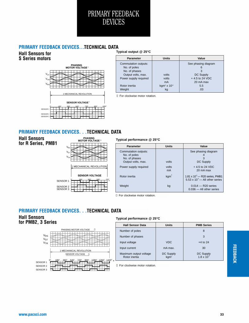
PRIMARY FEEDBACKDEVICES
Parameter Units PMA Series S Series
Frame size 21 15 21Type Transmitter Transmitter TransmitterPrimary Rotor Rotor RotorSpeed 1 1 1Input voltage VRMS 7.0 7.0 4.0Frequency kHz 10 10 5Input current, max. mA 50 65 25Transformation ratio 0.5 0.5 0.5Max. electrical error Minutes 10 10 21Rotor inertia, max. kgm2 12.3 x 10⁻⁶ 3 x 10⁻⁶ 20.3 x 10⁻⁶
Weight kg 0.22 0.06 0.21
Typical output @ 25°C
➀ For clockwise motor rotation.
R1
S2
WINDING CONFIGURATION
S4
RESOLVER
S3
S1
R2
RESOLVER OUTPUT
(SINE)
(COSINE)
VST
VRS
VTR
REVOLUTION
MOTOR VOLTAGEPHASING
1 MECHANICAL
➀
➀
FRAMELESS RESOLVERS (R)
Primary Feedback Devices Secondary Feedback DevicesPMA Series PMB Series S Series, R SeriesResolver Resolver ResolverCommutating Encoder Hall Effect Sensors Hall Effect SensorsSinCos Encoder Commutating Encoder
A selection of feedback combinations are available for the PMA, S Series and R Series motors. Options for the PMA Series include resolver,commutating encoder and SinCos encoder. The R and S Series offers either resolver or Hall effect sensors as primary feedback, and anencoder as a secondary feedback device. The PMA, R Series and S Series motors all use a resolver as feedback for system use with thePC800 and SC/SCE900 Series Drives.
Frameless Resolversfor the R Series, PMB Series motors
* Note: S2 & S4 reversed forPMB Series motors.
33www.pacsci.com
Parameter Units Value
Commutation outputs: See phasing diagramNo. of poles 6No. of phases 3Output volts, max. volts DC Supply
Power supply required volts + 4.5 to 24 VDCmA 20 mA max
Rotor inertia kgm2 x 10-6 5.5Weight kg .03
➀ For clockwise motor rotation.
Typical output @ 25°C
SENSOR 1
SENSOR 2
SENSOR 3
V
V
V
UV
VW
WU
1 MECHANICAL REVOLUTION
0° 180° 360° 540° 720° 900° 1080°
SENSOR VOLTAGE
PRIMARY FEEDBACK DEVICES. . .TECHNICAL DATAHall Sensors for S Series motors
PRIMARY FEEDBACK DEVICES. . .TECHNICAL DATA
Parameter Units Value
Commutation outputs: See phasing diagramNo. of poles 4No. of phases 3Output volts, max. volts DC Supply
Power supply required volts + 4.5 to 24 VDCmA 20 mA max
Rotor inertia kgm2
1.81 x 10⁻⁶ — R20 series, PMB15.53 x 10-3 — All other series
Weight kg 0.014 — R20 series0.036 — All other series
➀ For clockwise motor rotation.
Typical performance @ 25°C
SENSOR 1
SENSOR 2SENSOR 3
V
V
V
RS
ST
TR
1 MECHANICAL REVOLUTION
0° 180° 360° 540° 720° e
Hall Sensorsfor R Series, PMB1
PRIMARY FEEDBACKDEVICES
FEEDBACK
PRIMARY FEEDBACK DEVICES. . .TECHNICAL DATA
Hall Sensor Data Units PMB Series
Number of poles 8
Number of phases 3
Input voltage VDC +4 to 24
Input current mA max. 30
Maximum output voltage DC Supply DC SupplyRotor inertia kgm2 1.8 x 10⁻⁶
Typical performance @ 25°C
1260°1080° 1440° e900°720°
SENSOR 3
SENSOR 2
SENSOR 1
VST
VRS
VTR
0° 540°
SENSOR VOLTAGE
360°
PHASING MOTOR VOLTAGE
180°
1 MECHANICAL REVOLUTION
➀
➀
Hall Sensorsfor PMB2, 3 Series
➀ For clockwise motor rotation.
www.pacsci.com34
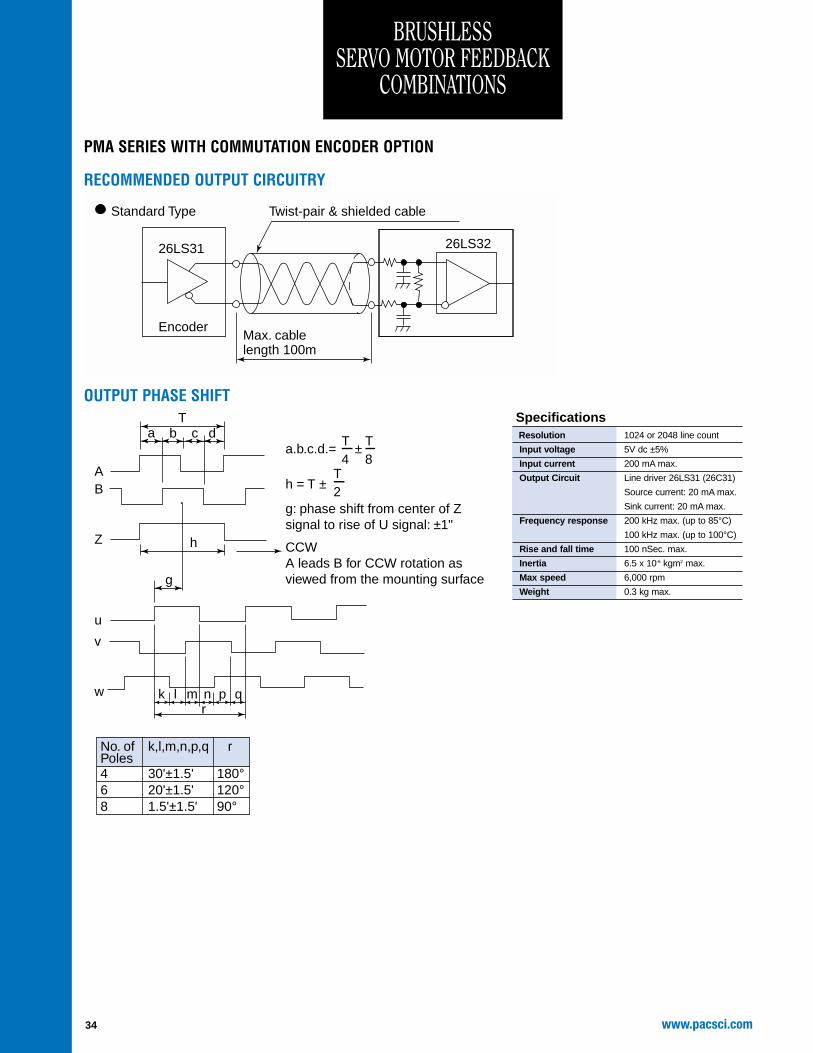
BRUSHLESS SERVO MOTOR FEEDBACK
COMBINATIONS
PMA SERIES WITH COMMUTATION ENCODER OPTION
RECOMMENDED OUTPUT CIRCUITRY
26LS31 26LS32
EncoderMax. cable length 100m
Standard Type Twist-pair & shielded cable
OUTPUT PHASE SHIFT
A
a.b.c.d.= ±T4
a
k l m n p qr
b c d
h
g
T
B
Z
u
v
w
T8
h = T ±
g: phase shift from center of Z signal to rise of U signal: ±1"
CCWA leads B for CCW rotation as viewed from the mounting surface
No. of Poles
k,l,m,n,p,q r
4 30'±1.5' 180°6 20'±1.5' 120°8 1.5'±1.5' 90°
T2
Resolution 1024 or 2048 line count
Input voltage 5V dc ±5%
Input current 200 mA max.
Output Circuit Line driver 26LS31 (26C31)
Source current: 20 mA max.
Sink current: 20 mA max.
Frequency response 200 kHz max. (up to 85°C)
100 kHz max. (up to 100°C)
Rise and fall time 100 nSec. max.
Inertia 6.5 x 10⁻⁶ kgm2 max.
Max speed 6,000 rpm
Weight 0.3 kg max.
Specifications
FEEDBACK
35www.pacsci.com
BRUSHLESS SERVO MOTOR FEEDBACK
COMBINATIONS
PMB SERIES WITH COMMUTATION ENCODER OPTION
RECOMMENDED OUTPUT CIRCUITRY
Outputs A, B, Z, U, V & W
Outputs A', B', Z', U', V' & W'AM26LS31 Output
&
OL7272 Output
OUTPUT PHASE SHIFT
Output A
Output A'
Output B
Output B'
Output Z
Output Z'
Output U
Output U'
Output V
Output V'
Output W
Output W'
Clockwise shaft rotation as viewed looking at the encoder face
120° electrical typical
240° electrical typical
Maximum Z width
90° electrical typical
180° electrical typical Resolution 2048 or 4096 line count
Input voltage 5V dc ±5%
Input current 100 mA max.
Output Circuit Line driver AM26LS31 RS422A
OL7272 high voltage line driver
TTL output
Frequency response 200 kHz
Commutation accuracy -1¡ mechanical
Inertia 1.5 x 10⁻⁴ oz-in-S2
Max speed 8,000 rpm
Specifications
36 www.pacsci.com
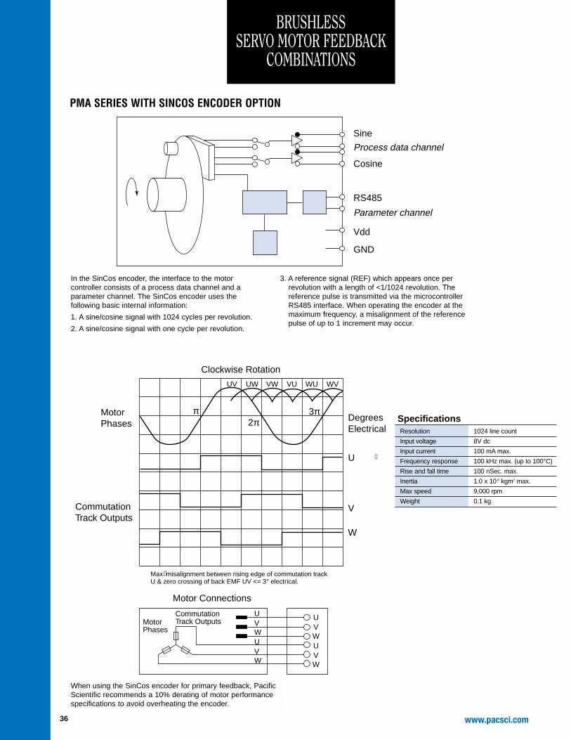
PMA SERIES WITH SINCOS ENCODER OPTION
Sine
Process data channel
Parameter channel
Cosine
RS485
Vdd
GND
In the SinCos encoder, the interface to the motorcontroller consists of a process data channel and aparameter channel. The SinCos encoder uses thefollowing basic internal information:
1. A sine/cosine signal with 1024 cycles per revolution.
2. A sine/cosine signal with one cycle per revolution.
3. A reference signal (REF) which appears once perrevolution with a length of <1/1024 revolution. Thereference pulse is transmitted via the microcontrollerRS485 interface. When operating the encoder at themaximum frequency, a misalignment of the referencepulse of up to 1 increment may occur.
Clockwise Rotation
Motor Connections
Motor Phases
UVWUVW
UVWUVW
CommutationTrack Outputs
DegreesElectrical
Max. misalignment between rising edge of commutation track U & zero crossing of back EMF UV <= 3° electrical.
U
2π
UV UW VW VU WU WV
3π
V
W
πMotorPhases
CommutationTrack Outputs
Resolution 1024 line count
Input voltage 8V dc
Input current 100 mA max.
Frequency response 100 kHz max. (up to 100°C)
Rise and fall time 100 nSec. max.
Inertia 1.0 x 10⁻⁶ kgm2 max.
Max speed 9,000 rpm
Weight 0.1 kg
Specifications
When using the SinCos encoder for primary feedback, PacificScientific recommends a 10% derating of motor performancespecifications to avoid overheating the encoder.
➀
➀
BRUSHLESS SERVO MOTOR FEEDBACK
COMBINATIONS
37www.pacsci.com
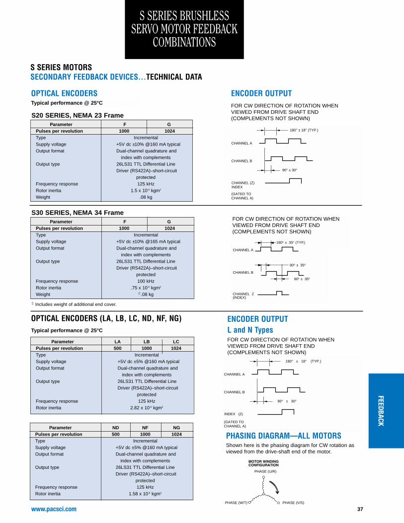
S SERIES BRUSHLESS SERVO MOTOR FEEDBACK
COMBINATIONS
ENCODER OUTPUT
Parameter F GPulses per revolution 1000 1024Type IncrementalSupply voltage +5V dc ±10% @160 mA typicalOutput format Dual-channel quadrature and
index with complementsOutput type 26LS31 TTL Differential Line
Driver (RS422A)–short-circuitprotected
Frequency response 125 kHzRotor inertia 1.5 x 10⁻⁶ kgm2
Weight .08 kg
Typical performance @ 25°C
CHANNEL A
CHANNEL B
CHANNEL (Z)INDEX
180° ± 18° (TYP.)
90° ± 30°
(GATED TOCHANNEL A)
OPTICAL ENCODERSFOR CW DIRECTION OF ROTATION WHENVIEWED FROM DRIVE SHAFT END(COMPLEMENTS NOT SHOWN)S20 SERIES, NEMA 23 Frame
Parameter F GPulses per revolution 1000 1024Type IncrementalSupply voltage +5V dc ±10% @165 mA typicalOutput format Dual-channel quadrature and
index with complementsOutput type 26LS31 TTL Differential Line
Driver (RS422A)–short-circuitprotected
Frequency response 100 kHzRotor inertia .75 x 10-6 kgm2
Weight ➀ .08 kg
S30 SERIES, NEMA 34 FrameFOR CW DIRECTION OF ROTATION WHENVIEWED FROM DRIVE SHAFT END(COMPLEMENTS NOT SHOWN)
S SERIES MOTORSSECONDARY FEEDBACK DEVICES...TECHNICAL DATA
PHASE (W/T)
PHASE (U/R)
PHASE (V/S)
PHASING DIAGRAM—ALL MOTORSShown here is the phasing diagram for CW rotation asviewed from the drive-shaft end of the motor.
➀ Includes weight of additional end cover.
ENCODER OUTPUTL and N Types
Parameter LA LB LCPulses per revolution 500 1000 1024Type IncrementalSupply voltage +5V dc ±5% @160 mA typicalOutput format Dual-channel quadrature and
index with complementsOutput type 26LS31 TTL Differential Line
Driver (RS422A)–short-circuitprotected
Frequency response 125 kHzRotor inertia 2.82 x 10⁻⁶ kgm2
Parameter ND NF NGPulses per revolution 500 1000 1024Type IncrementalSupply voltage +5V dc ±5% @160 mA typicalOutput format Dual-channel quadrature and
index with complementsOutput type 26LS31 TTL Differential Line
Driver (RS422A)–short-circuitprotected
Frequency response 125 kHzRotor inertia 1.58 x 10⁻⁶ kgm2
Typical performance @ 25°C
CHANNEL A
CHANNEL B
INDEX (Z)
180° ± 18° (TYP.)
90° ± 30°
(GATED TOCHANNEL A)
OPTICAL ENCODERS (LA, LB, LC, ND, NF, NG)
FOR CW DIRECTION OF ROTATION WHENVIEWED FROM DRIVE SHAFT END(COMPLEMENTS NOT SHOWN)
CHANNEL A
CHANNEL B
CHANNEL Z(INDEX)
180o ± 35o (TYP.)
90o ± 35o
90o ± 35o
FEEDBACK
www.pacsci.com38
Motor Brake Static Torque Nominal Torque Weight Operating Power Current Current Inertia Closing OpeningFamily Type @ 120°C @ 3,000rpm, 120°C Voltage Consumption @ 24V, 20°C @ 24V, 120°C Units x 10-3 Time Time
PMA SERIES MOTORSThe brake is intended for holding or 'parking' of a stationarymotor. It may be used for a limited number of emergency stopconditions, however such use will eventually cause wear,leading to eventual malfunction of the brake.
A PMA motor with integral brake must never be subjected touncontrolled axial forces or shocks to the motor shaft.
Contamination of the motor internal compartment by oil or otherforeign materials will result in failure of the brake. Check thesuitability of motor sealing for the working environment.
Brake data available for R Series and S Series motors. Consult factory or website for details.
BRAKE OPTIONS TECHNICAL DATA
BRAKE,CABLINGCONNECTORS
39www.pacsci.com
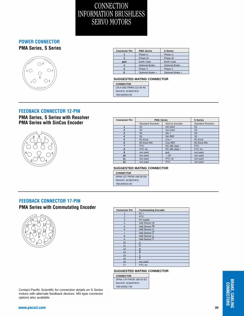
CONNECTION INFORMATION BRUSHLESS
SERVO MOTORS
Connector Pin PMA Series S Series
1 Phase U Phase U
2 Phase W Phase W
gnd Earth Case Earth Case
4 Optional Brake - Optional Brake -
5 Phase V Phase V
E Optional Brake + Optional Brake +
SUGGESTED MATING CONNECTORCONNECTOR
LPLA 06D FRRN 213 00 A5
PACIFIC SCIENTIFIC
769-004916-00
E
4
51
2
Connector Pin PMA Series S Series
Standard Resolver SinCos Encoder Standard Resolver1 S1 not used S12 S3 not used S33 S4 Sin + S44 S2 Sin REF S25 R1 Excit Cos + R1 Excit6 R2 Excit Rtn Cos REF R2 Excit Rtn7 PTC RS 485 data - PTC8 PTC rtn RS 485 data + PTC rtn9 not used gnd not used10 not used + 8V not used11 not used PTC rtn not used12 not used PTC not used
SUGGESTED MATING CONNECTORCONNECTOR
SPNA 12T FRON 169 00 D9
PACIFIC SCIENTIFIC
769-004915-00
98
12 10 27
6
113
45
1
Connector Pin Commutating Encoder1 5V +2 PTC3 0V supply4 Hall Sensor W
5 Hall Sensor W6 Hall Sensor U7 Hall Sensor U8 Hall Sensor V9 Hall Sensor V10 A11 A12 B13 B14 Z15 Z16 not used17 PTC rtn
SUGGESTED MATING CONNECTORCONNECTOR
SPNA 17H FRON 169 00 E3
PACIFIC SCIENTIFIC
769-004917-00
1211
16 13 210
89 1517P
14 3
4
567
1
Contact Pacific Scientific for connection details on S Seriesmotors with alternate feedback devices. MS-type connectoroptions also available.
POWER CONNECTORPMA Series, S Series
FEEDBACK CONNECTOR 12-PINPMA Series, S Series with ResolverPMA Series with SinCos Encoder
FEEDBACK CONNECTOR 17-PINPMA Series with Commutating Encoder
www.pacsci.com40
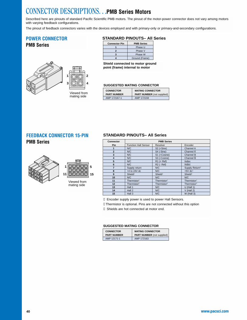
POWER CONNECTORPMB Series
SUGGESTED MATING CONNECTOR
CONNECTOR MATING CONNECTOR
PART NUMBER PART NUMBER (not supplied)
AMP 172167-1 AMP 172159
CONNECTOR DESCRIPTIONS. . .PMB Series MotorsDescribed here are pinouts of standard Pacific Scientific PMB motors. The pinout of the motor-power connector does not vary among motorswith varying feedback configurations.
The pinout of feedback connectors varies with the devices employed and with primary-only or primary-and-secondary configurations.
Connector Pin PMB Series
1 Phase U
2 Phase V
3 Phase W
4 Ground (Frame)
STANDARD PINOUTS– All Series
Shield connected to motor groundpoint (frame) internal to motor
Viewed frommating side
1
3
2
4
FEEDBACK CONNECTOR 15-PINPMB Series Connector PMB Series
13 Hall 1 N/C U (Hall 1)14 Hall 2 N/C V (Hall 2)15 Hall 3 N/C W (Hall 3)
Viewed frommating side
1
11
5
15
STANDARD PINOUTS– All Series
➀ Encoder supply power is used to power Hall Sensors.
➁ Thermistor is optional. Pins are not connected without this option
➂ Shields are hot connected at motor end.
SUGGESTED MATING CONNECTOR
CONNECTOR MATING CONNECTOR
PART NUMBER PART NUMBER (not supplied)
AMP 12171-1 AMP 172163
41www.pacsci.com
BRAKE,CABLINGCONNECTORS
PRIMARY & SECONDARYFEEDBACK CONNECTOR
Primary Feedback Secondary Feedback
Connector Hall
Pin Tachsyn Resolver Sensors Encoder
A Excitation S4 +Vdc
B Excitation RTN S3 Vdc RTN
C Phase 1 S2 Sensor 1
D Phase 2 S1 Sensor 2
E Phase 3 R1 Sensor 3
F Thermistor Thermistor Thermistor
G Encoder A
H Encoder AJ Encoder B
K Encoder BL Encoder Z
M Encoder ZN
P R2 (excitation RTN)
R Thermistor Thermistor Thermistor
S Encoder +Vdc
T Encoder Vdc RTN
SUGGESTED MATING CONNECTOR AND CLAMP
CONNECTOR CLAMP
MS3106A20-29S MS3057-12A-1
PACIFIC SCIENTIFIC PACIFIC SCIENTIFIC
P/N CZ00009 P/N CE00003
STANDARD PINOUTS–All Series
AB
C
D
EFGH
J
K
L
M
NP
R
S
T
AB
C
D
EFGH
J
K
L
M
NP
R
S
T
All SeriesExcept R20, S20, S30
R20 Series, S20, S30Only
MS3102E20-29P
MS3101A20-29P
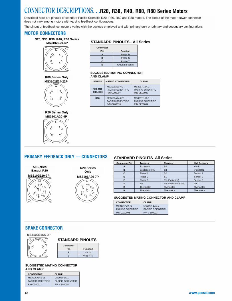
CONNECTOR DESCRIPTIONS. . .S20, S30, R20, R30, R40, R60, R80 Series MotorsDescribed here are pinouts of standard Pacific Scientific R20, R30, R40, R60 and R80 motors. The pinout of the motor-power connector doesnot vary among motors with varying feedback configurations.
The pinout of feedback connectors varies with the devices employed and with primary-only or primary-and-secondary configurations.
MOTOR AND PRIMARYFEEDBACK CONNECTOR(Available for R20 motors with primary
feedback only)
Connector Motor and Motor and
Pin Resolver Feedback Hall Sensor Feedback
A Phase R Phase R
B Phase S Phase S
C Phase T Phase T
D N/C N/C
E S4 Sensor 1
F S3 Sensor 2
G S2 Sensor 3
H S1 N/C
J N/C N/C
K Thermistor Thermistor
L Thermistor Thermistor
M N/C N/C
N Ground (Frame) Ground (Frame)
P N/C N/C
R R1 (Excitation) +V dc
S R2 (Excitation RTN) V dc RTN
T N/C N/C
SUGGESTED MATING CONNECTOR AND CLAMP
CONNECTOR CLAMP
MS3106A20-29S MS3057-12A-1
PACIFIC SCIENTIFIC PACIFIC SCIENTIFIC
P/N CZ00009 P/N CE00003
STANDARD PINOUTS
AB
C
D
EFGH
J
K
L
M
NP
R
S
T
R20 Series with rearmounted connector optionand S20 with single motor-
mounted connector
MS3102E20-29P
www.pacsci.com42
A
BC
D
A
BC
D
AB
CONNECTOR DESCRIPTIONS. . .R20, R30, R40, R60, R80 Series MotorsDescribed here are pinouts of standard Pacific Scientific R20, R30, R60 and R80 motors. The pinout of the motor-power connectordoes not vary among motors with varying feedback configurations.
The pinout of feedback connectors varies with the devices employed and with primary-only or primary-and-secondary configurations.
PRIMARY FEEDBACK ONLY — CONNECTORSConnector Pin Tachsyn Resolver Hall Sensors
A Excitation S4 +V dc
B Excitation RTN S3 V dc RTN
C Phase 1 S2 Sensor 1
D Phase 2 S1 Sensor 2
E Phase 3 R1 (Excitation) Sensor 3
F N/C R2 (Excitation RTN) N/C
G Thermistor Thermistor Thermistor
H Thermistor Thermistor Thermistor
SUGGESTED MATING CONNECTOR AND CLAMP
Connector
Pin Function
A Phase R
B Phase S
C Phase T
D Ground (Frame)
BRAKE CONNECTOR
STANDARD PINOUTSConnector
Pin Function
A +V dc
B V dc RTN
SUGGESTED MATING CONNECTORAND CLAMP
STANDARD PINOUTS–All Series
SUGGESTED MATING CONNECTOR AND CLAMPCONNECTOR CLAMP
MS3106A20-7S MS3057-12A-1
PACIFIC SCIENTIFIC PACIFIC SCIENTIFIC
P/N CZ00008 P/N CE00003
A
B
CDE
F
GH
A
B
CDE
F
GH
All SeriesExcept R20
R20 SeriesOnly
R80 Series Only
MS3102E14S-9P
MS3102E24-22P
MS3102E20-7P MS3101A20-7P
S20, S30, R30, R40, R60 SeriesMS3102E20-4P
A
BC
D
R20 Series OnlyMS3101A20-4P
STANDARD PINOUTS– All Series
43www.pacsci.com
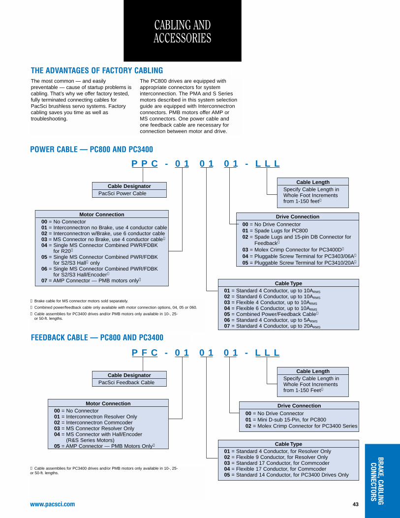
CABLING ANDACCESSORIES
BRAKE,CABLINGCONNECTORS
P P C - 0 1 0 1 0 1 - L L L
Drive Connection00 = No Drive Connector01 = Spade Lugs for PC80002 = Spade Lugs and 15-pin DB Connector for
Feedback➁
03 = Molex Crimp Connector for PC3400D➂
04 = Pluggable Screw Terminal for PC3403/06A➂
05 = Pluggable Screw Terminal for PC3410/20A➂
Cable Type01 = Standard 4 Conductor, up to 10ARMS
02 = Standard 6 Conductor, up to 10ARMS
03 = Flexible 4 Conductor, up to 10ARMS
04 = Flexible 6 Conductor, up to 10ARMS
05 = Combined Power/Feedback Cable➁
06 = Standard 4 Conductor, up to 5ARMS
07 = Standard 4 Conductor, up to 20ARMS
Cable DesignatorPacSci Power Cable
POWER CABLE — PC800 AND PC3400
Motor Connection00 = No Connector01 = Interconnectron no Brake, use 4 conductor cable02 = Interconnectron w/Brake, use 6 conductor cable03 = MS Connector no Brake, use 4 conductor cable➀
04 = Single MS Connector Combined PWR/FDBK for R20➁
05 = Single MS Connector Combined PWR/FDBK for S2/S3 Hall➁ only
06 = Single MS Connector Combined PWR/FDBK for S2/S3 Hall/Encoder➁
07 = AMP Connector — PMB motors only➂
Cable LengthSpecify Cable Length in Whole Foot Increments from 1-150 feet➂
FEEDBACK CABLE — PC800 AND PC3400
➀ Brake cable for MS connector motors sold separately.
➁ Combined power/feedback cable only available with motor connection options, 04, 05 or 060.
➂ Cable assemblies for PC3400 drives and/or PMB motors only available in 10-, 25- or 50-ft. lengths.
➀ Cable assemblies for PC3400 drives and/or PMB motors only available in 10-, 25- or 50-ft. lengths.
THE ADVANTAGES OF FACTORY CABLINGThe most common — and easilypreventable — cause of startup problems iscabling. That’s why we offer factory tested,fully terminated connecting cables forPacSci brushless servo systems. Factorycabling saves you time as well astroubleshooting.
The PC800 drives are equipped withappropriate connectors for systeminterconnection. The PMA and S Seriesmotors described in this system selectionguide are equipped with Interconnectronconnectors. PMB motors offer AMP or MS connectors. One power cable and one feedback cable are necessary forconnection between motor and drive.
P F C - 0 1 0 1 0 1 - L L L
Drive Connection00 = No Drive Connector01 = Mini D-sub 15-Pin, for PC80002 = Molex Crimp Connector for PC3400 Series
Cable Type01 = Standard 4 Conductor, for Resolver Only02 = Flexible 9 Conductor, for Resolver Only03 = Standard 17 Conductor, for Commcoder04 = Flexible 17 Conductor, for Commcoder05 = Standard 14 Conductor, for PC3400 Drives Only
Cable DesignatorPacSci Feedback Cable
Motor Connection00 = No Connector01 = Interconnectron Resolver Only02 = Interconnectron Commcoder03 = MS Connector Resolver Only04 = MS Connector with Hall/Encoder
(R&S Series Motors)05 = AMP Connector — PMB Motors Only➀
Cable LengthSpecify Cable Length in Whole Foot Increments from 1-150 Feet➀
www.pacsci.com44
➀ Flexible cable is available for High Voltage Drives.
Leave Blank for low voltage SC900 series (including SCE902)
Three digits for distance in 1 foot increments
POWER CABLE - SC/SCE900
Power Level 2 through 6
900 Series
Flexible cable
CE F - RO - XXX - 900 X
Feedback Cable
CE compliant cable
Resolver Only
Three digits for distance in 1 foot increments
FEEDBACK CABLE - SC/SCE900
A = PMA, S20’s and S30’s with Interconnectronconnectors non-flex cable
C = PMA, S20’s and S30’s with Interconnectron connectors with flex cable
900 Series
THE ADVANTAGES OF FACTORY CABLING
The most common — and easilypreventable — cause of startup problems is cabling. That’s why we offer factorytested, fully terminated connecting cablesfor PacSci brushless servo systems.Factory cabling saves you time as well astroubleshooting.
The SC/SCE900 drives are equipped with appropriate connectors for systeminterconnection. The PMA and S Seriesmotors described in this system selectionguide are equipped with Interconnectronconnectors. One power cable and one feedback cable are necessary forconnection between motor and drive.
CABLING ANDACCESSORIES
CABLING ANDACCESSORIES
RS-232 CABLE CS-232-950FOR MODEL SC/SCE950 and PC3400Use to connect SC/SCE950 servo controllersto personal computers. The 6 foot RS-232 cableconnects 9-pin SC/SCE950 connector (J58 port)to PC’s 9-pin serial port. Includes 9 to 25-pinadaptor for PCs with 25-pin serial port.
HOW TO ORDER. . . . . .Model numberRS-232 cable CS-232-950
Order these accessories to simplifyinstallation, startup and programmingof your Pacific Scientific step motorand servo motor controls.
PACLAN DATA CABLETwinaxial transmission cable. Use withSC/SCE950 to interconnect LAN nodes fordigital communications up to 500 feet. Jacketis blue PVC.
SpecificationsUse with SC/SCE950 . . . .25 AWG
(7/33 stranded)124 Ohmcharacteristicimpedance 60°C,UL Style 2092Passes VW-1vertical wireflame test
Drive Cable Length Filter Supplier
SCE902 Up to 50 meters 25CE4 MTE Corporation➀ Tel# 414-253-8200
SCE903 Up to 10 Meters None ➁
SCE904 Up to 10 Meters None ➁
SCE905 Up to 10 Meters None ➁
SCE906 Up to 10 Meters None ➁ ➂
➀ Recommended filter not supplied by Pacific Scientific.
➁ No filter is required with a single axis at designated cable lengths. Filtering may be required for multi-axis configurations or longer cable lengths. Consult factory for more information.
➂ A 3-phase line inductor with a minimum of 1.17mH is required to comply with CE. Consult Factory for more information.
RECOMMENDED FILTERING FORCE COMPLIANCEThere are many applications for machines todaywhich require filtering to reduce electrical noise.Filters may be necessary to comply with thestandards of the global regulatory groups, orjust to have piece of mind for reliable machineoperation. The SCE900 drives have beendesigned with this in mind. The table belowsummarizes the conditions under which filteringis required to meet the standards for CEcompliance: