SERl/TP-231-2294 UC Category: 62a High-Temperature Solar Thermal Energy Storage Werner Luft April 1984 To be submitted to International Journal of Solar Energy Prepared under Task No. 1377.10 FTP No. 455-84 Solar Energy Research Institute A Division of Midwest Research Institute 1617 Cole Boulevard Golden, Colorado 80401 Prepared for the U.S. Department of Energy Contract No. DE-AC02-83CH10093
Transcript
SERl/TP-231-2294
UC Category: 62a
High-Temperature Solar Thermal Energy Storage
Werner Luft
April 1984
To be submitted to
International Journal of Solar Energy
Prepared under Task No. 1377.10
FTP No. 455-84
Solar Energy Research Institute A Division of Midwest Research Institute
1617 Cole Boulevard
Golden, Colorado 80401
Prepared for the
U.S. Department of Energy Contract No. DE-AC02-83CH10093
NOTICE
This report was prepared as an account of work sponsored by the United States Government. Neither the United States nor the United States Department of Energy,
nor any of their employees, nor any of their contractors, subcontractors, or their employees, makes any warranty, express or implied, or assumes any legal liability
or responsibility for the accuracy, completeness or usefulness of any information, apparatus, product or process disclosed, or represents that its use would not
infringe privately owned rights.
TP-2294
1
HIGH-TEMPERATURE SOLAR THERMAL ENERGY STORAGE
by
Werner Luft
Solar Energy Research Institute
ABSTRACT
The mislocation of solar energy production facilities and points of demand and the temporal mismatch of solar energy availability and energy demand make transport and storage of solar energy essential. Research at the Solar Energy Research Institute has focused on high-temperature, diurnal storage because of the frequency of use and the potential for conservation of premium fossil fuels. Also, high-temperature thermal energy storage can reduce the cost of hydrogen production, electricity and heat produced by cogeneration, and methane reforming. SERI research is concentrating on containment techniques (including materials corrosion, internal insulation, and storage medium for high-temperature molten salts) and direct-contact heat exchange (including costeffective heat exchanger design and heat transfer of various materials). After initial screening tests we selected carbonates for further study. We are now constructing test equipment that will allow heat transfer experiments with molten carbonate to 700° c.
INTRODUCTION
In the next IO to 20 years, the real cost of energy will rise primarily as a result of the increasing difficulty in obtaining liquid, portable fuels such as gasoline and fuel oil. This situation will be further aggravated because the continued use of fossil fuels is detrimental to the environment through production of high levels of carbon monoxide and nitrogen oxides. The resultant societal and economic presures will provide an everincreasing incentive for the timely development of more efficient methods of converting and storing energy, thus improving the management of national energy resources.
The mislocation of solar energy production facilities and points of energy demand and the mismatch of solar energy availability and the period of energy demand make transport and storage of solar energy essential (Escher 1983). Thermal energy storage adds cost to a solar thermal energy system. However, it has been shown that when the cost of solar energy without storage is less than the corresponding energy from fossil fuels, then storage (up to some limit, generally at least 15 hours) reduces the overall cost for capital investment and operation for each unit of useful energy output delivered to the user from the total solar energy system (Copeland et al. 1983).
Favorable insolation areas, suitable for large-scale solar energy production, are located remote from energy users, who tend to be located in areas of higher population density. Thus, energy transport is required between source and user. Similarly, maximum solar energy availability occurs during the middle of the day, whereas industrial process heat is required 8 to 24 hours per day. Reliable energy storage compensates for this inconsistency by extending solar applications to loads which are not coincident with solar radiation availability. Consequently, energy storage is vital if solar energy is to meet a large fraction of the total energy needs of the nation. A major portion of the total U.S. energy demand is for either electric power or industrial process heat. As much as 60% of the
TP-2294
2
potential solar thermal energy supplied to these markets could advantageously use storage. In addition, thermal storage technologies are expected to be instrumental in the production of fuels and chemicals by solar energy in the next several decades.
By the year 2000, about one third of a quad (0.3 EJ) per year of solar thermal electricity production (Department of Energy n.d.) and one-half to one quad (0.5-1 EJ) per year of industrial process heat could be furnished by solar energy if the systems used thermal storage (Edelstein 1982). In the year 2000, the value of 1 quad (1 EJ) of energy in 1980 dollars is about $5 billion. Thus, a research investment on the order of $10 million in solar thermal energy storage to achieve about 0.8 to 1.3 quads per year of extra solar energy represents only 0.2% of the annual cost for the additional energy that the research made possible.
TYPES OF SOLAR THERMAL STORAGE
Thermal storage can be divided into three groups of varying storage duration: (1) buffer· storage (15-60 minutes), (2) diurnal storage (1-24 hours) and, (3) long-duration storage (greater than 1 day).
Depending on the output temperature of the storage medium and the temperature required by the users of the stored energy, each of these storage groups is at a specific stage of development as shown in Table 1.
Table I. Technology Status in Energy Storage and Transport
Buffer c D D R R Diurnal c D D R R Long-duration D R R R R
C=Commercial, D=Development, R=Research
Buffer storage systems have been developed for applications using temperatures below 55o0c, and limited work has been done on focally mounted receivers on parabolic dishes for higher temperatures. Diurnal storage systems below °550 c are under development.However, certain supporting technologies, such as direct-contact heat exchange, need additional research. In long-duration storage, only ice, chilled water, hot water, and
°solar pond storage at less than 100 c, are being developed.
More research is needed on buff er and diurnal storage technologies that allow thermal energy storage above 055o c for industrial process heat, electric power generation, andproduction of fuels and chemicals. Research is also needed on long-duration storage for all temperatures above °100 c. Research at the Solar Energy Research Institute has focused on diurnal storage for two reasons: (1) the size of the potential market, and (2) the cost of solar energy storage as discussed below.
TP-2294
3
Nearly all users of solar-generated industrial process heat, whether they operate one, two, or three shifts, require diurnal storage, unless solar energy is only used to complemen t heat from fossil fuels. Electric utilities operate their baseload plants for 24 hours per day. Thus, solar energy used for baseloads requires diurnal storage. If solar energy is used for intermediate loads that coincide with daylight hours of high insolation, little or no diurnal thermal energy storage is required; however, if needs for peak loads are to be met by solar energy, diurnal storage is required. Solar energy would first be economic for providing peak loads that now require the use of fuel oil rather than relatively inexpensive coal. Consequently, solar energy diurnal storage would be required.
The overall needs for heat and electricity in the United States can be seen from the energy flow diagram in Figure 1 (Department of Energy 1982). The total energy consumed by electric utilities in 1981 was about 24.6 quads (25 EJ), and about 29 quads (29 EJ) were consumed by industry (Department of Energy 1982). About 2.2 quads of the 24.6 quads consumed by the electric utilities were provided by oil and 3.8 quads by natural gas (Solar Energy Research Institute 1983). Of the 29 quads of energy used by industry, about 10.7 quads (11 EJ) were used for process heat (Iannucci 1981), 3 quadswere supplied as electric energy, and the balance was supplied as chemical enerWr. Ofthe 10.7 quads for process heat, 5.6 quads were used at temp�atures below 650 C and
° °1.9 quads were used for the temperature range 650 -1100 c (Iannucci 1981). Methanereforming to make hydrogen for ammonia and for other chemical uses consumed 1.2 quads of energy (Rozeman 1980).
Some portion of the overall energy consumption is projected to be supplied by solar energy in the year 2000. For example, 1 quad of thermal energy is the projected amount to be supplied to electric utilities by solar energy (Department of Energy n.d.); 2 quads is the projected amount of industrial process heat under 60o0c provided by solar energy, and O .36 quads is the potential amount of solar thermal energy to replace methane in production of chemicals. A portion of the projected energy consumption would be
°supplied by high-temperature (650 -9oo0c) solar energy. ·
The second reason for our concentration on diurnal storage is because long-duration thermal energy storage at high temperature becomes expensive. Diurnal storage is used every day. Long-duration storage is used less frequently. As the storage duration increases, the usage frequency decreases. For example, 7 days of stored energy is used much less frequently than 2 days of stored energy. The storage system cost is thus spread over smaller and smaller amounts of energy per unit of time. Backup plants using fossil fuel then provide energy more economically for the few occasions when there is inadequate solar energy available. It was deemed important to concentrate our research on those energy storage applications that promise to become economic at the earliest time.
0Since technologies for diurnal thermal energy storage at temperatures below 55o c arealready in development (as shown in Table 1) and therefore are past the research stage, we are addressing the next temperature range. Specifically, we are researching thermal
0energy storage technologies for temperatures above 80o c.
TP-2294
4
RATIONALE
°The rationale for concentrating on storage above 800 c is:
1. The DOE Solar Thermal Technology Division has shifted its research and development emphasis toward high-temperature solar central receivers for improved energyconversion efficiency. Our solar energy storage research is in support of this work.
2. High-temperature energy storage provides the potential for significant conservation°of premium fossil fuels. The requirement for industrial process heat between 650 C
0and l 10o c in the United States is approximately 1.9 quads (1.9 EJ) per year.Storage at high temperatures would allow a significant part of that heat to beprovided by solar energy (Iannucci 1981).
3. The production costs for hydrogen using solar energy may be reduced by 25% when°using high-temperature (950 C) thermal energy storage as compared to the same
processwithout storage (Copeland et al. 1982).
4. The cost of solar electric power generation may be red,vced by 12% by using acombined Brayton/Rankine cycle as compared to a Ranldne cycle only (Copeland
° °1982). The combined cycle requires a temperature of 1100 c as compared to 5 l 0 cfor the Rankine cycle.
5. Cogeneration of heat and electricity by solar energy becomes attractive at high0temperatures (above 90o c). Cogeneration represents a large potential market. In
1981 the amount of electricity purchased by industry in the United States was2.8 quads. In addition, industry used 10.6 quads of heat for processes, 6.5 quads of
°which were provided at 650 c or lower temperatures. A part of this electricity andheat could be provided by cogeneration using solar energy. Solar cogenerationbecomes more economically attractive as the cost of electricity generated withfossil fuels increases.
The reason that cogeneration by solar energy requires high temperatures to become 0economic is the following. To provide 54o c process heat and electricity with
conventional fossil fuels, Brayton cycle turbines or diesel engines connected to electric generators are used. Both systems provide about 20% electric energy and 80% heat at 540°c. Solar energy would compete against these oil-fueled systems. Current solar central receivers (water/steam, molten nitrate, and liquid sodium are used as working fluids) and storage, which are limited to about sso0c, could provide both
°electric power (using a Rankine cycle engine with an electric generator) and 540 Cheat; however, they cannot produce both the electrici� and the heat in one cyclebecause the exhaust heat from the Rankine cycle is 100 C or less. Thus, part of the solar energy has to be used to run the Rankine cycle engine to produce electric
0power, and another part has to be used to provide 54o c heat for processes.
°By using high-temperature (above 900 c) solar central receiver systems and energy0storage, Brayton-cycle engines could be run and their exhaust (at 54o c) used for
process heat. The high-temperature solar system would only have to be 65%-70% °the size of a lower-temperature (540 C) solar system while providing the same
°amount of electricity and 540 c process heat. Thus, significant cost savings wouldbe achieved when using the high-temperature solar energy systems as compared to
°540 c nitrate salt solar energy systems.
°6. Methane reforming (at 790 c) to produce synthesis gas (H and CO) to use in pro2 ducing basic building blocks for many organic compounds (alcohols and hydrocarbons)
° 0also requires high storage temperatures (850 -9oo c). The energy usage formethane reforming in 1980 was about 1.24 quads (Rozeman 1980); 40% of that energy was used as heat and the remainder was the chemical energy bound in the product. It is estimated that about 29% of the energy for methane reforming could be provided from solar energy if energy storage is used.
Thus, to recapitulate, high-temperature solar thermal energy storage could be used in the following applications:
• Process heat in industry
• Production of hydrogen
• Electric power generation
• Cogeneration of heat and electricity
• Methane reforming.
GOALS
The goal of our research of solar thermal energy storage at the Solar Energy Research Institute is to identify economical energy storage and transport subsystems for the industrial sector of the U .s. economy and to bring the appropriate technologies to the point where they can be transferred from research to development.
Research would end at the point where concept feasibility and proof of concept have been established in the laboratory and on subscale models. Development work to provide technical feasibility on full-scale models would follow the research activities.
The requirements that the energy storage must be economical mean that the cost of solar energy storage must be less than the value of the stored energy. The value of energy storage for industrial process heat in 1990 is projected to be about $10 to $25/kWh of thermal storage capacity (in 1980 dollars) (Hock and Karpuk 1981) and for electric power applications $37 to $125/kWh or $12 to $41/kWh (in 1980 dollars). Thesee t values are for a 100-MW plant and depend on the storage duration. The lowest value corresponds to 15 hours of storage and the highest value to 3 hours of storage because shorter-duration storage is used more frequently than longer-duration storage (Luft and Copeland 1983). The value of storage for electric power applications decreases with plant size. A reasonable value for large, more efficient plants is $25/kWh "t
RESEARCH AREAS Two aspects of high-temperature thermal energy storage are being investigated at the Solar Energy Research Institute: (1) containment techniques and (2) direct-contact heat exchange. Economic containment of the high-temperature energy storage medium is central to the concept of high-temperature storage. However, in addition to containment, one must be able to remove the heat from the storage medium and transfer it to the process medium, which is frequently air, hence the need for heat exchange.
TP-2294
5
TP-2294
6
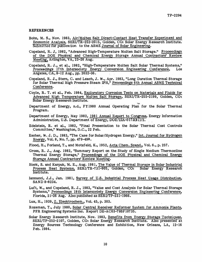
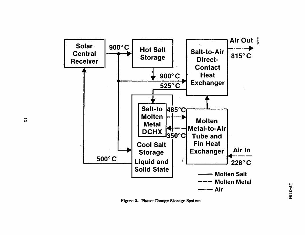
The simplest heat exchange system is illustrated in Figure 2. In this case, the medium being heated in the solar central receiver is the same as that being stored. In more complex systems, additional media may be used for storage and heat transfer. Figure 3 shows a system that uses phase changes of the storage medium (salt in this case) and that has three heat exchangers: two direct-contact heat exchangers for salt/air and salt/ molten metal exchange, and one conventional tube-and-fin heat exchanger between air and molten metal. Depending on the overall solar thermal energy system, the heat exchanger(s) may be regarded as a part of the energy storage subsystem or a subsystem in its own right.
KEY TECHNICAL ISSUES
The following key technical issues must be resolved to achieve the research goals.
For high-temperature molten-salt containment, the issues are:
• Materials corrosion, especially of the containment tank structure and internal insulation. The need for a long life and minimal replacemeqt costs permits only verylow rates of material degradstion.
• Conceptual design of internal insulation and its implementation.
• Cost of the storage medium. This cost can represent a considerable fraction of thetotal storage subsystem cost.
• Handling of the storage medium (pumps and controls).
• Design of inlet and outlet piping for the storage medium.
For high-temperature direct-contact heat exchange, the issues are:
• Cost-effective heat exchanger design for various applications with low pumpingpower requirements.
• Heat transfer performance.
• Construction materials for various heat transfer salts.
• Operational problems associated with the equipment.
RESEARCH STATUS
. High-Temperature Molten-Salt Containment
° °Systems analyses at SERI have shown that high-temperature (800 -1100 c) molten saltsare potentially attractive both as receiver coolants and as storage media. The salts could be sodium hydroxide, carbonates, or chlorides. They are all inexpensive and stable up to l 10o0c. The problems witla nigh-temperature salt storage are how to contain the hot salt, how to achieve high storage efficiency, and how to accomplish the containment and high efficiency storage in a cost-effective manner.
One approach to solving these problems is to use a single-tank thermocline storage subsystem, submerged internal insulation, and an insulating platform floating at the
TP-2294
7
thermocline between the hot and cold salt. Internal insulation in the storage tank ensures that the structural members of the containment tank will be at a low temperature, thus allowing use of low-cost iron-based alloys or concrete. The tank would be designed for a 2% daily heat loss so that the temperature drop through the insulation gives a temperature of 35o0c at the structural tank wall. One internal insulation approach is to employ non-load-bearing, salt-compatible materials to prevent natural convection in the salt, i.e., to employ salt as the insulation. Trapped molten salt within the internal insulation structure acts as insulation. The single-tank concept ensures that the liquid level in the tank is constant. Thus, hot salt entering the tank cannot flow directly through the insulation to the tank wall. If hot salt were allowed to do so, it would heat the tank wall beyond allowable limits. Two-tank systems are also considered; they require an insulation that is not penetrated by the molten salt.
A number of mechanisms potentially degrade a thermocline. At the high temperatures involved here, there is also a considerable radiation heat exchange from the hot salt and wall insulation at the top of the tank to the cooler salt at the bottom. Many of these degradation mechanisms would be eliminated or reduced by the use of a free-floating insulating platform between the hot and cool salt regions. The platform would ensure a sharp thermocline and, thus, high storage efficiency.
In the past two years we have addressed three of the key issues: materials corrosion, design concepts for the internal insulation, and feasibility of the floating platform concept.
The free-floating platform concept was investigated for dynamic stability and the effect of its thermal conductivity on storage effectiveness. We found that the concept works.
° 0At small density differences, such as between water at 25 and 6o c, a platform can bemade to float at the thermocline. Thus, a floating platform should be able to float
° °between hot (900 c) and cooler (4S0 c) salt. Such a thermocline is more stable-particularly at high flow rates-and more effective than a natural thermocline (no insulating layer). The floating platform suppresses many mechanisms that tend to degrade a natural thermocline, such as (1) convective motion induced by heat transfer from the hot layer to the cold layer via the highly thermally conductive tank walls, (2} mixing during charge or discharge when the thermocline region is near the inlet or outlet, and (3) thermal diffusion from the hot layer to the cold layer (Gross 1982).
We have identified over 10 design concepts for the internal insulation and are now conducting economic assessments of these concepts to select the most promising for further research.
Corrosion tests have been performed on a large number of metal alloys and ceramics (Coyle 1984}. The initial screening tests showed that of hydroxides (NaOH), chlorides (Na,K,Mg}Cl, and carbonates (Na,K) co , the carbonates resulted in the least corrosion2 3of alloys, whereas the chlorides were least corrosive to ceramics. On the basis of the screening tests, we selected carbonates for further study. Because of the need for a relatively low melting point to minimize freezing problems in pipes and valves, we selected the ternary eutectic (Li,Na,K) co for additional corrosion tests. This ternary2 3 °eutectic has a melting point of 392 c. However, this carbonate salt is relatively expensive ($1.03/kg) because of the lithium content. For 1800 M Wh storage capacity, the ternary eutectic carbonate material cost alone represents 48% of the total subsystem cost. Additional corrosion tests on metal alloys have been done using the ternary eutectic. These tests were made with a 0.4% and a 10% carbon dioxide atmosphere over the salt to control its basicity in the Lux-Flood acid-base scheme (Lux 1939; Flood et al. 1952).
TP-2294
8
Only two of the alloys tested to date have acceptable corrosion characteristics, viz., Inconel 600 and Hastelloy N. The average corrosion rates measured between 15 and 60
0days of exposure at 90o c are shown in Table 2.
Table 2. Summary (Na,K,Li}2of co3 Corrosion at Test Results in Eutectic
09oo c
Maximum Exposure Calculated Corrosion Metal Alloy Time (days) Rate (mm/yr)
Hastelloy N 60 0.2
Ni Al 10 greater than 10 3Haynes 556 6 a
Inconel 600 60 0.4
aunacceptable delamination.
High-Temperature Direct-Contact Heat Excba.nge System studies had shown that direct-contact heat exchangers offer the potential for large cost reductions in solar thermal heat exchange and storage systems where one of the working fluids is a gas. By bringing two immiscible, nonreacting fluids into direct contact, heat transfer can occur across the phase boundaries rather than across a separating metal wall. Elimination of a separating metal wall between the two phases not only improves the process thermodynamically, but also enhances the process economics because much less metal is required. At temperatures above 600°c, conventional heatexchangers would require exotic metals or ceramics, leading to very high costs for the heat exchanger. A direct-contact heat exchanger using a packed column could be constructed out of conventional steel alloys with refractory lining and use ceramic packing
°for very high temperature (above 600 c) service; it would be less costly. An alternativewould be to use a spray tower direct-contact heat exchanger that would also eliminate the cost for the packing.
Although use of direct-contact heat exchangers would allow major reductions in the cost of storage systems in which air is a working fluid, there was little operational experience or design information available when we started our research in 1982. The practice for design of air/liquid direct-contact heat exchangers is based on analogies to mass transfer processes in packed columns encountered in the chemical industry.
0Over the past one and one-half years, we performed tests conducted an economic analysis for the temperature ran3with nitrate salts at 35o c and
0 0e of 35o -aoo c. Volumetric0heat transfer coefficients in the range of 2000-3000 W/m c were measured at air flow
rates of 30 to 50 kg/h. The salt flow rate had no significant impact on the heat transfer coefficient. With Rashig rings used as a packing, the heat transfer varies as the 1.28 power of the air flow rate (Bohn 1983). Pall ring packings gave about one-half the air pressure drop over the packed column than did Rashig rings. Low pressure drop is important because the power for moving the air across the packed column can easily increase the operating cost to a point that could make direct-contact heat exchange uneconomical.
TP-2294
9
An economic analysis based on the test data showed that direct-contact heat exchangers cost about one-half as much as finned-tube heat exchangers over the temperature range 3500 0 0-55ooc and about one-fourth to one-fifth as much at soo c-soo c. The ratio wasinfluenced by the operating pressure of the system (Bohn 1983).
RESEARCH PLANS
In the area of molten-salt containment, we plan to conduct an economic evaluation and technical feasibility assessment of a number of design concepts for internal insulation. The most attractive of the concepts will be selected for further work. A detailed design will be made of the concept, and hardware will be fabricated. The insulation will then be tested for thermal conductivity in molten carbonate. In parallel with the hardware effort, we will construct a mathematical model of the selected insulation concept to permit us to predict the performance of the actual hardware insulation. The predicted values will be compared to the test results, and the model will be modified as required. Another parallel effort will be in the materials area. Five issues will be addressed: (1) the influence of the basicity of the salt on the corrosion of metal alloys and means to controlling the salt chemistry by providing the proper at�sphere around the salt, (2) means of reducing the cost of the salt while maintaining a ·1ow melting point (below
0soo c), (3) measurement of physical properties, such as heat capacity and thermalconductivity, that are not available in the literature for the particular salt composition chosen, (4) the effect of temperature on the corrosion rate, and (5) long-term corrosion effects.
The total effort will culminate in the construcjion of a subscale thermal storage subsystem with the storage volume of about 1 m • This subsystem will be subjected to performance tests.
In the direct-contact heat exchange area, we are now constructing test equipment that 0will allow heat-transfer experiments with molten carbonate to perhaps 70o c. Tests at
such elevated temperature will allow us to establish the role of radiation heat transfer in the overall direct-contact heat exchange. Using the test loop we will measure column inlet and outlet salt and air temperatures and salt and air flow rates. Air and salt flow rates will be consistent with Pall rings, which have been recognized as the most efficient packing for heat transfer duty. Tests are planned for a variety of packings, including ceramic packings, to permit assessment of the effect of packing conductivity on the heat exchange. We expect to obtain sufficient data to establish the feasibility and economics of direct-contact heat exchangers over a wide range of temperatures. The resulting heat transfer data will be used to verify or, if necessary, modify the economic analyses developed in 1983. Subsequent research will focus on fundamental heat transfer and materials studies.
ACKNOWLEDGEMENTS
I want to thank Drs. Robert J. Copeland, R. Gerald Nix, and Mark S. Bohn, all at the Solar Energy Research Institute, for their advice and useful discussions that made this paper possible.
TP-2294
10
REFERENCES
Bohn, M. s., Nov. 1983, Air/Molten Salt Direct-Contact Heat Transfer Experiment and Economic Analysis, SERI/TR-252-2015, Golden, CO: Solar Energy Research Institute. Submitted for publication to the ASME Journal of Solar Engineering.
Copeland, R. J, 1982, "Advanced High-Temperature Molten Salt Storage." Proceedings of the DOE Physical and Chemical Energy Storage Annual Contractors' Review Meeting, Arlington, VA, 23-26 Aug.
Copeland, R. J ., et al., 1982, "High-Temperature Molten Salt Solar Thermal Systems," Proceedings 17th Intersociety Energy Conversion Engineering Conference, Los Angeles, CA, 8-12 Aug., pp. 2032-36.
Copeland, R. J., Stern, c. and Leach, J. W., Apr. 1983, "Long Duration Thermal Storage for Solar Thermal High Pressure Steam IPH," Proceedings 6th Annual ASME Technical Conference.
Coyle, R. T. et al., Feb. 1984, Exploratory Corrosion Tests on Materials and Fluids for Advanced High Temperature Molten Salt Storage, SERI/TR-255-2199, Golden, CO: Solar Energy Research Instituteo
=
Department of Energy, n.d., FY1980 Annual Operating Plan for the Solar Thermal Program.
Department of Energy, May 1982, 1981 Annual Report to Con ess,, Energy InformationAdministration, U.S. Department of Energy, DOE/EIA-0173(81
T)'/2.
Edelstein, R. et al., 1982, "Final Presentation to the Solar Thermal Cost Controls Committee," Washington, D.C., 22 Feb.
Escher, W. J. D., 1983, "The Case for Solar/Hydrogen Energy," Int. Journal for Hydrogen Energy, Vol. 8, No. 7, pp. 479-498.
Flood, H., For land, T ., and Motzf eld, K., 1952, Acta Chem. Scand., Vol. 6 ., p. 257.
Gross, R. J., Aug. 1982, "Summary Report on the Study of Single Medium Thermocline Thermal Energy Storage," Proceedings of the DOE Physical and Chemical Energy Storage Annual Contractors' Review Meeting.
Hock, S. and Karpuk, M. E., Aug. 1981, The Value of Thermal Storage in Solar Industrial Process Heat Systems, SERI/TR-731-905, Golden, CO: Solar Energy Research Institute.
Iannucci, J.J., Jan. 1981, Survey of U.S. Industrial Process Heat Usage Distribution, SAND 8-8234.
Luft, W., and Copeland, R. J., 1983, "Value and Cost Analysis for Solar Thermal Storage Systems," Proceedings 18th Intersociety Energy Conversion Engineering Conference, Florida, 21-26 Aug. Also published as SERI/TP-231-1966.
Lux, H., 1939, z. Elecktrochem., Vol. 45, p. 303.
Rozeman, T ., July 1980, Solar Central Receiver Reformer System for Ammonia Plants, PFR Engineering Systems Inc. Report DE-AC03-79SF10735.
Solar Energy Research Institute, Nov. 1983, Benefits from Energy Storage Techniques, SERI/TP-252-2107, Golden, CO: Solar Energy Research Institute. Also presented at Energy Sources Technology Conference and Exhibition, New Orleans, LA, 12-16 Feb. 1984.
Coal
Hydropower 2. 73
Nuclear Power 2.90
Net Exports 2.92
Energy Production
64.96 Natural Gas 20.10
�
Natural Gas Net Imports
0.85
Crude Oil and Lease Condensate
18.13
Petroleum Net Imports
11.39
Energy Conversion and Consumed at Transmission Losses
Electric Utilities 17.42 Residential and
Commercial 24.63
Natural Gas Plant Liquids
2.27
Residential and l 25.64 Total Commercial 15.07 Energy
Net Indus- Consumed
Industrial Energy trial 73.91
22.22 Consumed 29.02
Transportation
19.20
�
56.49
Transportation 19.22
Figure I. Diagram of Energy Flow in the United States in 1981 (in quadrillion Btu)
'" x '.:; '.:J "'
--
� I
I:.;> t.;> e,o "'"'
Solar Central
.... Hot Salt ....
Storage Receiver
... � �r ... Salt-to-Air
...
Direct-Contact
Cold Salt ..... Heat
Storage ...... Exchanger
Figure 2. Solar Energy System Usi� One Heat Transfer and Storage Medium
....
Ill""
Air 0 ut
,....
......
Air In
...... N
� 'P 1:-.:1 1:-.:1 CD """
1 •Air Out �g
Solar Central
Receiver
i
900°C ...... ..
..
Hot Salt Storage
Salt-to-Air r-·-·-+ 81 5° C
• 900° C .. 525°C
_..____ l Salt-to 485°C
DirectContact
Heat Exchanger
A
Molten _...,. .. Metal
. Molten
DCHX - Metal-to-Air __ _,350°c Tube and
Cool Salt Fin Heat
Storage Exchanger I��!� 1 500° C I Liquid and ;J ., I I 22a0c
Solid State -- Molten 'Salt --- Molten Metal -·-Air