High Voltage Engineering Tutorial Week 6 1. A voltage doubler is made up of two 25-nF capacitors (nF = 10 -9 F) and two diode units, and is supplied from a transformer with an output voltage of 100 kV rms. (a) Draw the circuit and state the theoretical no-load output voltage. (b) In practice the no-load output voltage is found to have a slight ripple as shown below. Explain why this ripple occurs. 0 10 20 30 40 Figure Q1 (c) The gradient of the straight-line parts of the ripple is –150 kV/s: what further information about the voltage doubler can be calculated from this information? Do the calculation. (d) The dc output voltage can be switched to flow through a circuit comprising another capacitor and two resistors such that a ‘double-exponential’ impulse voltage, of approximately ‘1/50 μs’ shape, is seen across the capacitor. Draw the circuit. (e) If the value of capacitor is 1.0 nF and the values of the two resistors are 600 and 2400 ohms, derive an expression for the impulse voltage of the form v imp (t) = V.A.(e -αt - e -βt ) where A is a potential divider factor. (f) Find the time at which the voltage of the impulse is maximum. 2. A series resonance high-voltage ac generator uses a 10 to 30 H variable-air-gap inductor to tune the circuit to resonance. A step-up transformer supplies power to the circuit and may be considered to have negligible impedance. A length of high-voltage cable of 0.75 μF total capacitance is tested at 50 Hz and at 500 kV rms. In this case the supply transformer has to have an output voltage of 9.5 kV Assuming the cable loss angle (‘tan δ’) may be neglected , calculate the values of the following parameters during the test. (a) the Q-factor of the variable inductor; (b) inductance of the variable inductor;
Transcript
High Voltage Engineering Tutorial Week 6
1. A voltage doubler is made up of two 25-nF capacitors (nF = 10-9
F) and two diode
units, and is supplied from a transformer with an output voltage of 100 kV rms.
(a) Draw the circuit and state the theoretical no-load output voltage.
(b) In practice the no-load output voltage is found to have a slight ripple as shown
below. Explain why this ripple occurs.
0 10 20 30 40
Figure Q1
(c) The gradient of the straight-line parts of the ripple is –150 kV/s: what further
information about the voltage doubler can be calculated from this information? Do the
calculation.
(d) The dc output voltage can be switched to flow through a circuit comprising
another capacitor and two resistors such that a ‘double-exponential’ impulse voltage, of
approximately ‘1/50 µs’ shape, is seen across the capacitor. Draw the circuit.
(e) If the value of capacitor is 1.0 nF and the values of the two resistors are 600 and
2400 ohms, derive an expression for the impulse voltage of the form
vimp(t) = V.A.(e-αt
- e-βt
)
where A is a potential divider factor.
(f) Find the time at which the voltage of the impulse is maximum.
2. A series resonance high-voltage ac generator uses a 10 to 30 H variable-air-gap
inductor to tune the circuit to resonance. A step-up transformer supplies power to the
circuit and may be considered to have negligible impedance. A length of high-voltage
cable of 0.75 µF total capacitance is tested at 50 Hz and at 500 kV rms. In this case the
supply transformer has to have an output voltage of 9.5 kV
Assuming the cable loss angle (‘tan δ’) may be neglected , calculate the values of the
following parameters during the test.
(a) the Q-factor of the variable inductor;
(b) inductance of the variable inductor;
(c) the internal resistance of the variable inductor;
(d) the current flowing in the circuit; and
(e) the kVA supplied by the transformer.
What advantages has a resonance-type HV tester over a cascaded-transformer HV tester?
3. A series resonance high-voltage ac generator uses a 10 to 30 H variable-air-gap
inductor to tune the circuit to resonance; it has a Q-factor of 45 (=ωL/R). A step-up
transformer supplies power to the circuit and may be considered to have negligible
impedance. It is intended to test a length of high-voltage cable (of 0.75 µF total
capacitance) at 50 Hz and at 400 kV rms.
Assuming the cable loss angle (‘tan δ’) is negligible in this context, calculate the values
of the following parameters during the test:
(a) the inductance of the variable inductor;
(b) the voltage supplied by the transformer to the circuit;
(c) the current flowing in the circuit;
(d) the kVA supplied by the transformer; and
(e) the kVAr of the cable.
4(a) If the output voltage of the cascaded transformer system in the figure below is
1200 kV, and the voltage applied to the first of the three transformers (the one on the
ground) is 10 kV, draw out the circuit of the cascaded-transformer system shown. State
the voltages of each of the transformer tanks and hence give the voltage ratings of the
three high-voltage bushings shown.
(b) The field on the surface of a sphere is close to V/r, if it is reasonably isolated.
So, assuming the field must not exceed 1.5 kV/mm in order to avoid corona, estimate the
radii of the three corona shields at the tops of the high-voltage bushings in Figure Q3;
also estimate the radii of curvature on the corona shields around the two transformers
which are supported on insulating ‘legs’.
5. A high-voltage ac generator comprising three identical cascaded transformers is
shown in the figure in question 4 above. It has an overall output voltage of 1800 kV
rms.
(a) Draw the circuit diagram. Mark on it the voltages at each end, and each tapping
point, of each winding. Assume a transformer turns ratio of 600:1.
(b) Why are the ‘spheres’ placed at the top of each transformer’s output bushing?
Why are they of different sizes? Why are they made up of dish-shaped discs, instead of
being hollow spheres?
(c) Why are two of the transformers inside ‘cages’? Why are the three bushings
(which rise vertically out of the three transformers) all the same size? Why is the left-
hand transformer sitting on insulating ‘legs’ which are twice as high as the insulating
‘legs’ of the middle transformer? [Short one-sentence answers expected].
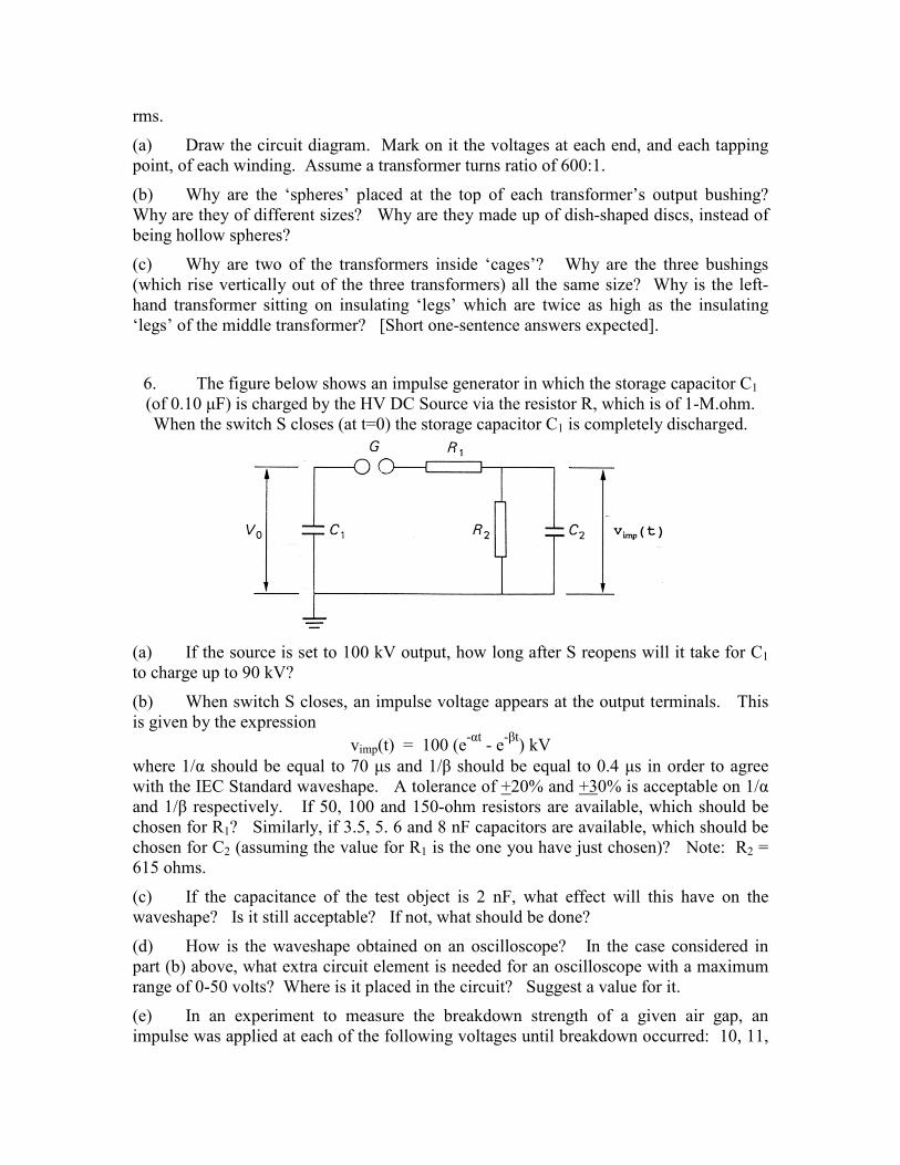
6. The figure below shows an impulse generator in which the storage capacitor C1
(of 0.10 µF) is charged by the HV DC Source via the resistor R, which is of 1-M.ohm.
When the switch S closes (at t=0) the storage capacitor C1 is completely discharged.
(a) If the source is set to 100 kV output, how long after S reopens will it take for C1
to charge up to 90 kV?
(b) When switch S closes, an impulse voltage appears at the output terminals. This
is given by the expression
vimp(t) = 100 (e-αt
- e-βt
) kV
where 1/α should be equal to 70 µs and 1/β should be equal to 0.4 µs in order to agree
with the IEC Standard waveshape. A tolerance of +20% and +30% is acceptable on 1/α
and 1/β respectively. If 50, 100 and 150-ohm resistors are available, which should be
chosen for R1? Similarly, if 3.5, 5. 6 and 8 nF capacitors are available, which should be
chosen for C2 (assuming the value for R1 is the one you have just chosen)? Note: R2 =
615 ohms.
(c) If the capacitance of the test object is 2 nF, what effect will this have on the
waveshape? Is it still acceptable? If not, what should be done?
(d) How is the waveshape obtained on an oscilloscope? In the case considered in
part (b) above, what extra circuit element is needed for an oscilloscope with a maximum
range of 0-50 volts? Where is it placed in the circuit? Suggest a value for it.
(e) In an experiment to measure the breakdown strength of a given air gap, an
impulse was applied at each of the following voltages until breakdown occurred: 10, 11,
12 … kV(peak). This was repeated several times to obtain the average impulse
breakdown voltage. Similarly a DC voltage was applied at each of the following
voltages until breakdown occurred: 10, 11, 12 … kV dc. This was repeated several
times to obtain the average DC breakdown voltage. The impulse breakdown voltage was
found to be about 1 kV higher than the DC breakdown voltage. Explain the reason for
the difference. (Note: the numbers are unimportant and no calculation is required.
About half a page of explanation is required).
7(a) Draw out the circuit of a single-stage impulse generator, comprising the following
units:
• a 0-220V autotransformer (e.g. `variac') supplied from the mains supply
• a 220V/50kV step-up transformer;
• a ‘voltage doubler’ dc source;
• a high-voltage switch; and
• an impulse-shaping circuit consisting of two resistors and two capacitors.
(b) Explain how the voltage doubler works and state the theoretical output voltage for
50 kV ac input. Why will the output voltage be slightly less than this?
7(a) Explain how the impulse generator works and hence write down approximate
formulae for the characteristic times of the impulse's rise and fall, in terms of the values
of the two resistors and two capacitors.
(b) Given that
• the characteristic times of the two exponentials forming a ‘1/50µs’ impulse are 0.4 µs
and 70 µs;
• the reservoir capacitor, C1 , is 0.1µF; and
• the ratio of the two resistors is 1:4
calculate the capacitance of the other capacitor, C2 , and the resistance of the two resistors