Highly Transparent and Toughened Poly(methyl methacrylate)Nanocomposite Films Containing Networks of Cellulose NanofibrilsHong Dong,*,†,‡,§ Yelena R. Sliozberg,†,‡ James F. Snyder,† Joshua Steele,† Tanya L. Chantawansri,†
Joshua A. Orlicki,† Scott D. Walck,†,‡ Richard S. Reiner,∥ and Alan W. Rudie∥
†Macromolecular Science & Technology Branch, U.S. Army Research Laboratory, Aberdeen Proving Ground, Maryland 21005,United States‡TKC Global Solutions, LLC, Aberdeen, Maryland 21005, United States∥Forest Products Laboratory, USDA Forest Service, Madison, Wisconsin 53726, United States
*S Supporting Information
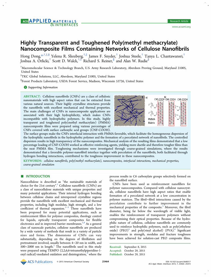
ABSTRACT: Cellulose nanofibrils (CNFs) are a class of cellulosicnanomaterials with high aspect ratios that can be extracted fromvarious natural sources. Their highly crystalline structures providethe nanofibrils with excellent mechanical and thermal properties.The main challenges of CNFs in nanocomposite applications areassociated with their high hydrophilicity, which makes CNFsincompatible with hydrophobic polymers. In this study, highlytransparent and toughened poly(methyl methacrylate) (PMMA)nanocomposite films were prepared using various percentages ofCNFs covered with surface carboxylic acid groups (CNF-COOH).The surface groups make the CNFs interfacial interaction with PMMA favorable, which facilitate the homogeneous dispersion ofthe hydrophilic nanofibrils in the hydrophobic polymer and the formation of a percolated network of nanofibrils. The controlleddispersion results in high transparency of the nanocomposites. Mechanical analysis of the resulting films demonstrated that a lowpercentage loading of CNF-COOH worked as effective reinforcing agents, yielding more ductile and therefore tougher films thanthe neat PMMA film. Toughening mechanisms were investigated through coarse-grained simulations, where the resultsdemonstrated that a favorable polymer-nanofibril interface together with percolation of the nanofibrils, both facilitated throughhydrogen bonding interactions, contributed to the toughness improvement in these nanocomposites.
Nanocellulose is described as “the sustainable materials ofchoice for the 21st century”.1 Cellulose nanofibrils (CNFs) area class of nanocellulose materials with unique properties andmany potential applications. Their internal hydrogen bondingbetween cellulose chains and interspersed crystalline regionsprovide the nanofibrils with excellent mechanical and thermalproperties, including high modulus, high strength, and a lowcoefficient of thermal expansion.1−3 These nanofibrils havebeen proposed for many potential applications, such asreinforcement fillers for polymer composites, rheology controlfor liquids, optically transparent composites for flexibleelectronics and in improved barrier membranes.1,4 As a generalclass of nanoscale particles, cellulose nanofibrils are producedby a wide variety of methods that result in a variety of particlesizes and forms. The dimensions of CNFs can varysubstantially, depending on the degrees of fibrillation andpretreatment involved, usually between 4−20 nm in width, and500−2000 nm in length.2 The nanofibrils used in this studywere prepared using TEMPO (2,2,6,6-tetramethylpiperidine-1-oxyl radical)-mediated oxidation and disintegration,3 where the
process results in C6 carboxylate groups selectively formed onthe nanofibril surface.CNFs have been used as reinforcement nanofillers for
polymer nanocomposites. Compared with cellulose nanocryst-als, cellulose nanofibrils have high aspect ratios that enableformation of a percolated network at a low concentration inpolymer matrices. The fibril−fibril interactions caused by thepercolation contribute to further improvement in themechanical properties of the composite.5 Moreover, the fibrildiameter, being far below the wavelength of visible light,enables the reinforcement of transparent polymers withoutcompromising their optical properties. Because of the hydro-philic nature of cellulose, cellulose nanofibrils are commonlyused to reinforce hydrophilic polymers, such as poly(ethyleneoxide) (PEO)5 and poly(vinyl alcohol) (PVA).6 Significantimprovements in strength, modulus and fracture toughnesshave been achieved for solution-cast PEO composite films.
Received: September 8, 2015Accepted: October 29, 2015Published: October 29, 2015
These increases were attributed to CNFs high mechanicalproperties, good dispersion and strong interfacial hydrogenbonding between cellulose and the matrix.5
Even so, the main challenges of utilizing CNFs in compositeapplications are associated with the high hydrophilicity, whichmakes them incompatible with hydrophobic polymers. Thehydrophilic nature, along with their inherent tendency to formaggregates held together by hydrogen bonding, impedesdispersing CNFs in hydrophobic polymers and thereforeleads to lower mechanical properties of the composites thanpredicted. To address this deficiency, researchers investigatedsurface modifications based on polymer grafting, couplingagents, acetylation, and cationic modification to improvecompatibility and dispersion in polymer matrices.4,7 As anexample, cellulose nanocrystals and microfibrils were chemicallymodified with N-octadecyl isocyanate, where the chemicalgrafting was found to improve compatibility with polycapro-lactone and dispersity.8 Polystyrene containing various ratios ofdispersed TEMPO-oxidized cellulose nanofibrils exhibitedincreases in tensile strength and elastic modulus. Thereinforcement effects were observed even at low addition levelsin relation to the neat film.9 In many studies, improvements tothe modulus of hydrophobic polymers through reinforcementwith cellulose nanofibrils was coupled with a reduction intoughness due to reduced elongation at break. This increasedbrittleness may be associated with nanofibril aggregation inhydrophobic polymers or weak hydrophilic nanofiller−hydro-phobic matrix interfaces. Because effective utilization ofnanofillers in composite applications depends strongly ontheir ability to be dispersed homogeneously within a polymermatrix as well as interfacial interactions,10,11 an optimizedinterfacial interaction between CNFs and hydrophobic polymermatrix and good dispersion of CNFs should lead to efficientload transfer to the hard component of the composite and/orallow for significant energy dissipation without macroscopicfailure, resulting in enhanced mechanical properties of thematerials.Poly(methyl methacrylate) (PMMA) is a commonly
employed glassy thermoplastic polymer. Because of excellenttransparency in the visible spectrum, PMMA is widely used inoptical applications, especially as a matrix for nonlinear opticalmaterials. However, applicability is limited by relatively highbrittleness. Incorporation of reinforcing fillers, such as CNFs,into a PMMA matrix could result in an enhanced material.Previously reported work includes composites prepared bysolution blending of PMMA and PMMA-grafted CNFsfollowed by injection and compression molding. The tensiletesting showed no improvement of the mechanical propertiesand the transparency of the composites was notably decreased,because of the visible heterogeneity of the composites causedby insufficient mixing of the components.12
This study focuses on incorporating TEMPO-oxidized CNFsinto PMMA as an approach to improve toughness whilemaintaining optical transparency. In this work, low percentagesof modified CNFs, where carboxylate groups on the nanofibrilswere protonated to carboxylic acid groups, were mixed in aPMMA matrix. The effect of incorporating CNFs into PMMAwas studied by microscopy, thermal analysis, and mechanicaltesting. This, together with modeling the mechanism formaterial failure, provides further insight on CNF reinforcedhydrophobic polymers. Computational models at the coarse-grained level were used to understand the fundamentalmechanism responsible for toughening of these materials.
Computed results are shown to have good qualitativeagreement with experimental data obtained for the PMMAnanocomposite films containing low percentages of carboxylCNFs.
■ EXPERIMENTAL SECTIONMaterials. Aqueous dispersion of carboxylated cellulose nanofibrils
(balanced with sodium ions, noted as CNF-COONa) nanofibrils wereproduced from wood pulp using the TEMPO oxidation technique andsodium hypochlorite as the stochiometric oxidant.13 The waterdispersion of CNFs used in this study has a concentration of 1.0 wt% and a surface carboxylate content of 1.3 mmol/g. Poly(methylmethacrylate) (PMMA), N,N-dimethylformamide (DMF), and allother chemicals were of analytical grade and used as received.Deionized water with resistance ∼18.2 MΩ m was used in allexperiments.
Preparation of CNF-COOH/PMMA Film. The “as-produced”TEMPO-oxidized CNFs carry surface sodium carboxylate groups,which is described as CNF-COONa in this report. CNF-COONa wasprotonated to CNF-COOH using a method adapted from Isogai’sgroup.14 Briefly, 1.0 wt % CNF-COONa was diluted to 0.1 wt % inH2O, which was adjusted to pH ∼2 with 1 N HCl. Gel particles ofCNF-COOH were obtained by centrifuging to remove water from themixture. The gel particles were then washed and centrifugedrepeatedly with H2O several times. The CNF-COOH in H2O particleswas completely solvent-exchanged to acetone by repeatedly addingacetone and centrifuging to remove solvent. DMF was then added tothe CNF-COOH particles in acetone. The mixture was evaporatedusing a rotary evaporator under vacuum and at 50 °C to removeacetone. The concentration of suspended CNF-COOH/DMFparticles was determined by dry weight. Clear dispersion of CNF-COOH in DMF was obtained by diluting the concentrated CNF-COOH/DMF with DMF and sonicating in a water-bath sonicator(Fisher Scientific, FS30H) for 30 min to 1 h. The dispersion aftersonication was examined using a cross polarizer. The presence of flowbirefringence and absence of gel particles were used to indicate gooddispersion. The dispersion was further examined using transmissionelectron microscopy as described below.
To prepare the nanocomposite films, 5 g of PMMA dissolved inDMF was mixed with CNF-COOH/DMF dispersion and stirred for atleast 1 h. The weight ratio of CNF-COOH in the PMMA/CNF-COOH was varied from 0 to 5 wt %. The solution of CNF-COOH/PMMA in DMF was cast in a glass crystallizing dish. The solution wasdried in an oven purged with nitrogen gas at a temperature below 40°C. The PMMA/CNF-COOH nanocomposite films thus formed weredetached from glass dishes and vacuum-dried at 50 °C for several days.The resulting PMMA/CNF-COOH nanocomposite films were ∼0.2mm in thickness.
Characterizations. Electron Microscopy. The dispersions ofnanofibrils in solvents were characterized using a JEOL 2100Ftransmission electron microscope (TEM) operated at 200 kV. For theTEM samples of the CNF dispersion in H2O or the CNF-COOHdispersion in DMF, the TEM grid covered with an ultrathin carbonfilm was treated with air plasma for 45 s to increase hydrophilicity ofthe carbon support film and thus prevent aggregation of the nanofibrilsdried on the grid. A droplet of the diluted nanofibril dispersion wascast on the grid and remained on the grid for 1 min. Then the extrafluid was removed with the edge of filter paper, and the remainingnanofibrils were stained with 2% aqueous solution of uranyl acetatebefore being air-dried in order to enhance the TEM image contrast.To examine the dispersion of CNF-COOH in the nanocomposite film,we embedded the film in EPO-FIX embedding epoxy resin (ElectronMicroscopy Sciences) and cured overnight at room temperature. Theembedded film was then cross-sectioned using a Leica microtome. Thesliced thin sections with thickness ∼100 nm were collected on theTEM grids and stained with 2% uranyl acetate. The dispersion ofnanofibrils in the nanocomposte films was investigated using the JEOL2100F scope with scanning transition electron microscopy (STEM)mode. Bright-field (BF) STEM images were acquired using a JEOL BF
ACS Applied Materials & Interfaces Research Article
detector. High-angle annular dark-field (HAADF) images wereacquired with a Gatan 806 HAADF detector. The fracture surfacesof the tensile samples were characterized using a Hitachi S-4700 field-emission scanning electron microscope (FESEM) at an acceleratingvoltage of 5 kV. The samples were sputter-coated with Au/Pt alloy toreduce charging before FESEM operation.Thermal Analysis. Differential scanning calorimetry (DSC) was
performed using a TA DSC Q1000 instrument. The tests were carriedout at a ramping rate of 10 °C/min from room temperature to 200 °Cunder a nitrogen atmosphere.UV−Vis Spectroscopy. UV−vis spectra of the films were collected
at a wavelength range of 250 to 900 nm using a Beckman Coulter DU800 spectrophotometer. The transmission spectra were acquired onthe free-standing films using air as blank.Dynamic Mechanical Analysis. Dynamic mechanical analysis
(DMA) of the composite films was conducted using a DMA Q800(TA Instruments) equipped with a film tension clamp. Tests were runfrom −20 to 120 °C at a rate of 3 °C/min. Oscillation amplitude of 5μm (within linear range) was applied on all samples. At least threerepeats were tested for each sample.Tensile Testing. Uniaxial tensile loading was performed on flat,
dogbone test specimens based on the dimensions in ASTM D638.Test specimens were laser-cut into dog-bone geometries from the castthin films. An Instron model 1122 load frame with a 50 N load cell wasused to carry out the tests. The specimens were loaded in tension at across-head speed of 12 mm/min. The load and displacement valueswere recorded and the strain was calculated using digital imagecorrelation.
■ COMPUTATIONAL MODEL AND METHODSSupplementary to experimental efforts, computational modelingprovides a powerful means to investigate a broad range of parametersthat are challenging to explore experimentally. The complexity and sizeof these nanocomposite structures restrict the use of all-atomcomputer simulations. Instead a coarse-grained (CG) representationis utilized to extend the length and time scale accessible to simulation,where atoms are grouped together to form effective interaction sites.The resolution accessible to this simulation method is adequatebecause the modeling will only be used to elucidate the fundamentalmechanism responsible for toughening in PMMA compositescontaining cellulose nanofibrils. These simulations were performedusing the large-scale atomic/molecular massively parallel simulator(LAMMPS).15,16
Coarse-grained molecular dynamics simulations of the neat orcomposite polymer system were performed using the standard genericbead−spring model,17 which has been shown to be an excellenttechnique to study the structural, dynamical, and mechanicalproperties of large variety of polymer systems.18−21 The simulationbox for our pure polymer system is composed of 8000 linear flexiblechains, where each chain contains Np = 30 beads. To model the CNF-COOH dispersion in the composite system, we added 50 rigid longrods each composed of Nr = 50 beads.All beads have a mass m and the pair interaction between
topologically nonconnected beads is described by the standardtruncated Lennard−-Jones (LJ) pair potential
= − − +⎜ ⎟ ⎜ ⎟⎡⎣⎢⎢⎛⎝
⎞⎠
⎛⎝
⎞⎠
⎛⎝⎜
⎞⎠⎟
⎛⎝⎜
⎞⎠⎟
⎤⎦⎥⎥U r u
ar
ar
ar
ar
( ) 4LJ 0
12 6
c
12
c
6
(1)
where u0 is the depth of the potential well and a represents a size of abead. We express all quantities in terms of the mass m, intermonomerbinding energy u0, monomer diameter a and characteristic time τ =(ma2/u0)
1/2, where we use the standard LJ potential cutoff, rc = 2.5a.Topologically bound monomers interact according to the standard
FENE/Lennard−Jones bonded potential, UFENE/LJ
= +U r U r U r( ) ( ) ( )FENE/LJ FENE WCA (2)
and
= − −⎡⎣⎢⎢
⎛⎝⎜
⎞⎠⎟
⎤⎦⎥⎥U r
aR
rR
( )2
ln 1FENEFENE
02
0
2
(3)
where UFENE is the finite extensible nonlinear elastic potential (FENE).The standard parameter values of the spring constant, aFENE = 30u0/a
2
and the maximum extension, R0 = 1.5a, were employed. The so-calledWeeks−Chandler−Andersen excluded volume potential, UWCA, isobtained by setting rc = 21/6a in eq 1.
The rigidity of the long rods is controlled through a harmonicangular potential
θ θ θ= −U k( ) ( )a 02 (4)
where θ is the angle between triplets of connected beads, θ0 = π is theequilibrium value of the angle, and k = 300u0/rad
2.These initial systems were built and first equilibrated by using a fast
equilibration protocol.22 Periodic boundary conditions are applied inall three directions of the initially cubic simulation cells, using a MDtime step of Δt = 0.01 τ. Temperature, T = 1.0u0/kBT, is controlledduring the entire simulation by a Langevin thermostat with a dampingtime of 1.0 τ. Initially, the pair interaction between nonbondedparticles is described by the excluded volume potential, UWCA. Thehydrogen bonding interactions between CNF and polymer matrix aresimulated by allowing the polymer chains and the long rods to createFENE bonds, if the distance between attractive sites of polymer chainsand rods is less than 1.2a. In the polymer chain and rod, we utilized 3and 25 evenly distributed attractive sites, respectively, where attractiveLJ interactions (rc = 2.5a) are used between these sites before reaction.The simulation was allowed to run until all of the polymer chainsattractive sites have reacted with those on the rods.
After this step, the LJ potential cutoff, rc is changed from 21/6a to2.5a for all monomers. The systems were then quenched from T =1.0u0/kBT to T = 0.3u0/kBT at constant volume over a time interval of1 × 105 τ to reach a glassy state. The glass transition temperature Tgfor the Lennard−Jones polymer23 is Tg = 0.5u0/kBT. Finally, thesystems were equilibrated at zero hydrostatic pressure, yielding anequilibrium monomer number density ρ = 0.87a−3.
After equilibration, simulations of uniaxial-stress tensile deformationin the z direction were performed. The brittleness of PMMA is knownto be the result of catastrophic strain localization in the form of crazes,which results in failure prior to the yield point. To simulate crazeformation, Lz length is increased at constant engineering strain rate ε̇ =1 × 10⁻⁴ τ-1, whereas the other dimensions of the cell are held fixed.19
For the deformation simulations, the time step is reduced to 0.075τ.Although the employed strain and cooling rates are much higher thantypical experimental rates because of limitations in accessible strainrates and equilibration of the initial structure, the stress generally hasweak (logarithmic) rate dependence in polymer glasses.18
During the deformation process, bonds intrinsic to the polymer orthe rods are set to break when the distance between a pair of bondedparticles is greater than 1.4a, whereas bonds formed between the rodsand polymer matrix were allowed to break at shorter distance of 1.3a.In our simulations, broken bonds are not allowed to reform. For thecomposite systems, the deformation simulations were stopped oncethe rods started to break.
■ RESULTS AND DISCUSSIONDispersion and Nanocomposite Film Preparation.
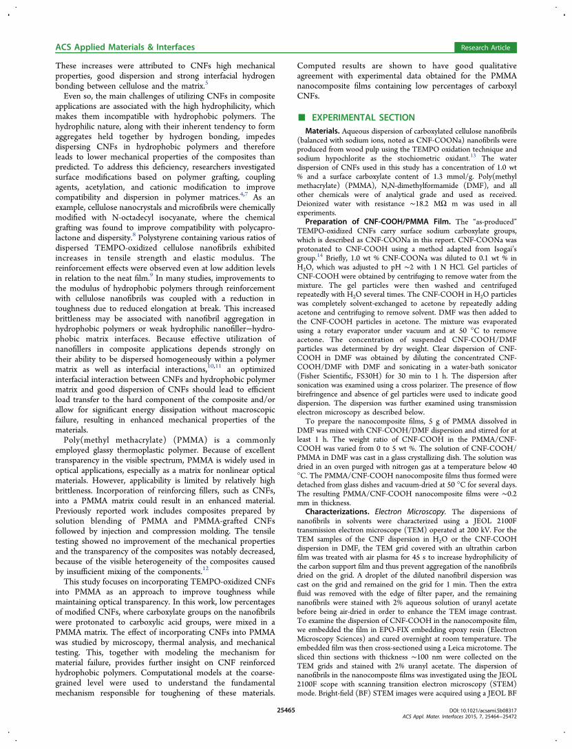
Figure 1 shows a TEM image of “as-produced” cellulosenanofibrils that were used in this study. The nanofibrils have anaverage diameter of ∼4 nm determined by taking measure-ments from several TEM images. The nanofibrils carrycarboxylate groups balanced with sodium ions (CNF-COONa), which provides repulsive charges that aid in thedispersion of nanofibrils in H2O. However, direct dispersion ofCNF-COONa by solvent exchange in many common organicsolvents is very limited. Upon addition of common organicsolvents, gel particles of CNF-COONa form immediately and
ACS Applied Materials & Interfaces Research Article
cannot be redispersed by sonication. Okita et al.14 investigatedthe dispersibility of CNF-COONa and CNF-COOH in variousorganic solvents. By converting the surface carboxylate groupsof CNF-COONa to carboxylic acid groups, the nanofibrils werefound to individually disperse in polar aprotic organic solventssuch as N,N-dimethylacetamide (DMAc) and DMF at a lowconcentration.14 The conversion of the surface carboxylate tocarboxylic acid and subsequent dispersion in nonaqueous mediacan also expand the range of surface chemistry to be performedon the nanofibrils or enable surface interactions with thepolymer matrix.The dispersion of CNF-COOH gel particles in DMF after
bath sonication was visually examined using a cross-polarizer,where the absence of visible gel particles and presence of flowbirefringence indicate good dispersion of the nanofibrils in thesolvent. The sonication process seems to be an efficient way ofbreaking the weak hydrogen bonds and dispersing nanofibrils inpolar organic solvents. However, a recent study showed thatintensive high-energy sonication had a major impact on thechain bonding within the cellulose supramolecular structure.24
In this study, low-energy bath sonication was applied todisperse weakly bonded CNF-COOH gel particles into DMF.To compare the dimension of the redispersed nanofibrils(CNF-COOH) with “as-produced” CNF-COONa nanofibrils,we examined the morphology of dispersed CNF-COOH inDMF under TEM. As shown in Figure 1b, the nanofibrils ofCNF-COOH maintain the fibril structure. The averagediameter measured from Figure 1b and other TEM imageswere ∼4 nm with average length ∼440 nm, similar to those of“as-produced” nanofibrils.PMMA films with different weight ratios of CNF-COOH
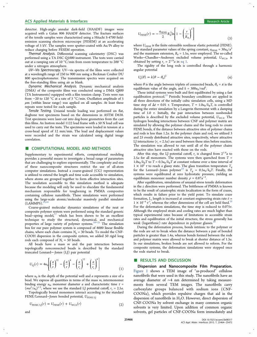
and neat PMMA film were prepared. Visually, the nano-composite films have high transparency, comparable to the neatPMMA film, as shown in Figure 2a. The surfaces of theprepared films are very smooth. Further evaluation of thetransparency of the PMMA nanocomposite films wasperformed using UV−vis transmittance. Figure 2b shows thatthe PMMA/CNF-COOH film containing 0.5 wt % up to 3 wt% of nanofibrils have similar transmittance as that of the neatPMMA film in the range of visible wavelengths. Thetransmittances at 550 nm were used as relative values tocompare the composite films with the neat film. The neatPMMA film displays a transmittance of 92% at 550 nm. PMMAfilms containing 1 wt % nanofibrils or 3 wt % nanofibrils havesame level of light transmittance as that of neat film with bothalso having a transmittance of 92% at 550 nm. When thecontent of nanofibrils in PMMA increases to 5 wt %, the lighttransmittance at 550 nm slightly decreases to 90%. Toward theblue side of the spectrum, such as 450 nm, the transmittance of
5 wt % further decreases compared with other contents. Thisindicates some aggregation of nanofibrils in PMMA matrix.The dispersion of 3 wt % CNF-COOH in PMMA film was
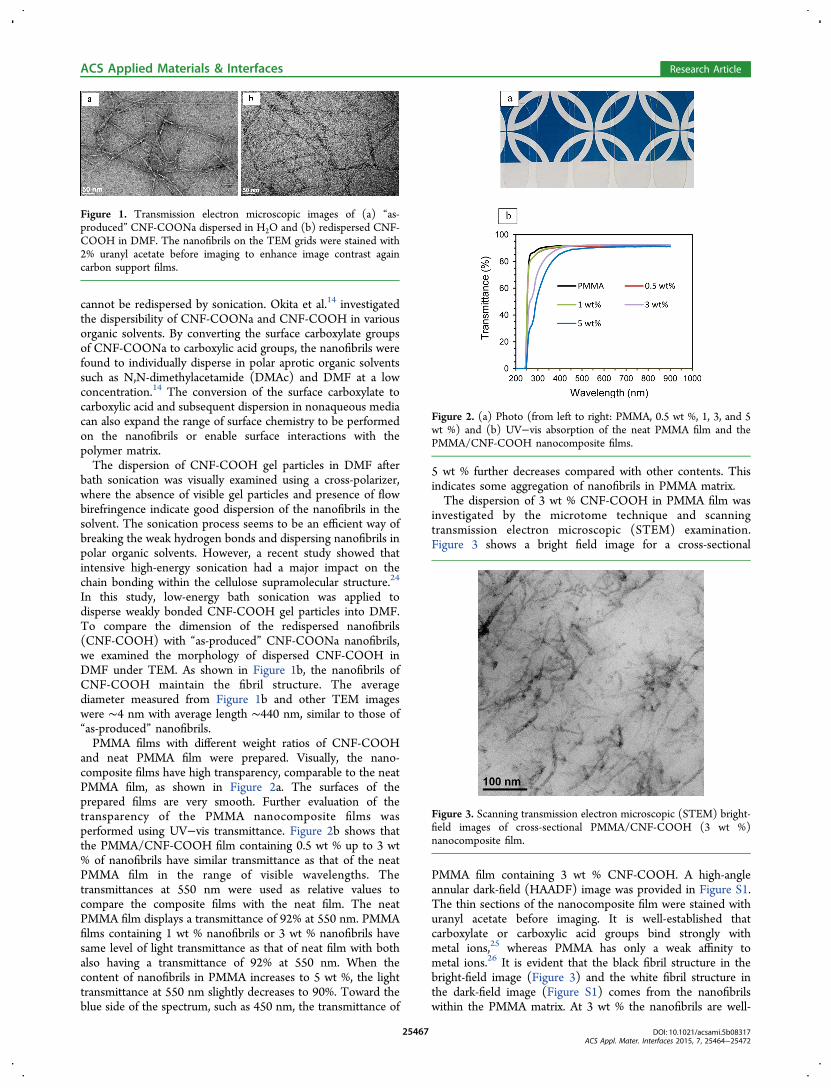
investigated by the microtome technique and scanningtransmission electron microscopic (STEM) examination.Figure 3 shows a bright field image for a cross-sectional
PMMA film containing 3 wt % CNF-COOH. A high-angleannular dark-field (HAADF) image was provided in Figure S1.The thin sections of the nanocomposite film were stained withuranyl acetate before imaging. It is well-established thatcarboxylate or carboxylic acid groups bind strongly withmetal ions,25 whereas PMMA has only a weak affinity tometal ions.26 It is evident that the black fibril structure in thebright-field image (Figure 3) and the white fibril structure inthe dark-field image (Figure S1) comes from the nanofibrilswithin the PMMA matrix. At 3 wt % the nanofibrils are well-
Figure 1. Transmission electron microscopic images of (a) “as-produced” CNF-COONa dispersed in H2O and (b) redispersed CNF-COOH in DMF. The nanofibrils on the TEM grids were stained with2% uranyl acetate before imaging to enhance image contrast againcarbon support films.
Figure 2. (a) Photo (from left to right: PMMA, 0.5 wt %, 1, 3, and 5wt %) and (b) UV−vis absorption of the neat PMMA film and thePMMA/CNF-COOH nanocomposite films.
Figure 3. Scanning transmission electron microscopic (STEM) bright-field images of cross-sectional PMMA/CNF-COOH (3 wt %)nanocomposite film.
ACS Applied Materials & Interfaces Research Article
dispersed to form an interconnected long-range networkstructure in the PMMA matrix with little aggregation. Sampleswith lower CNF contents should have a similar level ofdispersion because of similar level of film transparency at visiblerange. At 5% CNF content, the CNFs are expected to be well-dispersed, but a small portion of the CNFs are aggregated onthe basis of UV−vis results.Thermal Property and Interactions. Dynamic thermal
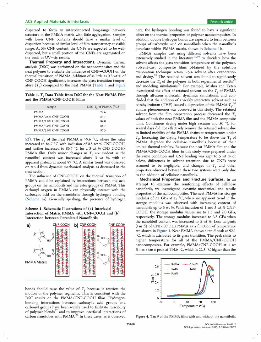
analysis (DSC) was performed on the nanocomposites and theneat polymer to evaluate the influence of CNF−COOH on thethermal transition of PMMA. Addition of as little as 0.5 wt % ofCNF-COOH significantly increases the glass transition temper-ature (Tg) compared to the neat PMMA (Table 1 and Figure
S2). The Tg of the neat PMMA is 79.6 °C, where the valueincreased to 84.7 °C with inclusion of 0.5 wt % CNF-COOH,and further increased to 86.7 °C for a 3 wt % CNF-COOH/PMMA film. Only minor changes in Tg are evident as thenanofibril content was increased above 3 wt %, with anapparent plateau at about 87 °C. A similar trend was observedon tan δ from dynamic mechanical analysis as discussed in thenext section.The influence of CNF-COOH on the thermal transition of
PMMA could be explained by interactions between the acidgroups on the nanofibrils and the ester groups of PMMA. Thiscarbonyl oxygen in PMMA can physically interact with thecarboxylic acid on the nanofibrils through hydrogen bonding(Scheme 1a). Generally speaking, the presence of hydrogen
bonds should raise the value of Tg because it restricts themotion of the polymer segments. This is consistent with theDSC results on the PMMA/CNF-COOH films. Hydrogen-bonding interactions between carboxylic acid groups andcarbonyl groups have been widely used to facilitate miscibilityof polymer blends27 and to improve interfacial interactions ofcarbon nanotubes with PMMA.28 In these cases, as is observed
here, the hydrogen bonding was found to have a significanteffect on the thermal properties of polymer nanocomposites. Inaddition, double hydrogen bonds are expected to form betweengroups of carboxylic acid on nanofibrils when the nanofibrilspercolate within PMMA matrix, shown in Scheme 1b.PMMA samples cast using different solvents have been
extensively studied in the literature29,30 to elucidate how thesolvent affects the glass transition temperature of the polymer.Solvent-cast composite films obtained by the solutionevaporation technique retain ∼5% solvent after evaporationand drying.29 The retained solvent was found to significantlydecrease the Tg of the polymer in both experimental results29
and modeling simulations.30 For example, Mishra and Keteninvestigated the effect of retained solvent on the Tg of PMMAthrough all-atom molecular dynamics simulations, and con-cluded that the addition of a weakly interactive solvent such astetrahydrofuran (THF) caused a depression of the PMMA Tg.
30
Similar phenomenon was observed in this study. The retainedsolvent from the film preparation process decreased the Tgvalues of both the neat PMMA film and the PMMA compositefilms. Continuous drying under high vacuum and 50 °C forseveral days did not effectively remove the retained solvent dueto limited mobility of the PMMA chains at temperatures underTg. Increasing the drying temperature to be above the Tg ofPMMA degrades the cellulose nanofibrils because of theirlimited thermal stability. Because the neat PMMA film and thePMMA/CNF-COOH films in this study were prepared underthe same condition and CNF loading was kept to 5 wt % orbelow, differences in solvent retention due to CNFs wereassumed to be negligible, and changes in Tg and otherproperties observed between these two systems were only dueto the addition of cellulose nanofibrils.
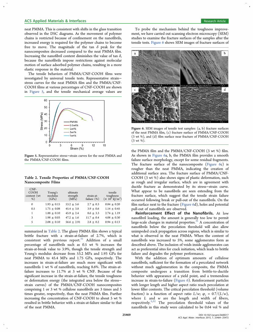
Mechanical Properties and Fracture Surfaces. In anattempt to examine the reinforcing effects of cellulosenanofibrils, we investigated dynamic mechanical and tensileproperties of the nanocomposites. The neat PMMA has storagemodulus of 2.1 GPa at 25 °C, where no apparent trend in thestorage modulus was observed with increasing content ofnanofibrils up to 5 wt %. With inclusion of 1 and 3 wt % CNF-COOH, the storage modulus values are to 1.5 and 2.0 GPa,respectively. The storage modulus increased to 3.5 GPa whenthe nanofibril content was increased to 5 wt %. Loss tangents(tan δ) of CNF-COOH/PMMA as a function of temperatureare shown in Figure 4. Neat PMMA shows a tan δ peak at 92.1°C, which is attributed to its glass transition. The peak shifts tohigher temperature for all of the PMMA/CNF-COOHnanocomposites. For example, PMMA/CNF-COOH at 1 wt% has a tan δ peak at 114.6 °C, which is 22.5 °C higher than the
Table 1. Tg Data Table from DSC for the Neat PMMA Filmand the PMMA/CNF-COOH Films
neat PMMA. This is consistent with shifts in the glass transitionobserved in the DSC diagrams. As the movement of polymerchains is restricted because of confinement on the nanofibrils,increased energy is required for the polymer chains to becomefree to move. The magnitude of the tan δ peak for thenanocomposites decreased compared to the neat PMMA film.Increasing the nanofibril content diminishes the value of tan δ,because the nanofibrils impose restrictions against molecularmotion of surface adsorbed polymer chains, resulting in a moreelastic response in the material.The tensile behaviors of PMMA/CNF-COOH films were
investigated by universal tensile tests. Representative strain−stress curves for the neat PMMA film and the PMMA/CNF-COOH films at various percentages of CNF-COOH are shownin Figure 5, and the tensile mechanical average values are
summarized in Table 2. The glassy PMMA film shows a typicalbrittle fracture with a strain-at-failure of 2.7%, which isconsistent with previous report.31 Addition of a smallpercentage of nanofibrils such as 0.5 wt % increases thestrain-at-break value to 3.9%, though the tensile strength andYoung’s modulus decrease from 53.2 MPa and 1.93 GPa forneat PMMA to 45.4 MPa and 1.75 GPa, respectively. Theincreases in strain-at-failure are much more significant withnanofibrils 1 wt % of nanofibrils, reaching 8.6%. The strain-at-failure increases to 11.7% at 3 wt % CNF. Because of thesignificant increase in the strain-at-failure, the tensile toughnessor deformation energy (the integrated area below the stress−strain curves) of the PMMA/CNF-COOH nanocompositescomprising 1 or 3 wt % cellulose nanofibrils are 3 times and 5times greater, respectively, than the neat PMMA film. Furtherincreasing the concentration of CNF-COOH to about 5 wt %resulted in brittle behavior with a strain-at-failure similar to thatof the neat PMMA.
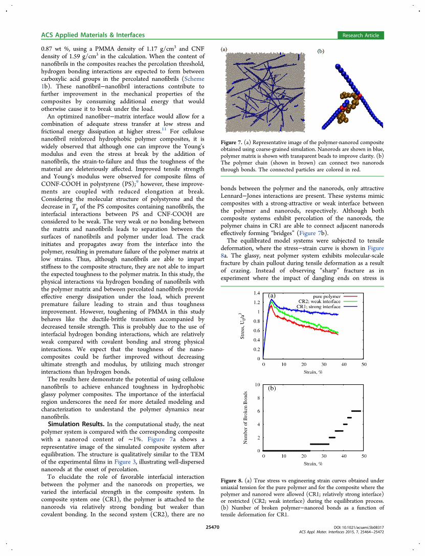
To probe the mechanism behind the toughness improve-ment, we have carried out scanning electron microscopy (SEM)studies to examine the fracture surfaces of the samples after thetensile tests. Figure 6 shows SEM images of fracture surfaces of
the PMMA film and the PMMA/CNF-COOH (3 wt %) film.As shown in Figure 6a, b, the PMMA film provides a smoothfailure surface morphology, except for some residual fragments.The fracture surface of the nanocomposite (Figure 6c) isrougher than the neat PMMA, indicating the creation ofadditional surface area. The fracture surface of PMMA/CNF-COOH (3 wt %) also shows signs of plastic deformation, suchas rough and irregular surface, which are in agreement withductile fracture as demonstrated by its stress−strain curve.What appear to be nanofibrils are seen extending from thefracture surface, which suggest that the tensile strain failureoccurred following break or pull-out of the nanofibrils. On thefilm surface next to the fracture (Figure 6d), holes and potentialpull-out of nanofibrils are observed.
Reinforcement Effect of the Nanofibrils. At lownanofibril loading, the amount is generally too low to permitlarge-scale changes in material properties.31 A concentration ofnanofibrils below the percolation threshold will also allowunimpeded crack propagation across regions, which is similar towhat is observed in the neat PMMA. When the content ofnanofibrils was increased to 5%, some agglomerates form asdescribed above. The inclusion of voids inside agglomerates canact as preferential sites for crack initiation, which leads to brittlefailure and degrades the polymer performance.With the addition of optimum amounts of cellulose
nanofibrils, sufficient for the formation of a percolated networkwithout much agglomeration in the composite, the PMMAcomposite undergoes a transition from brittle-to-ductilebehavior with appearance of a yield point, and a tremendousincrease in strain-to-failure (Figure 6). Reinforcement particleswith longer length and higher aspect ratio reach percolation atlower filler contents. The critical percolation threshold (volumefraction) is a function of aspect ratio L/w; φc = 0.7/(L/w),where L and w are the length and width of fibers,respectively.5,32 The percolation threshold values of thenanofibrils in this study were calculated to be 0.64 vol % and
Figure 5. Representative stress−strain curves for the neat PMMA andthe PMMA/CNF-COOH films.
Table 2. Tensile Properties of PMMA/CNF-COOHNanocomposite Films
Figure 6. SEM images of tensile test samples: (a, b) fracture surfacesof the neat PMMA film, (c) fracture surface of PMMA/CNF-COOH(3 wt %), and (d) film surface near fracture of PMMA/CNF-COOH(3 wt %).
ACS Applied Materials & Interfaces Research Article
0.87 wt %, using a PMMA density of 1.17 g/cm3 and CNFdensity of 1.59 g/cm3 in the calculation. When the content ofnanofibrils in the composites reaches the percolation threshold,hydrogen bonding interactions are expected to form betweencarboxylic acid groups in the percolated nanofibrils (Scheme1b). These nanofibril−nanofibril interactions contribute tofurther improvement in the mechanical properties of thecomposites by consuming additional energy that wouldotherwise cause it to break under the load.An optimized nanofiber−matrix interface would allow for a
combination of adequate stress transfer at low stress andfrictional energy dissipation at higher stress.11 For cellulosenanofibril reinforced hydrophobic polymer composites, it iswidely observed that although one can improve the Young’smodulus and even the stress at break by the addition ofnanofibrils, the strain-to-failure and thus the toughness of thematerial are deleteriously affected. Improved tensile strengthand Young’s modulus were observed for composite films ofCONF-COOH in polystyrene (PS);9 however, these improve-ments are coupled with reduced elongation at break.Considering the molecular structure of polystyrene and thedecrease in Tg of the PS composites containing nanofibrils, theinterfacial interactions between PS and CNF-COOH areconsidered to be weak. The very weak or no bonding betweenthe matrix and nanofibrils leads to separation between thesurfaces of nanofibrils and polymer under load. The crackinitiates and propagates away from the interface into thepolymer, resulting in premature failure of the polymer matrix atlow strains. Thus, although nanofibrils are able to impartstiffness to the composite structure, they are not able to impartthe expected toughness to the polymer matrix. In this study, thephysical interactions via hydrogen bonding of nanofibrils withthe polymer matrix and between percolated nanofibrils provideeffective energy dissipation under the load, which preventpremature failure leading to strain and thus toughnessimprovement. However, toughening of PMMA in this studybehaves like the ductile-brittle transition accompanied bydecreased tensile strength. This is probably due to the use ofinterfacial hydrogen bonding interactions, which are relativelyweak compared with covalent bonding and strong physicalinteractions. We expect that the toughness of the nano-composites could be further improved without decreasingultimate strength and modulus, by utilizing much strongerinteractions than hydrogen bonds.The results here demonstrate the potential of using cellulose
nanofibrils to achieve enhanced toughness in hydrophobicglassy polymer composites. The importance of the interfacialregion underscores the need for more detailed modeling andcharacterization to understand the polymer dynamics nearnanofibrils.Simulation Results. In the computational study, the neat
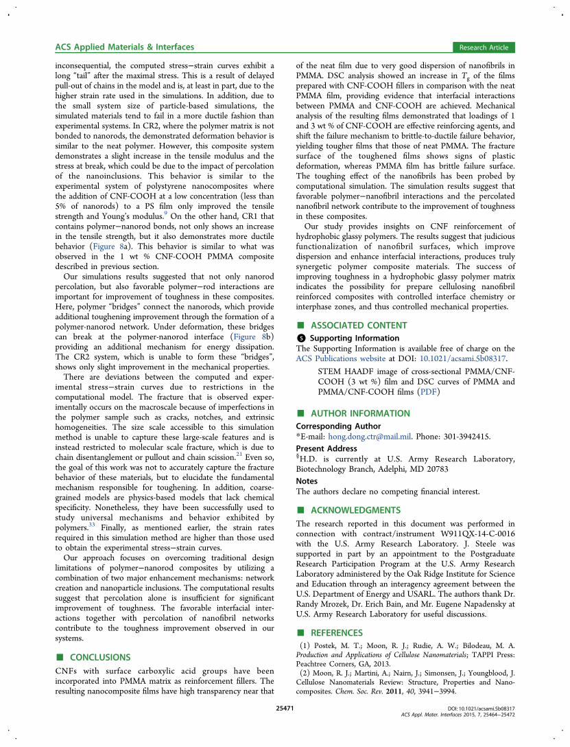
polymer system is compared with the corresponding compositewith a nanorod content of ∼1%. Figure 7a shows arepresentative image of the simulated composite system afterequilibration. The structure is qualitatively similar to the TEMof the experimental films in Figure 3, illustrating well-dispersednanorods at the onset of percolation.To elucidate the role of favorable interfacial interaction
between the polymer and the nanorods on properties, wevaried the interfacial strength in the composite system. Incomposite system one (CR1), the polymer is attached to thenanorods via relatively strong bonding but weaker thancovalent bonding. In the second system (CR2), there are no
bonds between the polymer and the nanorods, only attractiveLennard−Jones interactions are present. These systems mimiccomposites with a strong-attractive or weak interface betweenthe polymer and nanorods, respectively. Although bothcomposite systems exhibit percolation of the nanorods, thepolymer chains in CR1 are able to connect adjacent nanorodseffectively forming “bridges” (Figure 7b).The equilibrated model systems were subjected to tensile
deformation, where the stress−strain curve is shown in Figure8a. The glassy, neat polymer system exhibits molecular-scalefracture by chain pullout during tensile deformation as a resultof crazing. Instead of observing “sharp” fracture as inexperiment where the impact of dangling ends on stress is
Figure 7. (a) Representative image of the polymer-nanorod compositeobtained using coarse-grained simulation. Nanorods are shown in blue,polymer matrix is shown with transparent beads to improve clarity. (b)The polymer chain (shown in brown) can connect two nanorodsthrough bonds. The connected particles are colored in red.
Figure 8. (a) True stress vs engineering strain curves obtained underuniaxial tension for the pure polymer and for the composite where thepolymer and nanorod were allowed (CR1; relatively strong interface)or restricted (CR2; weak interface) during the equilibration process.(b) Number of broken polymer−nanorod bonds as a function oftensile deformation for CR1.
ACS Applied Materials & Interfaces Research Article
inconsequential, the computed stress−strain curves exhibit along “tail” after the maximal stress. This is a result of delayedpull-out of chains in the model and is, at least in part, due to thehigher strain rate used in the simulations. In addition, due tothe small system size of particle-based simulations, thesimulated materials tend to fail in a more ductile fashion thanexperimental systems. In CR2, where the polymer matrix is notbonded to nanorods, the demonstrated deformation behavior issimilar to the neat polymer. However, this composite systemdemonstrates a slight increase in the tensile modulus and thestress at break, which could be due to the impact of percolationof the nanoinclusions. This behavior is similar to theexperimental system of polystyrene nanocomposites wherethe addition of CNF-COOH at a low concentration (less than5% of nanorods) to a PS film only improved the tensilestrength and Young’s modulus.9 On the other hand, CR1 thatcontains polymer−nanorod bonds, not only shows an increasein the tensile strength, but it also demonstrates more ductilebehavior (Figure 8a). This behavior is similar to what wasobserved in the 1 wt % CNF-COOH PMMA compositedescribed in previous section.Our simulations results suggested that not only nanorod
percolation, but also favorable polymer−rod interactions areimportant for improvement of toughness in these composites.Here, polymer “bridges” connect the nanorods, which provideadditional toughening improvement through the formation of apolymer-nanorod network. Under deformation, these bridgescan break at the polymer-nanorod interface (Figure 8b)providing an additional mechanism for energy dissipation.The CR2 system, which is unable to form these “bridges”,shows only slight improvement in the mechanical properties.There are deviations between the computed and exper-
imental stress−strain curves due to restrictions in thecomputational model. The fracture that is observed exper-imentally occurs on the macroscale because of imperfections inthe polymer sample such as cracks, notches, and extrinsichomogeneities. The size scale accessible to this simulationmethod is unable to capture these large-scale features and isinstead restricted to molecular scale fracture, which is due tochain disentanglement or pullout and chain scission.21 Even so,the goal of this work was not to accurately capture the fracturebehavior of these materials, but to elucidate the fundamentalmechanism responsible for toughening. In addition, coarse-grained models are physics-based models that lack chemicalspecificity. Nonetheless, they have been successfully used tostudy universal mechanisms and behavior exhibited bypolymers.33 Finally, as mentioned earlier, the strain ratesrequired in this simulation method are higher than those usedto obtain the experimental stress−strain curves.Our approach focuses on overcoming traditional design
limitations of polymer−nanorod composites by utilizing acombination of two major enhancement mechanisms: networkcreation and nanoparticle inclusions. The computational resultssuggest that percolation alone is insufficient for significantimprovement of toughness. The favorable interfacial inter-actions together with percolation of nanofibril networkscontribute to the toughness improvement observed in oursystems.
■ CONCLUSIONSCNFs with surface carboxylic acid groups have beenincorporated into PMMA matrix as reinforcement fillers. Theresulting nanocomposite films have high transparency near that
of the neat film due to very good dispersion of nanofibrils inPMMA. DSC analysis showed an increase in Tg of the filmsprepared with CNF-COOH fillers in comparison with the neatPMMA film, providing evidence that interfacial interactionsbetween PMMA and CNF-COOH are achieved. Mechanicalanalysis of the resulting films demonstrated that loadings of 1and 3 wt % of CNF-COOH are effective reinforcing agents, andshift the failure mechanism to brittle-to-ductile failure behavior,yielding tougher films that those of neat PMMA. The fracturesurface of the toughened films shows signs of plasticdeformation, whereas PMMA film has brittle failure surface.The toughing effect of the nanofibrils has been probed bycomputational simulation. The simulation results suggest thatfavorable polymer−nanofibril interactions and the percolatednanofibril network contribute to the improvement of toughnessin these composites.Our study provides insights on CNF reinforcement of
hydrophobic glassy polymers. The results suggest that judiciousfunctionalization of nanofibril surfaces, which improvedispersion and enhance interfacial interactions, produces trulysynergetic polymer composite materials. The success ofimproving toughness in a hydrophobic glassy polymer matrixindicates the possibility for prepare cellulosing nanofibrilreinforced composites with controlled interface chemistry orinterphase zones, and thus controlled mechanical properties.
■ ASSOCIATED CONTENT*S Supporting InformationThe Supporting Information is available free of charge on theACS Publications website at DOI: 10.1021/acsami.5b08317.
STEM HAADF image of cross-sectional PMMA/CNF-COOH (3 wt %) film and DSC curves of PMMA andPMMA/CNF-COOH films (PDF)
■ AUTHOR INFORMATIONCorresponding Author*E-mail: [email protected]. Phone: 301-3942415.Present Address§H.D. is currently at U.S. Army Research Laboratory,Biotechnology Branch, Adelphi, MD 20783NotesThe authors declare no competing financial interest.
■ ACKNOWLEDGMENTSThe research reported in this document was performed inconnection with contract/instrument W911QX-14-C-0016with the U.S. Army Research Laboratory. J. Steele wassupported in part by an appointment to the PostgraduateResearch Participation Program at the U.S. Army ResearchLaboratory administered by the Oak Ridge Institute for Scienceand Education through an interagency agreement between theU.S. Department of Energy and USARL. The authors thank Dr.Randy Mrozek, Dr. Erich Bain, and Mr. Eugene Napadensky atU.S. Army Research Laboratory for useful discussions.
■ REFERENCES(1) Postek, M. T.; Moon, R. J.; Rudie, A. W.; Bilodeau, M. A.Production and Applications of Cellulose Nanomaterials; TAPPI Press:Peachtree Corners, GA, 2013.(2) Moon, R. J.; Martini, A.; Nairn, J.; Simonsen, J.; Youngblood, J.Cellulose Nanomaterials Review: Structure, Properties and Nano-composites. Chem. Soc. Rev. 2011, 40, 3941−3994.
ACS Applied Materials & Interfaces Research Article
(3) Isogai, A.; Saito, T.; Fukuzumi, H. TEMPO-Oxidized CelluloseNanofibers. Nanoscale 2011, 3, 71−85.(4) Kalia, S.; Boufi, S.; Celli, A.; Kango, S. Nanofibrillated Cellulose:Surface Modification and Potential Applications. Colloid Polym. Sci.2014, 292, 5−31.(5) Xu, X. Z.; Liu, F.; Jiang, L.; Zhu, J. Y.; Haagenson, D.;Wiesenborn, D. P. Cellulose Nanocrystals vs. Cellulose Nanofibrils: AComparative Study on Their Microstructures and Effects as PolymerReinforcing Agents. ACS Appl. Mater. Interfaces 2013, 5, 2999−3009.(6) Liu, D. G.; Sun, X.; Tian, H. F.; Maiti, S.; Ma, Z. S. Effects ofCellulose Nanofibrils on the Structure and Properties on PVANanocomposites. Cellulose 2013, 20, 2981−2989.(7) Abdul Khalil, H. P. S.; Davoudpour, Y.; Islam, M. N.; Mustapha,A.; Sudesh, K.; Dungani, R.; Jawaid, M. Production and Modificationof Nanofibrillated Cellulose Using Various Mechanical Processes: Areview. Carbohydr. Polym. 2014, 99, 649−665.(8) Siqueira, G.; Bras, J.; Dufresne, A. Cellulose Whiskers versusMicrofibrils: Influence of the Nature of the Nanoparticle and itsSurface Functionalization on the Thermal and Mechanical Propertiesof Nanocomposites. Biomacromolecules 2009, 10, 425−432.(9) Fujisawa, S.; Ikeuchi, T.; Takeuchi, M.; Saito, T.; Isogai, A.Superior Reinforcement Effect of TEMPO-Oxidized Cellulose Nano-fibrils in Polystyrene Matrix: Optical, Thermal, and MechanicalStudies. Biomacromolecules 2012, 13, 2188−2194.(10) Fujisawa, S.; Saito, T.; Kimura, S.; Iwata, T.; Isogai, A.Comparison of Mechanical Reinforcement Effects of Surface-ModifiedCellulose Nanofibrils and Carbon Nanotubes in PLLA Composites.Compos. Sci. Technol. 2014, 90, 96−101.(11) Moniruzzaman, M.; Winey, K. I. Polymer NanocompositesContaining Carbon Nanotubes. Macromolecules 2006, 39, 5194−5205.(12) Littunen, K.; Hippi, U.; Saarinen, T.; Seppala, J. NetworkFormation of Nanofibrillated Cellulose in Solution Blended Poly-(methyl methacrylate) Composites. Carbohydr. Polym. 2013, 91, 183−190.(13) Reiner, R. S.; Rudie, A. W. Pilot Plant Scale-up of TEMPO-Pretreated Cellulose Nanofibrils. In Production and Applications ofCellulose Nanomaterials; Postek, M. T.; Moon, R. J.; Rudie, A. W.;Bilodeau, M. A., Eds.; TAPPI Press: Peachtree Corners, GA, 2013;Chapter 2, pp 177−178.(14) Okita, Y.; Fujisawa, S.; Saito, T.; Isogai, A. TEMPO-OxidizedCellulose Nanofibrils Dispersed in Organic Solvents. Biomacromole-cules 2011, 12, 518−522.(15) http://lammps.sandia.gov, accessed from Oct 2014 to March2015.(16) Plimpton, S. Fast Parallel Algorithms for Short-RangeMolecular-Dynamics. J. Comput. Phys. 1995, 117, 1−19.(17) Kremer, K.; Grest, G. S. Molecular-Dynamics (MD) Simulationsfor Polymers. J. Phys.: Condens. Matter 1990, 2, Sa295−Sa298.(18) Rottler, J. Fracture in Glassy Polymers: A Molecular ModelingPerspective. J. Phys.: Condens. Matter 2009, 21, 463101.(19) Rottler, J.; Barsky, S.; Robbins, M. O. Cracks and Crazes: OnCalculating the Macroscopic Fracture Energy of Glassy Polymers fromMolecular Simulations. Phys. Rev. Lett. 2002, 89, 148304.(20) Svaneborg, C.; Everaers, R.; Grest, G. S.; Curro, J. G.Connectivity and Entanglement Stress Contributions in StrainedPolymer Networks. Macromolecules 2008, 41, 4920−4928.(21) Sliozberg, Y. R.; Hoy, R. S.; Mrozek, R. A.; Lenhart, J. L.;Andzelm, J. W. Role of Entanglements and Bond Scission in HighStrain-Rate Deformation of Polymer Gels. Polymer 2014, 55, 2543−2551.(22) Sliozberg, Y. R.; Andzelm, J. W. Fast Protocol for Equilibrationof Entangled and Branched Polymer Chains. Chem. Phys. Lett. 2012,523, 139−143.(23) Bennemann, C.; Paul, W.; Binder, K.; Dunweg, B. Molecular-Dynamics Simulations of the Thermal Glass Transition in PolymerMelts: Alpha-Relaxation Behavior. Phys. Rev. E: Stat. Phys., Plasmas,Fluids, Relat. Interdiscip. Top. 1998, 57, 843−851.
(24) Li, Q. Q.; Renneckar, S. Supramolecular Structure Character-ization of Molecularly Thin Cellulose I Nanoparticles. Biomacromole-cules 2011, 12, 650−659.(25) Dong, H.; Snyder, J. F.; Tran, D. T.; Leadore, J. L. Hydrogel,Aerogel and Film of Cellulose Nanofibrils Functionalized with SilverNanoparticles. Carbohydr. Polym. 2013, 95, 760−767.(26) Dong, H.; Fey, E.; Gandelman, A.; Jones, W. E. Synthesis andAssembly of Metal Nanoparticles on Electrospun Poly(4-vinyl-pyridine) Fibers and Poly(4-vinylpyridine) Composite Fibers. Chem.Mater. 2006, 18, 2008−2011.(27) Su, F. K.; Liau, G. F.; Hong, J. L. Restraining the Aggregation ofPhotoluminescent 1-Pyrenecarboxylic Acid by Hydrogen Bonding toPoly(methyl methacrylate). J. Polym. Sci., Part B: Polym. Phys. 2007, 45,920−929.(28) Madhukar, K.; Sainath, A. V. S.; Rao, B. S.; Kumar, D. S.;Bikshamaiah, N.; Srinivas, Y.; Babu, N. M.; Ashok, B. Role ofCarboxylic Acid Functionalized Single Walled Carbon Nanotubes inPolyamide 6/Poly(methyl methacrylate) Blend. Polym. Eng. Sci. 2013,53, 397−402.(29) Patra, N.; Salerno, M.; Diaspro, A.; Athanassiou, A. Effect ofSolvents on the Dynamic Viscoelastic Behavior of Poly(methylmethacrylate) Film Prepared by Solvent Casting. J. Mater. Sci. 2011,46, 5044−5049.(30) Mishra, S.; Keten, S. Atomistic Simulation Based Prediction ofthe Solvent Effect on the Molecular Mobility and Glass Transition ofPoly(methyl methacrylate). Appl. Phys. Lett. 2013, 102, 041903.(31) Ash, B. J.; Siegel, R. W.; Schadler, L. S. Mechanical Behavior ofAlumina/Poly(methyl methacrylate) Nanocomposites. Macromolecules2004, 37, 1358−1369.(32) Favier, V.; Canova, G. R.; Shrivastava, S. C.; Cavaille, J. Y.Mechanical Percolation in Cellulose Whisker Nanocomposites. Polym.Eng. Sci. 1997, 37, 1732−1739.(33) Baschnagel, J.; Wittmer, J. P.; Meyer, H. Monte CarloSimulation of Polymers: Coarse-Grained Models. arXiv preprintcond-mat 2004, 0407717.
ACS Applied Materials & Interfaces Research Article