Hinge Design: How to Achieve a Desired “Feel” with Coiled Spring Pins
The focus of this paper is on how to achieve a specific “feel” to the swing or rotation of hinges by using Coiled Spring Pins to act as a rotation axis and how the interface between the Coiled Spring Pin and other components of the hinge can determine a hinge’s performance. Hinge performance can refer to multiple criteria, including the angle of rotation of the hinge, and the hinge’s ability to either hold at a specific angle of rotation (friction-fit hinge) or simply free fall without holding at any specific angle (free-fit hinge).
Hinges consist of two or more components that rotate relative to each other about a mutually shared axis of rotation. There are several different types of hinges, and they can be manufactured from all types of materials, ranging from thermoplastic and thermoset plastics to various metals. While there are hinges that do not utilize pins as an axis of rotation, they are typically less performing, cheaper, more prone to failure, and intended for shorter-lived applications such as the plastic lid on a Tic Tac™ case. This article will focus on the hinges that require higher performance through utilization of pins as the axis of rotation, such as in a lemon squeezer, as shown in Figure 1.
The pin and the components (labeled A and B) of the lemon squeezer engaged with the pin are shown in Figure 1. “A” reflects the top component of the lemon squeezer, and “B” reflects the bottom component – both of these components are “engaged” with the pin. Recall that from above, friction-fit hinges hold at a specific angle of rotation, and free-fit hinges will fall freely without holding or staying upright. The hinge that joins a laptop display screen to the keyboard is a common example of a friction-fit hinge since the display screen will stay in any position (angle of rotation) and not fall down, regardless of how that laptop is held. If the laptop
WHITE PAPER by Evan Dowell and Christopher JeznachApplications EngineersSPIROL International Corporation
Figure 1. Lemon Squeezer – Coiled Spring Pin used as the axis of rotation for hinge.
display screen did not hold in place and simply swung down with little to no resistance, it would be considered a free-fit hinge.
The next section will discuss design guidelines for how to achieve a free-fit hinge by using a Coiled Spring Pin as the axis of rotation.
Free-Fit Hinge Design
It is important to first understand what a Coiled Spring Pin is and how it functions. Coiled Spring Pins are manufactured with
strip material and are rolled to achieve 2¼ coils. The outer diameter of the pin is intended to be larger than the diameter of the hole into which it is installed, and as the pin is inserted, the coils contract and take the shape of the hole. Figure 2 shows the top view of a Coiled Spring Pin installed in a hole.
Since the pin material does not surpass its elastic limit during installation, the pin exhibits tension on the hole in its attempt to expand back to its pre-installed diameter. The inner coil can continue to move in the direction of the red arrow shown in Figure 2 (and back in the opposite direction) as a hinge is rotated, or as vibration or shock is imparted to the pin.
Figure 2. Top view of Coiled Spring Pin installed in a hole.
Figure 3 shows an example of how a Coiled Spring Pin can be used to create a free-fit hinge. The hole of component A is designed to be large enough so that component A can rotate freely about the installed Coiled Spring Pin, and the hole of component B is designed smaller so that it retains the pin to hold it in place. If this were a lemon squeezer, as shown in Figure 1, component A would represent the top portion of the squeezer, and left unsupported, the handle would fall freely without holding a specific angle.
Friction-Fit Hinge Design
Figure 4 shows an example of how a Coiled Spring Pin can be used to create a friction-fit hinge. In this diagram, the holes in both component A and B are designed to be the same diameter such that the Coiled Spring Pin is always in contact with both components and neither component can rotate freely around the pin. It is the frictional contact between the pin and both component A and B that yields a friction fit hinge. Again, if this diagram were representative of the lemon squeezer hinge, component A would represent the top portion of the squeezer, and it could be held at a specified angle since the holes are designed specifically to achieve a “friction-fit” hinge.
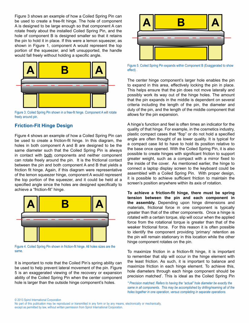
It is important to note that the Coiled Pin’s spring ability can be used to help prevent lateral movement of the pin. Figure 5 is an exaggerated viewing of the recovery or expansion ability of the Coiled Spring Pin when the center component hole is larger than the outside hinge component’s holes.
The center hinge component’s larger hole enables the pin to expand in this area, effectively locking the pin in place. This helps ensure that the pin does not move laterally and possibly work its way out of the hinge holes. The amount that the pin expands in the middle is dependent on several criteria including the length of the pin, the diameter and duty of the pin, and the length of the middle component that allows for the pin expansion.
A hinge’s function and feel is often times an indicator for the quality of that hinge. For example, in the cosmetics industry, plastic compact cases that “flop” or do not hold a specified angle are often thought of as lower quality. It is typical for a compact case lid to have to hold its position relative to the base once opened. With the Coiled Spring Pin, it is also possible to create hinges with significant friction to support greater weight, such as a compact with a mirror fixed to the inside of the cover. As mentioned earlier, the hinge to connect a laptop display screen to the keyboard could be assembled with a Coiled Spring Pin. With proper design, it is possible to achieve sufficient friction to maintain the screen’s position anywhere within its axis of rotation.
To achieve a friction-fit hinge, there must be spring tension between the pin and each component in the assembly. Depending upon hinge dimensions and materials, frictional force in one component is typically greater than that of the other components. Once a hinge is rotated with a certain torque, slip will occur when the applied force from the rotational torque is greater than that of the weaker frictional force. For this reason it is often possible to identify the component providing ‘primary’ retention as the pin will remain stationary in this location while the other hinge component rotates on the pin.
To maximize friction in a friction-fit hinge, it is important to remember that slip will occur in the hinge element with the least friction. As such, it is important to balance and maximize friction in each hinge element. To achieve this, hole diameters through each hinge component should be precision matched*. This is ideal as the Coiled Spring Pin
* Precision matched: Refers to having the “actual” hole diameter be exactly the same in all components. This may be accomplished by drilling/reaming all of the holes together in one operation, versus completing in separate operations.
Figure 3. Coiled Spring Pin shown in a free-fit hinge. Component A will rotate freely around pin.
A B A
Figure 4. Coiled Spring Pin shown in friction-fit hinge. All holes sizes are the same.
A B A
Figure 5. Coiled Spring Pin expands within Component B (Exaggerated to show effect) .
Tip: Note that the chamfer is stands proud of component B. This helps ensure maximum engagement of the pin with component B.
** Nominal Diameter: For a 4mm ∅ x 16mm length Coiled Spring Pin, the pin would measure larger than 4mm if it were sitting on a table. While the pin is larger than 4mm in its “free-state,” the nominal diameter is referred to as 4mm.
will be uniformly compressed in precision matched holes, and will exert a constant amount of tension on the hinge components.
An engineering drawing may read such that the holes in hinge components are precision matched, but what the holes actually measure in the production parts may be different from the print. It is always important to use calibrated gage pins to evaluate the diameter of the actual holes.
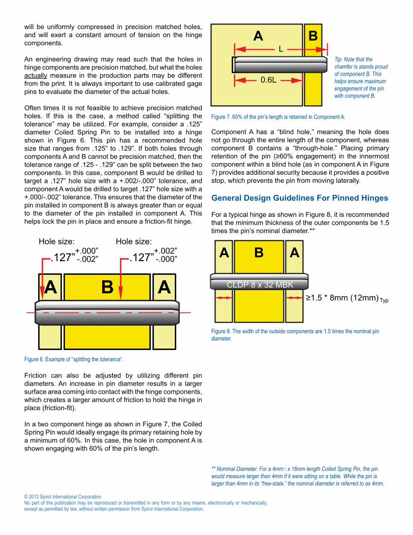
Often times it is not feasible to achieve precision matched holes. If this is the case, a method called “splitting the tolerance” may be utilized. For example, consider a .125” diameter Coiled Spring Pin to be installed into a hinge shown in Figure 6. This pin has a recommended hole size that ranges from .125” to .129”. If both holes through components A and B cannot be precision matched, then the tolerance range of .125 - .129” can be split between the two components. In this case, component B would be drilled to target a .127” hole size with a +.002/-.000” tolerance, and component A would be drilled to target .127” hole size with a +.000/-.002” tolerance. This ensures that the diameter of the pin installed in component B is always greater than or equal to the diameter of the pin installed in component A. This helps lock the pin in place and ensure a friction-fit hinge.
Friction can also be adjusted by utilizing different pin diameters. An increase in pin diameter results in a larger surface area coming into contact with the hinge components, which creates a larger amount of friction to hold the hinge in place (friction-fit).
In a two component hinge as shown in Figure 7, the Coiled Spring Pin would ideally engage its primary retaining hole by a minimum of 60%. In this case, the hole in component A is shown engaging with 60% of the pin’s length.
Component A has a “blind hole,” meaning the hole does not go through the entire length of the component, whereas component B contains a “through-hole.” Placing primary retention of the pin (≥60% engagement) in the innermost component within a blind hole (as in component A in Figure 7) provides additional security because it provides a positive stop, which prevents the pin from moving laterally.
General Design Guidelines For Pinned Hinges
For a typical hinge as shown in Figure 8, it is recommended that the minimum thickness of the outer components be 1.5 times the pin’s nominal diameter.**
Figure 6. Example of “splitting the tolerance”.
A B A
+.000”-.002”
+.002”-.000”.127”.127”
Hole size: Hole size:
A BL
0.6L
Figure 7. 60% of the pin’s length is retained in Component A.
B AA
CLDP 8 x 32 MBK≥1.5 * 8mm (12mm) Typ
Figure 8. The width of the outside components are 1.5 times the nominal pin diameter.
If the thickness of the outer components is less than 1.5 times the pin’s diameter, then the primary retention of the pin should be in the inner hole. To help understand what “nominal diameter” means, here is an example of how Coiled Spring Pins are identified:
The nominal diameter for this pin is 8mm, as indicated by the red circle in Figure 9. Therefore, as a general rule, the pin should be engaged at least 1.5 * 8mm, or 12mm, as shown in Figure 8.
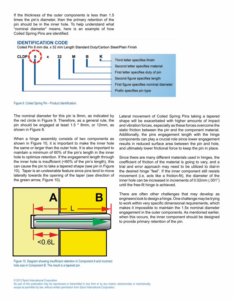
When a hinge assembly consists of two components as shown in Figure 10, it is important to make the inner hole the same or larger than the outer hole. It is also important to maintain a minimum of 60% of the pin’s length in the inner hole to optimize retention. If the engagement length through the inner hole is insufficient (<60% of the pin’s length), this can cause the pin to take a tapered shape (see pin in Figure 10). Taper is an undesirable feature since pins tend to move laterally towards the opening of the taper (see direction of the green arrow, Figure 10).
Lateral movement of Coiled Spring Pins taking a tapered shape will be exacerbated with higher amounts of impact and vibration forces, especially as these forces overcome the static friction between the pin and the component material. Additionally, the pins engagement length with the hinge components can play a crucial role since lower engagement results in reduced surface area between the pin and hole, and ultimately lower frictional force to keep the pin in place.
Since there are many different materials used in hinges, the coefficient of friction of the material is going to vary, and a trial and error approach may need to be utilized to dial-in the desired hinge ”feel”. If the inner component still resists movement (i.e. acts like a friction-fit), the diameter of the inner hole can be increased in increments of 0.02mm (.001”) until the free-fit hinge is achieved.
There are often other challenges that may develop as engineers look to design a hinge. One challenge may be trying to work within very specific dimensional requirements, which makes it impossible to maintain the 1.5x nominal diameter engagement in the outer components. As mentioned earlier, when this occurs, the inner component should be designed to provide primary retention of the pin.
Figure 9. Coiled Spring Pin - Product Identification.
A BL
<0.6L
Figure 10. Diagram showing insufficient retention in Component A and incorrect hole size in Component B. The result is a tapered pin.
When a Coiled Spring Pin is installed in this fashion, it has a “sized end” and “unsized end”. Figure 11 shows an example of a sized end and unsized end of a Coiled Spring Pin. Since the pin is larger than its host hole, it is compressed as it is inserted. As it travels through the hole, the pin’s diameter is decreased along the portion that contacts the hole. Once installed, one end of the pin will have traveled through the hole (Figure 11, sized end) while the other has not (unsized end). To set the hole tolerance for a free-fit hinge, the engineer should install the pin into the center component, and measure the diameter of the “unsized” end. Then add a factor to provide some clearance for the rotating member, usually .001” (0.02mm) to establish the minimum diameter of the free hole.
Additional Benefit Of Coiled Spring Pin
A major benefit of the Coiled Spring Pin for hinge applications is that it comes in a variety of duties including light, standard, and heavy. This refers to the gauge thickness of the strip material used to form the pin. Light duty has the thinnest gauge and heavy duty has the thickest, as seen in Figure 12.
UnsizedEnd
SizedEnd
This part of pin doesnot come into contactwith the hole, and thus,it is referred to as theunsized end.
Pin is installed from right to left
Figure 11. Sizing of Coiled Spring Pins.
Each duty has been specifically designed for use in certain materials. For example, light duty Coiled Spring Pins offer increased flexibility and are ideal for use in plastic hinges. In hinges made out of unhardened steels, standard duty Coiled Spring Pins are the best option, and for hinges made out of hardened steels, heavy duty may be the optimal choice. While there are exceptions, these guidelines typically result in the appropriate Coiled Spring Pin duty selection. A common cause of walking or lateral movement is improper choice of pin duty. Installing too rigid a pin in a flexible or easily damaged host material can result in hole deformation which can influence taper in the pin as the hinge is continuously actuated.
Figure 13 displays the stress distribution of the three different duties of Coiled Spring Pins installed in plastic holes. This picture is a top view of the pins installed into the plastic host material, and the “wavy lines” shown around the pin diameter reflect the stress magnitude. The light duty Coiled Spring Pin has the lowest stress level, and the heavy duty has the highest stress level, making it inappropriate for use in plastic hinges. (The light duty is the optimal choice for plastic hinges.)
Figure 13. Stress distribution of various duties of Coiled Spring Pins.
Conclusion
These guidelines provide the basis of establishing functional, high quality free-fit or friction-fit hinges using Coiled Spring Pins. These guidelines are however general, and there may be application specific considerations requiring deviation. It is recommended that Application Engineers who specialize in fastening and joining be consulted to ensure the optimum hinge design is employed for each application.
Spirol Asia Headquarters1st Floor, Building 22, Plot D9, District D No. 122 HeDan Road Wai Gao Qiao Free Trade Zone Shanghai, China 200131Tel. +86 21 5046 1451/1452Fax. +86 21 5046 1540
Europe
Americas
Asia Pacific
Technical Centers
SPIROL Application Engineers will review your application needs and work with your design team to recommend the best solution. One way to start the process is to visit our Optimal Application Engineering portal at www.SPIROL.com.