56
Hinkley Point C: Temporary Jetty Development Cliff Stability Assessment June 2011
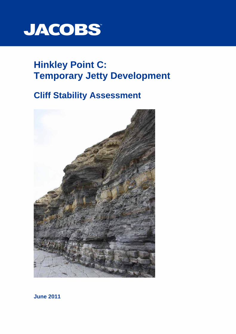
Hinkley Point C: Temporary Jetty Development Cliff Stability Assessment
June 2011

Document control sheet BPP 04 F8
Client: NNB Generation Company Limited Project: Hinkley Point C: Temporary Jetty
Development Job No: B1454110
Document Title: Cliff Stability Assessment
Originator Checked by Reviewed by Approved by NAME NAME NAME NAME ORIGINAL Jane Thrasher Allan Dishington Allan Dishington Ian Higham
DATE SIGNATURE SIGNATURE SIGNATURE SIGNATURE 18 May 2011
931773 718087
718087
pp
931773
Document Status
NAME NAME NAME NAME REVISION 0 Jane Thrasher Allan Dishington Allan Dishington
DATE SIGNATURE SIGNATURE SIGNATURE SIGNATURE 9 June 2011
513720 373694
373694
Document Status
NAME NAME NAME NAME REVISION
DATE SIGNATURE SIGNATURE SIGNATURE SIGNATURE
Document Status
Jacobs Engineering U.K. Limited This document has been prepared by a division, subsidiary or affiliate of Jacobs Engineering U.K. Limited (“Jacobs”) in its professional capacity as consultants in accordance with the terms and conditions of Jacobs’ contract with the commissioning party (the “Client”). Regard should be had to those terms and conditions when considering and/or placing any reliance on this document. No part of this document may be copied or reproduced by any means without prior written permission from Jacobs. If you have received this document in error, please destroy all copies in your possession or control and notify Jacobs. Any advice, opinions, or recommendations within this document (a) should be read and relied upon only in the context of the document as a whole; (b) do not, in any way, purport to include any manner of legal advice or opinion; (c) are based upon the information made available to Jacobs at the date of this document and on current UK standards, codes, technology and construction practices as at the date of this document. It should be noted and it is expressly stated that no independent verification of any of the documents or information supplied to Jacobs has been made. No liability is accepted by Jacobs for any use of this document, other than for the purposes for which it was originally prepared and provided. Following final delivery of this document to the Client, Jacobs will have no further obligations or duty to advise the Client on any matters, including development affecting the information or advice provided in this document. This document has been prepared for the exclusive use of the Client and unless otherwise agreed in writing by Jacobs, no other party may use, make use of or rely on the contents of this document. Should the Client wish to release this document to a third party, Jacobs may, at its discretion, agree to such release provided that (a) Jacobs’ written agreement is obtained prior to such release; and (b) by release of the document to the third party, that third party does not acquire any rights, contractual or otherwise, whatsoever against Jacobs and Jacobs, accordingly, assume no duties, liabilities or obligations to that third party; and (c) Jacobs accepts no responsibility for any loss or damage incurred by the Client or for any conflict of Jacobs’ interests arising out of the Client's release of this document to the third party.

Contents
1 Introduction and Context 1 1.1 Introduction 1 1.2 Objectives and Scope of Work 1 1.3 Limitations 1
2 Existing Site Condition 3 2.1 Site Description 3 2.2 Geology 3 2.3 Geomorphological Processes 5
3 Proposed Jetty Construction Works in Cliff Area 7 3.1 General Description 7 3.2 Selection of Pile Positions 8 3.3 Specific Works in the Cliff Area 8 3.4 Construction Activities in the Cliff Area 9
4 Construction Stability Assessment 12
5 Overall Impact of Construction on Cliff Stability 14 5.1 Long Term Natural Cliff Stability 14 5.2 Impact of Construction Works on Cliff Stability 14 5.3 Overall Impact of Construction Works on Cliff Stability 15 5.4 Implications for Site Reinstatement 15 Table 2-A Geological Section in Cliff 4 Appendix A References Appendix B Figures Appendix C April 2011 Site Visit and Stability Assessment Appendix D Excerpts from Amec Geological Survey

Hinkley Point C: Temporary Jetty Development, Cliff Stability Report, Rev 0 June 2011 1
1 Introduction and Context
1.1 Introduction
NNB Generation Company Limited (part of EDF Energy and hereafter referred to as EDF Energy) is seeking consent from the Marine Management Organisation (MMO) for the development of a temporary jetty and associated onshore infrastructure at Hinkley Point, Somerset (i.e. the ‘jetty development’). Consent will be sought by way of a Harbour Empowerment Order (HEO) under The Harbours Act 1964 (as amended) and licences under the Food & Environment Protection Act 1985 (FEPA). The temporary jetty development is proposed as part of the Preliminary Works to support construction of the Hinkley Point C new nuclear power station (herein referred to as the Hinkley Point C Project). EDF Energy is seeking a Development Consent Order (DCO) for the Hinkley Point C Project from the Infrastructure Planning Commission (IPC) under the Planning Act 2008. If a DCO is not granted for the Hinkley Point C Project, then the proposed development provides for the removal of the jetty’s infrastructure and works and reinstatement of the application site. Otherwise the temporary jetty is to be removed on completion of construction of the Hinkley Point C Project. This report has been prepared in response to certain representations made to the MMO by Third Parties following submission of the HEO application. The representations addressed in this report relate to the specific impact of the jetty construction on the Hinkley Cliff, in particular the stability of the cliff. Therefore in this report only the specific aspects of the jetty development which might have a particular impact on the cliff stability are detailed. This includes works associated with jetty construction which might potentially affect cliff stability. 1.2 Objectives and Scope of Work
The objectives of this study are to: • Provide a detailed assessment of the impact of jetty construction works on
cliff stability, in particular with respect to feasibility of site reinstatement. The scope of work has involved: • Site visit by Engineering Geologist to undertake detailed inspection of cliff; • Site visit by Geomorphologist to undertake detailed assessment of the
erosion mechanism of the cliff and foreshore; • Review of existing technical documents assessing coastal geomorphology
and cliff geology; • Assessment of existing cliff stability; • Review of proposed jetty construction works in area of cliff; • Assessment of impact of construction on cliff stability. 1.3 Limitations
This report is largely based on information regarding outline design and construction, as detailed in the Environmental Statement for Jetty Development (Reference 5, Appendix A), together with consideration of more recent detailed

Hinkley Point C: Temporary Jetty Development, Cliff Stability Report, Rev 0 June 2011 2
design proposals for the jetty. The detailed design includes consideration of mitigation measures, in order to reduce any impacts on the cliff. These have been taken into account in this report. The actual construction methods to be used are yet to be confirmed, but will be detailed in the contractor’s method statements, which will be required to comply with the mitigation measures in the design. This report is based on a site visit by Jacobs in April 2011 and review of third party documents. It is recognised that the Hinkley Cliff is a dynamic environment and the site visit provides only a snapshot of conditions at one time. The conclusions of this report are based on these results together with professional judgement and general geological experience. This report is not a health and safety risk assessment. Prior to any work on the cliff or foreshore, any contractors must undertake their own health and safety risk assessment and develop a method statement appropriate to the task and risk.

Hinkley Point C: Temporary Jetty Development, Cliff Stability Report, Rev 0 June 2011 3
2 Existing Site Condition
The existing site condition has been assessed from the following sources: • Jacobs site visit on 18th April 2011, file notes and site photographs; • Geological Survey and Mapping, June 2009, AMEC, (Ref. 1, Appendix A),
based on site visits undertaken on 9th-12th January 2009; • ‘Coastal Hydrodynamics and Geomorphology’, Chapter 9, Environmental
Statement, November 2010, EDF Energy (Ref. 2, Appendix A). It should be noted that while the AMEC report (Ref 1, Appendix A) includes some detailed geological survey and mapping of the area, including the subject cliff, the primary purpose of the mapping was to assess the stratigraphic sequence at the site and not the morphology and stability of the cliff itself. Key excerpts of the AMEC report are reproduced in Appendix D. 2.1 Site Description
The site assessed here comprises a cliff-top, cliff and foreshore. At the time of the site visit in April 2011 the cliff-top comprised a relatively level grassed field with a 3m zone extending back from the cliff edge that is vegetated with brambles and longer grasses. There is no fence. No close inspections were undertaken within this 3m vegetated zone at the cliff edge for health and safety reasons, nevertheless no indicators of cliff instability were observed at the cliff-top. The cliff itself is approximately 7m to 8m in height, largely vertical and aligned generally east to west. It is made up of interbedded Blue Lias mudstones and limestones exhibiting varying degrees of weathering. Plate 5 was taken at the point the jetty is proposed to cross the cliff. The cliff is described in more detail below. The upper foreshore comprises a natural limestone pavement, dipping at a shallow angle away from the cliff, and formed of one of the hard limestone bands. In April 2011 this pavement was observed to extend for some 10m from the cliff. Further down, the foreshore is covered in a veneer of mud, boulders and seaweed. At the time of the site visit the seaweed line indicating the high tide mark was some 80m from the cliff line. The base of the cliff is understood to form the limit of spring tide / storm tide. 2.2 Geology
The geology of the site and area are described in detail in the AMEC report (Ref. 1 Appendix A). The exposed geology comprises interbedded limestones and mudstones of the Lower Jurassic Lower Lias. The limestone forms hard continuous bands typically 0.1 to 0.3m thick, while the mudstone (also sometimes referred to as shale) bands are softer and up to 2m thick. There are no major faults in the area of the jetty development, although the Hinkley Point Fault is mapped about 2km east of the site. At the point of the proposed jetty development the bedding runs more or less parallel to the cliff, and has a shallow dip of 7° to 10° in a dip direction of around

Hinkley Point C: Temporary Jetty Development, Cliff Stability Report, Rev 0 June 2011 4
345°, that is, down the foreshore. The foreshore thus comprises a gently sloping limestone pavement extending for 10m away from the cliff. Beyond this the foreshore is covered in a veneer of mud, shingle and seaweed, with the hard limestone bands exposed as reefs. The dip of the bedding results in the geological units exposed in the cliff being successively re-exposed in out-crop on the foreshore. Several hundred metres to the west, the bed forming the limestone pavement is exposed as approximately 0.3m in thickness and overlying a 2.0m thick mudstone layer. This limestone band is identified by AMEC (Ref. 1) as persistent Limestone Unit 109, and their logs are consistent with the Jacobs site observations. The cliff itself could not be examined in detail at close proximity (i.e. to give measured sections of the rockface or to collect and examine samples of outcrop) due to its instability, but observations were made from a safe distance several metres back on the foreshore. The following section can be derived from the AMEC logs (Ref. 1) and Jacobs site photographs and records:
Unit (from AMEC, Ref. 1) Approx. Thickness (m) From AMEC Log TC18
Comments
Persistent Limestone 130-134 0.7m Within strongly weathered zone, ca. 1m from top of cliff
Shale 127-129 with lenticular limestone ca. 0.25m from base
1.35m Forms main overhang and weathered area.
Persistent Limestone 126 0.35m Distinctive yellow-brown band immediately below overhangs; fresh surfaces are grey.
Shale with one 0.12 limestone unit and two bands of calcareous nodular shale 125-115
2.3m Main vertical cliff
Persistent Limestone 114 0.2m Basal section of vertical cliff Shale 112-113 0.03m Basal section of vertical cliff Nodular Limestone 112-113 0.16m Basal section of vertical cliff Shale 112-113 0.36m Basal section of vertical cliff Persistent Limestone Unit 111 0.12m Basal section of vertical cliff Shale 110 0.13m Basal section of vertical cliff Persistent Limestone Unit 109 0.1m Forms continuous limestone pavement on
foreshore. Very hard.
Table 2-A Geological Section in Cliff
It was observed that where limestone bands are exposed on the beach or in the cliff section it occurs as a strong rock. This limestone fractures along bedding and joint planes with the blocks that are formed having dimensions approximately equal to the bed thickness. These fractured rectangular blocks fall out of the cliff or pavement and are transported eastwards by tidal processes during which they become reduced in size by abrasion and other processes. The mudstone exposed varies between heavily and completely weathered, weak to extremely weak, often fracturing on extremely close discontinuities. It is possible that

Hinkley Point C: Temporary Jetty Development, Cliff Stability Report, Rev 0 June 2011 5
some of the mudstone that is less weathered is calcareous as it is more homogeneous and more massive. The base of the cliff is made up of several thick hard limestone bands which may offer some protection to the cliff toe at this location. The first four to five metres of the cliff face appears relatively flatly bedded (with strike parallel to the cliff face), this is the zone assumed to be affected by storm and wave action. Above this zone is an area of rock overhang that is approximately two to three metres high, where wave action is assumed not to reach. Cracks can be seen running behind these overhangs, running for several meters vertically up the cliff face and up to 70mm wide. The top two to three metres of the cliff are very heavily weathered with the mudstone completely weathered to a soil, where this is not supported by the vegetation at the top of the cliff it slopes up at approximately 45°. Blocks of lenticular limestone stand out as un-weathered material. The shallow dip of the geological bedding planes towards the foreshore enhance natural erosion of the cliff. 2.3 Geomorphological Processes
The Hinkley Cliff is a dynamic geomorphological environment with active coastal erosion. Estimates of cliff erosion rates vary. Chapter 9 (Coastal Hydrodynamics and Geomorphology) of the 2010 ES (Ref. 3), refers to a study by Rendel, Palmer and Tritton (RPT), undertaken in 1986 to inform a previous ES for the proposed new Hinkley C Power Station (not seen in this study). This RPT study concluded that shoreline retreat resulting from coastal erosion was at a rate of 0.1 to 0.5m/yr. However the 2010 ES (Ref. 3) notes that ‘this assertion was based upon a limited study period of 30 months during which the results could have been sensitive to short term environmental fluctuations. Moreover, their findings did not allow for anticipated rise in sea level and other climatic changes.’ A separate study by Halcrow (2007, Ref. 4) also cited in the 2010 ES (and not seen in this study), defined a series of coastal units around Hinkley Point, and noted historic evidence for and magnitudes of coastal change. The coastal unit covering the location of the proposed jetty development contained evidence to indicate that the interbedded limestones and shales of the Blue Lias cliff top have retreated at around 0.13m/yr since 1888, and mean high water mark by around 0.04m/yr. Rates of coastal recession are strongly influenced by storm events and will not be consistent from year to year, therefore any estimate only provides a long term average and not an indication of short term events. The main cliff erosion mechanisms are believed to be wave undercutting, particularly during storm events. There are other processes leading to erosion (e.g. frost - thaw of groundwater within jointing), and storm events are expected to mainly remove material which has been loosened by these other processes. The site visit indicated the presence of fractures in the cliff, which are likely to develop in response to stresses induced by undercutting, but will be enlarged by frost – thaw processes during the winter months. Excess groundwater pressure behind the face of the cliff is also expected to be a mechanism leading to spalling from the cliff. The frequency of major storms with the potential to result in significant cliff erosion is not known, however the process is considered likely to occur during normal winter storms, i.e. with a minimum frequency of several occasions during one year.

Hinkley Point C: Temporary Jetty Development, Cliff Stability Report, Rev 0 June 2011 6
Evidence of continuous small scale erosion at the site includes observations of small rock falls occurring during the April 2011 visit, and the presence of occasional limestone boulders on the foreshore below new scars. It is evident from the absence of further rock or boulders on the upper foreshore that cliff derived debris is rapidly moved along the coast by tidal movements and currents. Comparison of photographs of the cliff in the area of the jetty development in January 2009 (AMEC (2009), Figure 15, ref. 1, Appendix A) and April 2011 (Jacobs site visit) show significant changes to the cliff morphology. While the foreshore pavement, geological succession and location information indicate clearly that the Amec photograph is from the same stretch of cliff as that visited by Jacobs, the cliff has changed so much that it is difficult to be sure whether the photographs are of the same section. Figure 1 compares two photographs which could be of the same section of cliff, illustrating the dynamic nature of the cliff erosion (see Figure 1, Appendix B). The January 2009 photographs shows fresh angular fracture surfaces in the mudstone in the upper section of the cliff. These are indicative of very recent cliff falls. There is no sign of such angular surfaces in the April 2011 photographs, indicating they have been smoothed by weathering processes. Comparison of the January 2009 and April 2011 photographs shows several sections of rock which have been lost in the intervening period, in particular a large block of mudstone from the upper over-hanging section, and a distinctive protruding piece of limestone from Unit 126 from the upper part of the vertical cliff. Other less easily discernible changes are also likely to be present.

Hinkley Point C: Temporary Jetty Development, Cliff Stability Report, Rev 0 June 2011 7
3 Proposed Jetty Construction Works in Cliff Area
The proposed development of the temporary jetty is described in detail in Chapter 6 of the 2010 ES (Ref. 5, Appendix A), with features pertinent to this study described here. The detail design includes consideration of mitigation regarding potential cliff damage. The contractor’s method of construction will be reviewed in this regard. The jetty description below incorporates additional / updated information from the detail design... 3.1 General Description
The temporary jetty structure comprises a jetty bridge nearly 500m long linking an off-shore jetty head with an on-shore aggregate store and contractor’s site compound. The jetty bridge comprises a 5m roadway bridge and a conveyor bridge running parallel but separated by a gap of some 1m. The jetty bridge will rise gently from an elevation of 13.5m aOD (above Ordnance Datum) at the jetty head, to 20m aOD at the landward end. The line of the jetty is oblique to the cliff line. The road bridge comprises a precast concrete deck on steel beams, which are supported on concrete crossheads positioned at 30.5m centres along the line of the bridge. The crossheads are supported on steel tubular raking piles which are installed through the sea bed / cliff top materials into a rock socket. There are either 2, 4 or 6 piles per crosshead depending on crosshead structural function. Rainfall run-off would drain directly into the sea. The conveyor bridge is a contractor design element but is anticipated to comprise a steel box truss structure spanning the 30.5m and supported on the same crossheads as the road bridge. The truss structure would incorporate a pipeline for transporting cement on its western side, a conveyor for aggregates on its eastern side and service ducts along its internal western face. The walkway deck would be an open mesh floor and rain water would discharge direct into the sea... The landside support to the road and conveyor bridges is a single bankseat located some 45 m back from the cliff. The bankseat is a reinforced concrete structure supported on a pile group. It is proposed that the offshore piles will be driven through the superficial sea bed deposits and weathered rock strata to competent rock head level. A rock socket will then be drilled to a depth of some 6 – 8 m into competent rock, to a diameter a little larger than the pile. The socket will then be filled with concrete and the steel tubular pile will be installed into the wet concrete socket. The pile installation landward of the cliff will utilise a similar socket approach but the initial installation to rock head would be undertaken in a manner to mitigate potential impact to the cliff face (see Sections 3.3 and 3.4)... According to the ES, where the jetty bridge connects to the land, it would be necessary to cross over the coastal footpath and, therefore, minor works may be required to ensure that all health and safety requirements would be met. However, during the detail design stage, it was concluded that the coastal footpath would be closed.
Hinkley Point C: Temporary Jetty Development, Cliff Stability Report, Rev 0 June 2011 8
3.2 Selection of Pile Positions
During the detail design process the positioning of the piles relative to the cliff was carefully considered in order to mitigate effects on the cliff face. The main factors include: • The 30.5 m bridge spans allowed the pile bents to be positioned either side
of the cliff face and the bridge deck to span over the cliff face, thus avoiding loading of the ground immediately behind the face.
• It was considered that the pile installation behind the cliff face could have
potentially greater impact on the cliff compared to the seaward piles. The landward piles are installed through an additional 10 m of superficial / weathered rock strata compared to the seaward piles which are installed direct into the exposed beach rock layer.
• As the landward piles were considered more sensitive in respect of potential
cliff impacts, the overall pile arrangement was positioned such that the landward piles were further away from the face compared to the seaward piles.
• The installation plant positioned on top of the cliff has greater potential to
affect the cliff compared to plant positioned on the beach. Hence again it was considered better to position the landward piles further back from the cliff face compared to the seaward piles.
• The cliff is susceptible to gradual erosion and whilst the jetty is only
temporary (nominal 10 years) it was considered better to locate the landward piles further back from the face to help mitigate erosion risks on the piles.
• In conclusion, it was considered better to position the pile groups eccentric
on the cliff face, with the landward piles set further away from the face compared to the seaward piles.
3.3 Specific Works in the Cliff Area
The design drawings (Figures 2 and 3, see Appendix B) show the following structures in the immediate vicinity of the cliff: Foreshore • Two steel piles sunk in the foreshore, approximately 10 m and 12 m
respectively from the cliff line, and approximately 6.5 m apart at crosshead level (raking outwards towards the beach);
• It is anticipated that the foreshore piles will penetrate some 6 m through the weathered / weaker rock strata (at the surface on the upper foreshore) and then be installed into a predrilled and concreted rock socket extending a further 6 m into competent rock strata ;
• The foreshore piles are expected to be constructed by boring through both the weathered / weaker strata and the competent rock strata;
• Concrete crosshead linking the foreshore steel piles and subsequent placing of the bridge deck elements.
Landside

Hinkley Point C: Temporary Jetty Development, Cliff Stability Report, Rev 0 June 2011 9
• Two steel piles sunk in the landside of the cliff, approximately 17 m and 15 m respectively from the cliff line, and approximately 6.5 m apart at crosshead level (raking outwards towards the beach);
• Piles to be installed through the superficial and weathered / weaker rock strata into a predrilled and concreted rock socket extending some 6 m into competent rock strata. (The ES does not distinguish pile depths on land from off-shore; however it is anticipated that they will be required to penetrate to a depth at or below the depth of the cliff height due to the thick weathered zone observed, and the presence of a thicker mudstone layer in this area – hence the rock socket is anticipated to lie below the toe of cliff level);
• Concrete crosshead linking the landside steel piles and subsequent placing of the bridge deck elements.
3.4 Construction Activities in the Cliff Area
The construction activities were discussed in the Environmental Statement and further developed during the detail design process, as discussed below. According to the ES (Ref. 5): “The piling installation method is anticipated to be either by drilling and driving or by pre-drilling and concreting the pile into the socket, subject to further ground investigation data.” “With the drill and drive method, the pile is seated onto the rock head, a drill is inserted down the pile shaft and a hole drilled into the rock mass; the pile is then driven into the hole, the hole is extended and the pile is driven further into the hole until the required penetration is achieved. This technique would generate a degree of piling noise but is not anticipated to create much in the way of bed disturbance.” There would however be expected to be significant ground vibration with this ‘drilled and driven’ method of pile installation. “The alternative pile installation method is for the pile to be placed into a concrete filled rock socket. The pile is firstly driven to rock head, a drill is inserted down the pile and the rock socket is drilled and then enlarged using the under-reaming blades to a diameter greater than the pile. Concrete is placed into the rock socket and the pile is driven into the wet concrete. Shear rings on the pile provide a degree of tension capacity.” Minimal ground vibration is expected with this ‘bored and plunged’ method of pile installation. “Once the piles are driven, concrete cross heads would be placed over the pile bents. It is anticipated that the cross head units would be pre-cast with in situ stitching to the pile.” “The steel box truss structure units would be prefabricated in lengths that span between cross head supports. The prefabricated units would incorporate the steel longitudinal and transverse deck beams. It is also anticipated that the cement pipeline, aggregate conveyor and open mesh flooring would be installed within the units whilst on-shore.” “The inshore end of the jetty bridge, including the first few spans across the upper foreshore, would be installed using land based plant. For the drilling and placing of the tubular piles it is anticipated that various plant would be required for the installation of approximately one pile per day, including a 120t crawler crane, 30t

Hinkley Point C: Temporary Jetty Development, Cliff Stability Report, Rev 0 June 2011 10
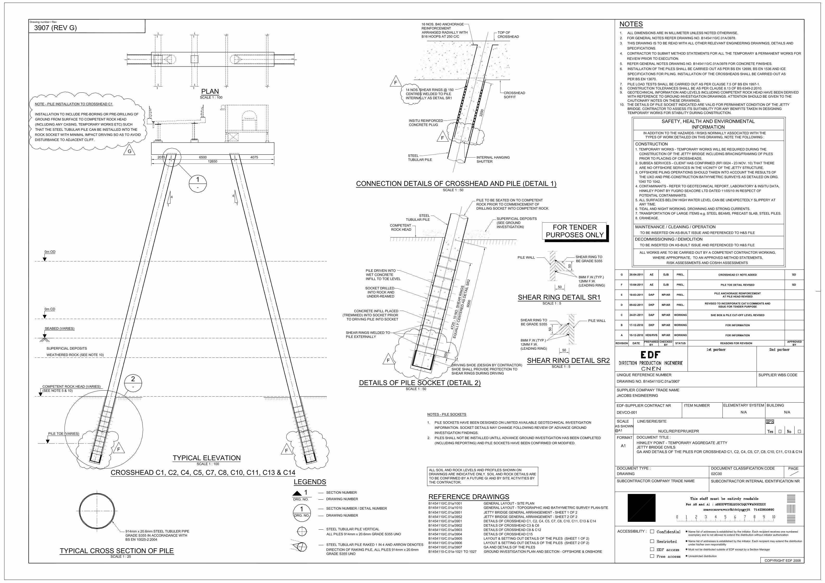
excavator with drill attachment, piling hammer, 20t excavator to load spoil and 25t dump truck to remove spoil (4-6 loads per day). It is envisaged that this would result in approximately 10 vehicles per day, including 3-4 concrete deliveries. In addition, piles would be brought to site by barge and tug, at a rate of one delivery per week.” During the detail design process the pile installation approach was developed and has subsequently been identified on the tender drawings (reproduced as Figures 4 and 5, Appendix B) and in the specification. Relevant pile installation methodology and requirements include: • The majority of piles located on the foreshore and off-shore are installed by
driving the pile through the superficial / sea bed deposits into the weathered / weaker rock strata. The inside of the pile is then cleaned out, a drill bit is inserted down the pile and the socket drilled through the remainder of the weaker rock strata and then some 6 – 8 m into the competent rock strata, to a diameter a little larger than the pile. The socket in the competent rock is then filled with concrete and the pile is inserted into the wet concrete.
• The pair of piles installed immediately in front of the cliff face will not require
driving as there are no superficial deposits, the rock strata is exposed on the surface. The pile will be positioned on the exposed rock surface, a drill bit inserted down the pile and the socket drilled through the upper weaker rock strata and then some 6 – 8 m into the competent rock strata, to a diameter a little larger than the pile. The socket in the competent rock is then filled with concrete and the pile inserted into the wet concrete.
• The pair of piles installed immediately behind the cliff face are to be installed
in a manner which avoids impact driving of the pile through the superficial deposits and weathered / weaker rock strata. It is specified that a pre-drilled / cased hole will be formed in these upper strata and the pile then installed into the hole after which drilling and forming of the concreted rock socket will take place. This approach has been described on the drawings with a note stating “Note – Pile installation to crosshead C1 – Installation to include pre-boring or pre-drilling of ground from surface to competent rock head ( including any casing, temporary works etc ) such that the steel tubular pile can be installed into the rock socket with minimal impact driving so as to avoid disturbance to adjacent cliff” (see drawing 3907, reproduced as Figure 4, Appendix B).
• The construction of the bank seat will include pile installation. The bank seat
is located some 45 m behind the cliff face and partly buried in the landfill plateau. Whilst these piles are a substantial distance behind the cliff we have taken a precautionary approach and incorporated the following note on the drawings “The form of pile shall be such as to avoid any significant ground vibration / movement which may cause damage to the adjacent cliff. Pile shall be augured / drilled, cast in situ type or other form as accepted by the Project Manager” (see drawing 3911, reproduced as Figure 4, Appendix B )

Hinkley Point C: Temporary Jetty Development, Cliff Stability Report, Rev 0 June 2011 11
The primary construction route will be from the land orthogonal to the cliff face, and from the sea, orthogonal to the cliff face. Construction traffic along the foreshore is to be kept to a minimum. A temporary access route for small construction plant to gain access to the foreshore may be constructed at the existing low point between the jetty and Hinkley Point A. If required, traffic movements on the foreshore will be restricted to a 15m strip at the base of the cliff. This will be addressed within the Contractor’s Method Statements. Similarly construction plant movements parallel to the top of the cliff will be minimised with inland routes used in preference to cliff top routes. This shall be addressed within the Contractor’s Method Statements. .
Hinkley Point C: Temporary Jetty Development, Cliff Stability Report, Rev 0 June 2011 12
4 Construction Stability Assessment
Activities within the construction, operation and development with the potential to impact the cliff stability include: • Landside piling installation • Loading of landside piles • Loading from plant and materials positioned on the landside cliff during
construction • Foreshore piling installation • Tracking of heavy plant on temporary access roads on the foreshore e.g.
120t crane for bridge spans • Alteration of foreshore hydrodynamics to increase scour in the vicinity of jetty
foundations • Operation of the jetty including conveyor operation and vehicle traffic • Demolition including concrete breaking Additionally, mitigation measures will be required to protect workers on the foreshore from falling debris from the cliff. The measures implemented will depend on the pre-construction contractors risk assessment, but may include the construction of guards and netting, or ‘scaling’ of the cliff, i.e. removal by hand of the loosest materials. The stability assessment (Appendix C) assesses some of these risks. It is concluded: • The landside piles are set far enough back from the cliff for the area of
influence of the loaded pile to be outside the area of the cliff, even after 10 years erosion. The loaded piles are therefore unlikely to have any impact on the cliff stability.
• The area of influence of the foreshore piles is below the elevation of the cliff
and will not impact cliff stability. • Vibrations associated pile installation will depend on the method adopted.
Vibration could be minimised by the use of ‘bored and plunged’ piles as opposed to ‘drilled and driven’ methods. Vibrations associated piling on the foreshore are likely to be directly transmitted to the cliff via the hard limestone beds exposed on the foreshore. In the worst case, the effect of such vibrations is expected to be similar to severe winter storms, resulting in potential rockfalls of existing loose material.
• Vibrations associated with pile installation on the cliff-top (landside) are also
likely to be directly transmitted to the cliff via the hard limestone beds exposed on the cliff which will be encountered during landside piling. The limestone bands are expected to be very hard even in the weathered zone. Again the effect can be mitigated by the choice of pile installation method. In the worst case, the effect of vibrations is expected to be similar to severe winter storms, resulting in potential rockfalls of existing loose material.

Hinkley Point C: Temporary Jetty Development, Cliff Stability Report, Rev 0 June 2011 13
• Vibrations associated with heavy plant movements on the foreshore, and demolition activities such as concrete breaking on the foreshore, are likely to be directly transmitted to the cliff via the hard limestone beds exposed on the foreshore. The effect of such vibrations is expected to be similar to severe winter storms, resulting in potential rockfalls of existing loose material.
• It is also concluded that minor alterations to the locations of the piles that are
feasible within the scope of the design (e.g. moving the relative positions of the piles closer to or further from the cliff, within the restriction of the requirement for a 30.5m span) would not significantly alter the potential impact on the cliff.
• With regard to the risks associated with surcharge from loading of plant and
materials on the landside cliff, there is not anticipated to be any impact associated with plant and materials located further than 10m back from the edge of the cliff. It is anticipated that Contractors Method Statements will limit works within 10m of the cliff edge to a minimum. If works are required in this area they will require a Contractor’s risk assessment of safe working distance.
• Any vibrations associated with operation of the jetty are likely to be
transmitted to the rock sockets at depth below the level of the cliff; their effect on the cliff is therefore likely to be negligible.
The hydrodynamic impact of the jetty has been assessed in Chapter 9 (Coastal Hydrodynamics and Geomorphology) of the 2010 ES. This states: “Of particular relevance to coastal hydrodynamics and geomorphology, is the fact that the jetty design consists of an open piled structure which would minimise impacts on hydrodynamic processes. The use of a piled structure set at an oblique angle to the inter-tidal zone would also reduce the potential hydrodynamic impact. In addition, minimising as far as possible the number and diameter of piles and jetty uprights lowers the potential magnitude of impact on coastal hydrodynamics, sediment transport and scour. Ensuring that those piles placed closest to the shore are set at a maximum distance from the sea cliff is also a design consideration that would limit potential impacts, including impediment of sediment transport to the east. Iterations of the jetty design, discussed for example at MALG (Marine Authorities Liaison Group) consultation meetings, have already taken these proposals into account.”

Hinkley Point C: Temporary Jetty Development, Cliff Stability Report, Rev 0 June 2011 14
5 Overall Impact of Construction on Cliff Stability
5.1 Long Term Natural Cliff Stability
This study has demonstrated that the Hinkley Cliff is currently a dynamic receding cliff environment, with natural processes resulting in continuing recession of the cliff. This cliff recession will continue regardless of whether the jetty development is constructed or not. The rate of cliff erosion has been estimated at between 0.1 m/year and 0.5m/year as a long term average along the coast. However the rate of erosion is not expected to be consistent from year to year, or in any particular location. The amount of erosion which occurs at any particular point in any particular year is the result of a combination of factors including (but not limited to): • Nature and frequency of storm events • Weather conditions (e.g. freezing conditions following wet weather leading to
additional frost cracking) • Cliff condition and period since previous cliff fall The Jacobs April 2011 site visit indicates that the cliff in the area of the proposed jetty development is in a particularly precarious condition, with large cracks indicating that (at least in some sections) there has been a considerable period since the last major cliff fall, and there is likely to be a major cliff fall soon. It is not clear from the evidence available exactly how soon this fall will occur, but under natural conditions it appears highly likely that there will be a major cliff fall in the area in the next three years. There are also expected to be continued minor cliff falls. 5.2 Impact of Construction Works on Cliff Stability
The cliff stability assessment indicates that it is likely that the construction activities for the jetty development could result in loss of the existing loose material from the existing cliff, through vibration by heavy plant and piling. The material which will erode through this process is the material which would otherwise be lost in winter storms. Depending on timing of natural events such as storms, these rockfalls may occur sooner than might occur naturally, but the long term rate of erosion is considered unlikely to be altered. This is because, while it is the storms that trigger the main rockfalls, it is the longer term processes of wave erosion, undercutting and freeze/thaw, which lead to the cracks and loosen the material which then falls. Thus while there may be a period during and soon after construction when there are more freshly exposed rock faces on the cliff, the construction works will not speed up the long term processes of undercutting and freeze/thaw which serve to loosen the larger blocks on the cliff face. In other words, the cliff is going to erode and recede, either as a natural result of storms and weathering, or as a result of construction related vibration.

Hinkley Point C: Temporary Jetty Development, Cliff Stability Report, Rev 0 June 2011 15
5.3 Overall Impact of Construction Works on Cliff Stability
The overall long term (5-10 year) impact of the construction works on cliff stability is therefore anticipated to be negligible. However some recession and change to the cliff profile must be expected during the period of construction. 5.4 Implications for Site Reinstatement
As described in Section 1, if a DCO is not granted for the Hinkley Point C Project, then the proposed development provides for the removal of the jetty’s infrastructure and works and reinstatement of the application site. The implications for site reinstatement are that it would be impractical and inappropriate to expect the cliff to be reinstated to the pre-construction condition. Even without the construction works, natural changes to the cliff condition would be expected over a similar time period, as graphically illustrated in the comparison of photographs from January 2009 and April 2011.
Hinkley Point C: Temporary Jetty Development, Cliff Stability Report, Rev 0 June 2011
Appendix A References
1.) AMEC, June 2009, Geological Survey and Mapping, Issue 02 Final, Project Reference: 15122/TR/0011(5788001753/999). 2.) EDF, November 2010, Coastal Hydrodynamics and Geomorphology (Chapter 9), Environmental Statement, Hinkley Point C Preliminary Works, Temporary Jetty Development. 3.) Rendel, Palmer and Tritton, May1986, Hinkley Point ‘C’ Power Station Pre-Application Studies. For ‘Coastal Physiography’ chapter of Proposed Hinkley Point C Environmental Statement, August 1987, Central Electricity Generating Board. 4.) Halcrow, 2007, Review of medium to long-term coastal geohazard risks associated with British Energy sites. Report to British Energy Generation Ltd. Birmingham, UK, Halcrow Group Ltd. 5.) EDF, November 2010, Project Description: Temporary Jetty Development (Chapter 6), Environmental Statement, Hinkley Point C Preliminary Works, Temporary Jetty Development.
Hinkley Point C: Temporary Jetty Development, Cliff Stability Report, Rev 0 June 2011
Appendix B Figures
Figure 1: Comparison of Cliff Morphology Over Time Figure 2: EDF Energy Drawing Number: B1454110-C.01a-1001-REV F, Hinkley Point – Temporary Aggregate Jetty, General Layout, Site Plan Figure 3: EDF Energy Drawing Number: B1454110-C.01a-1002-REV B, Hinkley Point – Temporary Aggregate Jetty, General Layouts, Illustrative Site Long Section Figure 4: EDF Energy Drawing Number: B1454110-C.01a-3907-REV G, Hinkley Point – Temporary Aggregate Jetty, Jetty Bridge Civils, GA and Details of the piles for crosshead C1, C2, C4, C5, C7, C8, C10, C11, C13 & C14 Figure 5: EDF Energy Drawing Number: B1454110-C.01a-3911-REV F, Hinkley Point – Temporary Aggregate Jetty, Jetty Bridge Civils, General Arrangement of Bank Seat; Sheet 1 of 2

Distinctive cliff shape apparently still in place in April 2011
Protruding limestone in January 2009 absent in April 2011
Overhanging mudstone visible in January 2009 absent in April 2011
January 2009 (Amec, 2009) April 2011(Jacobs)
Angular surfaces indicating fresh breaks; not visible (and out of view) in April 11
Although not confirmed, these photographs may show the same section of cliff in 2009 and 2011


Hinkley Point C: Temporary Jetty Development, Cliff Stability Report, Rev 0 June 2011
Appendix C April 2011 Site Visit and Stability Assessment

EDF HINKLEY POINT C TEMPORARY JETTY DEVELOPMENT Cliff Stability at Jetty Crossing
Report Ref: B1454110/GEO 01 (Rev 0)
May 2011

Document control sheet BPP 04 F8
Client: NNB Generation Company Limited Project: Hinkley Point C
Temporary Jetty Development Job No: B 1454110
Document Title: Cliff Stability at Jetty Crossing
Ref Nr B1454110/GEO 01 (Rev 0)
Originator Checked by Reviewed by Approved by NAME NAME NAME NAME ORIGINAL
0 Dan Gough Alan Miles Allan Dishington Allan Dishington
DATE 17 May 2011 SIGNATURE SIGNATURE SIGNATURE SIGNATURE
718087
718087
Document Status : Draft for comment
NAME NAME NAME NAME REVISION: 0
Dan Gough Alan Miles Allan Dishington Allan Dishington
DATE :
09 June 2011
SIGNATURE SIGNATURE SIGNATURE SIGNATURE
373694
373694
Document Status : Original Issue
NAME NAME NAME NAME REVISION
DATE SIGNATURE SIGNATURE SIGNATURE SIGNATURE
Document Status
Jacobs Engineering U.K. Limited This document has been prepared by a division, subsidiary or affiliate of Jacobs Engineering U.K. Limited (“Jacobs”) in its professional capacity as consultants in accordance with the terms and conditions of Jacobs’ contract with the commissioning party (the “Client”). Regard should be had to those terms and conditions when considering and/or placing any reliance on this document. No part of this document may be copied or reproduced by any means without prior written permission from Jacobs. If you have received this document in error, please destroy all copies in your possession or control and notify Jacobs. Any advice, opinions, or recommendations within this document (a) should be read and relied upon only in the context of the document as a whole; (b) do not, in any way, purport to include any manner of legal advice or opinion; (c) are based upon the information made available to Jacobs at the date of this document and on current UK standards, codes, technology and construction practices as at the date of this document. It should be noted and it is expressly stated that no independent verification of any of the documents or information supplied to Jacobs has been made. No liability is accepted by Jacobs for any use of this document, other than for the purposes for which it was originally prepared and provided. Following final delivery of this document to the Client, Jacobs will have no further obligations or duty to advise the Client on any matters, including development affecting the information or advice provided in this document. This document has been prepared for the exclusive use of the Client and unless otherwise agreed in writing by Jacobs, no other party may use, make use of or rely on the contents of this document. Should the Client wish to release this document to a third party, Jacobs may, at its discretion, agree to such release provided that (a) Jacobs’ written agreement is obtained prior to such release; and (b) by release of the document to the third party, that third party does not acquire any rights, contractual or otherwise, whatsoever against Jacobs and Jacobs, accordingly, assume no duties, liabilities or obligations to that third party; and (c) Jacobs accepts no responsibility for any loss or damage incurred by the Client or for any conflict of Jacobs’ interests arising out of the Client's release of this document to the third party.

Contents
1 Introduction.................................................................................................2 1.1 General .........................................................................................................2
2 Geology........................................................................................................3
3 Inspection and Assessment ......................................................................4 3.1 Location ........................................................................................................4 3.2 Top of Cliff.....................................................................................................4 3.3 Base of Cliff...................................................................................................6 3.4 Weathering Processes..................................................................................8 3.5 Weathering Profile ........................................................................................8 3.6 Stability and Potential Failure Mechanisms ................................................10
4 Construction Implications........................................................................14 4.1 Construction Traffic.....................................................................................14 4.2 Construction Process..................................................................................14 4.3 Demolition Process .....................................................................................15 4.4 Operational Use..........................................................................................15
5 Engineering Considerations ....................................................................16 5.1 Existing Cliff Stability...................................................................................16 5.2 Construction Stability ..................................................................................16 5.3 Ongoing Stability.........................................................................................16
6 References.................................................................................................17
Appendix A - Conceptual Geological Model ..................................................... 6-1

B1454110-GEO 01 Cliff Stability Rev 0.doc 2
1 Introduction
1.1 General
This report describes the results obtained from a site visit that was undertaken on the 18th April 2011 to the proposed location of the cliff crossing of a temporary jetty development. The visit was undertaken by two Jacobs engineers, Dr Matthew Wright, a geomorphologist and Daniel Gough, a geotechnical engineer to visually inspect, survey and assess the stability of the cliffs to either side of the proposed location of the jetty. The date of the site visit was chosen to allow the engineers time to meet with site safety staff at around 1300hrs and ensure the tide was sufficiently low to allow the inspection to be undertaken safely. The jetty location was identified from Drawing No. B145110-C.01a-1022-REV B[1], this shows the jetty aligned in a north north east direction into the Bristol Channel. The jetty includes a 5m roadway bridge and a conveyor bridge running parallel but separated by a gap of some 1m. The jetty construction includes two steel piles sunk in the foreshore, approximately 10 m and 12 m respectively from the cliff line, and approximately 6.5 m apart at crosshead level and two steel piles sunk in the landside of the cliff, approximately 17 m and 15 m respectively from the cliff line, and approximately 6.5 m apart at crosshead level. A Conceptual Geological Model has been created for this cliff section and is included in Appendix A.

B1454110-GEO 01 Cliff Stability Rev 0.doc 3
2 Geology
The geology of the area is shown on the 1:50,000 scale Weston-Super-Mare geological map sheet number 279 [2] which shows the site to be underlain by the Blue Lias Formation of Jurassic Age which comprises interlayered limestone and mudstone. The Blue Lias overlies the Penarth Group of Triassic Age which consists of the Langport Beds and Cotham Beds which together form the Lilstock Formation. They overlie the Westbury Formation and all comprise fissile dark mudstone and limestone. The Penarth Group in turn overlies the Mercia Mudstone Group of Triassic Age which includes the Blue Anchor Formation which comprises mainly mudstone, limestone and siltstone. A previous investigation confirmed this succession and described the Blue Lias as follows: “Very weak becoming moderately strong locally moderately weak, very closely and closely fractured, fissile, thinly laminated, moderately, becoming slightly weathered MUDSTONE “ Inter-layered with: “Medium Strong to Strong, closely to medium fractured LIMESTONE with bands of completely weathered mudstone”. The limestone layers can be up to 1.5m thick but are often within the range 0.3m to 0.8m.

B1454110-GEO 01 Cliff Stability Rev 0.doc 4
3 Inspection and Assessment
3.1 Location
The location of this study was centred upon National Grid coordinate 319511, 146123 which is the point at which the jetty crosses the cliff edge on Drawing No. B145110-C.01a-1022-REV B[1]. This point was located on site using local references from this drawing and utilising a hand held GPS which obtained a positional accuracy of <6m. 3.2 Top of Cliff
The top of the cliff was visited first to look for any clues to assist in the stability assessment. The photographs 1 to 4 below were taken looking north, south, east and west from the National Grid coordinates given above.
Plate 1 - Facing north from National Grid coordinate 319511, 146123, View of wave cut platform at low tide.

B1454110-GEO 01 Cliff Stability Rev 0.doc 5
Plate 2 - Facing south National Grid coordinate 319511, 146123 View of farmland
Plate 3 - Facing east from National Grid coordinate 319511, 146123 View of Hinkley Point

B1454110-GEO 01 Cliff Stability Rev 0.doc 6
Plate 4 - Facing west from National Grid coordinate 319511, 146123, View down Bristol Channel The top of the cliff was a relatively level grassed field with a 3m zone on the cliff line that is vegetated with brambles and longer grasses. No assessments were undertaken within this 3m vegetated zone. Tension cracks were not seen outside the vegetated zone which was not entered on health and safety grounds. 3.3 Base of Cliff
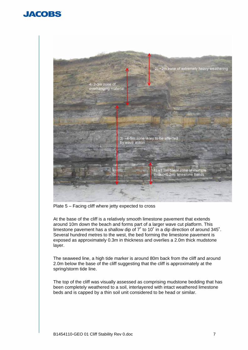
The base of the cliff was accessed by public footpath and a hand held GPS was used to verify the location. No direct measurements were taken of the orientation, steepness, dip and dip direction of bedding within the cliff face due to concerns about the possibility of rockfalls occurring from the cliff face. The cliff itself is approximately 7m to 8m in height, mainly vertical, aligned generally east to west. It is made up of interbedded Blue Lias mudstones and limestones exhibiting varying degrees of weathering. Plate 5 was taken at the point the jetty is expected to cross the cliff.
B1454110-GEO 01 Cliff Stability Rev 0.doc 7
Plate 5 – Facing cliff where jetty expected to cross At the base of the cliff is a relatively smooth limestone pavement that extends around 10m down the beach and forms part of a larger wave cut platform. This limestone pavement has a shallow dip of 7˚ to 10˚ in a dip direction of around 345˚. Several hundred metres to the west, the bed forming the limestone pavement is exposed as approximately 0.3m in thickness and overlies a 2.0m thick mudstone layer. The seaweed line, a high tide marker is around 80m back from the cliff and around 2.0m below the base of the cliff suggesting that the cliff is approximately at the spring/storm tide line. The top of the cliff was visually assessed as comprising mudstone bedding that has been completely weathered to a soil, interlayered with intact weathered limestone beds and is capped by a thin soil unit considered to be head or similar.

B1454110-GEO 01 Cliff Stability Rev 0.doc 8
3.4 Weathering Processes
The limestone beds control the weathering profile, protecting the mudstone whilst in-situ. A combination of tidal processes, freeze thaw and other weathering processes work on and around the rock. When a limestone block falls the mudstone is rapidly weathered into alignment with the next limestone face, this action then migrates up the cliff face. Where limestone bands are exposed on the beach or in the cliff section it occurs as a strong rock. The limestone fractures along bedding and joint planes with the blocks that are formed having dimensions approximately equal to the bed thickness. As erosional forces work them loose, these fractured rectangular blocks fall out of the cliff or are forced out of the pavement and are transported eastwards by tidal processes during which they become reduced in size by abrasion and other processes. The exposed mudstone varies between heavily and completely weathered, is weak to extremely weak, often fracturing on extremely close discontinuities. It is possible that some of the mudstone that is less weathered is calcareous as it is more homogeneous and more massive. 3.5 Weathering Profile
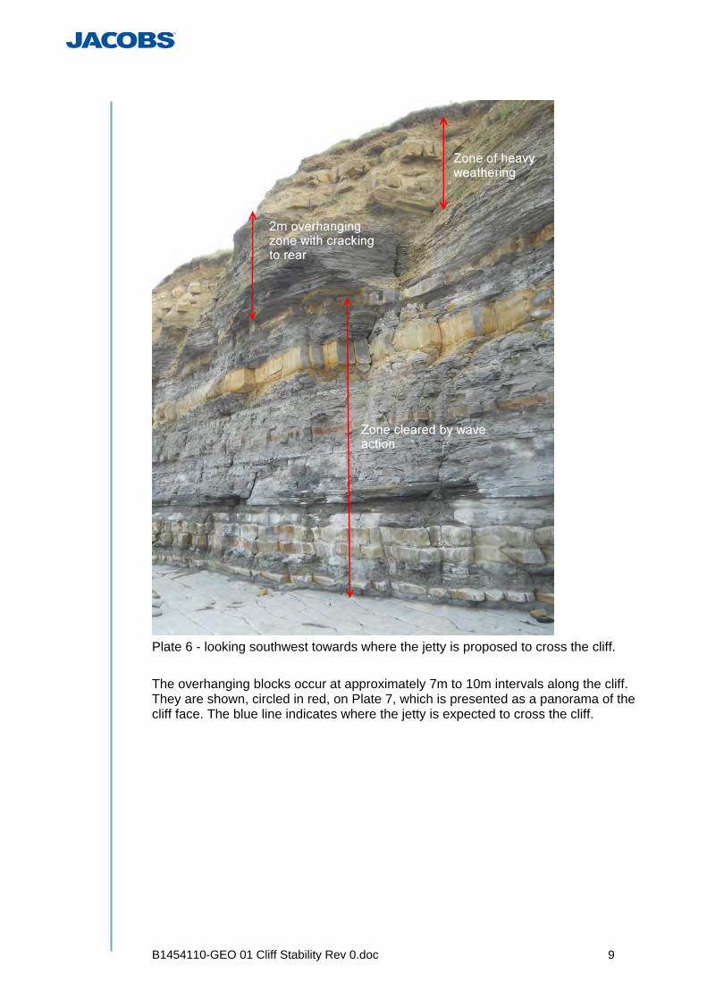
The base of the cliff (identified as 1 on Plate 5) is made up of several thick hard limestone bands which may offer some protection to the cliff toe at this location. The first four to five metres of the cliff face (identified as 3 on Plate 5) is generally horizontally bedded, this is the zone assumed to be affected by storm and wave action. Above this zone is an area of rock overhang (identified as 4 on Plate 5) that is approximately two to three metres high, which wave action is assumed not to reach. Cracks can be seen running behind these overhangs. The top two to three metres of the cliff (identified as 2 on Plate 5) is very heavily weathered with the mudstone completely weathered to a soil; where this is not supported by the vegetation at the top of the cliff it slopes up at approximately 45˚. Plate 6 was taken looking southwest towards where the jetty is proposed to cross the cliff. It shows the shallower profile of the uppermost weathered zone and the vertical face affected by wave action. It also shows some of the cracks present behind the overhanging zones which run for several metres vertically up the cliff face and can be up to 70mm wide.
B1454110-GEO 01 Cliff Stability Rev 0.doc 9
Plate 6 - looking southwest towards where the jetty is proposed to cross the cliff. The overhanging blocks occur at approximately 7m to 10m intervals along the cliff. They are shown, circled in red, on Plate 7, which is presented as a panorama of the cliff face. The blue line indicates where the jetty is expected to cross the cliff.

B1454110-GEO 01 Cliff Stability Rev 0.doc 10
Plate 7 - panorama taken across the cliff looking north showing overhanging blocks. 3.6 Stability and Potential Failure Mechanisms
The overhanging blocks identified in Plate 7 are around three metres to five metres in length, two metres to three metres deep and two metres to three metres in height with weathered material above and undercut beneath by wave action. If total failure occurred as a planar slide along a bedding plane with the rear crack acting as a release, the potential mass of blocks could be between 30 tonnes and 100 tonnes in weight. For this to occur the dip angle would need to be greater than the friction developed along the bedding plane. Small rockfalls from the western end of these overhanging blocks occur frequently, some large limestone blocks around 0.5m by 0.5m have fallen from the cliff very recently. Several small rockfalls occurred during the site visit. The shape of these overhangs appeared to be controlled by a failure plane running out from the cliff causing the cracks identified in Plate 6. Plate 8 shows a fault running along the bedding with a dip of around 5˚ in a direction 310˚ through the limestone pavement. This fault appears to have a throw of around 3-5cm to the north and appears to travel up the cliff, (the bag in the picture is approximately perpendicular to where the jetty would cross the cliff).
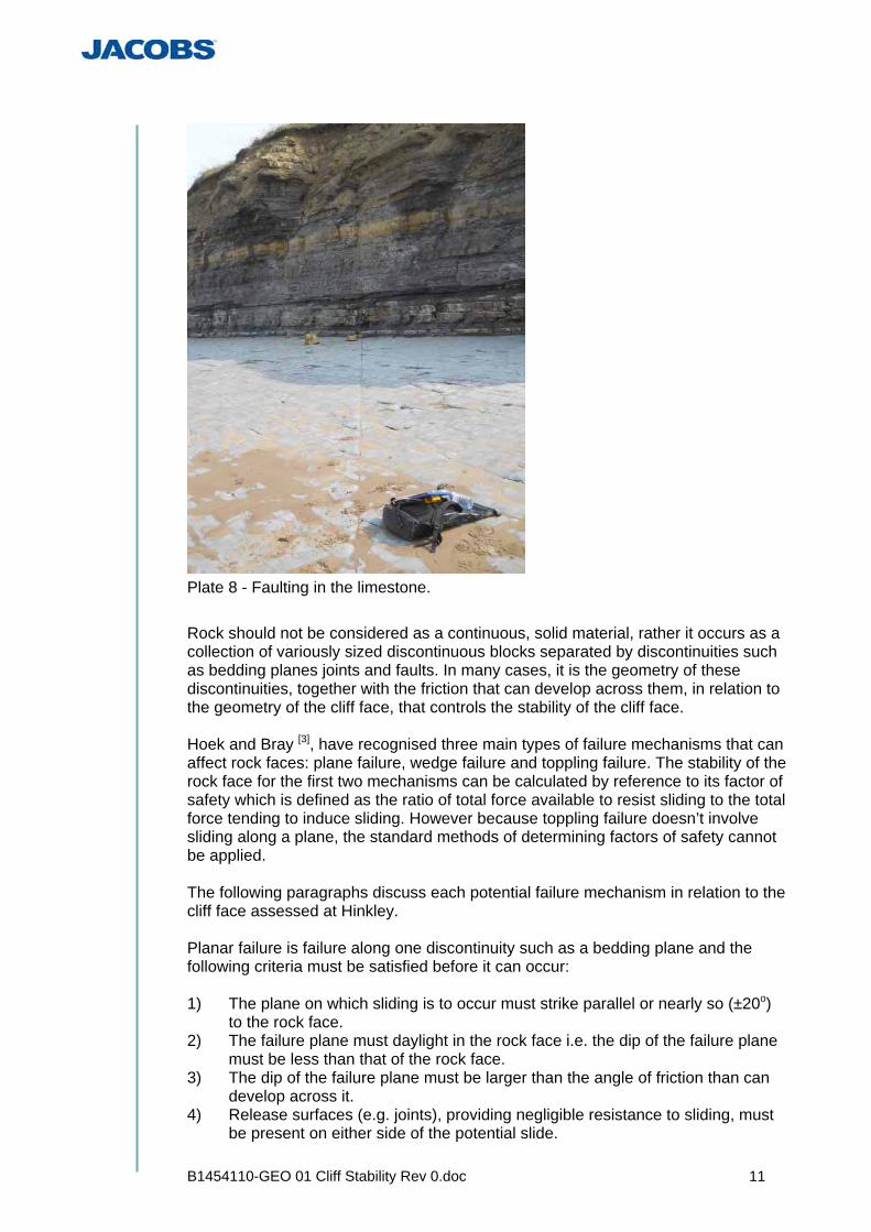
B1454110-GEO 01 Cliff Stability Rev 0.doc 11
Plate 8 - Faulting in the limestone. Rock should not be considered as a continuous, solid material, rather it occurs as a collection of variously sized discontinuous blocks separated by discontinuities such as bedding planes joints and faults. In many cases, it is the geometry of these discontinuities, together with the friction that can develop across them, in relation to the geometry of the cliff face, that controls the stability of the cliff face. Hoek and Bray [3], have recognised three main types of failure mechanisms that can affect rock faces: plane failure, wedge failure and toppling failure. The stability of the rock face for the first two mechanisms can be calculated by reference to its factor of safety which is defined as the ratio of total force available to resist sliding to the total force tending to induce sliding. However because toppling failure doesn’t involve sliding along a plane, the standard methods of determining factors of safety cannot be applied. The following paragraphs discuss each potential failure mechanism in relation to the cliff face assessed at Hinkley. Planar failure is failure along one discontinuity such as a bedding plane and the following criteria must be satisfied before it can occur: 1) The plane on which sliding is to occur must strike parallel or nearly so (±20o)
to the rock face. 2) The failure plane must daylight in the rock face i.e. the dip of the failure plane
must be less than that of the rock face. 3) The dip of the failure plane must be larger than the angle of friction than can
develop across it. 4) Release surfaces (e.g. joints), providing negligible resistance to sliding, must
be present on either side of the potential slide.
B1454110-GEO 01 Cliff Stability Rev 0.doc 12
At Hinkley, the potential failure planes would be the bedding planes separating the individual mudstone and limestone layers. The dip of these beds was assessed at a maximum of 10o during the cliff inspection with a generally east to west strike. The cliff face was assessed as mainly vertical during the site visit and therefore parts 1) and 2) of the failure criteria above are satisfied. Friction between the bedding planes is considered to be much higher than 10o and could possibly be higher than 30o and therefore part 3 of the above criteria is not satisfied. Friction could be reduced by heavy rainfall and water seepage along the bedding planes but it is considered unlikely that the reduction necessary to cause planar failure could be achieved. Even if the most steeply dipping failure plane is considered i.e. between a point 15m back from the top of cliff to the toe of the cliff, as shown in the geological model, it is considered unlikely that the dip of this potential plane would be steeper than the friction that could develop across it; especially as the shear strength of the limestone and mudstone layers would also have to be exceeded. The possibility of the cliff face at Hinkley failing by planar failure is therefore considered unlikely. Wedge failure can occur when: 1) Two discontinuities intersect forming a wedge 1) The line of intersection of these two continuous discontinuities is shallower
than the dip of the cliff face and daylights within it. 2) The trend of this line is approximately equal to the dip direction of the cliff. 3) The plunge of this line of intersection must be greater than the friction
developed across the discontinuities. At Hinkley, the two discontinuities could comprise bedding and a joint and although the line of intersection formed by these two discontinuities is likely to be shallower than the cliff face, the friction developed along the two surfaces is likely to be much greater than the plunge of the line of intersection. It is also considered unlikely that heavy rainfall could reduce friction to such an extent that failure could occur. Therefore, the possibility of the cliff face at Hinkley failing by wedge failure is considered unlikely. The third major mechanism is toppling failure which relies on the rotation of a column/block of rock about a fixed point. However, although blocks were seen to fall out of the cliff face, this mechanism is not considered feasible because of the shallow dip of the various beds. The retreat of the cliff face at Hinkley is considered cyclical in nature. 1) The cycle starts by erosion of the bottom part of the cliff within the zone of
wave action forming a wave cut notch and leading to the development of detritus immediately in front of the face.
2) This detritus is eventually removed and increased erosion occurs 3) The wave cut notch extends into and up the cliff face eventually causing a
large overhang to develop part way up the face above the zone of wave action.
4) A vertical or steeply dipping tension crack develops between the overhang and the main part of the cliff.

B1454110-GEO 01 Cliff Stability Rev 0.doc 13
5) Weathering processes including freeze thaw act upon the tension crack widening and deepening it
6) Failure under gravity of the overhang by sliding along the tension crack. In conclusion, erosion within the zone of wave action allows the failure process to start which is then propagated up the cliff face by small slab or block failures.
B1454110-GEO 01 Cliff Stability Rev 0.doc 14
4 Construction Implications
During the construction and lifetime of the jetty, which is expected to be around 10 years there are several processes that may well impact the cliff where the jetty passes over it. 4.1 Construction Traffic
The primary construction route will be from the land orthogonal to the cliff face, and from the sea, orthogonal to the cliff face. Construction traffic along the foreshore is to be kept to a minimum. A temporary access route for small construction plant to gain access to the foreshore may be constructed at the existing low point between the jetty and Hinkley Point A. If required, traffic movements on the foreshore will be restricted to a 15m strip at the base of the cliff. This will be addressed within the Contractor’s Method Statements. Similarly construction plant movements parallel to the top of the cliff will be minimised with inland routes used in preference to cliff top routes, addressed within the Contractor’s Method Statements. Vibration impact from trafficking of this plant could have an impact upon the stability of the cliff.. 4.2 Construction Process
It is proposed that the offshore piles will be driven through the superficial sea bed deposits and weathered rock strata to competent rock head level. A rock socket will then be drilled to a depth of some 6 – 8 m into competent rock, to a diameter a little larger than the pile. The socket will then be filled with concrete and the steel tubular pile will be installed into the wet concrete socket. The pile installation landward of the cliff will utilise a similar socket approach but the initial installation to rock head would be undertaken in a manner to mitigate potential impact to the cliff face The foreshore piles are expected to be constructed by boring through weathered / weaker strata and the underlying competent rock strata and then installed into a 6 m socket in the competent rock strata. The landside piles are planned to be installed through the superficial and weathered / weaker rock strata into a predrilled and concreted rock socket extending some 6 m into competent rock strata. It is anticipated that they will be required to penetrate approximately 6 m to 8 m because of the thick weathered zone observed, and the presence of a thicker mudstone layer in this area – hence the rock socket is anticipated to lie below the toe of cliff). These piles are to be installed in a manner which avoids impact driving of the pile through the superficial deposits and weathered / weaker rock strata. It is specified that a pre-drilled / cased hole will be formed in the upper strata and the pile then installed into the hole after which drilling and forming of the concreted rock socket will take place The loading of the piling rig may have an effect on the cliff stability. Vibrations generated by the piling/drilling equipment, may be transmitted into the cliff through the strong limestone layers and adversely impact its stability.

B1454110-GEO 01 Cliff Stability Rev 0.doc 15
The impact from the installation of the foreshore piles immediately in front of the cliff may have a greater impact due to their closer proximity to the face. 4.3 Demolition Process
It is planned that the jetty will be decommissioned and demolished once it is no longer required. Dependent upon the nature of this demolition process, which may include cutting, excavation and breaking of concrete, vibration impacts may occur which could significantly affect the adjacent cliff. 4.4 Operational Use
The jetty consists of a conveyor belt and roadway which will be utilised to transport many thousands of tonnes of aggregate. This could result in the development of continual vibration from a working conveyor with cyclic loadings from loaded trucks. The loading on the foreshore piles is unlikely to impact upon the cliff as the pile socket where the majority of the load will be taken will be several meters beneath the existing beach level in competent rock. The landside piles will also transfer its load through a socket into the deeper rock. The zone of influence of the pile will extend downwards in the form of a cone starting 6m to 8m below existing ground level, see the conceptual model in Appendix A where this is shown diagrammatically.

B1454110-GEO 01 Cliff Stability Rev 0.doc 16
5 Engineering Considerations
5.1 Existing Cliff Stability
The cliffs at present can be regarded as metastable; this means their Factor of Safety against collapse is close to unity. Small rockfalls occur almost continually along the cliff section with two noted during the few hours spent on site. However it is likely that large rockfalls would generally and predominantly occur during/immediately after an extreme weather event e.g heavy rainfall and/or high tidal events e.g. high spring or storm tides especially when they occur together. Additionally the repeated winter mechanism of freeze-thaw could also trigger a high volume failure. These extreme weather conditions would normally result in less pedestrian traffic along this section of the foreshore. 5.2 Construction Stability
The vibration impact from the repeated trafficking of construction plant could have an impact upon the stability of the cliff over the entire length used by this traffic. Vibrations generated by the piling equipment, even if bored piles are used may be transmitted into the cliff through the strong limestone layers and adversely impact its stability with the installation of the closer piles having a greater effect. The loading on the foreshore piles in front of the cliff is unlikely to impact upon the cliff as the pile socket, where the majority of the load will be taken, will be several metres beneath the existing foreshore into competent rock. The landside piles will also transfer their load through a socket into the deeper, more competant rock. The zone of influence of the pile will extend downwards in the form of a cone which will not extend to the cliff face. The future demolition process could also significantly affect the stability of the adjacent cliff face through trafficking of plant and vibrations developed by the demolition processes such as drilling, excavation etc 5.3 Ongoing Stability
Any zones exposed by rockfalls potentially triggered by activities associated with the jetty are likely to result in a fresher and more stable face. The removal of these localised unstable zones is not thought to enhance erosion in the long term. Although the effects of construction and demolition may have some impact on the cliff stability, the natural coastal erosion cycle will continue and is likely to eventually outstrip and remove all evidence of man’s influence on the site.

B1454110-GEO 01 Cliff Stability Rev 0.doc 17
6 References
1. EDF Energy Drawing Number: B1454110-C.01a-1002-REV B, Hinkley Point – Temporary Aggregate Jetty, General Layouts, Illustrative Site Long Section
2. British Geological Survey, 1980, 1:50,000 scale Weston-Super-Mare
geological map sheet number 279.
3. Institute of Mining and Metallurgy, 1981, E Hoek and J W Bray, Rock Slope Engineering,

Appendix A - Conceptual Geological Model

Hinkley Point C: Temporary Jetty Development, Cliff Stability Report, Rev 0 June 2011
Appendix D Excerpts from Amec Geological Survey

Geological Survey and Mapping
15122/TR/0011 Issue 02 - Final June 2009

Geological Survey and Mapping
EDF Access
AMEC
15122/TR/0011 v
Issue 02 - Final
EXECUTIVE SUMMARY
The western area of the cliff section adjacent to the EDF controlled land at Hinkley Point is
located within the ‘Blue Anchor to Lilstock’ Site of Special Scientific Interest (SSSI). The
SSSI designation is for the unique cliff stratigraphy, together with a geomorphological
designation for the exposed rock pavement. Natural England, the principal consultee for any
construction proposals that have the potential to impact a designated site, has expressed the
need to ensure that the unique cliff stratigraphy is not lost as a result of the construction of
foreshore infrastructure.
In order to accommodate foreshore construction proposals at Hinkley Point, it is necessary
to demonstrate that the same geological sequence that is observable and accessible at
Hinkley Point is replicated elsewhere along the coastal section which extends up to a
distance of approximately 10 km to the west, and that the replicated site is equally
accessible to the public.
AMEC were instructed by EDF to provide a Technical Specification document that outlined
the works required to produce a report for presentation to Natural England in respect of
foreshore construction proposals at Hinkley Point. AMEC provided EDF with the required
Technical Specification (AMEC Ref: 15011/TN/00018) and were subsequently instructed to
proceed with providing this geological survey and mapping report.
In accordance with Technical Specification 15011/TN/00018, the following tasks have been
undertaken. Firstly, the stratigraphic sequence at Hinkley Point has been determined; to
include the identification of geological units within the cliff section adjacent to and extending
west of the EDF controlled land (as required by Natural England). The stratigraphic
sequence at Hinkley Point has been quantified by a combination of literature review and field
mapping. Three key geological units were identified that enabled the complete sequence
and duplicate sequences to be accurately mapped. Secondly, a walkover of the cliff and
foreshore section between St. Audrie’s Bay and Lilstock was undertaken in order to
qualitatively identify appropriate candidate locations where the same stratigraphic sequence
(as determined at Hinkley Point) is exposed. Thirdly, the stratigraphic sequence of a cliff
section between St Audrie’s Bay and Lilstock was mapped, to include the identification of
geological units. Fourth, an appropriate evidence base has been presented that concludes
that the stratigraphic sequences observed at Hinkley Point are indeed replicated to the west,
and that they are equally accessible to the public.
This report demonstrates that the section to the west of Lilstock is a high quality duplicate of
the Hinkley Point geology. Moreover, it is argued that the duplicate section is a better
example than the Hinkley Point cliffs as the greater cliff height enables all of the units to be
observed within one discrete section. Lastly, it was qualitatively demonstrated that the
characteristics of the foreshore geomorphology at Hinkley Point can be observed elsewhere
within the SSSI to the west.
Geological Survey and Mapping
EDF Access
AMEC
15122/TR/0011 27
Issue 02 - Final
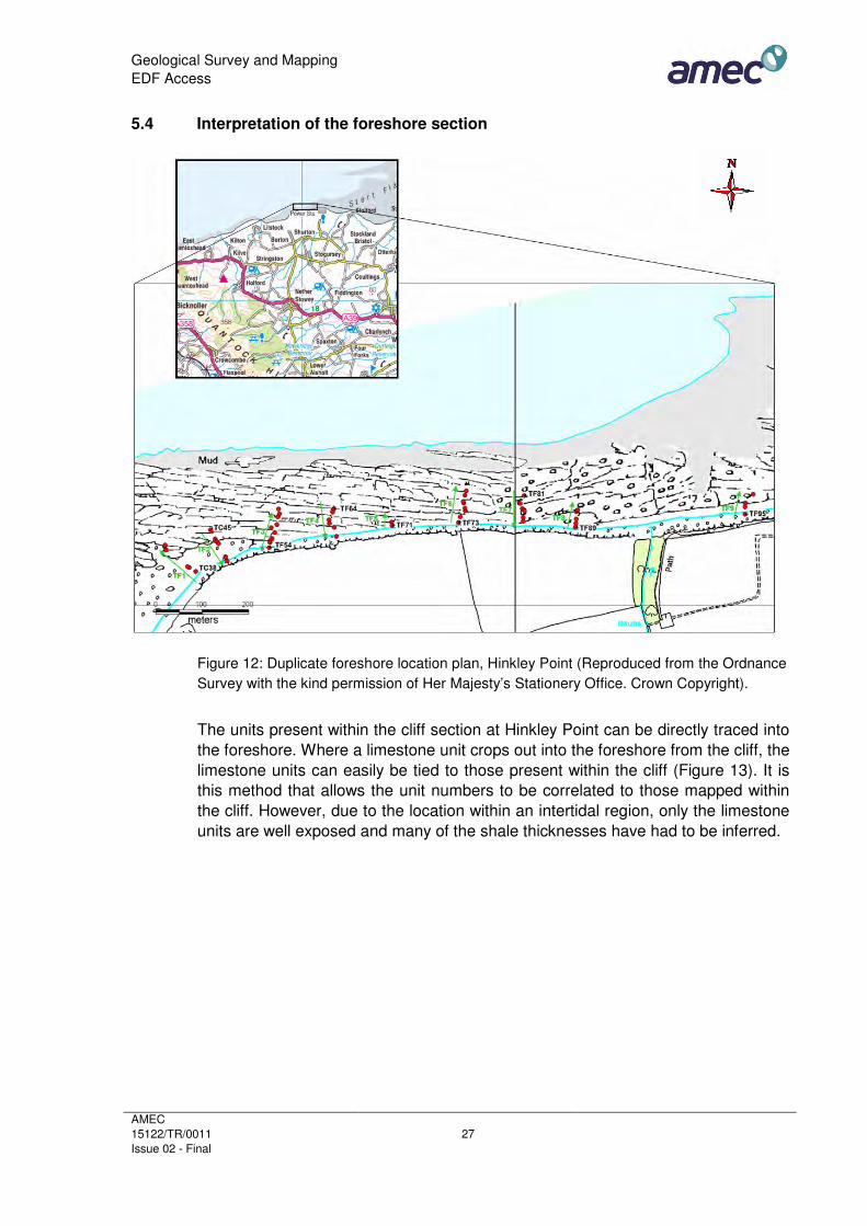
5.4 Interpretation of the foreshore section
Figure 12: Duplicate foreshore location plan, Hinkley Point (Reproduced from the Ordnance
Survey with the kind permission of Her Majesty’s Stationery Office. Crown Copyright).
The units present within the cliff section at Hinkley Point can be directly traced into
the foreshore. Where a limestone unit crops out into the foreshore from the cliff, the
limestone units can easily be tied to those present within the cliff (Figure 13). It is
this method that allows the unit numbers to be correlated to those mapped within
the cliff. However, due to the location within an intertidal region, only the limestone
units are well exposed and many of the shale thicknesses have had to be inferred.
Geological Survey and Mapping
EDF Access
AMEC
15122/TR/0011 28
Issue 02 - Final
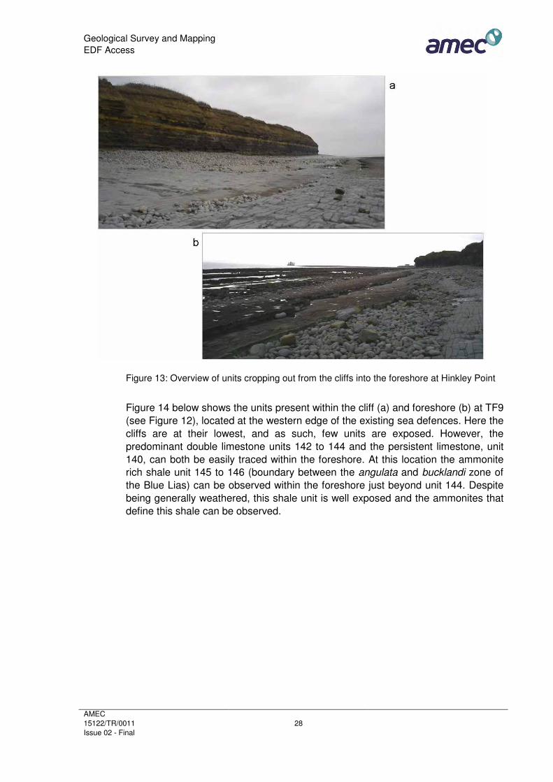
Figure 13: Overview of units cropping out from the cliffs into the foreshore at Hinkley Point
Figure 14 below shows the units present within the cliff (a) and foreshore (b) at TF9
(see Figure 12), located at the western edge of the existing sea defences. Here the
cliffs are at their lowest, and as such, few units are exposed. However, the
predominant double limestone units 142 to 144 and the persistent limestone, unit
140, can both be easily traced within the foreshore. At this location the ammonite
rich shale unit 145 to 146 (boundary between the angulata and bucklandi zone of
the Blue Lias) can be observed within the foreshore just beyond unit 144. Despite
being generally weathered, this shale unit is well exposed and the ammonites that
define this shale can be observed.

Geological Survey and Mapping
EDF Access
AMEC
15122/TR/0011 29
Issue 02 - Final
Figure 14: TF9, the foreshore near the existing sea defences at Hinkley Point
TF3 (Figure 15) is located beyond the western edge of the EDF controlled land.
Here, the limestone unit 109 crops out directly into the foreshore. Traversing out
from the cliff at this point, all of the limestone units present within the cliff can be
observed. Despite being extensively eroded, the majority of the limestones retain
their specific features (for example, shelly fragments within unit 114), as observed
within the cliff. The shales at this point are poorly exposed and are covered in a
veneer of mud, boulders and seaweed making access to the exposed limestone
units difficult and potentially hazardous.

Geological Survey and Mapping
EDF Access
AMEC
15122/TR/0011 30
Issue 02 - Final
Figure 15: TF3, the foreshore beyond the western boundary of the EDF controlled land at
Hinkley Point
Figure 16 below shows the cliff section (a) and foreshore (b) at the western edge of
the EDF controlled land. Unit 114 crops out into the foreshore and can be traced
for approximately 10 m before it becomes completely covered by sand, boulders
and pooled water. The less persistent units (for example, the lenticular unit 128)
are present but poorly exposed and are hard to trace through the boulder fields.
Extensive weathering of these units means that dip measurements were
unobtainable.
Figure 16: TF4, the foreshore adjacent to EDF controlled land at Hinkley Point

APPENDIX B
HINKLEY POINT SECTION LOGS AND PHOTOGRAPHS

TC18
Plate 28: TC18 – the exposure continues with little observable change from TC17. Units above 130 are observable within the weathered material at the top of the cliff Plate 29: Log for TC18 (overleaf)
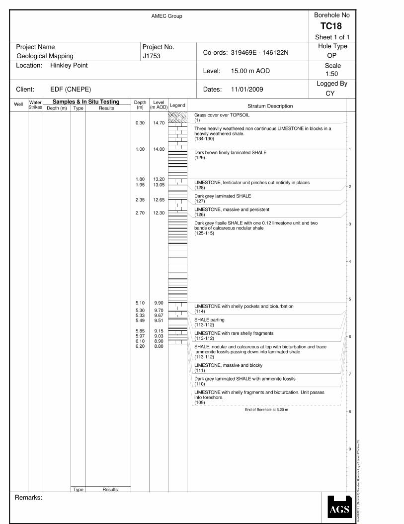
Well WaterStrikes Depth (m)
Depth LevelLegend(m) (m AOD) Stratum Description
Project Name
Location:
Client: Dates:
Level:
Co-ords:Project No.
Borehole No
Scale
Logged By
Remarks:
Hole Type
Geological Mapping
Hinkley Point
EDF (CNEPE)
Type
Type
Samples & In Situ TestingResults
Results
J1753
AMEC Group
319469E - 146122N
15.00 m AOD
11/01/2009CY
TC18
OP
Ho
leB
AS
E 3
.1 (
Bld
41
4.8
) S
tan
da
rd B
ore
ho
le L
og
v2
da
ted
27
th N
ov 0
3
0.30
1.00
1.80
1.95
2.35
2.70
5.10
5.305.335.49
5.855.976.106.20
14.70
14.00
13.20
13.05
12.65
12.30
9.90
9.709.679.51
9.159.038.908.80
Grass cover over TOPSOIL(1)
Three heavily weathered non continuous LIMESTONE in blocks in aheavily weathered shale.(134-130)
Dark brown finely laminated SHALE(129)
LIMESTONE, lenticular unit pinches out entirely in places(128)
Dark grey laminated SHALE(127)
LIMESTONE, massive and persistent(126)
Dark grey fissile SHALE with one 0.12 limestone unit and twobands of calcareous nodular shale(125-115)
LIMESTONE with shelly pockets and bioturbation(114)
SHALE parting(113-112)
LIMESTONE with rare shelly fragments(113-112)
SHALE, nodular and calcareous at top with bioturbation and trace ammonite fossils passing down into laminated shale(113-112)
LIMESTONE, massive and blocky(111)
Dark grey laminated SHALE with ammonite fossils(110)
LIMESTONE with shelly fragments and bioturbation. Unit passesinto foreshore.(109)
End of Borehole at 6.20 m
1
2
3
4
5
6
7
8
9
1:50
Sheet 1 of 1


