32D04NE2011 2.18746 MCGARRY 010 Quantec IP Inc. P.O Box 580,101 King Street Porcupine, ON RON 1 CO Phone (705) 235-2166 Fax (705) 235-2255 Quantec IP Incorporated Geophysical Survey Logistical Report Qyantec GRADIENT-REALSECTION TDJPINDUCED POLARIZATION SURVEY at the LARDER-BEAR LAKES PROPERTIES, LARDER LAKE, ONT 9 on behalf ofStANDREWGOLDFIELDS LTD. HIPHIP HIP HIP OIP K Blackshaw JM Legault G Kallfa April, 1998 QIP P220 2.1874 6
Transcript
32D04NE2011 2.18746 MCGARRY 010
Quantec IP Inc. P.O Box 580,101 King Street Porcupine, ON RON 1 CO Phone (705) 235-2166 Fax (705) 235-2255
Quantec IP Incorporated
Geophysical Survey Logistical Report
Qyantec
GRADIENT-REALSECTION TDJPINDUCED POLARIZATION SURVEY at the LARDER-BEAR LAKES PROPERTIES, LARDER LAKE, ONT9 on behalf ofStANDREWGOLDFIELDS LTD.
HIP HIP HIP HIP OIP K Blackshaw JM Legault G Kallfa April, 1998 QIP P220
2.1874 6
QIP P 220 l IHIII HI 11 HI Hill IJIl HI) Ill Hill Hill Hill Hill Hill H!!! Hill Hill Illlll III Illl StAndrew Goldfiekte Ltd.Larder-Bear Lakes ON RSIP
QIPP220 StAndrew Goldfields Ltd. Larder-Bear Lakes ON RSIP
* QIP Project No:
* Project Name:
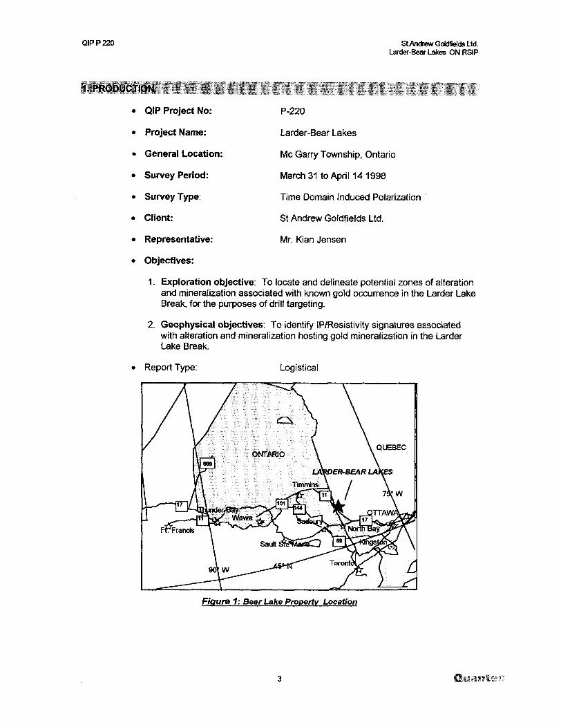
* General Location:
* Survey Period:
* Survey Type:
* Client:
* Representative:
* Objectives:
P-220
Larder-Bear Lakes
Me 0?arry Township, Ontario
March 31 to ApriM4 1998
Time Domain Induced Polarization
St Andrew Goldfields Ltd.
Mr. Kian Jensen
1. Exploration objective: To locate and delineate potential zones of alteration and mineralization associated with known gold occurrence in the Larder Lake Break, for the purposes of drill targeting.
2. Geophysical objectives: To identify IP/Resistivity signatures associated with alteration and mineralization hosting gold mineralization in the Larder Lake Break.
Report Type: Logistical
Figure 1: Bear Lake Property Location
QIPP220 StAndrew GoMfiekfe Ltd. Larder-Bear Lakes ON RSIP
2.1 LOCATION
2.2 ACCESS
Township or District:
* Province or State:
* Country:
* Nearest Settlement:
* Nearest Highway:
* Base of Operations:
* Mode of Access:
McGarry Township l Mcvittie (Bear Lake) McGarry Township (Larder Lake)
Ontario
Canada
Virginiatown Ontario
Ontario highway 66
Kirkland Lake Ontario
From Kirkland Lake by 4 wheel drive truck approximately 20 kilometers East on highway 66; then by snowmobile on Bear Lake and Larder Lake grid accessible from Virginia town public dock.
2.3 SURVEY GRID
* Coordinate Reference System:
* Line Direction:
* Line Separation:
* Station Interval:
Local cut and picket survey grids
N600E for Bear Lake gridLarder Lake grid
1 00 meters.
20 meters
QIP P 220 StAndrew GoWfiekfe Ltd. Larder-Bear Lakes ON RSIP
3.1 GENERALITIES
* Survey Dates:
* Survey Period:
* Mobilization Days:
* Survey Days:
* Weather Days:
* Down Days:
* Total km Surveyed:
3.2 PERSONNEL
* Project Supervisor's):
* Field Assistants):
3.3 SPECIFICATIONS
* Array:
* AB (Tx dipole spacing):
* MN (Rx dipole spacing):
* Sampling Interval:
* Total Gradient AB Blocks:
* Total RealSections:
March 31 st to April 14th , 1998
15 days
1 day
13.5 days
1 day
None
7.46 km (Bear Lake gird) 8.46 km (Larder Lake grid)
Kevin Blackshaw, Owen Sound, ON
Paul Cassidy, South Porcupine ON Richard Chasse, Kirkland Lake ON Robin Ranger, South Porcupine ON Helene Rivest, Geophysicist, Porcupine, ON Kevin McKenzie, Nova Scotia David Easttcott, Thunder Bay, ON Eric Hotvedt. Ramore, ON Ludvig Kapllani, Toronto ,ON
Gradient (see also Figure 2 )
1550 to 3000 meters
20 metres (Bear Lake grid) 40 metres (Larder Lake grid)
20 meters
2 blocks (Bear Lake grid) 2 blocks (Larder Lake grid)
* Approximate Anal Coverage: 0.36 km2 (Bear Lake grid)0.48 krri2 (Larder Lake grid)
QIP P 220 StAndrew GoWfielcls Ltd. Larder-Bear Lakes ON RSIP
GRADIENT ARRAY
WIN = length PrP2 (6 x P,-P2 Spread)
GRADIENT ARRAY COVERAGE AREA
Figure 2 Gradient Array Layout
3.4 SURVEY COVERAGE:
1. Reconnaissance:
2. Detail follow-up:
6.2 km on Larder 5.2 km on Bear Lake
3.6 km on Larder Lake 2.26 km on Bear Lake
LINE | MIN EXTENTLL.O
LL.1WL.L2WL.L.3WLL4W
Total (Larder Lake)B.L.3SB.L2SB.L1S
Total (Bear Lake)
SOONSOON520N
520NE540NE
1000E820E
1000W
MAX EXTENT700S700S700S760S760S
900W980W500E
Length (m)1200M1200M1220M1280M1300M6200
1900M1800M1500M5200
Table l: Reconnaissance Survey Coverage
QIP P 220 StAndrewGoldfieldsLtd. Larder-Bear Lakes ON RSIP
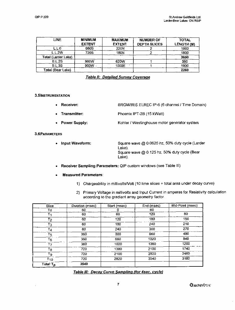
Receiver Sampling Parameters: QIP custom windows (see Table III)
Measured Parameters:
1 ) Chargeability in millivolts/Volt (10 time slices + total area under decay curve)
2) Primary Voltage in millivolts and Input Current in amperes for Resistivity calculation according to the gradient array geometry factor.
SliceTdT1
T2
TST4
TST6
T7
T8
T9
T10
Total Tp
Duration (msec)6060
60
60
60
360
360
360
720
720
720
3540
Start (msec)0
60120180240300
660
1020
1380
2100
2820
End (msec)60120
180
240
300
660
1020
1380
2100
2820
3540
Mid-Point (msec)
80
150
210
270
480
840
1200
1740
2460
3180
Table III: Decay Curve Sampling ffor4sec. cycle)
QIP P 220 SLAndrew Goldfields Ltd. Larder-Bear Lakes ON RSIP
SliceTdTIT2T3T4T5T6T7T8T9T, 0
Total Tp
Duration (msec)4020303030
180180180360360360
1760
Start (msec)0
60120180240300660
102013802100
2820
End (msec)40
120180240300660
10201380210028203540
Mid-Point (msec)
80150210270450840
1200174024603180
Table II: Decay Curve Samplin (for 2 sec, cycle)
3.7MEASUREMENT ACCURACY AND REPEATABILITY
* Chargeability.
* Resistivity:
generally less than 0.5 mV/V but acceptable to+LOmV/V.
less than 50Xo cumulative error from Primary voltage and Input current measurements.
QIPP220 St .Andrew Gokffiekfe Ltd. Larder-Bear Lakes ON RSIP
3.8 DATA PRESENTATION
Maps:
Reconnaissance Coverage:
"Realsection" Detail follow-up:
Digital:
Raw data:
Processed data:
using the following format:
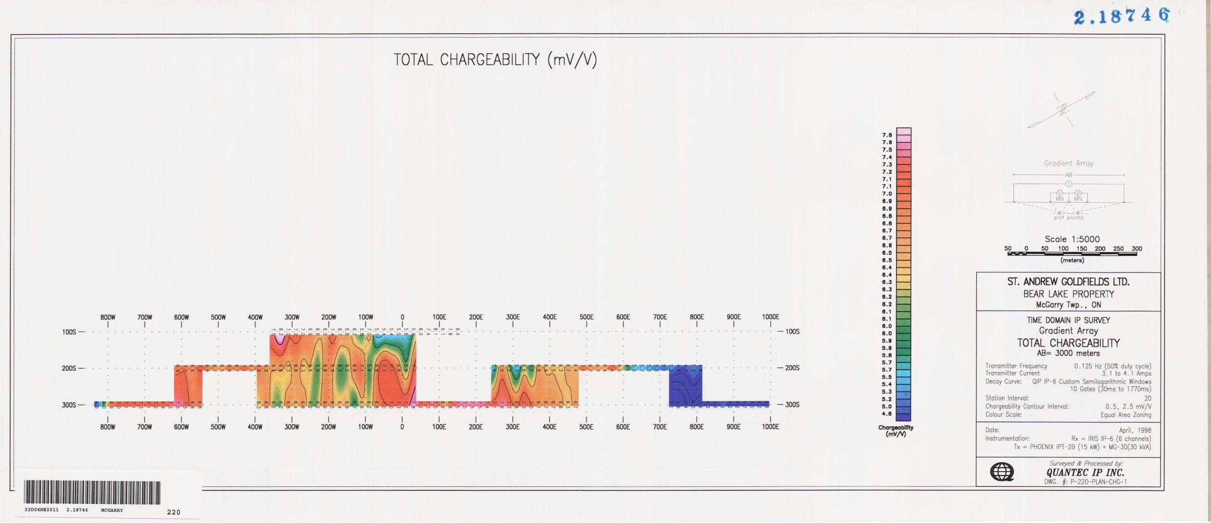
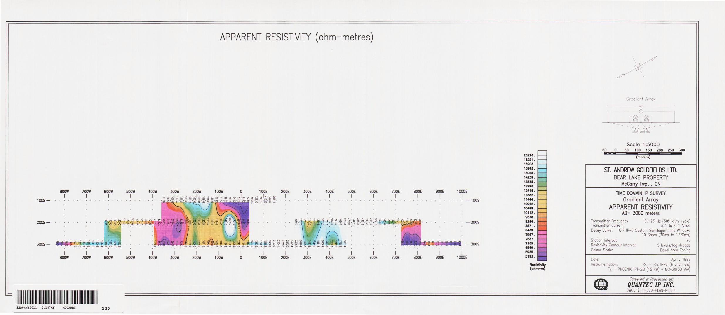
Posted and contoured plan maps of Total Chargeability and Resistivityat a scale of 1:5000 meters
Posted and contoured depth section maps of Total Chargeability and Resistivity at a scale of 1:5000 meters
IP-6 digital dump file (See also Appendix C).
Geosoft .XYZ format.
Column 1 = Line (X Position), in metersColumn 2 = Station (Y Position), in metersColumn 3 = Total Chargeability, in m V/VColumn 4 = Apparent Resistivity, in O-mColumn ^ = TDIP Spectral Estimates, derived using IPREDC
i ',
Kevin Blackshaw Operations Manager
RESPECTFULLY SUBMITTED
QUANTEC KING.
Jean M. Legault, P.Eng. (ON) Senior Geophysicist
Gene Wallfa Senior Geophysicist
Porcupine, ON April 1998
QIPP220 StAndrew GoWfidds Ltd. Larder-Bear Lakes ON RSIP
STATEMENT OF QUALIFICATIONS:
l, Jean M. Legault, declare that:
1. l am a consulting geophysicist with residence in South Porcupine, Ontario and am presently employed in this capacity with Quantec IP Inc. of Waterdown, Ontario.
2. l obtained a Bachelor's Degree, with Honors, in Applied Science (B.A.Se.), Geological Engineering (Geophysics Option), from Queen's University at Kingston, Ontario, in Spring 1982.
3. l am a registered professional engineer (# 047032), with license to practice in the Province of Ontario.
4. l have practiced my profession continuously since May, 1982, in North-America, South-America and North-Africa.
5. l am a member of the Society of Engineers of Ontario, the Northern Prospectors Association, the Prospectors and Developers Association of Canada, and the Society of Exploration Geophysicists.
6. l have no interest, nor do l expect to receive any interest in the properties or securities of St Andrew Goldfields Ltd.
7. l .oversaw the construction of the report and plots. The statements made in this report represent my professional opinion based on my consideration of the information available to me at the time of writing this report.
Porcupine, Ontario April, 1998
Jean M. Legault; P.Eng. Chief Geophysicist Dir. Technical Services Quantec Group
QIPP220 St Andrew GoWfiekfe Ltd. Larder-Bear Lakes ONRSIP
STATEMENT OF QUALIFICATIONS:
l, Gene Kallfa, declare that:
1. l am presently employed as geophysicist with Quantec IP Inc. of Waterdown, Ontario.
2. l obtained a M.D. in Geophysics, from Polytechnic University at Tirana, Albania, in February 1987.
3. l have practiced my profession continuously since May, 1987, in Albania and Canada.
4. l have no interest, nor do l expect to receive any interest in the properties or securities of St. Andrew Goldfields Ltd.
1. l am the technical writer for this report; l constructed this report and generated plots to the best of my ability with my current level of understanding.
Porcupine, Ontario April, 1998
illfaSenior Geophysicist - QTS Quantec IP
QIPP220 StAndrew Gokffiekfe Ud. Larder-Bear Lakes ON RSIP
PRODUCTION SUMMARY:
CUENTPROJEC
TSURVEY
DATE
31 -Mar-98
1 -Apr-98
2-Apr-98
3-Apr-98
4-Apr-98
5-Apr-98
6-Apr-98
7-Apr-98
8-Apr-98
9-Apr-98
10-Apr-98
11 -Apr-98
12-Apr-98
ST. Andrew GoldfiekJs Ud.P-220 Larder-Bear Lakes
Gradient "RealsectiotT IP Survey
DESCRIPTION
1 crew attempts to recover equipment from Pangea (too flooded)Mobilize to Kirkland Lake. 2nd crew grid orientation and access.
Weather - day (heavy rains)
Established AB 2800m on L 200W @ 1350S to H20N (Larder Lake)Lake electrodes preparation
Locate Tx site 1 km south of Hwy 66 .difficult due to wet conditions.Data noisy due to low signal improve AB location for increased current.
Low VP still, enhance current electrodes (more salt and rods).Due to low signal unable to measure with 20 m MN, read with40 m MN with 20 m station intervalData quality greatly improved
IP Survey
TotalIP SurveyEstablished AB 21 00m on L 200W @ 1 0OOS to 1 1 0ON
Total
IP Survey
Established AB 1550m on L 200W @ 1000S to 550N2nd crew demob from Kirkland after dinner
Total
Pickup AB wire and Tx setup from Larder Lake Grid.
Established AB 3000m on L 300S @ 1500 W to 1500E (Bear Lake).Augured hole for electrodes on lines 1 S.2S & 3S.
IP Survey
Total
IP SurveyCanoe is required to get on to the ice.
Total
Established AB 2500m on L 3+OOS at 1300E to 1240WIP Survey
Battery test: Grounding resistance: Memory capacity: Data transfer
31 cm x 21 cm x 21 cm6 kg with dry cells7.8 kg with rechargeable bat.-200C to 70*0(-AQ"C to 700C with optional screen heater)(-400C to 700C)6 x 1.5 V dry cells (100 hr. @ 200C) or2 x 6 V NiCad rechargeable (in series) (50 hr. @ 200C) or1 x 12 V external610Mohmup to 1000 volts10 V maximum on each dipole15V maximum sum over eh. 2 to 66 automatic 10 V with linear drift correction up to 1 mV/s50 to 60 Hz powertine rejections100 dB common mode rejection (for Rs= 0)automatic stacking1 jiV after stackingQ.3% typically; maximum 1 over wholetemperature rangeup to 10 windows; 3 preset window specs .plus fullyprogrammable sampling.10 ms10 ms, minimum 40 |iV0.1 mV/Vtypically Q.6%. maximum 20Xo of reading 1mVA/forVp^OmVmanual and automatic before each measurement0.1 to467kohm2505 records, 1 dipole/recordserial link @ 300 to 19200 baud
QIPP220 StAndrewGoMfiekteUd.Larder-Bear Lakes ON RSIP
IRIS IP 6 Dump File Format
* IP 6 (V9.1)*
#77 Jirf 1 1980 11:57dipole 1 trigger 1 domain Time T wave Programmable wind. Grad. RCTGL array
QIPP220 StAndrew GoWfields Ltd. Larder-Bear Lakes ON RSIP
INSTRUMENT SPECIFICATIONS:
Phoenix IP Transmitter Model IPT-2B
Power Sources:
Output Voltage:
Output Power
Maximum Current:
Ammeter Ranges:
Meter Display:
Current regulation:
Output waveform:
Output waveform IPT-2B option:
Operating Temperature:
Frequency Stability:
Transient Protection:
Thermal Protection:
Dimensions:
Weight-
Shipping Weight:
Phoenix MG-19 (10KVA, 120V, 3 phase, 400 Hz) motor generator (30KVA, 120V, 3 phase) motor generator Phoenix MG-1,2 or 3 can also be used, but will generate Vi the voltage
To 1400V in four ranges of resp. 250-375V, 420-630V, 650-975V, 935- 1400V. Voltage is continuously variable 207o from each nominal step value.
Maximum continuous output power is 10KW. Absolute maximum output power is 15KW.
15 Amps
30m A, 100m A, 1A, 3A, 10A and 30A full scale.
A meter function switch selects the display of current level, regulation status, input frequency, output voltage, control battery voltage or line voltage
The change in output current is less than D.2% for a 1007o change in input voltage or electrode impedance. Regulation is achieved by feedback tothe alternator of the motor generator unit.
Either DC, single frequency, two frequencies simultaneously, or time domain (500Xo duty cycle). Frequencies of 0.078, 0.156, 0.313,1.25,2.5 and 5.0 Hz are standard, whereas 0.062,0.125, 0.25,1.0,2.0 and 4.0 Hz are optionally available. The simultaneous transmission mode has 0.313 and 5.0 Hz asstandard, whereas 0.156 and 2.5 Hz are optional.
9 frequencies in binary progression: 1/16 -1/32 -1/16 -1/8 -1/4 -1/2 -1 2 and 4, with variable duty cyde. Selectable to one of four values: 0.25, 0.5, 0.75, and 1.NOTE: Duty cyde = 1 is the operation equal to the standard frequency domain cycling, i.e. Full On, except for a 50m sec. gap at each half cycle.
-40"C to *600C
1 0Xo from -400C to *600C is standard. A precision time base is optionally available for coherent detection and phase IP measurements.
Current is turned off automatically if it exceeds 150"Xo full scale or is less than 507o full scale.
Unit is fan-forced cooled. Thermostat turns transmitter off at 650C andtums back on at 55"C internal temperature.
46 x 46 x 32 cm (18 x 18 x 13 in)
45kg
56kg
QIPPZ20 StAndrew GoldfieWs Ltd. Larder-Bear Lakes ON RSIP
THEORETICAL BASIS
The "RealSection" survey design uses multiple gradient arrays - with variable depths of investigation controlled by successive changes in array size/geometry. The method of data acquisition and the "RealSection" presentation are based on the specifications developed by Dr. Perparim Alikaj, of the Polytechnic University of Tirana, Albania, over the course of 10 years of application. This technique has been further developed for application in Canada during the past four years, in association with Mr. Dennis Morrison, president of Quantec IP Inc.
The Gradient Array measurements are unique in that they best represent a bulk average of the surrounding physical properties within a relatively focused sphere of influence, roughly equal to the width of the receiver dipole, penetrating vertically downward from surface to great depths. These depth of penetration and lateral resolution characteristics are showcased when presented in plan, however through the use of multiple-spaced and focused arrays, the advantages of the gradient array are further highlighted when the IP/Resistivity data are fully developed in cross- section, using RealSections.
The resistivity is among the most variable of all geophysical parameters, with a range exceeding 106 . Because most minerals are fundamentally insulators, with the exception of massive accumulations of metallic and submetallic ores (electronic conductors) which are rare occurrences, the resistivity of rocks depends primarily on their porosity, permeability and particularly the salinity of fluids contained (ionic conduction), according to Archie's Law. In contrast, the chargeability responds to the presence of polarizeable minerals (metals, submetallic sulphides and oxides, and graphite), in amounts as minute as parts per hundred. Both the quantity of individual chargeable grains present and their distribution with in subsurface current flow paths are significant in controlling the level of response. The relationship of chargeability to metallic content is straightforward, and the influence of mineral distribution can be understood in geologic terms by considering two similar, hypothetical volumes of rock in which fractures constitute the primary current flow paths. In one, sulphides occur predominantly along fracture surfaces. In the second, the same volume percent of sulphides are disseminated throughout the rock. The second example will, in general, have significantly lower intrinsic chargeability.
y -l x is
x - a x is
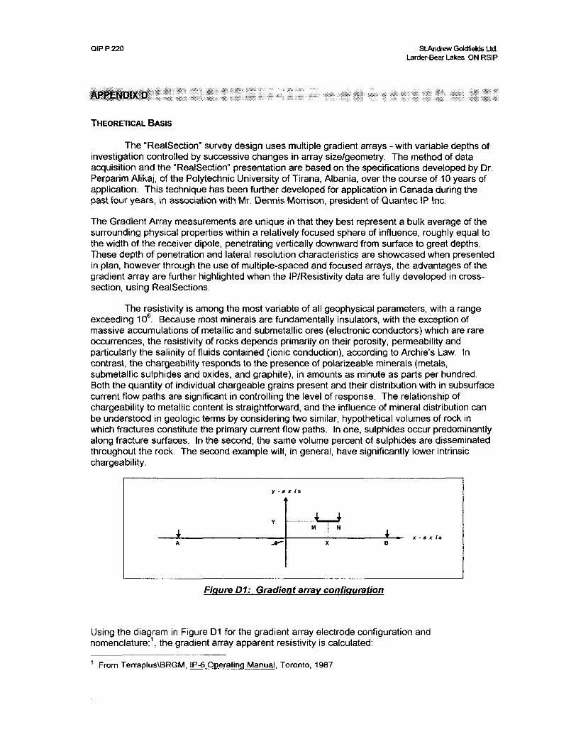
Figure D1: Gradient array configuration
Using the diagram in Figure D1 for the gradient array electrode configuration and nomenclature: 1 , the gradient array apparent resistivity is calculated:
1 From Terraplus\BRGM, IP-6 Operating Manual. Toronto, 1987.
QIPP220 StAndrew Gotctfields Ltd. Larder-Bear Lakes ON RSIP
where: the origin O is selected at the center of AB the geometric parameters are in addition ^oa = AB/2 and b s MN/2 X is the abscissa of the mid-point of MN (positive or negative) Y is the ordinate of the mid-point of MN (positive or negative)
Gradient Array Apparent Resistivity:VP
pa = K — ohm - metres
where: K = (AM'1 -AN'1 -BM'1 +BN'1
AM =
= ^|(x-b-a)2 +y 2
Using the diagram in Figure D2 for the Total Chargeability:
Measured Voltage Line
positive
negative
One half of Transmit Cycle
"Off Time"^—————————————^.
"On Time" t (0)
Figure D2 The measurement of the time-domain IP effect
the total apparent chargeability is given by:
QIPP220 StAn*ewGoldfieldsUd.Larder-Bear Lakes ON RSIP
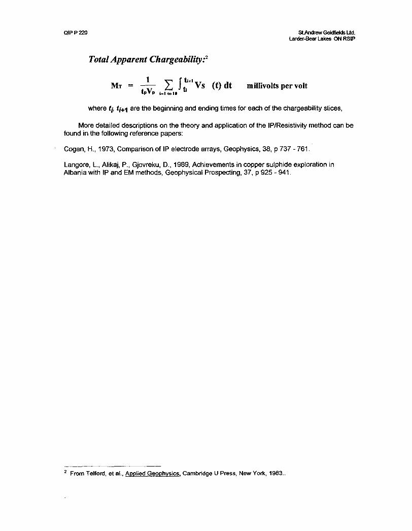
Total Apparent Chargeability:2
Mr ~ —— X L V1 Vs (t)dt millivolts per volt tpVp 1,1 to 10
where f/, t/^-j are the beginning and ending times for each of the chargeability slices,
More detailed descriptions on the theory and application of the IP/Resistivity method can be found in the following reference papers:
Cogan, H., 1973, Comparison of IP electrode arrays, Geophysics, 38, p 737 - 761.
Langore, L., Alikaj, P., Gjovreku, D., 1989, Achievements in copper sulphide exploration in Albania with IP and EM methods, Geophysical Prospecting, 37, p 925 - 941.
2 From Telford, et al., Applied Geophysics. Cambridge U Press, New York, 1983..
INTERPRETATION AND EVALUATION OF THE QUANTEC- ST. ANDREW L P. SURVEY' OVER. THE WATER PORTION OF THE SALO- BECKETT BEAR LAKE PROPERTY .AND CONCLUSIONS, IMPLICATIONS .AND RECOMMENDATIONS FOE. FUTURE EXPLORATION.
INTRODUCTION
OBJECTIVES
THE EXPLORATION OBJECTIVE OF THIS SURVEY WAS TO LOCATEAND DELINEATE POTENTIAL ZONES OF ALTERATION AM) MINERALIZATION FOR, THE PURPOSE OF DRILL TARGETING POTENTIAL GOLD ORE. THE GEOPHYSICALOBJECTIVE WAS TO IDENTIFY i P. RRSISTMTY SI (^NATURES ASSOCIATED WITH ALTERATION AM) M^KR AT.iZA Q O 5 HOS'TfNG (-K)ij) MMESALJZATIO'Ni' fN'TBE ARFA
GENERAL GEOLOGY AND '?.flNES.ALIZAT[ON
THIS .PROPERTY IS LOCATED IN THE AKETBI VOLCANIC BELT' OF THE SUPERIOR PROVINCE OF THE CANADIAN SHIELD. THE .ABITIBI VOLCANIC BELT EYTENDS FOR NEARLY 3?0 'MLES IN A. WEST-K\ST DIRECTION' 'FROM IIMMINS TO ^^IBOUGAMAU. IT IS HOST TO A VARIETY OF PRECIOUS AND BASE METAL DEPOSITS IN THE ITMMINS, &TRJKLAND LAKE, NOEANDA, VALDO.R, MAITAGA34I AMD CHIBOf/GAMAU :Wvi'l]vRj CAMPS.
THE A BOTBI VOLCANIC BELT IS COMPOSED OF A COMPLEXASSEMBLAGE OF INTERBEDDED VOLCANIC AND SEDIMENTARY ROCKS INTRUDED BY A VARIETY OF INTRUSIVES FROM ULTRA BASIC TO GRANITIC IN COMPOSITION. THE ROCKS ARE ARCHAEN IN AGE AND HAVE BEEN METAMORPHOSED TO THE GREENSCHIST FACIES. NUMEROUS LATE PRECAMBRIAN DIABASE DYKES CUT FORMATIONS OF THE BELT. THE ROCKS GENERALLY STRIKE EAST-WEST, HAVE A VERTICAL DIP AND ARE HIGHLY FOLDED AND FAULTED. GEOLOGICAL INTERPRETATION OF THE ABniBI VOLCANIC BELT IS COMPLICATED BY BOTH THE WIDE SCATTERING OF OUTCROPS AND 'THE COMPLEX STRUCTURAL RELATIONSHIPS.
PROPERTY GEOLOGY
THE PROPERTY IS UNDERLAIN BY AN EAST TRENDING UNIT OF INTERMEDIATE TO MAFIC METAVOLCANIC ROCKS COMPRISED OF ANDESrnCAND BASALTIC LAVAS. THE INTERMEDIATE TO MAFIC VOLCANICS .ARE IN MAJOR CONTACT WITH META-SEDIMENTS, JUST NORTH OF BEAR LAKE. IHEMETASEDBffiNTS .ARE COMPRISED MAINLY OF CONGLOMERATE, CONTAINING NARROW NORTH-NORTH-WEST 'TRENDING BANDS OF FINE GRAINED, MAINLY GREYWACKE, THE METASEDIMENTARY BAND SURROUNDS A WEST-SOUTH WEST TO WEST STRIKING UNIT OF AIJSAIIC METAVOLCANICS, (TRACHYTE AND PORPHYRITIC TRACHYTE) UNDERLYING THE EAST -NORTH PART OF THE PROPERTY. VARYING SEE BODIES OF FELSIC INTRUSIVE ROCKS (SYENITE AND SYEWnC PQRPHRld EXTENSIVELY UNDERLIE TEE PROPERTY .AREA..
STRUCTURE
THE PROPERTY LIES IN AN AREA OF EXTENSIVE AND COMPLEX STRUCTURAL DEFORMATION. A MAJOR DEFORMATION ZONE IN A. SYNCLINAL FOLD ASSOCIATED WITH THE LARDER LAKE BREAK STRIKES WEST SOUTH- WEST A.CROSS THE SOUTH END OF THIS PROPERTY AND TWO PARALLEL STRIKING FAULT ZONES, PARALLEL TO THE LARDER LAKE BREAK,END .AT BEAR LAKE IN THE SOUTH AREAS OF THIS PROPERTY. THE BROAD SPECTACLE- LAKE KERR-ADDISON ANTICLINORIUM TRENDS EAST SOUTH -FAST ACROSS TfflS PROPERTY AND LS CROSS CUT BY MINOR FOLDS. THE .AXIS OF TfflS .ANTOINE CROSSES THE PROPERTY E-W AT THE SOUTH END OF THE ST. ANDREW BLAND AND ON CLAIM L- 1187099. A. MAJOR NORTH-NORTH -EAST TRENDING FAULT IS OFFSET ON THE NORTH WEST SIDE OF THE ISLAND AT THE .AXIS OF THE ANTICLINE AND PROBABLY IS A SPLAY OFF THE: LARDER. LAKE BREAK. A STRATIGRAPHIC VOLCANIC- SEDIMENTARY CONTACT CROSSES THE LOWER PART EAST-WEST OS CLAM L-l 187100 AND AGAIN ACROSS THE SOUTHERN PART OF THE ISLAND TRENDING NORTH- WEST NEAR THE AXIS OF THE ANTICLINE AND MAY ACTUALLY REPRESENT THE NOSE OF A CROSS CUTTING FOID. ACROSS THE! NORTH PART OF THE PROPERTY THE BEAR CREEK SHEAR ZONE TRENDS EAST-SOUTH EAST TOWARD THE KERR MINE AND JUNCTIONS WITH A NORTH SOUTH FAULT AT THE EXTREME NORTH- EAST END OF BEAR. LAKE:. SEDIMENTS AND VOLCANICS., PERHAPS BOTH HNOJEVB AND TEMSKAMMG AGE MAY UNDERLIE TfflS AREA. OF TRANSITION, HEAVILY INTERCALATED.
MINER. AUZA.TI0N IN AREA.
MOST EmORATION HAS BEEN GENERALLY IN THEAREA. OF MAJOR FACIES CHANGE THAT HAS BEEN RELATIVELY ACCESSIBLE ON THE SOOTH FLANK OF THE: ANTICLINE. IBIS PROPERTY STRADDLES THIS ANTICLINE .AIL KNOWN MINERAL OCCURENCES THAT HAVE BEEN OOID PRODUCERS OR NEAR PRODUCERS ARE ALONG, OR NEAR THIS MAJOR FACIES CHANGE, SO THIS IS A PROVEN AREA FOR PRECIOUS METALS. THE GREAT KERR MINE, ONCE THE LEADING GOLD PRODUCER. IN NORTH .AMERICA, IN EXCESS OF 12 MILLION OUNCES OF GOLD, IS LOCATED SOME 7500* TO THE EAST. THE CHEMENIS MINE OF NFX LTD IS TEED ON TO THIS PROPERTY TO 'THE WEST. SEVERAL GOLD OCCURENCES HAVE BEEN DISCOVERED IN OR NEAR THE CONTACTS OF THE FELSIC INTRUSIVE ROCKS WITHIN 2300' OF THE PROPERTY. THE ARMISTICE MINE TO THE EAST BFrTWEEN THE KERR AND CHEMINIS MINES WILL BECOME A. PRODUCER SOON.
IP. SURVEY RESULTS
.AN .ANALYSIS OF THE GEOPHYSICAL DATA,GEOMETRICAL AND PHYSICAL PARAMETERS OF THE ANOMALOUS ZONES, POSSIBLE CAUSES OF BACKGROUND AND ANOMALOUS VALUES, KNOWN AND SPECULATED CAUSES OF ANAMALOUS VALUES AND THEIR SIGNIFICANCE.
5,
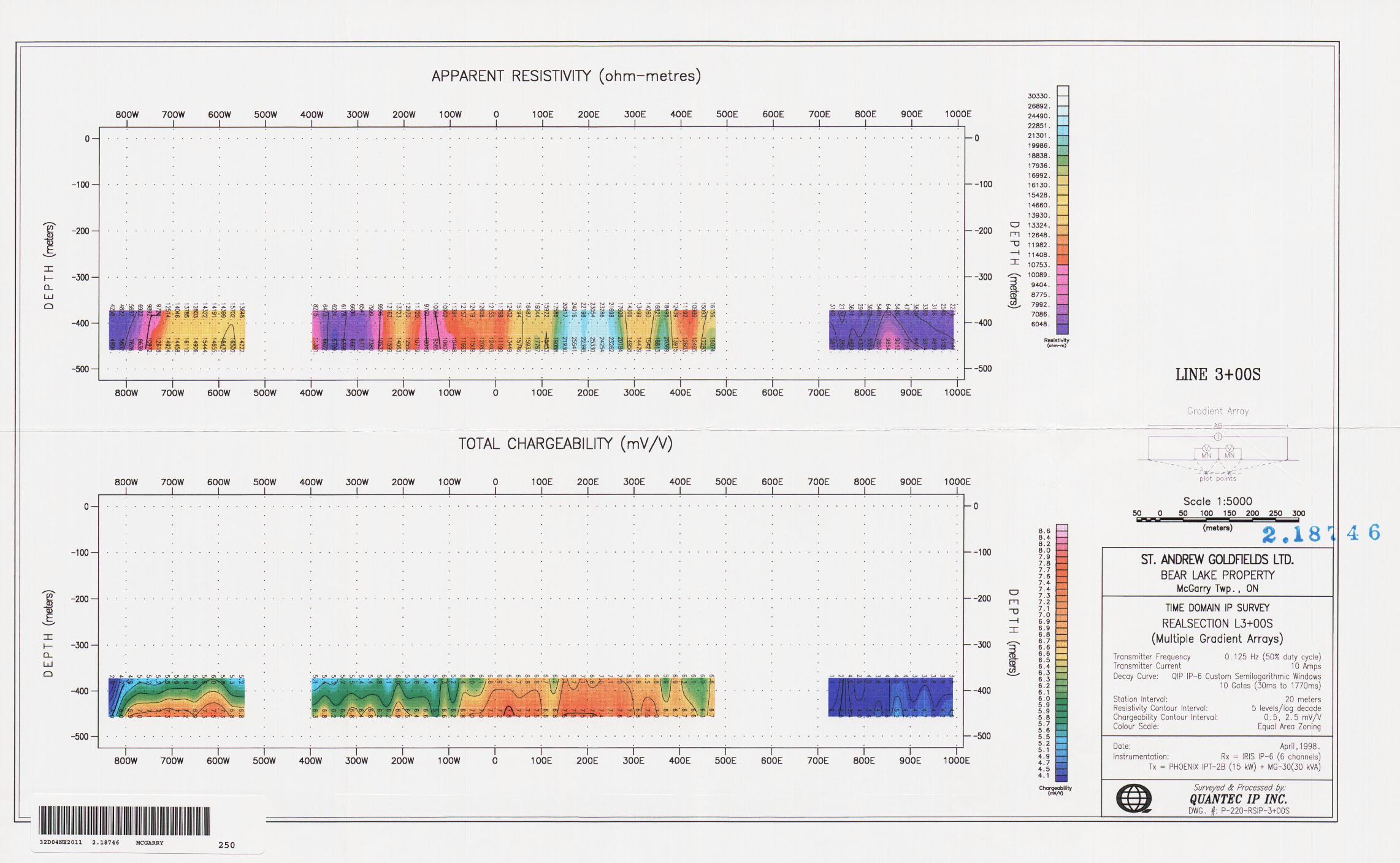
L-300S AB
(1) A MAJOR ANOMALOUS AREA OF HIGH CHARGEABILITY IS INDICATED BETWEEN LINE 20 E AND 400 W, PERSISTING TO LINE 100 S. FROM 20 W TO 80 W VERY HIGH RESISTIVITY IS COINCIDENT WITH THIS MAIN AREA. OF fflGH CHARGEBIUTY, BETWEEN 20 E 80 W AND ALSO PERSISTS ALMOST TO LINE 100 S. THIS .ANOMALOUS SECTION IS INTERPRETED .AS MINIMIZATION IN SYENITE PORPHRY ALTERED HfflNERALEEDAND SILICIFIED ANT) EXTENSIVE STOCK WORK MINERALIZED QUARTZ' VEINING. THE; LOWER RESISTIVELY FROM 40 E TO 200 W AND COINCIDENT fflGH TO MODERATE CHARGEBIUTY INDICATES .AND IS INTERPRETED AS SHEARING TRENDING E-W AND N-W INTRUDED BY ALTERED CARBONATEED MINERALIZED MAFIC VOLCANICS AND CROSSING A. .FAULT TRENDING N E AND OTHER SHEARING IN A MINOR FOID TRENDING N-S AT THE MAIN CONTACT OF ALTERED,CAHBONAT1ZED AND SILICIFIED, MINERALIZED BASALTS .AND HIGHLY ALTERED, SILICIFIED AND MINERALIZED SYENITE PORPHRY WITH EXTENSIVE QUARTZ WINING.
THE REAL SECTION IP. RESULTS AND DEFINITION SHOW THAT THIS MAJOR ANOMALOUS .AREA (ANOMALY) PERSISTS TO THE MAXIMUM ESTABLISHED SURVEY DEPTH AND PROBABLY DEEPER ALIHOUGH IT SEEMS AT 400 M DEFIH TO BE DIPPING TO THE EAST AND NARROWING SOMEWHAT IN THE PROCESS. THE: MAIN AREA OF HIGH CHARGEABILITY AND HIGH RESISTIVELY AS OUTLINED IN THE FOREGOING CONSTITUTES A fflGH PRIORITY GOLD TARGET WITH ENORMOUS TONNAGE POTENTIAL.
(2) THE N E TRENDING FAULT IS FURTHER INDICATED BETWEEN LINE 400 W AND 340 W AND IS OFFSET BY MORE SHEARING AND SYENITE, QUARTZ PORPHRY INTRUSION. THE HIGH CHARGEBlUrY BETWEEN 540 W AND 630 W AND BETWEEN LINES ZOO S AND 300 S AND COINCIDENT HIGH RESISTIVITY INDICATE A PROBABLE FAULT JUNCTION AND AN E W TRENDING CONDUCTIVE ANOMALY ALONG A. SHEAR ZONE AT THE CONTACT OF ALTEREDSIUCMED AND CARBQNATEED SEDIMENT'S AND BASALTS, MINERALIZED INTRUDED BY HIGHLY ALTERED, SEJCIFIED AND MINERALIZED SYENITE PORPHRY. THE CONDUCTIVITY INDUCTIVE, PERSISTS WESTWARD ON STRIKE WTTH THE WINCHESTER-LARDER SHOWING (VALUES AS HIGH AS 10 OZ PER TON AU IN SILICIFIED MINERALIZED SYENITE.) THE CHARGEBHITY AND MODERATE RESISTIVITY OF THIS ANOMALOUS AREA IS VERIFIED BY REAL SECTION RESULTS TO PERSIST TO THE DESIGNATED SURVEY DEPTH AND PROBABLY DEEPER AND REAL SECTION L P. INDICATES FOLDED MAFIC VOLCANICS , CARBONATJZED MINERALIZED SILICIFIED IN CONTACT WITH ALTERED SYENITE AND QUARTZ PORPHRY UNITS IN EXTENSIVE SHEARING, WITH MINERALIZED QUARTZ VENING.
(3) TO THE EAST HIGH CHMGEBEITY AND SOME COINCIDENT HIGH RESISTIVITY PERSISTS ALONG WHAT CAN BE MmWRETED AS A. VOLCANIC--SEDIMENTRY CONTACT FROM 40 E TO 240 E WHERE AGAIN HIGH CHARGEBEJTYAND HIGH RESISTIVITY ARE COINCIDENT BETWEEN 240 E TO 470 E. TWO CONDUCTORS, ANOMALIES CAN BE INTERPRETED BETWEEN 240 E TO 350 E, ONE TRENDING NW AND THE OTHER NE, THE LATTER ALONG A. FAULT PERSISTING TO 740 E WHERE IT IS OFFSET AND JUNCTIONS WITH A MAJOR FAULT STRUCTURE THE CONDUCTIVE INDUCTIVE, ANOMALIES CAN' BOTH BE INTERPRETED AS ALTERATION CARBONATION, SILICIFICATION QUARTZ VEIN1NG MINERALIZATION AT THE SHEARED CONTACT OF VOLCANICS .AND SEDIMENTS INTRUDED.BY SILICIFIED SYENITE PORPHRY. REA!., SECTION IP. INDICATES THAT THESE ANOMALOUS ZONES PERSIST TO THE DESIGNATED DEPTH OF THE SURVEY, OVER. 400 METRES. THESE ZONES REPRESENT HIGH PRIORITY GOLD TARGETS.
7,
(4) TD THE EAST AT 740 E THE FAULT JUNCTION IN AN AREA OF LOW (MM.GEBILTTY .AND LOW RESISTIVITY PERSISTS ON REAL LP. TO 'TEE DESIGNATED SURVEY DEPTH INDICATING A PREDOMINANCE OF SEDIMENTS IN A NARROWING MAJOR STRUCTURE TRENDING N E, JUNCTIONING WITH AN E W STRUCTURE, WHICH IS DEEP INFO VOLCANICS AT DEPTH AND MAY REPRESENT A SPLAY OFF THE LARDER LAKE BREAK
IN GENERAL TOE REAL SECTION LP. RESULTS INDICATE ALL ZONES ARE PLUNGING S-E AND THE MAIN CONDUCTIVE AREA IS IN THE CENTER OF A. MAJOR FOLD TRENDING S E. DIPS VARY FR.OM 80 TO 90 OR ALMOST VERTICAL
ALL TARGET'S OUTLINED ARE IMPORTANT AND ARE INDICATIONS OF GREAT GOLD TONNAGE POTENTIAL
CONCLUSIONS
THE IP. SURVEY HAS BEEN SUCCESSFUL IN DEFINING POSSIBLE GOLD BEARING ZONES AS EVIDENCED BY HIGH CHARGEKOJTIES AND HIGH RESISTIVITIES.
WE HAVE; BEEN PROVIDED WITH DEEP GEOLOGIC INFORMATION BASED ON VERTICAL AND LATERAL CONTRASTS IN RESISTIVITY WE HAVE ALSO BEEN ABIE TO DELINEATE VARIOUS ALTERATION, STRUCTURAL AND ITIHOLOGIC FEATURES BOTH AT SURFACE AND AT DEPTH AND ARE: .ABLE TO DEFINE THEIR WIDTH DEPTH AND GEOMETRICS, WITH STRONG VERTICAL RESOLUTION. THE FREQUENCY USED HAS BEEN ABIE TO ELIMINATE THE "LAKE EFFECT." CHMGEBJUITES HERE SHOW A CLEAR TREND AS DO THE RESISTIVITIES WHICH CONSTITUTE A. TRACEABLE TREND. 'THERE HAS OBVIOUSLY BEEN SOME MASKING BY OVERBURDEN IN SOME AREAS OBSCURING BEDROCK RESPONSE AS IN TOE NORTH EAST OF THE LAKE. THE POTENTIAL ELECTRODE SPACING MN HAS BEEN KEPT AT 20 METRES (RX DIPOLE SPACING) AND HAS GIVEN AS HIGH A RESOLUTION AS POSSIBLE AND HAS RETAINED RESOLUTION.
WE; HA.VE GREAT DEPTH POTENTIAL HEBE IN THIS AREA. WE HAVE ESTABLISHED THE MORE SILICEOUS UNITS THAT HAVE A HIGHER PERCENTAGE OF SULPHIDES AND THE RESISTIVITY HAS REMAINED FAIRLY CONSTANT AT DEPTH ALTHOUGHSOME CHARGBEIOTY HAS BEEN LOST WHICH IS NORMAL. THE ANOMALIES ESTABLISHED CO-RELATE WELL WITH AIRBORNE CONDUCTORS PICKED UP IN THE "UNPUBLISHED SURVEY" BY DIGHEM FOR KERR, ADDISON MINES IN THE VIRGTNIA.TOWN .AREA. .ALTHOUGH THE AIRBORNE SURVEY LINES OF FLIGHT MIGHT HAVE BEEN BETTER ORIENTED IN OUR CASE THE RESISTIVITY IN THIS AIRBORNE SURVEY ALSO CO-RELATES WELL AND EMPHASIZES THE CONTAC.rS .AM) EXTENSIVE .ALTERATION .AND SYENITIC, MAFIC INTRUSION IN THE .AREA. THE HORIZONTAL, E M WORK DONE BY EDOMAR .AND FILED AS .ASSESSMENT WORK AS WELL AS THE FERDEBER AIRBORNE SURVEY FILED AS ASSESSMENT WORK ALSO CO-RELATE WELL WITH TfflS SURVEY.
WE HAVE AN .AREA. HERE OF COMPLEX FOLDING FAULTING, FRACTURING AND INTRUSION. THE ROCKS UNDERLYING TfflS PROPERTY ARE HIGHLY DEFORMED.WE: HAVE A FAULT WHICH MAY BE A SPLAY OFF THE LARDER LAKE BREAK. WE; HAVE EVIDENCE OF MANY CONTACTS AS WELL AS EXTENSIVE SHEARING. WE HAVE; EVIDENCE OF HEAVY DUTY ALTERATION, SILICIFICATION AND CARBONATIZATION. WE HAVE ESTABLISHED CONDUCTIVE RESISTIVE ANOMALIES WHICH REPRESENT HIGH PRIORITY GOLD TARGETS. THE ANOMALIES OF INTEREST REPRESENT ZONES OF SHEARING .AND MINERALIZATION.
IMPLICATIONS
FAVORABLE LOCATIONS FOR. GOLD IN THE AREA ARE FAULT SHEAR ZONES AND INTERSECTION OF FAULTS AND SHEAR ZONES NEAR METASEDIMENTARY, METAVOLCANIC FELSIC INTRUSIVE CONTACTS OR CONDUCTORS. THE, AREA IS
MAGNETIC SIGNATURES BY ALTERATION PROCESSES OF A MAJOR HYDROTHERMAL SYSTEM ORE ZONES OCCUR. IN CLOSE PROXIMITY TO OR IN PORPHORI'IIC LAVA, WHICH PREDOMINATES HERE.
GOLD CAN OCCUR ON BOTH SIDES OR FLANKS OF TEE SYENITE INTRUSIVES AND IN THE INTRUSIONS THEMSELVES. THE FLOW ORE BODES AT THE KERR .ARE MORE COHERENT WITH DEPTH. THE SHEAR ZONES TO THE WEST ARE 50'- lOtf WIDE RELATED SOMEWHAT NORTH SOUTH TO MINOR FOLDS CROSSING THE MAIN SPECTACLE -LAKE, KERR-ADDISON ANTICLINE WHICH BISECTS THIS LAKE AREA E-W. EXTENSIVE MJNEF.ALfZA.nON HAS BEEN ENCOUNTERED ON THE FLANKS OF THIS MAJOR ANTICLINAL STRUCTURE, THE PROPERTY STRADDLES BOTH FLANKS. BLACKWELL LAKE TO THE WEST HAS A HEAVY DUTY CARBONATE ZONE ON STRIKE (700 LONG AND 40 WIDE.) WITH THE MAIN IP ANOMALY. THERE IS A SHEAR ZONE 73'WIDE AND SOO'LONG IN THE; MAFIC VOLCANICS IN SYENITE PORPHRY BETWEEN BLACKWELL AND BEAR LAKE DIRECTLY ON STRIKE TO THE WEST THIS SHEAR WAS 5 "/o TO 13 "/o PYRITE AND LS CHLORITIZED. IT HAS BEE NOTED AS A. SHEARED IRON FORMATION. THE WINCHESTER LARDER SHOWING ON STRIKEWITH 'THE: SECOND i p ANOMALY is IN A SHEAR OF HIGHLY ALTERED ANDSILICIFIED SYENITE PORPHRY 100* WIDE - 500* LONG WITH ASSAYS UP TO 10 OZ AU PER TON.
THE GEOTEM SURVEY DOES NOT SHOW CONDUCTORS IN THIS AREA. BUT THE MAGNETICS INDICATE THE NOSE OF A MAGNETIC FOID WHICH MAY BE KJNOJEVIS VOLCANICS. THE: KERR AND CHESTERVELLE PROPERTIES TO THE EAST HAVE A SIMULAR FOLD NOSE WITH ORE BODIES IN THE NOSE OR ON ITS HANKS. MINOR FOLDS MAY EVEN CONTAIN VOLCANOGENIC DEPOSITS LIKE UPPER BEAVER. ON THE NORTH FLANK OF THE SPECTACLE LAKE-KERR ADDISON ANTICLINE IF KINOJEVIS BASALT'S UNDERLIE IN THIS AREA INTRUDED BY QUARTZ AND SYENITE PORPHRY, THE MAGNESIUM BASALTS WHICH ALTERNATE WITH THE THOELUnC REPRESENT THE SAME KOMATHTIC BASALTS AS AT THE; HOYLE POND WHICH ARE AS IMPORTANT' .AS THE ULTRAMAFIC KOMATDTES AS A SOURCE OF GOLD. THETEMKKAMMG CONGLOMERATES AND GREYWACKE ARE UNCOMFORMABLE WITH THE KOSfOJEVIS VOLCANICS BUT AT THIS FACIES CHANGE ARE FOUND MOST OF THE', GOLD ORE BODIES.
16,
WE MUST REMEMBER .ALSO TEAT .ANOMALIES CAUSED BY MINERAJJZATION IN SHEAR ZONES MIGHT OVERPRINT MANY DISSEMINATED SULPHIDE CONCENTRATIONS IN CLOSE PROXIMITY WHICH COULD CONTRIBUTE TO INCREASED ORE POTENTIAL ALSO NORTH EAST 'TRENDING ZONES WHICH MAY BEHT SPLAYS OFF THE MAIN BREAKS ARE RECOGNIZED AS BEING OF GREAT SIGNIFICANCE. WEAKER IP TARGETS BEING SUPPRESSED BY OVERBURDEN OR MASKED BY SHEARING SHOULD NOT BE OVERLOOKED.
RECOMMENDATIONS
ONE DRILL HOLE TO TEST THE POTENTIAL ECONOMICSIGNIFICANCE OF THE MAIN ANOMALY IS RECOMMENDED BEFORE SPRING BREAK UP AS DRILLING WILL HAVE BEEN DONE ON THE LAKE AND BECAUSE OF POOR ICE CONDITIONS A ICE PLATFORM WILL HAVE TO BE BUILT UP AND A WOOD PLATFORM ICED INTO THIS PLATFORM FOR DRILL SUPPORT. BASED ON TEE RESULTS OF TEIS DRILL HOIJE A "FENCE' PROGRAM OF CROSS SECTION DRILLING CONTROLLED USING TRQPARI TESTS IN THE AREA OF THE MAIN IP ANOMALY MAY BE FEASIBLE IN ORDER TO DEFINE THE POTENTIAL PARALLEL ZONES IN CO-RELATION WITH THE IP SURVEY.
RESPECTFULLY SUBMITTED
ARVO J. SALO
/: ^ ,.
E TWP.j ** S \ f * ' f* * f M
N |' -r , ^ -s. f \f/ S X ^
v x- x ^A-*~f' x /
v^uv-r", __*r*3f * -. —:
- - - -' 7, X ^ N ^ ^i/
v ' - . . -" ' mf-
f -s r -* ^ Nx /
' \
Group Sketch of claims listed on Part A.Sketch or plan of the mining claim(s) must show the corner posts, witness posts, andline posts and the distances between the posts in metres.
Include topographic features such as lakes, rivers, creeks, ponds, etc. and developments such as hydro lines, highways, railways, pipelines, buildings, etc.
Refer to sample sketch on Part C.
Magnetic Declination Used.
Scale:
l" r: ! 73ZO X
J- - - -l,- --
1/85529 /"85530
a* MIT*.Declaration of Assessment Work Performed on Mining Land
Mining Act, Subsection 66(2) and 66(3), R.S.0.1990
Transaction Number (ollice use)
Assessment Files Research Imaging
bsections 65(2) and 66(3) of the Mining Act. Under section 8 of the Mining Act, this writ work and correspond with the mining land holder. Questions about this collection nent and Mines, 3rd Floor, 933 Ramsey Lake Road, Sudbury, Ontario, P3E 6B5.
32D04NE2011 2.18746 MCGARRY 900
Instructions: - For work performed on Crown Lands before recording a claim, use form 0240. - Please type or print in ink.
1. Recorded holder(s) (Attach a list if necessary)Name Client Number
2SL3) S , 3~ ' COLWCLeST
Te,ephone Number
Fax Number
Client NumberQ g
Telephone Number^ ̂ ̂
Fax Number
2. Tyge of work performed: Check (vQ and report on only ONE of the following groups for this declaration.
m^XGeotechnical: prospecting, surveys, n Physical: drilling stripping, n Rehabilitationli" accavc anH vunrV iinrlor co/Minn -IR fronc\ LI tronr.hinn anH accnriatoH accawc LIassays and work under section 18 (regs) trenching and associated assaysWork T Office Use
Commodity
Total S Value of Work Claimed
DatasWortc From 3 f Performed Day Month
Cf fr| Year
To
Global Positioning System Data (if available)
j ̂ Jf *? g JDay | Month | Yaar
NTS Reference
T Mining Division V *
M or G-Plan Number Resident GeologistDistrict V , r 4^ (d H/i . /l Jr'^V
Please remember to: - obtain a work permit from the Ministry of Natural Resources as required;- provide proper notice to surface rights holders before starting work;- complete and attach a Statement of Costs, form 0212;
, t - provide a map showing contiguous mining lands that are linked for assigning work;- include two copies of your technical report.
3. Person or companies who prepared the technical report (Attach a list if necessary)Name
5 FaxNumber-2:2. r-f"
Name Telephone Number
Address Fax Number
Name Telephone Number
Address Fax Number
2.1874y-/ /r ^ ^y ' (Print N*
rtli n
this Declaration of Assessment Work having caused the work to be performed or witnessed the same during or after its completion and, to the best of my knowledge, tto annexed report is true. ___
Signature of Date
Fax Numberlumb /tS
0241 RECEIVED
AUG 1 8 13SS
GEOSCIENCE ASSESSMENT ____ OfFiC?.
5. Work lo ue i^curJed and distributed. Worx can only oe assigned iu uanns mm QICland where work was performed, at the time work was performed. A map showing the contiguous link must acqpmpanythis'
Mining Claim Number. Or If work WM done on other eligible mining land, show In this
column the location number Indicated on the claim map.
Number of Claim Units. For othermining land, list hectares.
ValiMOfwork performed on this claim or other mining land.
Value of work applied to this claim.
Value of work assigned to other mining claim*.
Bank. Value of work to b* distributed at a future date
TB 7827 16 ha 926,625 N/A S24,000 S2,825
eg 1234567 12 124,000
eg 1234568 S 8,892 14,000 14,892
7
L- S t Z C*.L- i cm" 1 JX 6-0 ,
/-^1 q
L-l
10
11
12
13
14
15
Column Totals
, do hereby certify that the above work credits are eligible under(Print Mil Name)
subsection 7 (1) of the Assessment Work Regulation 6/96 for assignment to contiguous claims or for application to the claim
where the work was done.
Signature of Recorded Holder or Agent Authorj
6. Instructions for cutting back credits that are not approved.
Some of the credits claimed in this declaration may be cut back. Please check K) in the boxes below to show how you wish to prioritize the deletkw of credits:
. Credits are to be cut back from the Bank first, followed by option 2 or 3 or 4 as indicated.
D 2. Credits are to be cut back starting with the claims listed last, working backwards; or
D 3. Credits are to be cut back equally over all claims listed in this declaration; or
D 4. Credits are to be cut back as prioritized on the attached appendix or as follows (describe):
Note: If you have not indicated how your credits are to be deleted, credits will be cut back from the Bank first, followed by option number 2 if necessary.
For Office Use Only_______-*. -____________Received Stamp
0241 (03/97)
Deemed Approved Date
Date Approved
Date Notification Sent
Total Value of Credit Approved
Approved for Recording by Mining Recorder (Signature)
Ontariov^i IUJI IV/ and Mnes for Assessment CreditTransaction Number (office use)
T!,rS^al1 lllf0fm^lon -COllect6d ^ W8 fonn ls ^''"^ undef ^ authofity ^ ubs*cu^ 8 0) o' ̂ e Assessment Work Regulation 6/96. Under section B of the Winino nlTT lnfomiaUon ls a Publte record- Thls '"formation will be used to review the assessment work and correspond with the mining land holder Question, about this
collection should be directed to a Provincial Mining Recorder, Ministry of Northern Development and Mines. 3rd Floor. 933 Ramsey Lake Road Sudbury Ontario P3E 685. ' " '
Work TypeUnits of work
Depending on the type of work, list Ihe number of hours/days worked, metres of drilling, kilometres of grid line, number of samples, etc.
Cost Per Unit of work
Total Cost
A) P* X*
//"JMW , f
Associated Costs (e.g. supplies, mobilization and demobilization).
/^#v
wrffttc w*-/ransportation Costs
Food and Lodging Costs
707Total Value of Assessment Work
Calculations of Filing Discounts:
1. Work filed within two years of performance is claimed at 100"7o of the above Total Value of Assessment Work.2. If work is filed after two years and up to five years after performance, it can only be claimed at 500Xo of the Total
Value of Assessment Work. If this situation applies to your claims, use the calculation below:
TOTAL VALUE OF ASSESSMENT WORK x 0.50 s Total l value of worked claimed.
Note:- Work older than 5 years is not eligible for credit.- A recorded holder may be required to verify expenditures claimed in this statement of costs within 45 days of a
request for verification and/or correction/clarification. If verification and/or correction/clarification is not made, the Minister may reject all or part of the assessment work submitted.
t Q Jl O
do hereby certify, that the amounts shown are as accurate as may reasonably -
be determined'TnTtnTcostswere incurred while conducting assessment work on the lands indicated on the accompanying
Declaration of Work form as
ncurred while conducting assessment work on t
/^/fW7? HOL0&X(recorded holder, agent, or state company position wrth signing authoiity)
l am authorized to make this certification.
0212 (OV87)
GEOSCIENCE ASSESSMENT OFFICE_____
Ministry of Mlnistere duNorthern Development Developpement du Nordand Mines et des Mines Ontario
Geoscience Assessment Office 933 Ramsey Lake Road
December 23, 1998 6th FloorSudbury, Ontario
ARVO JOHN SALO P3E 6B5BOX 2765 COLVILLE ST Telephone: (888) 415-9846VIRGINIATOWN, ONTARIO Fax: (877)670-1555POK-1XO
Status Subject: Transaction Number(s): W9880.00505 Approval After Notice
We have reviewed your Assessment Work submission with the above noted Transaction Number(s). The attached summary page(s) indicate the results of the review. WE RECOMMEND YOU READ THIS SUMMARY FOR THE DETAILS PERTAINING TO YOUR ASSESSMENT WORK.
If the status for a transaction is a 45 Day Notice, the summary will outline the reasons for the notice, and any steps you can take to remedy deficiencies. The 90-day deemed approval provision, subsection 6(7) of the Assessment Work Regulation, will no longer be in effect for assessment work which has received a 45 Day Notice. Allowable changes to your credit distribution can be made by contacting the Geoscience Assessment Office within this 45 Day period, otherwise assessment credit will be cut back and distributed as outlined in Section #6 of the Declaration of Assessment work form.
Please note any revisions must be submitted in DUPLICATE to the Geoscience Assessment Office, by the response date on the summary.
If you have any questions regarding this correspondence, please contact Lucille Jerome by e-mail at [email protected] or by telephone at (705) 670-5858.
Yours sincerely,
ORIGINAL SIGNED BYBlair KiteSupervisor, Geoscience Assessment OfficeMining Lands Section
Correspondence ID: 13209
Copy for: Assessment Library
Work Report Assessment Results
Submission Number: 2.18746
Date Correspondence Sent: December 23, 1998____________________Assessor: Lucille Jerome^^^^^^^^^^
Transaction First ClaimNumber Number Township(s) l Area(s) Status Approval DateW9880.00505 1187098 MCGARRY Approval After Notice December 23, 1998
Section:14 Geophysical IP
Assessment work credit has been approved as outlined on the attached Distribution of Assessment Work Credit sheet.
Correspondence to: Recorded Holder(s) and/or Agent(s):Resident Geologist ARVO JOHN SALOKirkland Lake, ON VIRGINIATOWN, ONTARIO
Assessment Files Library BRUCE TODD BECKETT Sudbury, ON KIRKLAND LAKE, ONTARIO
Page: 1
Correspondence ID: 13209
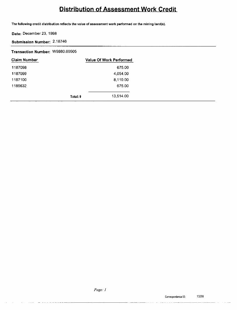
Distribution of Assessment Work Credit
The following credit distribution reflects the value of assessment work performed on the mining land(s).
Date: December 23, 1998
Submission Number: 2.18746
Transaction Number: W9880.00505
Claim Number Value Of Work Performed
1187098 675.00
1187099 4,054.00
1187100 8,110.00
1185632 675.00
Total:* 13,514.00
Page: J
Correspondence ID: 13209
"W r l V
r
32D04NE2011 2.18746 MCGARRY 200
OSSIAN TWP.
- -43M
1205892189648 l .146281 i
\- l l OJ !— — 1 _ - _ ^ LOO ~~"
-J2J.76.8j I2C5890
1200023 I2026?0l i1189647 i 1146394 \ 1189649 l S l 1169653 , CO
' ' '-.L ...J-1!
— - - — — Al
I225091
II89646 120030^
s i 1202672 j '/S, ' (NJT- - ~ - ~ - - J ——
l 870I4II93I2I \
225303.
i 11^5857 i sL 41006 L74I007
RIGHTS--LUfO
L 33164 , L i2399 l l. 12400l ^HICT l
L.36358~ L. 33033 —L.33325 U 40999 /L.
L' \33028- /L 50781
CLM 298/ UL 33804 \ 33803 L L E4 l ^^"40/0 4 9
-3-0-7-6-5 -i l. 6623 L.
765089 76509^
. 30768
765074C~r.
n86090 11186089
L 3 ..0^7 6 3
. .95IIIS2304 l IIS2304 80088®
/JKL. 32753 "15521L 2 6 3/3.^/1 . l r— IL 40802 U 40801
L
H6563I ^^Mll^85633
- -y-
^133049
36735\ 7 L 3347rH
737426O (. M l O
737433 - ^ l2 - *^-- '1180052 l \'\//^
tf/ Larder
X 1180058736734
1180057
. 33342 l1184102
THE INFORMATION THAT APPEARS ON THIS MAP HAS BEEN COMPILED FROM /ARIOUS SOURCES, AND ACCURACY IS NOT GUARANTEED. THOSE WISHING TO STAKE MIN ING CLAIMS SHOULD CON SULT WITH THE MINING RECORDER, MINISIflY OF NORTHERN DEVELOP MENT AND MINES, FOR AD DITIONAL INFORMATION ON THE STATUS OF THE LANDS SHOWN HEREON.
ARCHIVED MAY i. 1994
ARCHIVED JJNE 17/96
MCFADDEN TWP.
ID;u o
o rno
O
rn OD rn o
LEGENDfflGHWAY AND ROUTE No
OTHER ROADS
TRAILSSURVEYED LINES
TOWNSHIP;, BASE LINES. ETC LOTS, MINING CLAIMS. PARCELS, ETC
UNSURVEYED LINES LOT LINE:; PARCEL BOUNDARYMINING CLAIMS kETC
RAILWAY AND RIGHT OF WAY - UTILITY LINtiS ** ' NON-PERENNIAL STREAM FLOODING OR FLOODING RIGHTS '.
SUBDIVISION OR COMPOSITE PLAN
RESERVATIONS ORIGINAL SHORELINE MARSH OR MUSKEG MINES TRAVERSE MONUMENT
i i
DISPOSITION OF CROWN LANDS
TYPE OF DOCUMENT SYMBOLLAND USE PERMITS . . . . , . . . . . - . . . . . - - . L - J -p - PATENT, SURFACE 4 MINING RIGHTS....— ,...-.—— *
. SURFACE RIGHTS ONLY.. .......^.^.......— 9
. MINING RIGHTSONLY .... .. .................. CLEASE. SURFACE Si MINING RIGHTS...^— ......—. B
G-3163COPY OF THIS MYLAR*' ' ARCHh/ED OC T, 31. 1991
ARCHED APR, IS, 1
32D04NE2011 2.18746 MCGARRY 210
CDik)CD k)
DATE Of
O 6 1998
m-
THE INFORMANT THA~ APPEARS O' MAP HAS B^t 4 COM. LED FROM VAf ,OUS SOURCES AND ACCURACY IS NO - GUARANTFE&? THOSE WISHING TO STAKE MIN ING CLAIMS SHO'JLD CON GULT WITH 'HI IIMlNr, RECORDER MINISTRY OF NORTHERN DEVELOP MENT AND MINES, FOR AD DITIONAL ir FORMATIONON TnE STATUS OF THE LANDS SHOWN HEREON
oi
TRIM LINE
TOTAL CHARGEABILITY (mV/V)
2.1ST4 6?
800W 700W 600W 500W 400W 300W 200W 100 W 100E l
100S — O -^- —" —* DO -*-
200E 300E 400E 500E 600E 700E 800E 900E 1000El l l l l l l l l


![OUTER HOUSE, COURT OF SESSION [2018] CSOH 18 P220/17](https://static.documents.pub/doc/80x56/61ae3d46733144736b5ef97f/outer-house-court-of-session-2018-csoh-18-p22017.jpg)


