NASA TECHNICAL MEMORANDUM i NASA TM X-2956 HL-10 LIFTING BODY FLIGHT CONTROL SYSTEM CHARACTERISTICS AND OPERATIONAL EXPERIENCE by Weneth D. Painter and George J. Sitterle Flight Research Center Edwards, Calif. 93523 NATIONAL AERONAUTICS AND SPACE ADMINISTRATION • WASHINGTON, 0. C. • JANUARY 1974
Transcript
NASA TECHNICAL
MEMORANDUM
i NASA TM X-2956
HL-10 LIFTING BODY FLIGHT
CONTROL SYSTEM CHARACTERISTICS
AND OPERATIONAL EXPERIENCE
by Weneth D. Painter and George J. Sitterle
Flight Research Center
Edwards, Calif. 93523
NATIONAL AERONAUTICS AND SPACE ADMINISTRATION • WASHINGTON, 0. C. • JANUARY 1974
1. Report No.
NASA TM X-29562. Government Accession No. 3. Recipient's Catalog No.
4. Title and Subtitle
HL-10 LIFTING BODY FLIGHT CONTROL SYSTEM CHARACTERISTICSAND OPERATIONAL EXPERIENCE
5. Report DateJanuary 1971*
6. Performing Organization Code
7. Author(s)
_ _W.eneth p. J>ainter and George J. Sitterle
8. Performing Organization Report No.
H-704
9. Performing Organization Name and Address
NASA Flight Research CenterP. O. Box 273Edwards, California 93523
,10.,Wprk,Unit No. _ _
756-48-01-00
11. Contract or Grant No.
12. Sponsoring Agency Name and Address
National Aeronautics and Space AdministrationWashington, D. C. 20546
13. Type of Report and Period Covered
Technical Memorandum
14. Sponsoring Agency Code
15. Supplementary Notes
16. Abstract
A flight evaluation was made of the mechanicalhydraulic flight control system and the electrohydraulicstability augmentation system installed in the HL-10lifting body research vehicle. Flight tests performedin the speed range from landing to a Mach number of1. 86 and the altitude range from 697 meters (2300 feet)to 27,550 meters (90,300 feet) were supplemented byground tests to identify and correct structural resonanceand limit-cycle problems. Severe limit-cycle andcontrol sensitivity problems were encountered duringthe first flight. Stability augmentation system structuralresonance electronic filters were modified to correctthe limit-cycle problem. Several changes were madeto control stick gearing to solve the control sensitivityproblem. Satisfactory controllability was achieved byusing a nonlinear system. A limit-cycle problem dueto hydraulic fluid contamination was encountered duringthe first powered flight, but the problem did not recurafter preflight operations were improved.
17. Key Words (Suggested by Author(s))
Control systemAircraft control system
18. Distribution Statement
Unclassified - Unlimited
19. Security Classif. (of this report)
Unclassified
20. Security Classif. (of this page)
Unclassified
21. No. of Pages
34
22. Price*
$3.00
* For sale by the National Technical Information Service, Springfield, Virginia 22151
HL-10 LIFTING BODY FLIGHT CONTROL SYSTEM CHARACTERISTICS
AND OPERATIONAL EXPERIENCE
Weneth D. Painter and George J. SitterleFlight Research Center
INTRODUCTION
Space exploration has aroused considerable interest in the development of pilotedreentry vehicles that combine high maneuverability with the design and operational sim-plicity of the capsule configurations. Such a vehicle must be controllable enough toallow the pilot to control reentry operations, particularly during terminal guidance,navigation, and landing (refs. 1 to 3). Operational experience gained from flight testsof the HL-10 lifting body research vehicle (ref. 3) is believed to be a valuable sourceof data for defining control system requirements for such a vehicle.
The HL-10 was built under contract and delivered to the National Aeronautics andSpace Administration in March of 1966 for experimental flight testing at subsonic andlow supersonic speeds. Simplicity and reliability were emphasized in the design ofthe HL-10's flight control system, so standard aircraft design practices and existinghardware were utilized wherever possible. This paper describes the flight controlsystem and discusses the system's performance in flight and during ground tests. Theflight program was conducted jointly by the U.S. Air Force Flight Test Center and theNASA Flight Research Center at Edwards Air Force Base, Calif.
SYMBOLS
Physical quantities in this report are given in the International System of Units (SI)and parenthetically in U.S. Customary Units. Measurements were taken in Custom-ary Units. Factors relating the two systems are presented in reference 4.
b body reference span, m (ft)
L, moment of inertia of the vehicle about the X-axis,
kg-m2 (slug-ft2)
Iv moment of inertia of the vehicle about the Y-axis,2 2kg-m (slug-ft )
moment of inertia of the vehicle about the Z-axis,
6
2 2kg-m (slug-ft )
K roll damper gain, — — , deg/deg/sec
eK pitch damper gain, —, deg/deg/sec
6K yaw damper gain, —, deg/deg/sec
Rolling moment per 6 „Lfi roll control power, = —, rad/sec /rad
a LX
Pitching moment per 6 „Mr pitch control power, ; , rad/sec /rad
e V
Yawing moment per 6 ~Ng yaw control power, ^, rad/sec /rad
6o +6oL R60 longitudinal control deflection, , deg
6 £
6 rudder deflection, 6 + 6 , degr rL rR
Subscripts:
L left
R right
DESCRIPTION OF THE VEHICLE AND FLIGHT CONTROL SYSTEMS
The HL-10 lifting body vehicle (fig. 1) is basically a flat-bottomed, boattailed,negative-cambered airfoil. It is 6.45 meters (21. 17 feet) long and 4.15 meters(13.6 feet) wide. Two end-plate fins with outboard-cambered leading edges and a ver-tical centerline fin are located near the rear of the vehicle. The single-place vehiclehas a conventional tricycle landing gear which can be extended in flight (prior to touch-
-down)-but~eannot-be-retracted-in-flightv--The-vehicle's-launch-weigMrduring the-powered^flight program was approximately 35,586 newtons (8000 pounds), and its landing weightwas approximately 26,690 newtons (6000 pounds). Additional vehicle physical character-istics are listed in table 1.
Primary Flight Control System
The primary flight control system is an irreversible, dual, electromechanicalhydraulic system with an artificial feel system. The irreversible characteristic ofthe hydraulic system holds the control surfaces steady against forces that do not origi-nate in pilot control movement and prevents such forces from being transmitted backto the pilot's controls.
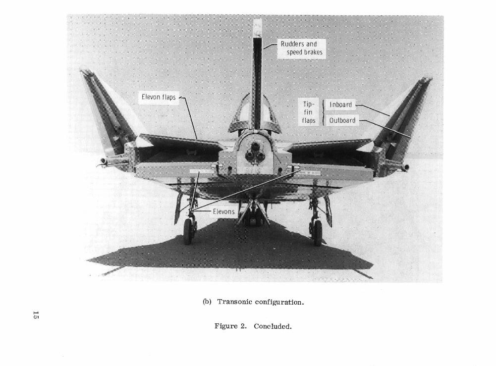
Aerodynamic control is provided by 10 control surfaces (figs. 2(a) and 2(b)): two ele-vens, two eleven flaps (one on each elevon), four tip fin flaps (two inboard and two out-board), and two rudder surfaces. The geometry of the aft end (boattail) of the vehiclecan be varied by moving the rudders and the flaps on the elevens and tip fins. Forsubsonic flight (fig. 2(a)) the flaps and rudders are boattailed (fully retracted), whichcauses the vehicle to be shaped like an airfoil. When the flaps are fully extended(fig. 2(b)), the control surfaces form a shape like a wedge, which is necessary for tran-sonic flight to improve stability and control. In this configuration each rudder is ex-tended 8°. The rudders can be further extended, to 32° each, for use as speed brakes.The flaps are operated by electric motors and jackscrews, and are controlled by switchesin the cockpit. The speed brakes are operated by utilizing the main rudder actuators,which are driven by electric motors and jackscrews, and they are controlled by a switchon the landing rocket throttle handle in the cockpit. Control-surface authorities areshown in table 2.
The vehicle has a conventional fighter airplane cockpit (figs. 3(a) to 3(c)) with astandard control stick and rudder pedals. As shown in figure 4, a diagram of the flightcontrol system, the control stick is' connected by cables and push rods to the hydrauliccontrol valves on the actuators located at the right and left elevons. Moving the stickpositions the control valves so that hydraulic power is directed to the control-surfaceactuators to move the control surfaces. A mechanical followup system shuts off the flowof hydraulic fluid to the actuators when the desired control-surface deflection is reached.
Forward and aft control stick motion causes synchronous elevon operation for pitchcontrol. Aft stick travel causes the left and right elevon surfaces to deflect trailingedge up with reference to the bottom contour of the vehicle, and forward stick travelcauses the left and right elevon surfaces to deflect trailing edge down with reference tothe bottom contour of the vehicle.
Left or right control stick motion causes differential eleven operation for roll con-.trol.-a
Rudder pedal motion causes the two panels of the split rudder on the center verticalfin to operate in unison for yaw control.
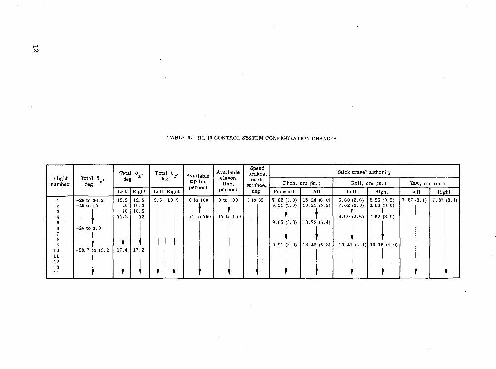
Control System Configuration
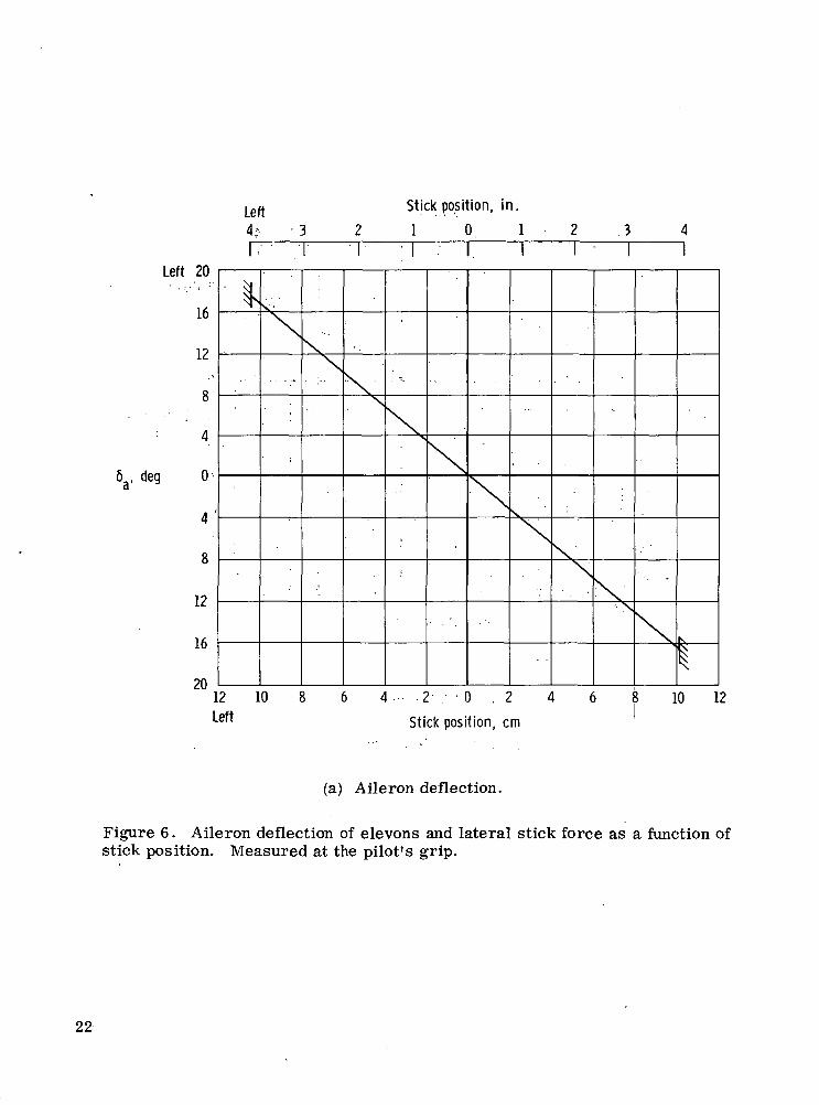
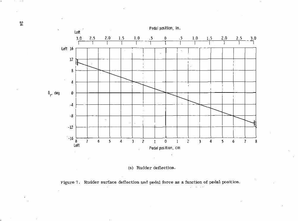
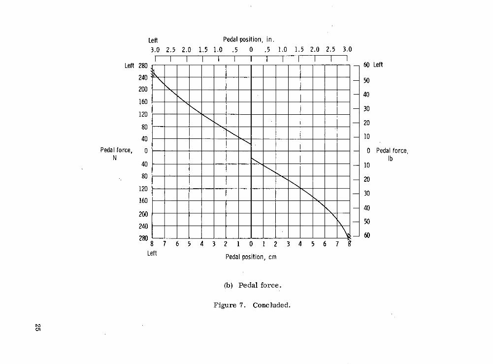
The changes made to the control system configuration for flights 1 to 14 are pre-sented in table 3. No changes were necessary after flight 14. The longitudinal controlsurface to stick gearing changes are shown in figure 5(a), and the longitudinal forcegradient is shown in figure 5(b). The lateral control surface to stick gearing is shownin figure 6(a), and the lateral force gradient is shown in figure 6(b). The directionalcontrol surface to pedal gearing is shown in figure 7(a), and the directional force gra-dient is shown in figure 7(b).
Artificial Feel and Trim Systems
The artificial feel system gives the pilot a sense of control feel under all flight con-ditions. Stick and rudder pedal forces were provided by coil spring bungees in the con- .trol system. The bungees apply loads to the pilot's controls in proportion to stick orpedal movement, but the resultant feel has no relation to actual air loads.
Pitch and roll trim are achieved by moving the four-position switch at the top of thecontrol stick. Activating the switch energizes an electric motor which changes theneutral position of the coil spring bungees connected to the control stick. A yaw trimswitch on the left console permits the neutral force position of the rudder pedals to beadjusted.
Stability Augmentation System
The stability augmentation system (SAS) provides damping for the aerodynamicflight control system in the pitch, roll, and yaw axes. The system has a monitor chan-nel in each axis to detect malfunctions in the primary channel and to provide fail-operate in pitch and fail-safe in roll and yaw. The intent of the system's design is toinsure that no single failure disables both the primary and the backup channels.
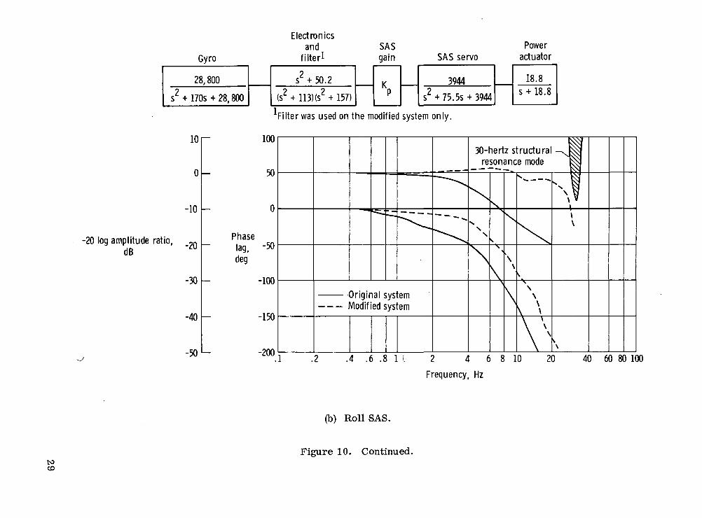
Internally, the power distribution circuitry is such that the pitch and roll primarychannels are separate from the pitch and roll backup channels and the yaw primary chan-nel. A functional block diagram of the SAS is shown in figure 8. The five functionalchannels, two (primary and backup) in pitch and roll and one (primary) in yaw, consist ofa rate gyro, an electrical assembly, a protective circuit, and a hydraulic actuator. Thefeedback signal from the actuator is compared with the signal from a model of theactuator in the monitor channel. When the difference between the feedback signal andthe model signal exceeds a certain (adjustable) threshold, the monitor senses an errorand switches either to the backup channel (for pitch and roll) or off (for yaw).
The yaw axis electronics incorporate a high-pass filter for the washout of steadyrates. The filter permits the desired high-frequency signals from the gyro for vehicle
damping to pass, and blocks unwanted steady-state signals from the gyro during turns.
The control switches for the SAS are in the cockpit on the left console. The on-offswitches are magnetically held when the on position is selected, and protective circuitsaround the servoactuator drive circuit cause the switch to disengage if a malfunctionoccurs. Voltage-sensitive circuits are used.
If a discrepancy occurs between the primary and monitor channels in the pitch axis,
the pilot's instrument panel lights. The pilot has a three-position toggle switch for thepitch axis. (The spring is loaded to the primary. ) The positions are reset (forward),primary (intermediate), and backup (aft). The primary (intermediate) switch position isnormal. After a malfunction, the pilot can reset the system in the primary mode bypushing the switch forward and releasing it. To switch to the backup mode, he movesthe toggle aft.
If a malfunction occurs in the roll axis, the primary channel goes off and the pilothas the option of selecting the roll backup channel manually by placing the roll backupswitch in the on position. The yaw axis does not have a backup channel.
The SAS gain selector switch in each axis controls the ratio of surface displacementto the angular rate signal through a variable resistor. The selector switch has 11 posi-tions, 0 to 10, and system gain increases linearly to a maximum of 1 deg/deg/sec atposition 10 in all three axes.
Hydraulic Power Supply Systems
The vehicle has two 20.685 X 10⁶ N/m2 (3000 lb/in2) hydraulic systems (fig. 9).The two systems have independent electric power and hydraulic pumps, but operatesimultaneously to supply vehicle hydraulic pressure. With both hydraulic systemsoperating, the control system has full hinge-moment and maximum rate capability. Ifone hydraulic system fails, the control system has only one-half the hinge-momentcapability but the same maximum rate capability. The number 1 hydraulic system servesas the sole power source for the pitch and roll SAS servoactuators, with a ram air tur-bine backup hydraulic system. The number 2 hydraulic system provides the solehydraulic power source for the yaw SAS servoactuator.
SYSTEM DEVELOPMENT PROBLEMS
Stability Augmentation System Hardware Problems
The HL-10's original SAS equipment was identical to that used in the M2-F2 liftingbody vehicle except for the structural filters. Experience with the SAS in the M2-F2(ref. 1) revealed certain deficiencies in the roll and yaw SAS channels, such as poormonitor channel tracking and nuisance disengagements. It was decided to correct theseproblems early in the HL-10 program, although not necessarily for the first flight. TheSAS configuration for the HL-10's glide flight envelope was much the same as it was forthe M2-F2's. Problems did occur during the first flight, such as aft end separation
over the elevens (ref. 2), control system limit cycles, and overs ens itivity in longitudinalcontrol. After an assessment of the problems encountered during the first flight, and areassessment of the known deficiencies, modifications were made.
When the reliability and operational integrity of the modified SAS were reviewed, adeficiency was discovered in the design of the monitor channels. The system had moni-tor channels in pitch, roll, and yaw so that no single failure could disable the total sys-tem. However, the monitor channels did not track the primary channels properly, withthe result that continuous nuisance tripouts occurred in pitch, roll, and yaw stabilityaugmentation. A failure in either the 15 Vdc or the -15 Vdc power supply would havecaused a hard-over condition in all three axes. In addition, a single failure in any of theother monitor power supplies (±12 Vdc, -6 Vdc, 40 Vdc, or 7.5 Vac) would have causeda loss of operation in all three working channels. Rather than make major modificationsto the monitor box, which would have meant a long delay in the flight program, the rolland yaw monitor channels were deactivated by removing the roll and yaw circuit boardsfrom the monitor box, and a maximum effort was made to keep the monitor channel inthe pitch axis working during flight.
Another problem was discovered when the pitch backup mode was engaged while theprimary channel was engaged. It took approximately 4 seconds for the pitch magneticswitch to disengage. During this time, the circuit to the pitch SAS servo was open,causing the eleven control surfaces to move with the drifting SAS servo. Minor circuitchanges were necessary to change the tripout voltage level which activated the pitchbackup reset switch. The total delay for the transfer was reduced to 400 milliseconds,which was the time it took for the eleven surfaces to reach 40 percent of the limitedSAS authority at maximum slew rate. This delay was considered operationally accep-table.
Closed-Loop Ground Tests
During the ground tests of the modified SAS, a structural mode vibration was en-countered in the pitch and roll axes. The structural vibrations were excited by placingthe SAS gains at 1. 0 deg/deg/sec and applying a momentary torquing signal to the gyro.Vibrations from the control surfaces were sensed by the gyros, which transmitted sig-nals to the control surfaces through the SAS. A self-sustained control-surface oscilla-tion resulted.
The structural resonance frequencies were found to be 24 hertz in the pitch axis and30 hertz in the roll axis. These resonance frequencies were high enough to be filteredwithout seriously degrading the control system's response at the lower SAS operatingfrequencies as shown by the pitch and roll frequency response plots in figures 10(a) and
These figures show that the phase lag was reduced and the amplitude ratio in theSAS operating frequencies was increased by the modification of the pitch and roll SAS.The modification was accomplished by using lead networks and notch filter networks inthe electronics portion of the SAS. As shown in figure 10(c), no structural resonanceproblems were encountered in the yaw axis, so no modifications were necessary.
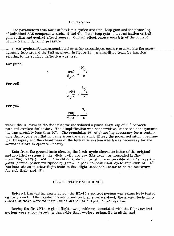
Limit Cycles
The parameters that most affect limit cycles are total loop gain and the phase lagof individual SAS components (refs. 5 and 6). Total loop gain is a combination of SASgain setting and control effectiveness. Control effectiveness consists of the controlderivative and dynamic pressure.
-Limit-cycle-tests-were,conducted-by usmg-an,analog_computer_to^simulate_the_aer_Q=dynamic loop around the SAS as shown in figure 11. A simplified transfer functionrelating to the surface deflection was used.
For pitch
For roll
For yaw
LfiP(s) a
N,r(s) °r6r(s) s
where the s term in the denominator contributed a phase angle lag of 90° betweenrate and surface deflection. The simplification was conservative, since the aerodynamiclag was probably less than 90°. The remaining 90° of phase lag necessary for a contin-uing limit-cycle oscillation came from the electronic filter, the power actuator, mechan-ical linkages, and the cleanliness of the hydraulic system which was necessary for theservoactuators to operate linearly.
Data from the ground tests showing the limit-cycle characteristics of the originaland modified systems in the pitch, roll, and yaw SAS axes are presented in fig-ures 12(a) to 12(c). With the modified system, operation was possible at higher systemgains (control power multiplied by gain). A peak-to-peak limit-cycle amplitude of 0.5°has been shown in other flight tests at the Flight Research Center to be the maximumfor safe flight (ref. 5).
FLIGHT-TEST EXPERIENCE
Before flight testing was started, the HL-10's control system was extensively testedon the ground. After system development problems were solved, the ground tests indi-cated that there were no instabilities in the basic flight control system.
During the first HL-10 glide flight, two problems associated with the flight controlsystem were encountered: undesirable limit cycles, primarily in pitch, and
overseasitivity in longitudinal control. The limit cycles were only an annoyance tothe pilot during the initial portion of the flight, but when the control power was higher,the limit cycles became large-amplitude oscillations. The highly sensitive pitch con-trol compounded the problem. To arrest the limit-cycle oscillations, the pilot wasforced to reduce the SAS gains and to continue the flight with less pitch damping despitethe high control sensitivity. This resulted in pilot-induced oscillation tendencies duringthe approach and landing. The pitch limit cycle experienced during the first poweredflight was found to be due to the presence of contaminated hydraulic fluid in the valveof the servoactuator, which caused the operation of the control system to be nonlinear.An operational procedure was established wherein additional preflight samples of thehydraulic fluid at the valve were taken to determine the level of hydraulic fluid con-tamination, and the problem did not recur.
After the first glide flight, several changes were made to the control system(table 3). The stick gearing was changed to give the pilot -24°' of aft stick and 10° offorward stick. This gearing was evaluated during the next four flights, and longitudinalcontrol was found to be less sensitive at low angles of attack, although it was stilltoo sensitive during the landing portion of the flight. The gradient of the longitudinalgearing was then reduced, to -25° of aft and 3° of forward stick. This improved thehandling qualities during the landing phase, but the vehicle was harder to fly at lowangles of attack. The longitudinal changes between flights 1 and 9 were all linearchanges, and since a flat slope was required for landing and a steeper slope was re-quired for low angles of attack, nonlinear gearing was tried next. Nonlinear gearingwas used for the remainder of the glide flight program and throughout the rocket-powered portion of the flight program (ref. 3).
The aileron authority was changed from 10° to 20° after the first flight. After thethird flight the authority was again changed, to 12. 5° of aileron for ±7. 62 centimeters(±3 inches) of stick travel, and it remained at this level through flight 9. From flight10 on, the lateral stick gearing was not changed, but the pilot's authority was increasedto 17° with ±10.16 centimeters (±4. 0 inches) of lateral stick travel.
CONCLUDING REMARKS
Flight- and ground-test experience with the HL-10 lifting body flight controlsystem brought to light several problems that required correction in order to achievesatisfactory vehicle stability and control characteristics.
In general, the mechanical control system met the operational requirements ofthe test vehicle. The control stick gearing was made nonlinear to improve thevehicle's control sensitivity.
A severe limit cycle, or residual oscillation, was observed in the pitch axisduring the first flight. Improved operational procedures resulted in reduced hydraulicfluid contamination levels and eliminated the limit cycle.
A structural resonance encountered in ground tests of the modified stability augmen-tation system was eliminated by filtering the electronic signals.
Flight Research CenterNational Aeronautics and Space Administration
Edwards, Calif., September 14,1973
REFERENCES
1. Painter, Weneth D.; and Kock, Berwin M.: Operational Experiences and Charac-teristics of the M2-F2 Lifting Body Flight Control System. NASA TMX-1809, 1969.
2. Harris, Charles D.: Transonic Aerodynamic Characteristics of a Manned LiftingEntry Vehicle With Modified Tip Fins. NASA TM X-1918, 1970.
3. Kempel, Robert W.; and Manke, John A.: Flight Evaluation of the HL-10 LiftingBody Handling Qualities at Mach Numbers From 0. 30 to 1. 86. NASA TN D-7537,1973.
4. Mechtly, E. A.: The International System of Units - Physical Constants and Con-version Factors (Revised). NASA SP-7012, 1969.
5. Painter, Weneth D.; and Sitterle, George J.: Ground and Flight Test Methods forDetermining Limit Cycle and Structural Resonance Characteristics of AircraftStability Augmentation Systems. NASA TN D-6867, 1972.
6. Kotfila, Ronald P.; and Painter, Weneth D.: Design, Development, and FlightTest Experience With Lifting Body Stability Augmentation Systems.AIAA Paper 69-887, 1969.
TABLE 1.- PHYSICAL CHARACTERISTICS OF THE HL-10 LIFTING BODY VEHICLE
Body - 2 2Reference planform area, m (ft ) 14. 9 (160)Length, m (ft) 6.45 (21.17)Span, m (ft) 4.15 (13.6)
b2
Aspect ratio (basic vehicle), —5— 1.156o
Weight, including pilot, N (Ib) 26,690 (6000)Center of gravity, percentage of reference
length 51.8Elevens (two) -
Area, each, m2 (ft2) 1.00 (10.72)o 2
Reference area, m (ft ) 0.82 (8.89)Span, each, parallel to hinge line, m (ft) 1.09 (3.58)Chord, perpendicular to hinge line:
Root, m (ft) 0.59 (1.93)Tip, m (ft) 1.24 (4.06)Reference chord, m (ft) . . . 0.76 (2.48)
Eleven flaps (two) -
Area, each, m2 (ft2) 0.70 (7.50)Span, each, parallel to hinge line, m (ft) 1.09 (3.58)Chord, perpendicular to hinge line:
Root, m (ft) 0.48 (1.58)Tip, m (ft) 0.80 (2.63)Reference chord, m (ft) 0.64 (2.09)
Vertical stabilizer -
Area, m2 (ft2) 1.47 (15.8)
Reference area, m2 (ft2) 1.38 (14.85)Reference span, m (ft) 1.48 (4.84)Height, trailing edge, m (ft) 1.53 (5.02)Chord:
Root, m (ft) 1.32 (4.32)Tip, m (ft) . . 0.60 (1.97)Reference mean aerodynamic chord, m (ft) 0. 98 (3. 23)Leading-edge sweep, deg 25
Rudders (two) -Area, each, m2 (ft ) 0.41 (4.45)Height, each, m (ft) 1.26'(4.12)Chord, m (ft) 0.33 (1.08)
Outboard tip fin flaps (two) -2 2Area, each, m (ft ) 0.35 (3.77)
Height, hinge line, m (ft) 1.37 (4. 50)Chord, perpendicular to hinge line, m (ft) 0. 26 (0. 84)
Inboard tip fin flaps (two) -Area, each, m2 (ft2) 0.23 (2.48)Height, hinge line, m (ft) 1.01 (3.31)Chord, perpendicular to hinge line, m (ft) 0. 23 (0. 75)
10
TABLE^2 . ,HL^1 O^CON.TRQL-SURFACE AUTHORITY
Surface
Eleven
Eleven flaps
Tip fin flapsOutboardInboard
Rudder
Speed brakes
Input
Pitch trim switchPitch control stickPitch SASAileron trim switchAileron control stickRoll SAS
Switch
Switch •
Rudder trim switchPedalYaw SAS
Switch
Travel, deg
-19 to 6-24 to 13±5±5±17±5
0 to 29
0 to 320 to 30
±5±10±5
0 to 32
Rate, deg/sec
225250.65050
3
33
12525
3
11
to o. .
(M C
O
o o
:C
O
CO
S2,rHC
TJ
n
M
„ i_« g
a j
»
^3
n
8
a .oB
£
3
-i- h
§1
S §
12
o05
*!<
0)
102s<D
13
aoCeSooflo
bJD
oiHI
ffi*4-lO<B•i—
i
03
K<DFH
14
O•I-H
tsf-tfiooo•I—I
PIo<M
15
COoC
Oo(MIH
'Ooj
c
R0)eojFHC3a1oo«HKCOe
16
oCOo<MIH
£oCQ
aooi-le
I•r-i+JcoCObe
17
oCOoIN
ooIs
T30soooo8
18
CO8-l->§u-t->
•as19
Trailing edge 40down
36
32
28
24
20
16
12
86e. deg
4
0
-4
-8
-19LL.
-16
-20
-24
-78
Af» OULK pUMUUM, Ml.
6 5 4 3 2 1 0 1 2I I I I I
Yw/
/*£
//
stX
Freeflight
number12 to 56 to 910 to 1314 to 37
•',
/
X"
//
s
'*?>
/
^
//
'#V
1 1
/
fS
Mr
X
//
f/
/
/f
//S f
s
3 .1
/,
'//'
/
N
As
^
16 14 12 10 8Aft
6 4 2 0Stick position, cm
10
(a) Eleven deflection.
Figure 5, Longitudinal eleven deflection and longitudinal stick force as a function ofstick position. Measured at the pilot's grip.
20
Push 160
120
80
40
0
Stick force, 40N 80
120
160
200
• 240
?8fl
Aft Stick position, in.6 5 4 3 2 1 0 1 2 3 41 1 1
/
^
//
/
\ \
/
x
'
/
/
\ \ \
/^^
S^
\
*,\\.
—
-30 Push
-20
-10
-0
-10 Stick force,
-20 'b
-30
-40
-50
-fin16 14 12 10 8Aft
6 4 2 0 2 4 6
Stick position, cm
10
(b) Stick force.
Figure 5. Concluded.
21
Left Stick position, in.
4 ; : 3 2 1 0 . 1 2 3
Left 20
16
12
8
: 4
6,, deg 03
4 '
8
12
16
?n
\ ,
1V
\
• \' " \ : \ \ I - \ \
\\V
N
.'--
k;
\
\
\\
X
-
N^
\^K
12 10 8 4 2 - 0 . 2 4 6
Stick position, cm
8 10 12
(a) Aileron deflection.
Figure 6. Aileron deflection of elevens and lateral stick force as a function ofstick position. Measured at the pilot's grip.
22
o>
C3
o>l_OJ^ :
O(/I
OsQ.
C\J
Q
)
s<=>
S
§
S
0)O^.2^1a
0)OCOu2
Oiy-!
23
oroT3<U
D.
OCM
oto•o0>Q
.
§O)
T3fn0)Oj
Owa•3I-i-joIcS0)ooi•o0)ft13O01T30)OO
j
s0)
e-0)
24
CO
inCM
Or— 1
O(—1
.E
in
o8.•aC
Da.
0in• — i
inCM
c °
£aCv*
~——1 ———
cc 5j33
7-6
3 $
M
0
1
/
'*J C
\
1/
/> s
J 1-
1/'i g-t
r-
S1/
/3
CJ
O-i
01A
/f
8 i
aic»*.
"nTCQC
/?
C
1>J3I J3
0•303 e
/
3
C
3—11
/
/? s 1/xg
g
Cn/•j-1
3•>
/
/S
1//1
1
Ss
/33M
?^C
S
sI I
ocooo.
1 '
m•aa>rv
i Q
-
»-
u
0)
I•a
1OSoo
CD
OCO
•g
Q_
25
roo
~ E
Q-
'»-
0.
O>-
oo E
o 'c
o: oE
26
Right eleven
Roll SAS
Pitch SAS
Yaw SAS-Rudder
Number 1 hydraulic -^• system /
• / Left eleven
Number 2 hydraulic system
-Ram air turbine
Figure 9. Schematic of vehicle hydraulic systems. (Return lines not shown.)
27
CD
oCD
OO3t/)
ii~CD
ocCD
CV
J I i
03<;0)ctf
0)oe«t;3COIO•UOftsoenIo-t-»
u0>CQIw0)oa(Dcr0)
oooC
M
OO
CM
Ot—
CI
CD
T3
±i OQ
Q.'O
Eroo
BOS
Or-(
VE
28
CO3O0>to
OO
OO
00
C
00 '&
e?
5•G
ro E
Q>
"~
o
ooOO
1 — 1
Ii.
CVJ
8CVJto
OO
CVJ
OO
OOtIr~-
CV
Jto
O-
/
ir\+C
VJ1 — 1
CVJoo"C
vj
tos1 — 1
CVJto
coECD
ECD
COtoCO
NUcCD
CC
<COI—(
•3rt
"8I-(->§o
Lo
o'toeCOCJ1
_o
29
<C1/1
to
ooooi — i
I
oooo+l/>3&+«ir\r—
CMi/>
^~IK0LTl
Jfl
1/1
oo"C
M
oo"00
C5
r—i — i
+C
Ml/>
Oo
O00
CD
00
^CT
CD
vO
ul
8
031
TJ0)o§o0>
o'2CD
•a3SS
C
Q"E(a
30
13Q.
c21ol
Control-surface'Mechanical-
H<.
10 ~E<
«00 -sXj
VI
% .E
Q"
en
JSAS electronicsJcJ
power actuatorsCDCT>
roJ^ci?i§i« a
o. o>
°s-^--. Q
J
C
T3
S ~
5l
0 Q
J
•D
bOi_O>
•ocro
'D11
ace deflection, deq
T:onle"c0o
iLa-*.£c<.
. |nC<oCO
W1
s•oCD'
2v_JS3a-c:i
CQ-(->CQ
5O)
u0-M•»-(s•rHr—
(
CO<CQ.3-a0)
CQ3CQ-fJ0)1so
5 o
:
i-i
L cs
=• c
5 ^
3 3
r x
5 ®
:
73§<U4->
CQi of control syftgS
1•1-1T
3
P«CJ
,2«r-liH2a•rH
rH
31
deg
Maximum control powerexperienced during flight—j
3 '
Unacceptable
Original systemModified system
•/////////, Flight Research Center criteria
Limit-cycle frequency, Hz
10 20K JV\5 . per sec
q e
30 40
(a) Pitch axis.
Figure 12. Limit-cycle characteristics of the pitch, roll, and yaw axesbased on ground tests.
32
Maximum control powerexperienced during flight
Original systemModified systemFlight Research Center criteria
y
2
KpAp, deg
1
n
Unacceptable
Acceptablef*=^-~~
s<•*
}4 ;
y•,
Limit-cycle frequency, Hz
10 20 30 40KpL6 , per sec
(b) Roll axis.
Figure 12. Continued.
33
deg
Limit-cycle frequency, Hz
A/////////X p
Maximum control powerexperienced during f light -7
3
2
ii
0
/
U
.
T1i
lacceptable
AcceptableK ^— -^ •• "• ""^
//
^_^.-
11iI1iI
/
.„„}„,„.
."
5
4
Q
z
0
1
0
^
/''
^
tf
s
/
/
'
^
10 20 30 4
K N, , per sec
Original systemModified systemFlight Research Center criteria