Holographic Data Storage and Image Compression Ravinder Kumar Benyal “Data storage and retrieval using photorefractive crystals (Holographic Memories)” Thesis. Indian Institute of Astrophysics Bangalore, University of Calicut, 2005
Transcript
Holographic Data Storage andImage Compression
Ravinder Kumar Benyal “Data storage and retrieval using photorefractive crystals (Holographic Memories)” Thesis. Indian Institute of Astrophysics Bangalore, University of Calicut, 2005
Chapter 4
Holographic Data Storage and
Image Compression
Introduction . At basic level, a hologram is a record of t,he spa,tial interference pattern formed
by mixing of two coherent laser beains. One of t,he recording beains which carries
spatial information is labeled as object beam. The other is a. plane beam ilornlally
distinguished by its particular direction of travel and labeled as reference beam.
The object beam is re~onst~ructed by illuminat,ing the recorded hologram with the
reference beam and vice-versa. In a thick storage medium, t,he reconstruction be-
comes very sensitive t,o the particular angle of incidence of the reference bea.m,
which allows multiple pages to be recorded in the same volume. The dat>a pa.ges can
be recorded sequentially, by simult~aneously illuminating the phot~oseasitive mater-
ial with the object beam and its unique reference beam. Each hologram can be a
read-out. independently by associated reference beam.
A pixel is a smallest unit in a digital image. Associated with each pixel is a
number, in the interval [O, L], representing grey level ranging from black (0) to
white (L). In a binary image, the pixel value is eit)her 0 or 1. For a n-bit grey scale
image, a pixel can have value a,nywhere between 0 (black) and 2" - 1 (tvhit'e). For
example, in a 8-bit grey scale image, a pixel may have any integer value bet'mreen 0
and 255.
73
Chapter 4. Holographic Data Storage and Image Compression 74
A holographic data storage system (HDSS) works fundamentally on a page-
oriented architecture that has a tremendous potential to store pictorial (gray scale
images) as well as binary data. A11 optical replica of binary or a grey scale data
page is created by liquid crystal based spatial light ~nodulat~or (SLhI).
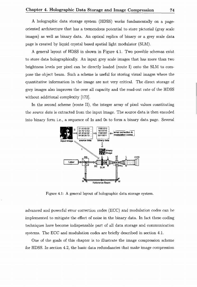
A general layout of HDSS in shown in Figure 4.1. Two possible schemas exist
to store data holographically. An input grey scale images that has more than two
brightness levels per pixel can be directly loaded (route I) onto the SLlI to com-
pose the object beam. Such a scheme is useful for storing visual images where the
quantitative information in the image are not very critical. The direct storage of
grey images also improves the over all capacity and the read-out rate of the HDSS
without additional complexity [172].
In the second scheme (route 11), the integer array of pixel values constituting
the source data is extracted from the input image. The source data is then encoded
into binary form i.e., a sequence of 1s and OS to form a binary data page. Several
I I . . . . . . I]! . . . . .< .. , source data binary data
Figure 4.1: A general layout of holographic dat,a storage systern.
advanced and powerful error correction codes (ECC) and modulation codes can be
implemented to mitigate the effect of noise in the binary data. In fact these coding
techniques have become indispensable part of all dat,a storage and comnlunication
systems. The ECC and modulation codes are briefly described in section 4.1.
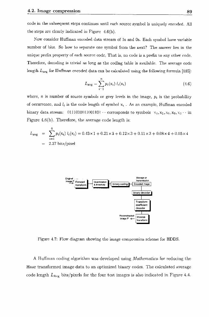
One of the goals of this chaptJer is tto illustrate the image compression scheme
for HDSS. In section 4.2, the basic data redundancies that make image compression
4.1. Error Correction and Modulation Codes 75
possible, are described. The Haar transformation based image con~pression and its
inlplemcntation using matrix algebra is explained subsequently. Huffman encoding
of binary data is explained next. Iniage compression algorithm was developed and
quantitative results obtained for some of the test images are presented. A block-
based rneanlmedian approach is suggested to distinguish between logical 1s arid
OS in a CCD captured image. The experimental scheme developed for HDSS is
presented in section 4.3.1. The storage of binary and grey scale astronomical images
in Fe:Ce:Ti doped LiNb03 crystal is demonstrated, respectively, in sections 4.3.2
and 4.3.3.
Error Correction and Modulation Codes
Noise and error sources are mechanisms through which information is eit,her cor-
rupted or lost while recording aad/or retrieving the data. For example, packing
data bits more densely bring them t,oo closer to each other's proximity such t,hat
t,heir boundaries begin to merge. This leads t,o destructive influence of inter-symbol
interference (ISI). In addition, by increasing rea.ding> recording and transfer rate
results in distorted data readout. The error is usually quantified by a term known
a.s bit-error rate (BER), defined a.s the ratio of number of error bits in the output,
stream to the total number of data bits in the input stream. In a typical st,orage
media, the raw BER is around 10-3 - 10-% However, the acceptable standard for
BER in the present storage devices is of t,he order of FZ 10-l' or bet,ter.
The error detection and correct,ioil codes a,re designed to impa.rt. certain degree
of imlnunit,y t'o t'he da,t,a. bits against the noise. It is a,ccomplished by selectively
introducing redundant bits into the source data prior to storage. These additional
bit,s (also called overheads) a.llow detection and correctlion of bit, errors in the re-
trieved data from the noisy environment. The overhead cost associa,ted with ECC is
characterized by the code rate: k ln , where k is source data bits and n is code word
length. The coding redundancy is measured by the number of extra. bit i.e., n - k .
Main examples of ECC codes are: parity checl<s code, Hamnling code, Reed-Muller
code, Reed-Solomon code and Turbo code [173].
4.2. Image compression 76
In page oriented data storage system, the occurrence of some of the bit patterns
contribute more noise than others. In addition, certain bit pattern nlay be more
suitable for a given detection scheme. Therefore, the purpose of modulation codes
is to permit the appearance of selective patterns in the binary data page and inhibit
the pattern that are more prone to noise. In a p : q modulation code; p is the length
of source bits and g-p is the number of ext,ra or overhead bits required to achieve
the desired modulation. The overhead is usually described in terms of code ratio,
p19 < 1.
The error correction and nlodulation codes, though extremely useful in preserving
the data fidelity, have undesirable effects on the storage capacity of the medium due
to increased overhead rates. The effective storage capacity of the syst,em drastically
reduces due t,o inclusion of overhead data. One of the ways to overcome this lirnita-
tion is to compress the source data before applying the ECC arid modulation codes.
Efficient data compression algorithms can effe~t~ively compensate for the overhead
pellalty paid in ECC and nlodulation coding. The objective of data compression is
to reduce the number of bits required to convey the useful information in a source
data. The data coinpression is possible because most real-world data is statistically
redundant. The implementation of Several ECC and modulation codes for holo-
graphic inemories have already been demonstrated in the past [63,70-72,74,174].
Without taking further recourse to ECC and modulation codes, the next section
explains the principle of image compression.
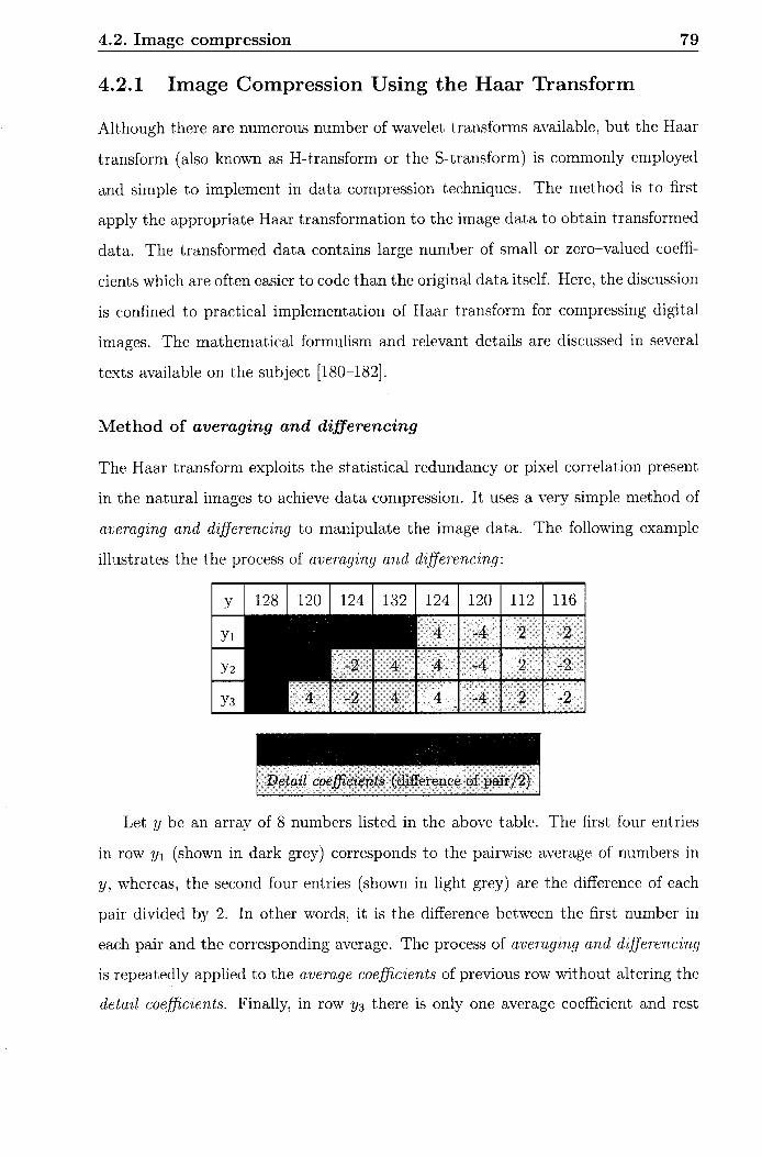
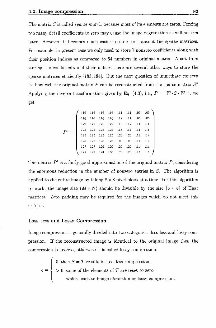
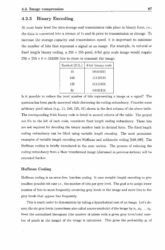
4.2 Image compression
An image is a two-dimensional repre~ent~ation of some physical data or signal which
conveys some meaningful information. The image coinpression addresses the issue
of reducing the amount of data required to represent a digital image. Most of
the natural images have certain statistical properties which can be exploit.ed to
achieve the compression. Different amount of data may be used to convey the same
information. In that sense, the extraneous data that does not provide any new or
extra information leads to data redundancy. The underlyirlg basis of the reduction
4.2. Image compression 77
process is to remove the da,ta redundancy. In most of the digita,l images, t,hree types
of data redundancies can be identified. These are: interpixel redundancy, coding
redundancy and psychovisual redundancies.
Interpixel redundancy arises froin t,he correlation among the pixels due to struc-
tural or geometrical siinilarities between the objects in the image. In such a case, it
is possible to approxiinate a pixel va.lue from t,he neighbouring pixels. The iriterpixel
redundancy in an image can be reduced by tra,nsforming the two-dimensional pixel
a.rray into a. more efficient and often nonvisual format. This is discussed in section
on Haar transform.
Usually in a digital in~a~ge, the number of bits used for t,he representation of each
pixel is constant for all the pixels, regardless t,he value of the pixel and the frequency
of occurrence of t8hat value in the image. In most of t,he na,tural images, cert'ain grey
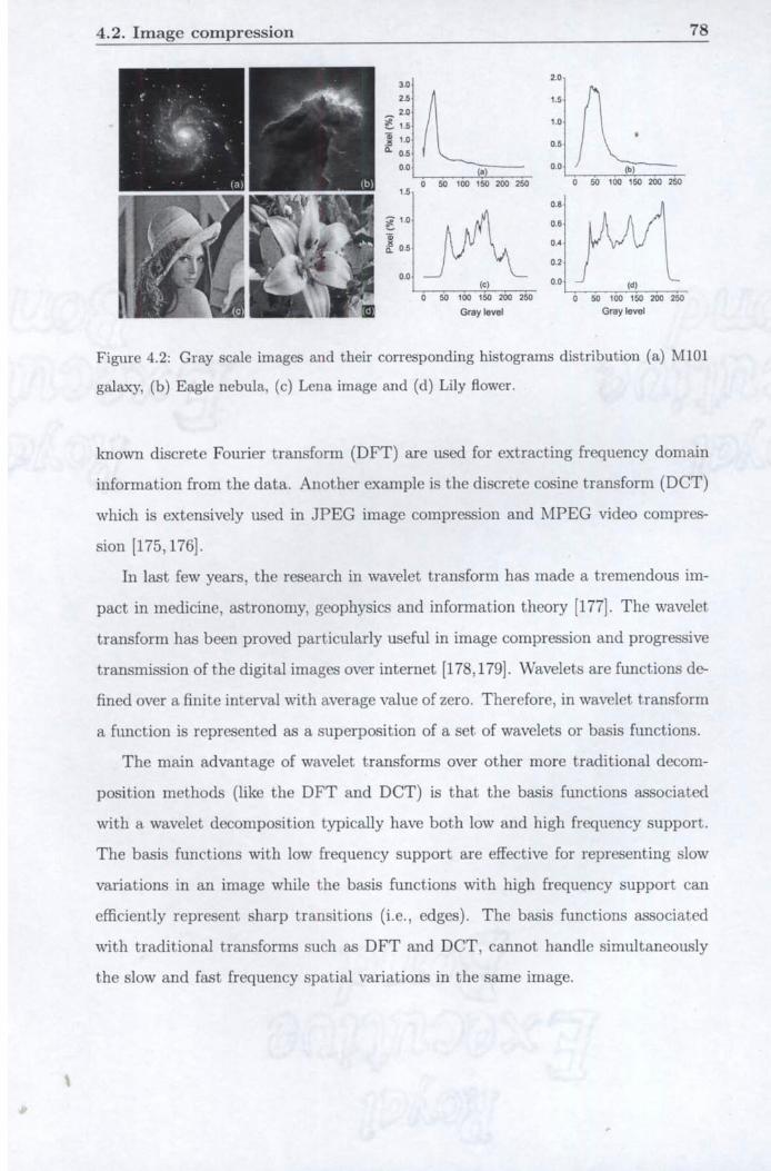
levels are more likely to occur t8han others. Wliicli means the histograms of most, of
the images are non-uniform. This is illustrated in Figure 4.2, where four different
images are shown along with their respect,ive hi~t~ograms. An image will contain a
coding redundancy if the grey levels are encoded in such a way t,hat uses more code
symbol or bits than absolutely necessary to represent a grey level. For exa.mple, a.
natura,l binary coding assigns fixed number of binasy bits to encode both the most
and the least probable grey levels. The coding redundancy can be overconle by
variable-length encoding, where, fewer number of bit,s are assigned to more probable
grey level values t>han the less probable ones. Huffman coding discussed in later
section, is an example of variable-length coding.
The human visual syst,em does not havc equal sensitivity for all the visual infor-
rnation in an image. Therefore, information t,hat are redundant for visual perception,
give rise to p.sychovisua1 redundancy. For example, human eye cannot, distinguish
between a 16-bit and a 24bit grey scale or colour irnage. The reduction of psycho-
visua.1 redundancy may result's in quantit,ative loss of information.
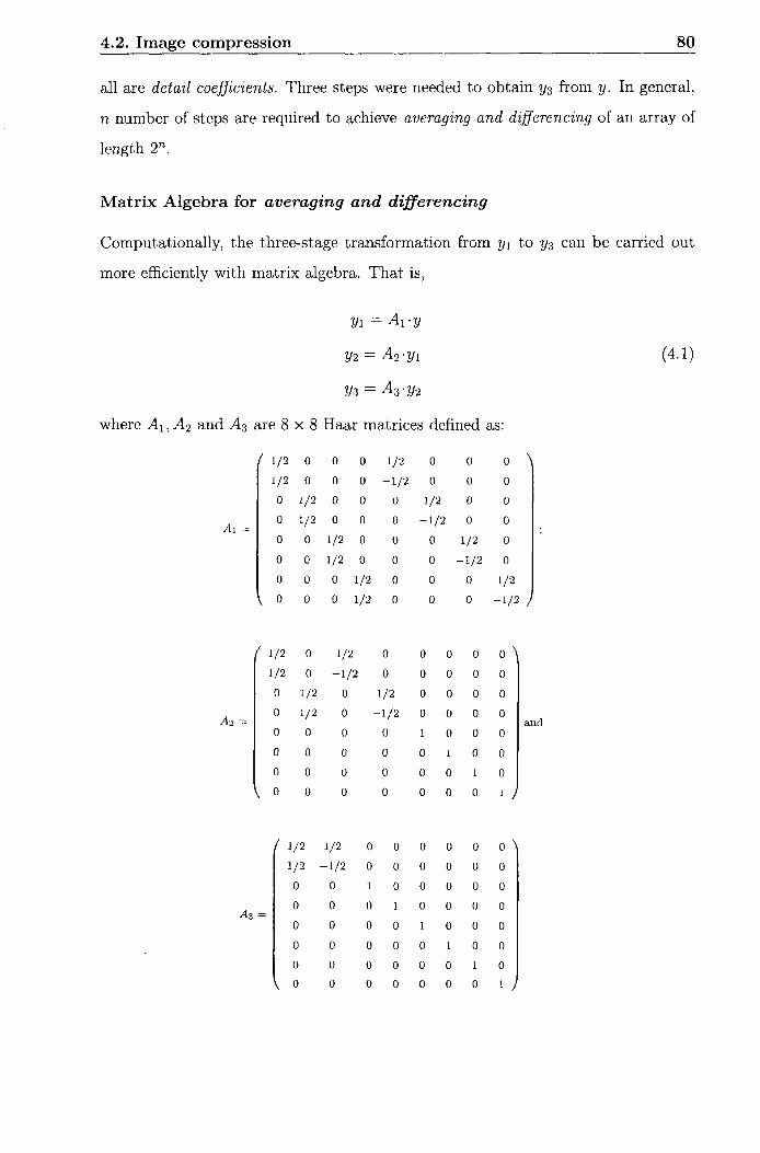
An image is represented as a 2-dimensional array of int,egers, each integer rep-
resenting the brightness level a t a given point. blathematical t8ransformat8ions ca.n
be applied to an image so as to obtain information that are not readily available
in the original image. There are several types of transfornlations. Most conlmollly
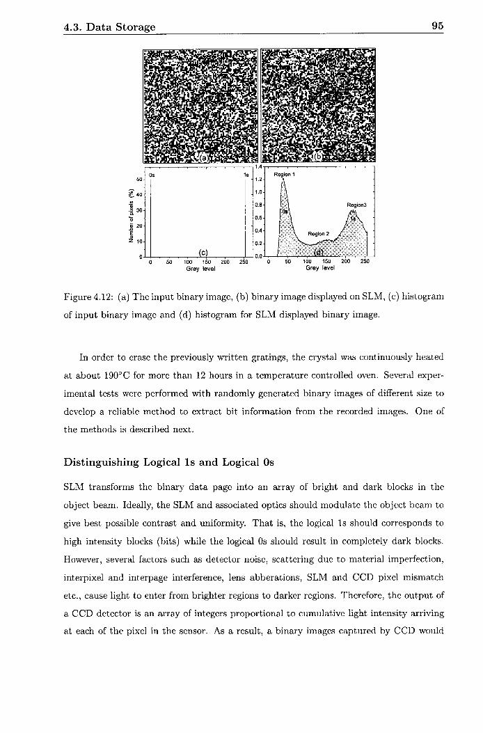
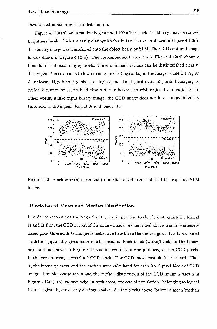
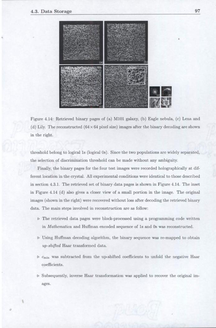
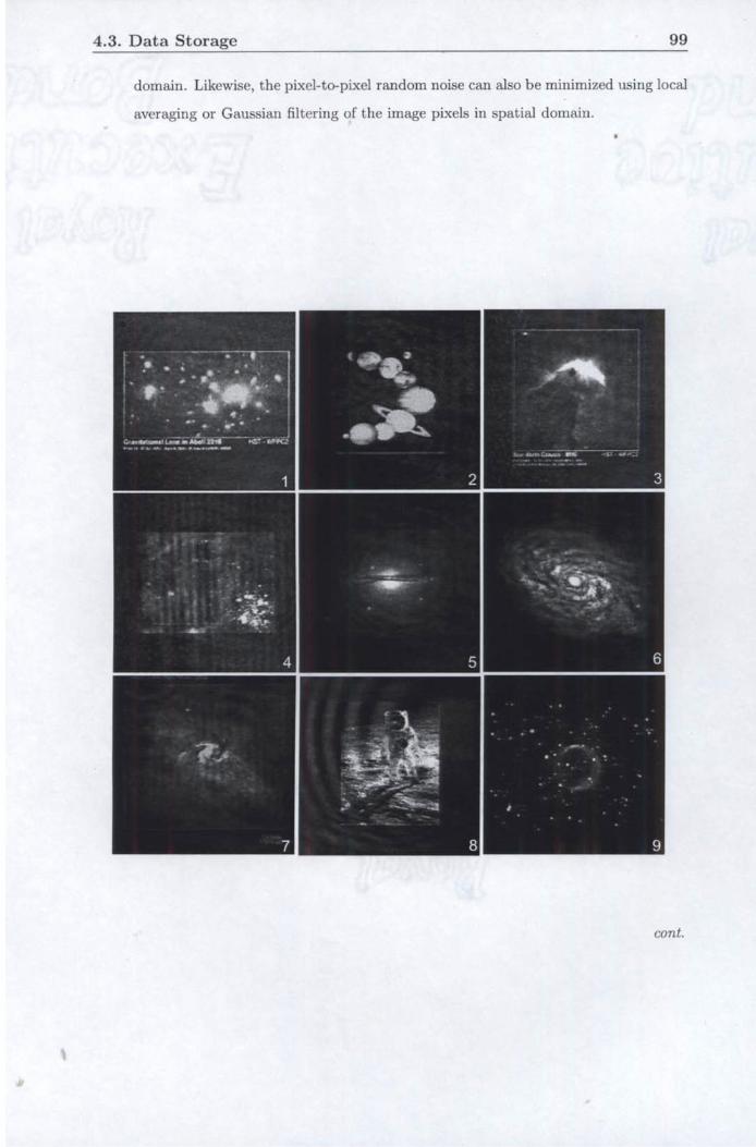
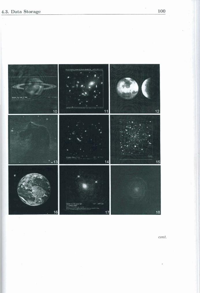
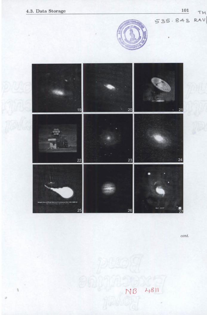
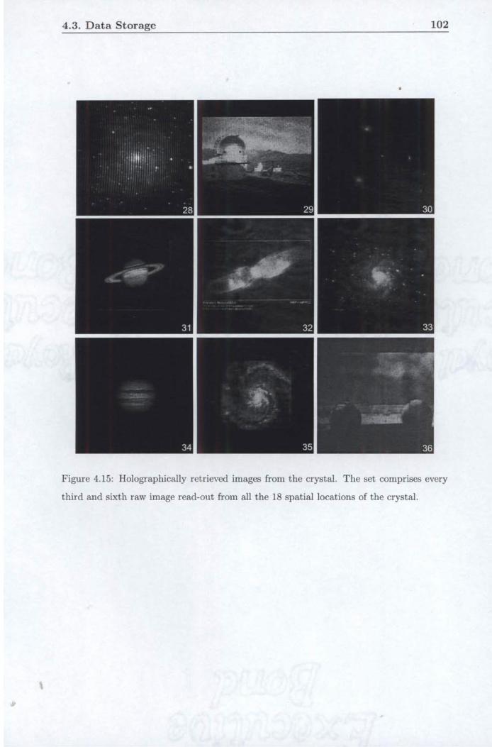
4.3. Data Storage 103
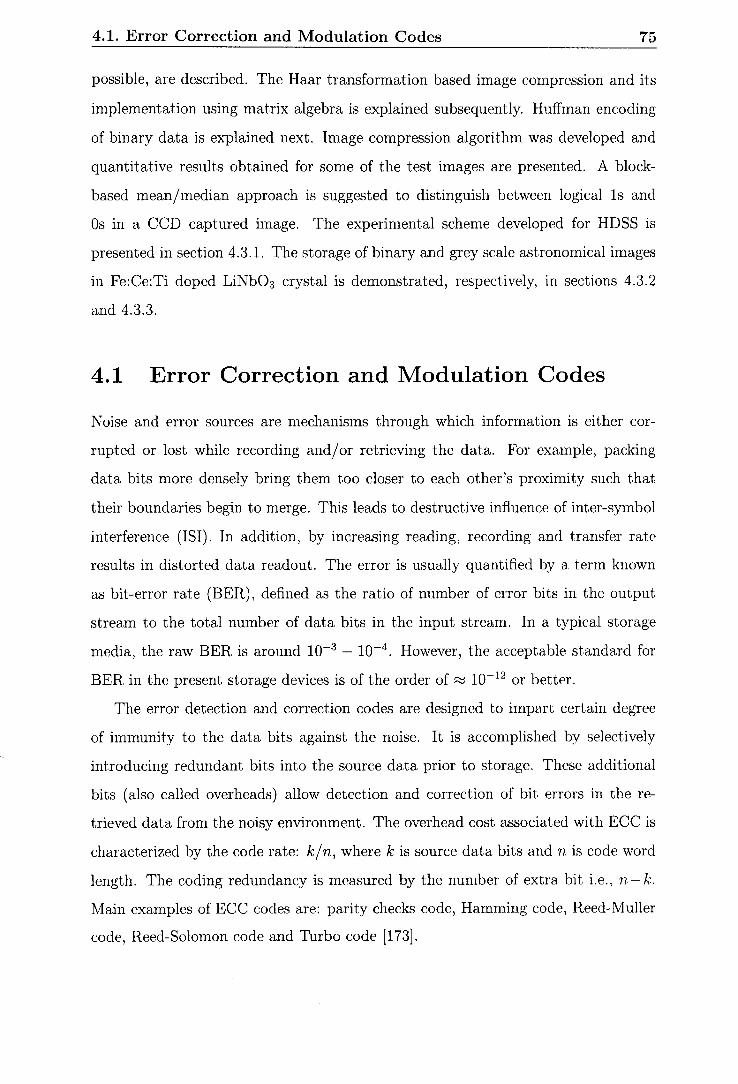
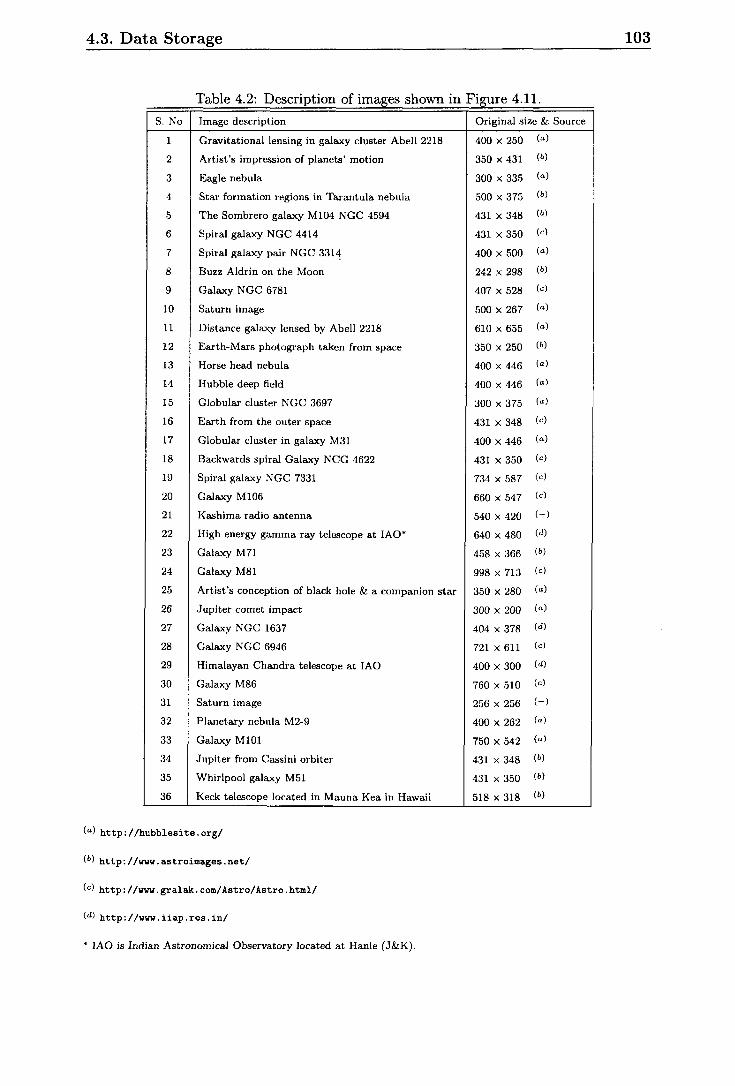
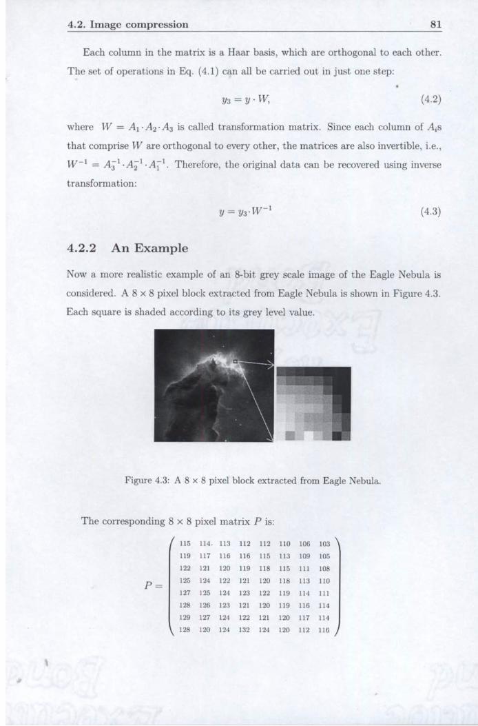
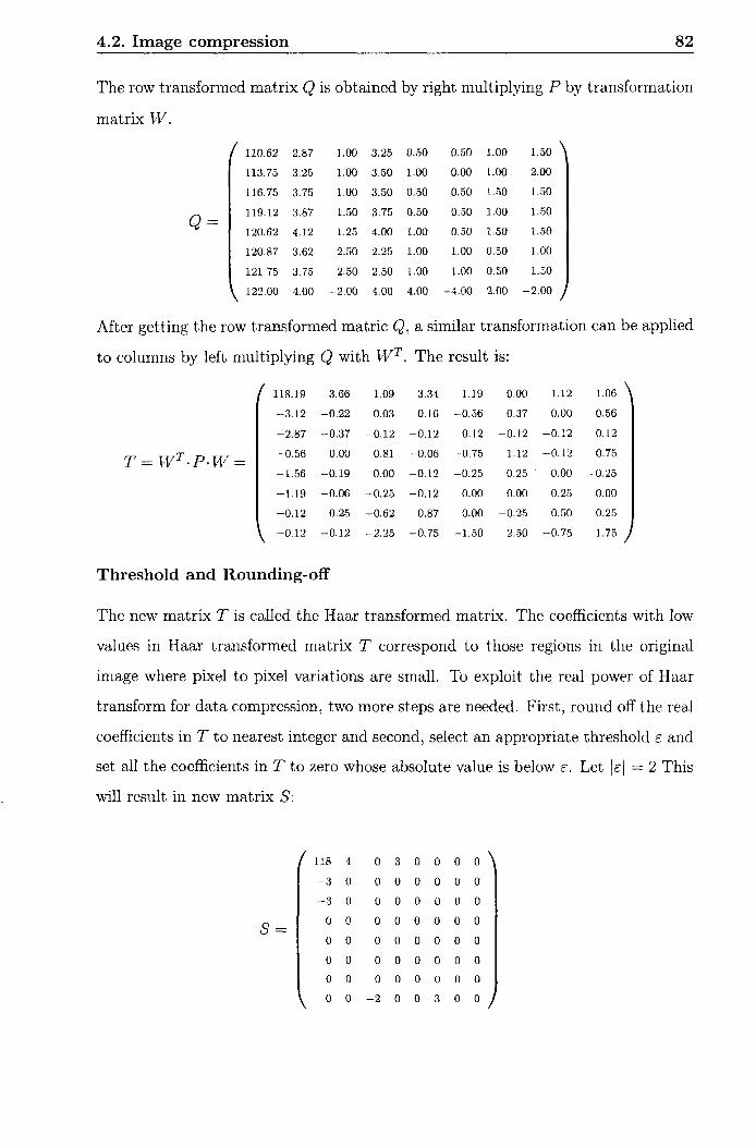
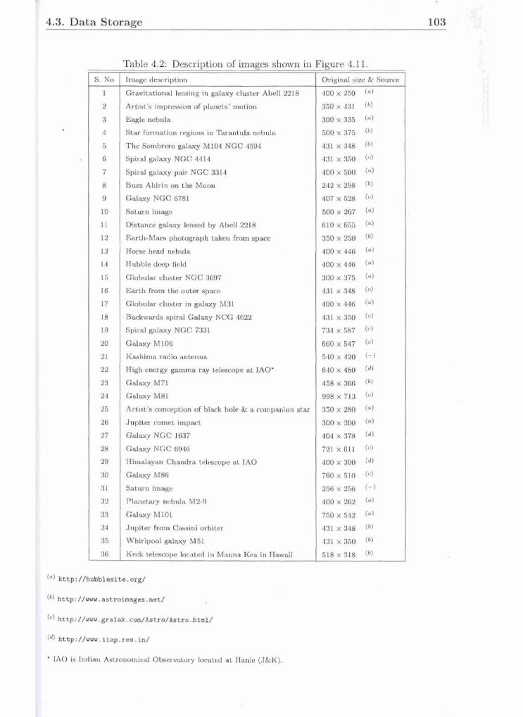
Table 4.2: Description of images shown in
S. No I Image description
Gravitational lensing in galaxy cluster Abell 2218
Artist's impression of planets' motion
Eagle nebula
Star formation regions in Tarantula nebula
The Sombrero galaxy M104 NGC 4594
Spiral galaxy NGC 4414
Spiral galaxy pair NGC 331?
Buzz Aldrin on the Moon
Galaxy NGC 6781
Saturn image
Distance galaxy lensed by Abell 2218
Earth-Mars photograph taken from space
Horse head nebula
Hubble deep field
Globular cluster NGC 3697
Earth from the outer space
Globular cluster in galaxy M31
Backwards spiral Galaxy NCG 4622
Spiral galaxy NGC 7331
Galaxy M106
Kashima radio antenna
High energy gamma ray telescope at IAO*
Galaxy M71
Galaxy M81
Artist's conception of black hole & a companion star
Jupiter comet impact
Galaxy NGC 1637
Galaxy NGC 6946
Himalayan Chandra telescope at IAO
Galaxy M86
Saturn image
Planetary nebula M2-9
Galaxy M101
( G ) ht tp : / /hubblesite . org/
34
35
36
( b ) http://vvv. astroimages .net /
Jupit,er from Cassini orbiter
Whirlpool galaxy M51
Keck telescope located in Mauna Kea in Hawaii
( C ) ht tp : //ww.gral&. com/Astro/Astro .html/
Figure 4.11.
Original size & Source
* IAO is Indian Astronomical Observatory located at Hanle (J&K).
4.3, Data Storage 103
w- SW fam&h r+xm In 'Egr-Cute nebula
~ g o m b r a r o ~ M 1 W N O C d W Splral gduy NGC 4414
8- g & ~ / pair NGC 3314
B w Aldrln en the Mowi
eartbMm3phata(paph*fmm- H ~ ~ w b u h Hubble deep Beid
G* dwkr NOC % r t h ~ & i m o u k r ~
Wbular clustar in gaky I431
~a&wm&rplrdGala*yNCG4=
Spiral & PlGC 7981
I Cdwy MI06
Jupfm sr lmprct
Gslaxy NGC 1637
Gelm POGC W61
Hlmhyan Chsadra bkcope st 1AO
4.4. Conclusion 104
4.4 Conclusion
In this chapter, a page oriented architecture of HDSS is outlined. The importance of
ECC and modulation codes in data storage application is briefly emphasized. In order to
counter the increased overhead rate due to ECC and modulation codes and to improve the
effective storage capacity, the need for image or data compression is highlighted. Three
types of redundancies used in data compression are discussed. Image compression using
the Haar wavelet transform is explained and the its implcrnentation using matrix algebra
is proposed. To remove the coding redundancy from t,he data, the variable length loss-
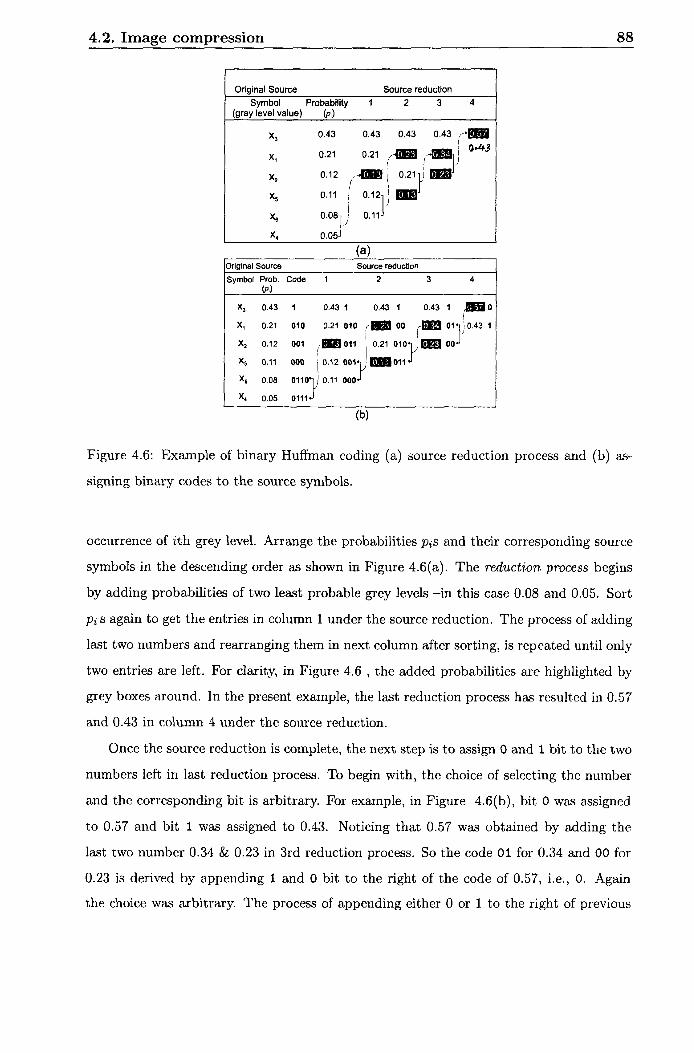
less encoding was described. Huffman's encoding technique was outlined with an example.
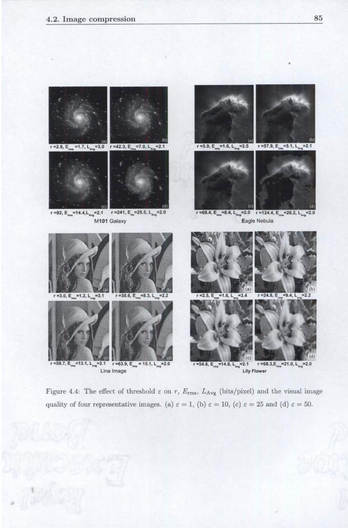
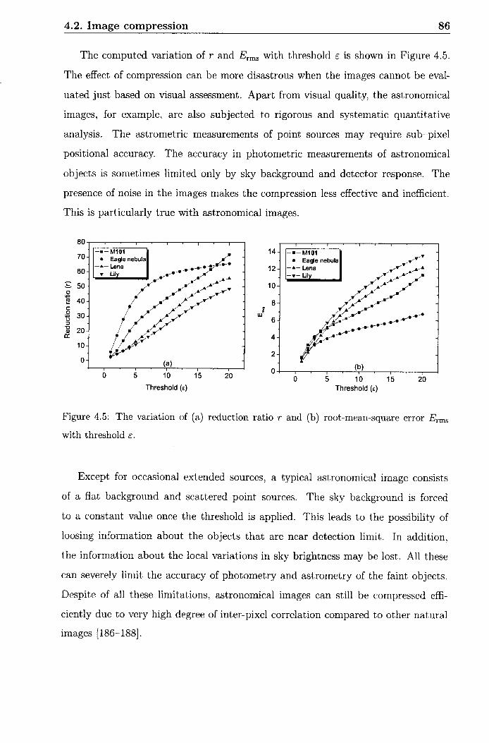
Sorne of the important parameters such as the degree of compression, the root-mean-square
error and the average code length were computed for the four test images.
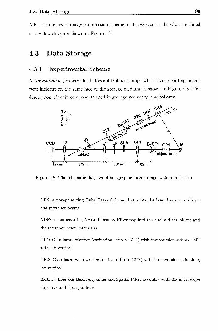
Experimental aspect of holographic data storage and retrieval system in the lab, were
explained in detail. A spatial arid rotation rnultiplexing scheme was developed to store
multiple image holograms in the photorefractive crystal. The storage and retrieval of
compressed binary data page was successfully implemented. A block-based mean arid
rnedian processing of CCD image was proposed to distinguish logical 1s and OS. The
compressed binary data pages corresponding to four test images were holographically
written in Fe:Ce:Ti LiNbOs. The stored data was retrieve and decoded to reconstruct the
original images. At the preliminary stage, holographic recording and retrieval of as many
as 108 grey scale astronomical images was successfully demonstrated. Finally, based on
the qualitative observations of the retrieved images few suggestions were made to improve