Honeycomb sandwich material modelling for dynamic simulations of a crash-box for a racing car
S. Boria & G. Forasassi Department of Mechanical, Nuclear and Production Engineering, Pisa University, Italy
Abstract
Aluminium sandwich construction has been recognized as a promising concept for structural purposes in lightweight transportation systems. The aim of the present study is to investigate, through experiment as well as numerical approaches, the energy absorbing capabilities of a thin-walled crash-box, made of sandwich material, for a racing car. The basic considered structures are panels composed of two aluminium alloy sheets and an aluminium hexagonal cells honeycomb core. Several crash tests were performed, in the conditions related to a frontal impact at the velocity of 12 m/s, in order to acquire information on the dynamic behaviour of the mentioned structure; during these tests the load-deformation diagram, the deceleration and the energy absorbed by the structure were measured. A finite element model is then developed using the non-linear, explicit dynamic code LS-DYNA. In order to characterize the material and to set up the numerical model, a series of strength tests were carried out on aluminium honeycomb-cored sandwich panel specimens. By means of these preliminary tests some necessary material parameters were determined. The simulation results accurately predicted the average deceleration, the specific absorbed energy and the total deformation of the specimen, but appeared to slightly overestimate the initial peak load obtained in the crash tests. Therefore the performed investigation can help to build confidence in the future possibility of using non-linear dynamic finite element code LS-DYNA for the design of sandwich primary structures subjected to crash loading, especially after a further tuning up of the models and material characteristics. Keywords: aluminium sandwich panel, LS-DYNA, dynamic simulation, plastic collapse.
Some of the more important design considerations for automobile crashworthiness are energy absorption optimization, weight reduction and manufacturability. The energy absorption capability of an exposed crashworthy element or system is greatly affected by its structural design and material properties [1]. Recently, a tendency for constructing sandwich structures seems to be of great importance for crashworthiness problems from an energy absorbing efficiency and increased safety point of view [2], especially when high performance vehicles are concerned. In order to investigate the dynamic behaviour of a crash-box for a racing car, numerical simulations with the commercial explicit finite element code LS-DYNA [3] were used in addition to dynamic testing. The considered crash-box design foresees a lightweight sandwich structure (Fig. 1), that is a special kind of composite structure with a lightweight honeycomb core separating two thin and stiff sheets in order to increase the second moment of inertia and therefore the bending stiffness. The external sheets primarily carry the in plane tensile and compressive loads due to bending, while the core resists to bending related transverse and shear loads [4].
Figure 1: Honeycomb sandwich structure.
Figure 2: Sandwich structure failure modes [4].
A variety of failure modes can occur in sandwich structures depending on the type of load, the constituent materials and clamping conditions (Fig. 2). The orthotropy and the inhomogeneity as well as the number of failure modes make the analysis of honeycomb sandwich structures no trivial task. Different
approaches for modelling sandwich structures by the FE method exist, which differ in modelling, computational cost and accuracy of the results and their adoption depends on the specific model size and loading case. A detailed representation of the hexagonal cells with shell elements (Fig. 3b) can predict the cell wall deformation for impact simulations reasonably well, but it is unsuitable for large scale models due to the computational cost and time required. A possible simplification may consist of representing the cellular core as a homogeneous continuum using the honeycomb structure’s effective orthotropic material parameters (Fig. 3c). Solid elements for the honeycomb core and for the sandwich faces were used in [5,6]. In this case the small face thickness leads to a very small element edge length. In [7,8], the faces were modelled with shell elements instead. A further simplification allows for the representation of the whole sandwich structure with shell elements, in which the faces and core are defined as separate layers [9,10]. However, most of these 2D modelling approaches are unable to account for the major sandwich failure modes. Since the main goal of the presently discussed dynamic simulation of the crash-box is the consideration of the most part of the failure modes, a three-dimensional modelling approach with solid elements for the core and shell elements for the face sheets was adopted.
Figure 3: Different models for the cellular core: a) real, b) detailed cell wall modelling, c) modelling with solid elements.
2 Material models
2.1 External aluminium face sheets
For the aluminium external sheets material #24 (*MAT_PIECEWISE_LINEAR _PLASTICITY) of the LS-DYNA material model library was used with shell elements. The nonlinear behaviour was simulated according to the Cooper-Symonds law, considering the aluminium deformation rate sensitivity. The sought after absorbing material mechanical characteristics were simulated by means of a bi-linear curve characterized by variable yield strength and strain hardening. The thickness of each aluminium sheet is 1.5 mm.
2.2 Honeycomb core
The honeycomb core considered in the present paper is produced by the lateral expansion of thin sheets partially bonded to one another in a stripe pattern, thus it
is composed of hexagonal cell walls with single and double foils. The foil material used in the experiment is an aluminium alloy (A5052). The cell size is 1/4 in (6.35 mm), which is the distance between the opposite sides of the cell. The foil thickness is 0.002 in (0.0503 mm). The density of the aluminium honeycomb is 68.8 kg/m3 and its height is 12 mm. In the analysis, for the sake of simplification, the cellular honeycomb core structure is treated as a homogeneous material using its effective orthotropic material properties. The honeycomb material directions are defined as the L-direction (ribbon direction), W-direction (direction perpendicular to the ribbon) and the T-direction (thickness direction) (Fig. 4).
Figure 4: Honeycomb material directions.
For the honeycomb core LS-DYNA material model #26 (*MAT_HONEYCOMB) was used in combination with the fully integrated solid element type. In this orthotropic material model nonlinear elasto-plastic constitutive behaviour based on experimentally determined stress-strain curves can be defined separately for all normal and shear stresses. But since test series on honeycomb material normally require a rather large amount of time and cost associated with specimen preparation and setting up testing devices, an alternative way of determining these nonlinear effective mechanical properties was investigated in the present research activity. The development of FE-models of core structures and the performance of compression and shear test simulations allow for the efficient determination of the stress-strain data, which is the input for MAT #26. To this purpose a minimum of experimental data is solely necessary for the validation of this type of model. The simplest way to get a first impression of the material behaviour is by quasi-static compression in T-direction. Block samples (70 x 70 mm2) were compressed at constant, low velocity. Fig. 5 shows the schematic view of the crushing test under lateral pressure and the experimental one. The test specimen is put on the rigid floor and a rigid plate is pushed down by a loading actuator. Fig. 6 shows the load versus indentation curves obtained for the test specimen. After the maximum load is reached rather quickly, the panel resistance decreases rapidly because the walls of the core cell are partly folded. Physically, the material forms a number of local wrinkle sites and begins to deform in a concertina fashion. With a further increase in the deformation, the reaction force increases again if the folded walls come in contact with the adjacent ones. This type of response behaviour appears repeatedly until the walls of honeycomb core cell are completely folded (70-80% of compression); after this point the material thickens and the reaction force increase rapidly.
Figure 5: Quasi-static compression test in T-direction.
Figure 6: Load versus deformation curve of the crushing test specimen.
Figure 7: Investigation of the influence of mesh size.
Models of the core structure were generated with shell elements of the Belytschko-Tsay type, according to the specified geometric data (Fig. 3b). The influence of mesh size on the structure’s effective properties was investigated in compression test simulations. The mesh size influences the ability of the representing cell wall buckling in an accurate manner. Therefore, a coarse mesh was impracticable. Very fine meshed led to huge computational time and possible numerical instabilities; for this reason the mesh size represented in the middle part of Fig. 7 was finally chosen, for which the calculated stress levels differed only marginally from the finer mesh case. Besides the mesh size of the model, the cell wall thickness and material properties have the major influence on the structural behaviour of the core. After the parameters of the cell wall (thickness, Young’s modulus and yield strength) were determined and validated against experimental compression and transverse shear data of the core manufacturer, complete quasi-static material testing simulations were performed for compression, tension and shear in all material directions.
3 Strength tests of aluminium honeycomb sandwich panels
After developing the material models for sandwich faces and the core, experiments on sandwich components were performed in order to verify the reliability of the material models. To investigate the structural failure characteristics mentioned above, two types of experiments, namely three point bending tests and buckling under (in plane) axial compression, were carried out in the present study using aluminium sandwich specimens with a thickness of 15 mm.
3.1 Three point bending tests
To investigate the characteristics of bending behaviour of aluminium honeycomb sandwich panels and also to analyze the shear effects of honeycomb core, three point bending tests are carried out (Fig. 8). Three specimens with the same characteristic were tested in bending. The experiments were carried out with a loading speed of about 0.05 mm/s using a 100 kN loading actuator system. The data sets relating the loads and the mid-span deflection of the panel specimen are automatically detected and directly recorded on to the hard disk of the computer in real time as the stroke of the actuator advances (Fig. 9a). The linear elastic behaviour is evident until the peak load; with a further increase in applied loads, plastic failure occurs at the honeycomb cell under the central indenter. Fig. 9b shows the deformed shape of the specimen after testing with a significant local deformation at the load point. The performed LS-DYNA simulations led to a corresponding representation of the core failure.
Figure 8: Schematic view of the three point bending test set-up.
Figure 9: a) Load-deflection curve, b) deformed shape.
3.2 Buckling and ultimate collapse tests under axial compression
Several formulations for strength predictions of steel plates have been suggested in the past with reasonable accuracy. On the other hand, similar research work on the buckling of aluminium sandwich panels is limited. Four specimens are tested. The test set-up is designed so that the boundary conditions of the specimen are constrained along their two sides. Edgewise compression tests are used for the evaluation of sandwich failure modes under in-plane compression. The tests are conducted in two different directions (L and W). No large difference in strength between the two cases was detected. The sandwich panels failed in a shear crimping or in a face wrinkling mode; both failure modes could be represented rather satisfactorily in the corresponding LS-DYNA simulations (Figs. 10, 11).
Figure 10: Edgewise compression test of the sandwich: shear crimping failure.
Figure 11: Edgewise compression test of the sandwich: face wrinkling failure.
4 Dynamic simulations of a crash-box for a racing car
The survivability of a driver in an accident is achieved by a combination of the crash resistance of the car and its ability to absorb energy. This has been achieved by providing a survival cell (the chassis), which is extremely resistant to damage, around which energy absorbing devices are placed at strategic points on the vehicle. The energy absorbing devices operate to enable maximum deformation up to a specified limit. The devices used are designed to dissipate energy irreversibly during the impact, thereby reducing the force and momentum transferred to the survival cell and hence the driver. Since the late 1980s FIA has introduced a series of regulations to ensure that the cars conform to stringent safety requirements and build quality. Each vehicle must satisfy a list of requirements, in the form of officially witnessed tests,
before it is allowed to race. There are two groups of tests that must be passed for a frontal absorbing structure of a CN2 prototype. The first is a static side load applied on a vertical and transversal plane passing 500 mm forward of the front wheel axle. A constant load of 2000 daN must be applied to one side of the crash-box using a pad. After 30 seconds of application, there must be no failure of the structure or of any attachment between the crash-box and the chassis. The second test defines the effectiveness of the energy absorbing structure. The crash-box and the front part of the survival cell must be subjected to an impact test against a solid, vertical barrier. The front part of the chassis to be tested must be solidly attached to a trolley. The total weight of the trolley and test structures must be of 610 Kg and the velocity of impact of 12 m/s. During the test the maximum average deceleration of the trolley must not exceed 25 g and the final deformation must be contained in the zone situated more than 100 mm ahead of the driver’s feet. In the framework of the presently discussed research activity, actual prototype manufacturing and testing of each configuration would be too expensive in cost and time. For these reasons, numerical FE models have been developed to predict the structural behaviour under dynamic loads. The finite element simulation of the mentioned structure was performed in the usual three typical steps: building of a parametric model by means of the pre-processor ANSYS, non-linear dynamic analysis with LS-DYNA and post-processing using ANSYS for the interpretation and visualization of the results.
Figure 12: Total system: a) scheme, b) numerical model.
The total system was simulated by the right combination of a crash-box and a striking mass that impact a barrier (Fig. 12). In the previously mentioned analysis, the material characteristics resulting from the sandwich component test were incorporated into the FE models of the crash-box (Fig. 13). The barrier and the moving mass were simulated with the element type SOLID 164 and were also considered as rigid bodies. The contact interface type ‘nodes-to-surface’ is used for the contact between the rigid barrier and the crash-box during the impact. This interface type is selected in order to prevent penetration of the specimen’s internal nodes in contact with the rigid plate during the simulation procedure. In order to prevent sliding at the proximal ends, a coefficient of friction of 0.25 was incorporated between the rigid body surface and the edges of the structure. Moreover any self-contacts of the inner and the outer surfaces of the crash-box are assumed frictionless. The boundary
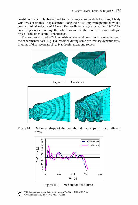
condition refers to the barrier and to the moving mass modelled as a rigid body with five constraints. Displacements along the z axis only were permitted with a constant initial velocity of 12 m/s. The nonlinear analysis using the LS-DYNA code is performed setting the total duration of the modelled axial collapse process and other control’s parameters. The mentioned LS-DYNA simulation results showed good agreement with the experimental data (Fig. 15), recorded during some preliminary dynamic tests, in terms of displacements (Fig. 14), decelerations and forces.
Figure 13: Crash-box.
Figure 14: Deformed shape of the crash-box during impact in two different
A shell-solid-shell modelling approach with 2D-elements for the faces and 3D-elements for the core has shown to be the best compromise between computational cost and the ability to represent most of the failure modes of the impact absorbing structure considered. Moreover a different approach was used for the determination of honeycomb material properties; this technique was presented as a time- and cost-efficient alternative to very extensive testing needed for a “design by test” approach. As it was foreseen, the numerical determination of the effective properties of sandwich core structures by virtual testing (numerical analyses and few experimental tests) turned out to be a promising method, which may be adopted for simulations of sandwich component tests and for frontal impact analysis of a crash-box for a racing car.
References
[1] Mamalis, A.G., Manolakos, D.E. & Viegelahn, G.L., Deformation Characteristics of Crashworthy Components, Fortschritt-Berichte der VDI-Zeitschriften, Reihe 18, Nr. 62, Düsseldorf, 1989.
[2] Goldsmith, W. & Sackman, J., Energy absorption by sandwich plates: a topic in crashworthiness, Crashworthiness and Occupant Protection in Transportation Systems, AMD-vol. 126/BED-vol. 19, ASME, 1991.
[6] Shipsha, A., Zenkert, D., Compression after impact strength of sandwich panels with core crushing damage, Applied Composite Materials, 12, pp. 149–164, 2005.
[7] Kerth, S., Maier, M., Nohr, M., Numerical simulation of the crash behaviour of sandwich structures with fibre reinforced polymer-faces, Proc. Of 29th ISATA, Road and Vehicle Safety, International symposium on automotive technology and automation, Florence, Italy, pp.387–394,1996.
[8] Aktay, L., Johnson, A.F., Holzapfel, M., Prediction of impact damage on sandwich composite panels, Computational Materials Science, 32, pp. 252–260, 2005.
[9] Noor, A.K., Burton, W.S., Bert, C.W., Computational models for sandwich panels and shells, Applied Mechanics Reviews, 49, pp. 155–199, 1996.
[10] Torre, L., Kenny, J.M., Impact testing and simulation of composite sandwich structures for civil transportation, Composite Structures, 50, pp. 257–267, 2000.