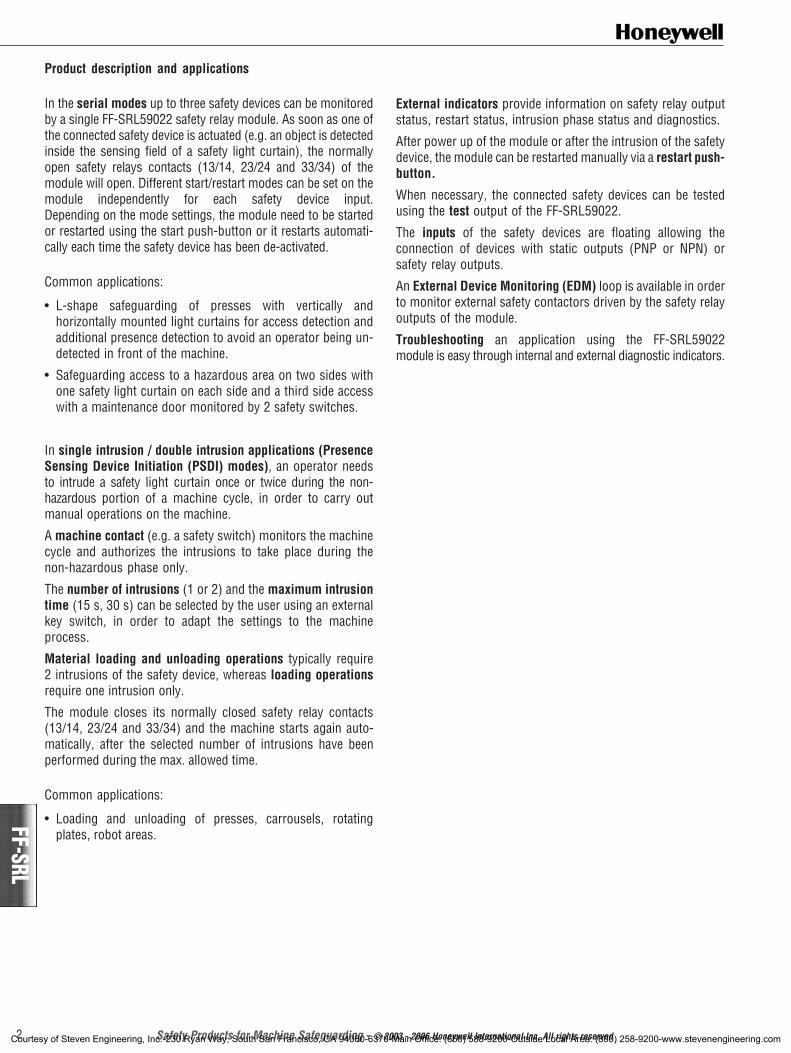
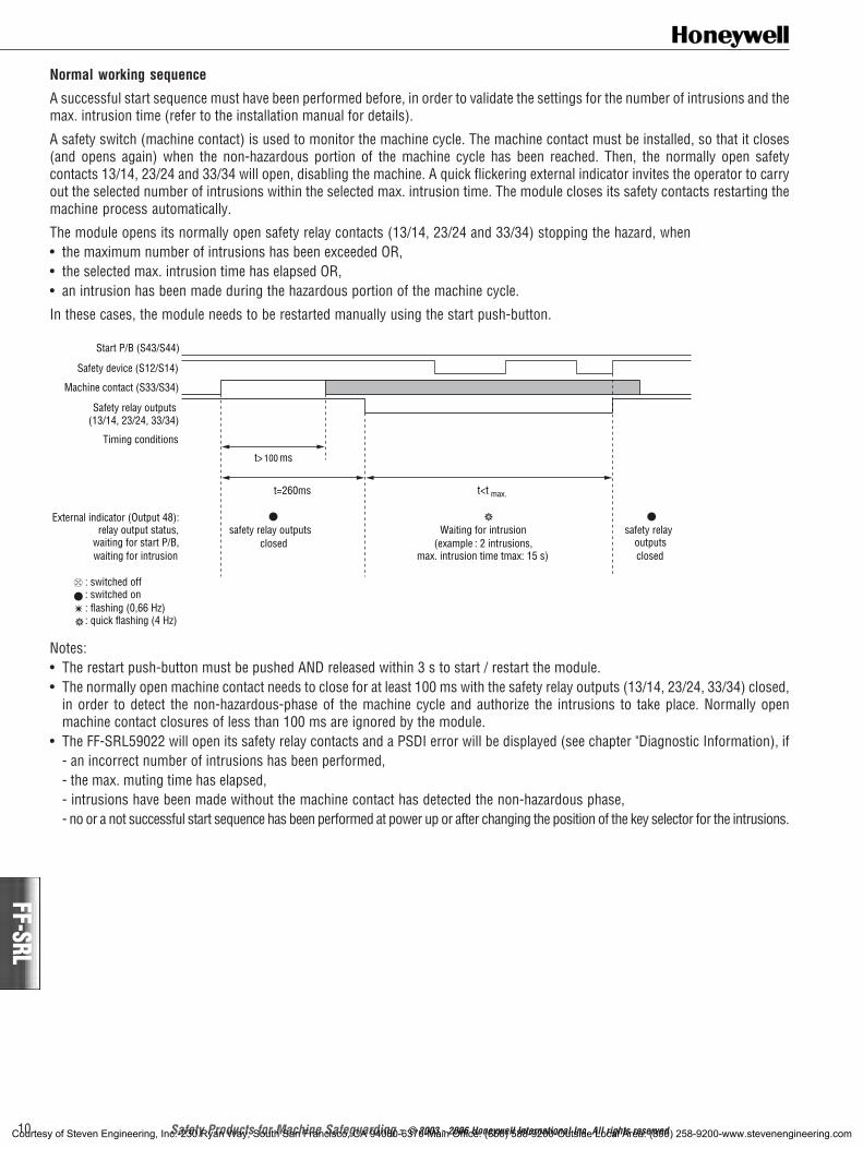
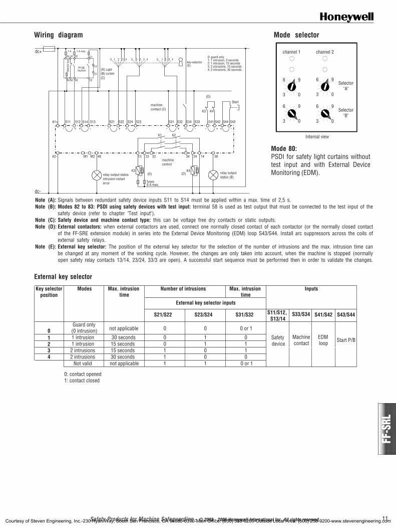
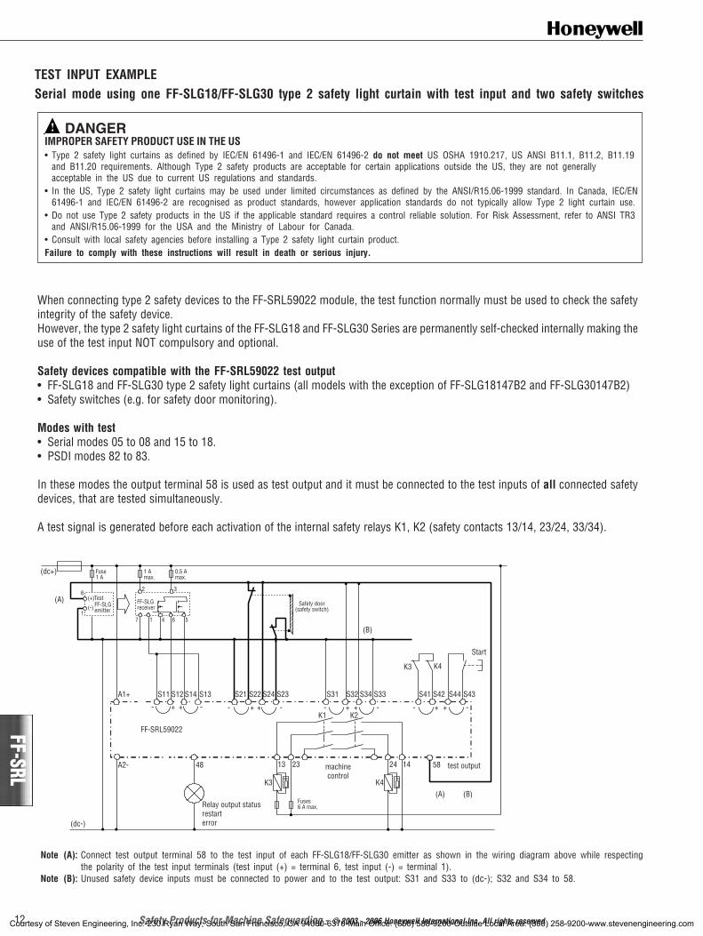
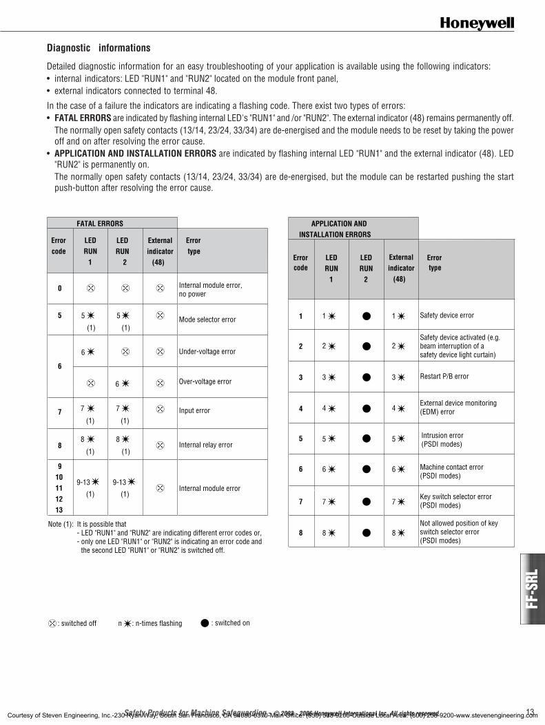
Standstill and Low Speed Monitor• Standstill monitor / low speed
monitor for any kind of rotatingdevices
• Used to unlock a safety doorguarding a rotating machine onlywhen the hazardous movement isstopped
• Used to activate an emergencybrake when an e-stop signal isreceived and while the motion isstill present
FF-SR05932
45 mm x 121 mm x 74 mm /1.77 in x 4.76 in x 2.91 in
FF-SR05936
Front view
Standstill Monitor• Standstill detection of induction
motors• Used to unlock a safety door
guarding a rotating machine onlywhen the hazardous movement isstopped
• Used to activate an emergencybrake when a e-stop signal isreceived and while the motion isstill present.
FF-S
RT
45 mm x 121 mm x 74 mm /1.77 in x 4.76 in x 2.91 in
FF-SRT
Front viewTime Delay Module
• Time delay before disconnectionof safety interface circuits
Safety Control Modules for Machine Interfacing
FF-SRST
FF-S
RSTEmergency Stop Module with
Timer• Time delay before disconnection
of safety interface circuits• Door protection: delayed opening
of an interlocked protective gate
45 mm x 121 mm x 74 mm /1.77 in x 4.76 in x 2.91 in
Front view
Front view
45 mm x 121 mm x 74 mm /1.77 in x 4.76 in x 2.91 in
FF-S
R059
32FF
-SR0
5936
CATEGORY 1per EN 954-1
Suitable for interfacesup to
According toMachinery Directive98/37/EC andIEC/EN 60204
CATEGORY 1per EN 954-1
Suitable for interfacesup to
(Pending)
CATEGORY 4per EN 954-1
Suitable for interfacesup to
Category 3per EN 954-1
Suitable for interfaces up to
(direct safety contacts)
(delayed safety contacts)
Category 3per EN 954-1
Suitable for interfaces up to
(Pending)
According to MachineryDirective 98/37/CE andIEC/EN 60204
® The overall safety category depends on the category of the main safety control module, therefore a higher safety category may be reached. ¯ Direct contacts Ä Delayed contacts
n 3 x 10⁶ IP 20 24 Vdc n
120 Vac230 Vac
® 1 1 or 2 1 NO 8 A
1 NC
15 ms ± n n n n n n n 106 IP 20 24 Vac/dc n n
Ä 4 2 2 NO 5 A
1 NC
¯ ¯
3 Ä
® 1 1 2 NO 8 A
2 NC
® 3 2 2 NO 4 A
1 NC
2 s n n n n 106 IP 20 24 Vdc n
120 Vac230 Vac
± Broken wire detection in measuring inputs
3,2 ms / 8,3 s n n n 106 0,5 s IP 20 24 Vac/dc n n
120 Vac230 Vac
According to MachineryDirective 98/37/EC andIEC/EN 60204
Relay Control Modules to be used with ESPE equipment
FF-S
RS59
392
FF-SRS59392
FF-S
RL59
252
FF-SRL59252
FF-SRL59192
FF-S
RL59
192
Dual channel control module (for ESPE with static safety outputs)
Compatible with Honeywell ESPEFF-SYA, FF-SG, FF-SLG Series
Dual channel control module (for ESPE with static safety outputs)
Compatible with Honeywell ESPEFF-SYA, FF-SG, FF-SLG Series
Dual channel control module (for ESPE with static safety outputs)
Compatible with Honeywell ESPEFF-SYA, FF-SG, FF-SLG Series
CATEGORY 4per EN 954-1
Suitable for interfacesup to
CATEGORY 4per EN 954-1
Suitable for interfacesup to
(Pending)
CATEGORY 4per EN 954-1
Suitable for interfacesup to
(pending)
(pending)
®
C US
(pending)
45 mm x 121 mm x 74 mm /1.77 in x 4.76 in x 2.91 in
Front view
45 mm x 118 mm x 84 mm /1.77 in x 4.64 in x 3.30 in
22,5 mm x 118 mm x 84 mm /0.89 in x 4.65 in x 3.31 in
Front view
Front view
Powe
r sta
tus
indica
tor
Outpu
ts sta
tus in
dicato
rCr
oss-
fault
detec
tion
Typic
al ele
ctrica
l life
span
Sim
ultan
eity
of
2
input
cha
nnels
Seali
ng
Volta
ge
Inpu
t ch
anne
ls
Categ
ory
per
EN 9
54-1
Safet
y co
ntac
ts
• Safety Products for Machine Safeguarding •28 29• Safety Products for Machine Safeguarding •
45 mm x 121 mm x 74 mm /1.77 in x 4.76 in x 2.91 in
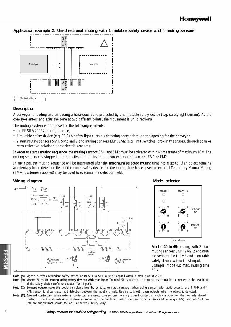
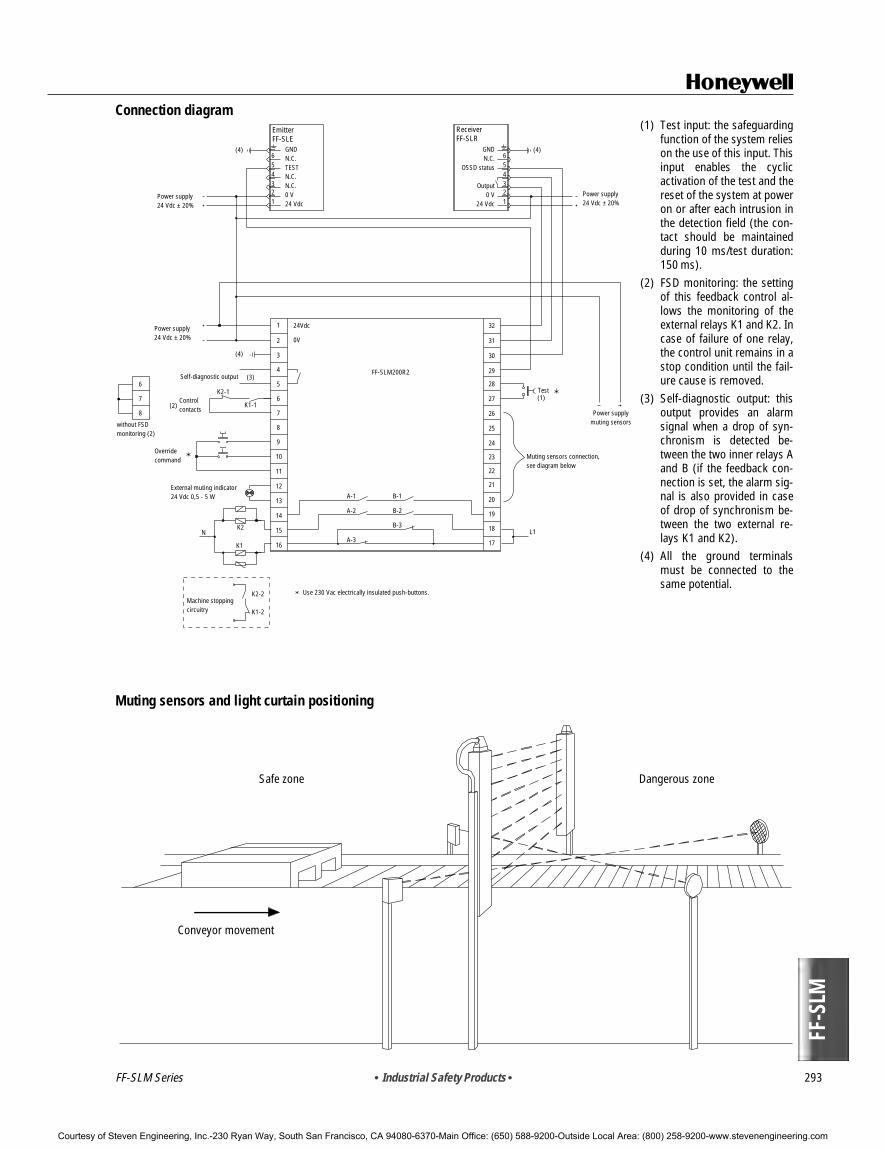
Category 4 Muting for Conveyor orMachine Applications
Compatible with any Honeywell Type 2,Type 3 or Type 4 electrosensitiveprotective equipment*Accept one muted safety device andone auxiliary safety device (muted ornon muted)*with some restrictions (see productinstallation manual)
®
C US
CATEGORY 4per EN 954-1
Suitable for interfacesup to
4 2 x 2 n 3 NO 5 A 24 Vdc
(pending)
Front viewNew
TYPICAL APPLICATIONS APPROVALS DIMENSIONS
! WARNINGMISUSE OF DOCUMENTATION• The information presented in this product sheet (or catalogue) is for reference only. DO NOT USE this document as system
installation information.• Complete installation, operation and maintenance information is provided in the instructions supplied with each product.
Failure to comply with these instructions could result in death or serious injury.
FF-S
RS59
24
• Industrial Safety Products • 239
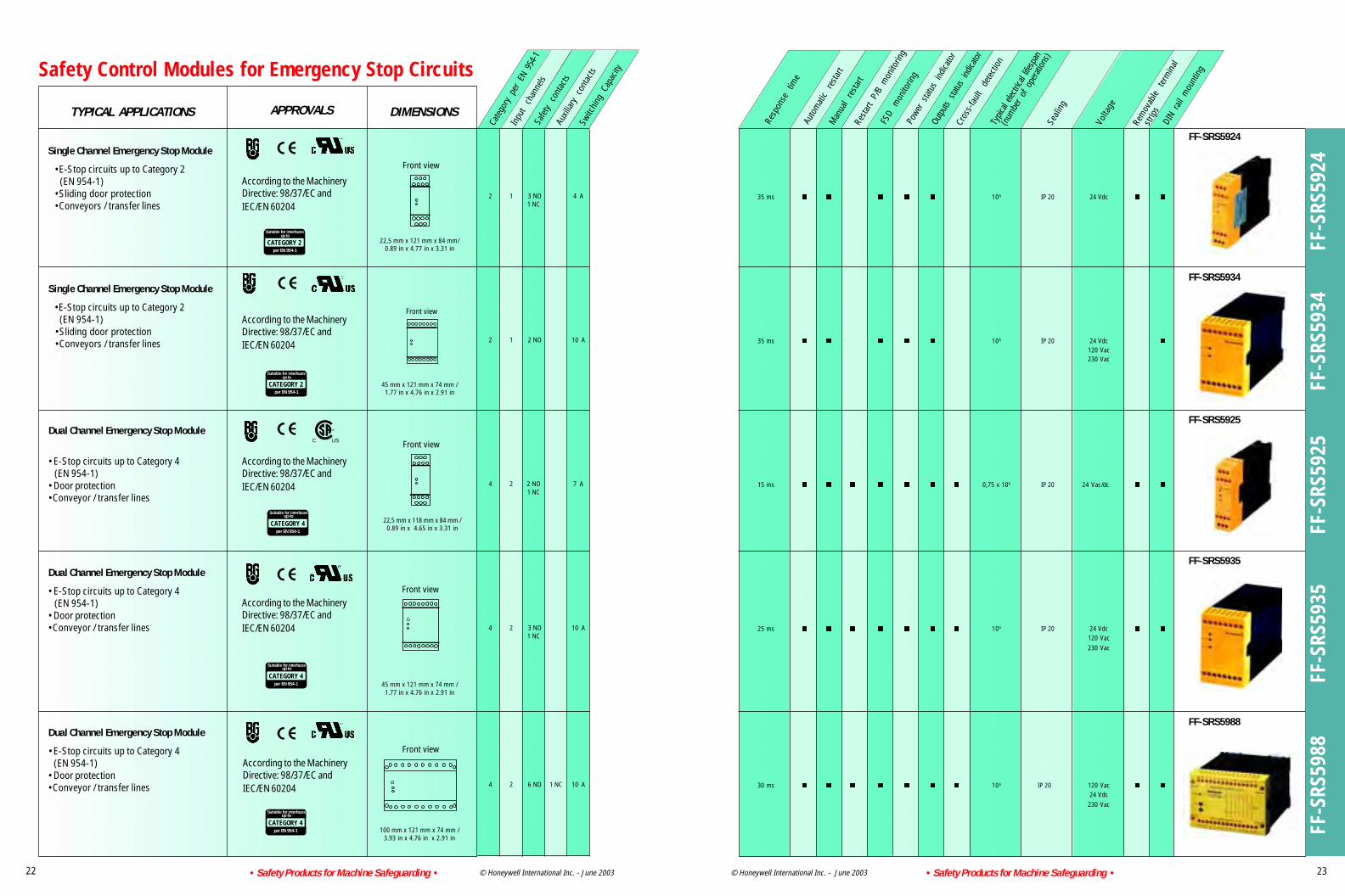
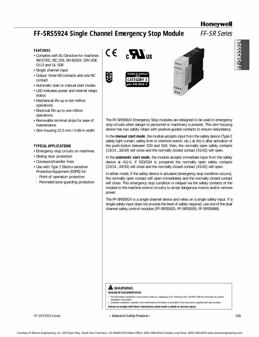
The FF-SRS5924 Emergency Stop modules are designed to be used in emergencystop circuits when danger to personnel or machinery is present. This slim housingdevice has two safety relays with positive-guided contacts to ensure redundancy.
In the manual start mode, the module accepts input from the safety device (Type 2safety light curtain, safety limit or interlock switch, etc.) at A1(+) after activation ofthe push-button between S33 and S34; then, the normally open safety contacts(13/14...33/34) will close and the normally closed contact (41/42) will open.
In the automatic start mode, the module accepts immediate input from the safetydevice at A1(+); if S33/S34 is jumpered the normally open safety contacts(13/14...33/34) will close and the normally closed contact (41/42) will open.
In either mode, if the safety device is actuated (emergency stop condition occurs),the normally open contact will open immediately and the normally closed contactwill close. This emergency stop condition is relayed via the safety contacts of themodule to the machine control circuitry to arrest dangerous motion and/or removepower.
The FF-SRS5924 is a single channel device and relies on a single safety input. If asingle safety input does not provide the level of safety required, use one of the dualchannel safety control modules (FF-SRS5925, FF-SRS5935, FF-SRS5988).
CATEGORY 2per EN 954-1
Suitable for interfacesup to
FF-SR Series
FEATURES• Complies with EU Directive for machines
98/37/EC, IEC 204, EN 60204, DIN VDE0113 and UL 508
• Single channel input• Output: three NO contacts and one NC
contact• Automatic start or manual start modes• LED indicates power and internal relays
status• Mechanical life up to ten million
operations• Electrical life up to one million
operations• Removable terminal strips for ease of
maintenance• Slim housing 22,5 mm / 0.89 in width
TYPICAL APPLICATIONS• Emergency stop circuits on machines• Sliding door protection• Conveyors/transfer lines• Use with Type 2 Electro-sensitive
Courtesy of Steven Engineering, Inc.-230 Ryan Way, South San Francisco, CA 94080-6370-Main Office: (650) 588-9200-Outside Local Area: (800) 258-9200-www.stevenengineering.com
FF-SRS5924
240 • Industrial Safety Products •
CATEGORY 2per EN 954-1
Suitable for interfacesup to
FF-SRS5924 Single Channel Emergency Stop Module
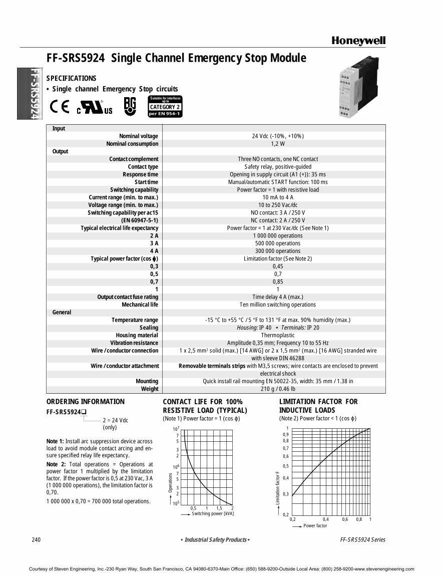
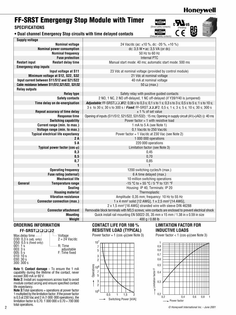
SPECIFICATIONS• Single channel Emergency Stop circuits
InputNominal voltage 24 Vdc (-10%, +10%)
Nominal consumption 1,2 WOutput
Contact complement Three NO contacts, one NC contactContact type Safety relay, positive-guided
Response time Opening in supply circuit (A1 (+)): 35 msStart time Manual/automatic START function: 100 ms
Switching capability Power factor = 1 with resistive loadCurrent range (min. to max.) 10 mA to 4 AVoltage range (min. to max.) 10 to 250 Vac/dcSwitching capability per ac15 NO contact: 3 A / 250 V
(EN 60947-5-1) NC contact: 2 A / 250 VTypical electrical life expectancy Power factor = 1 at 230 Vac/dc (See Note 1)
2 A 1 000 000 operations3 A 500 000 operations4 A 300 000 operations
Typical power factor (cos ϕϕϕϕϕ) Limitation factor (See Note 2)0,3 0,450,5 0,70,7 0,85
1 1Output contact fuse rating Time delay 4 A (max.)
Mechanical life Ten million switching operationsGeneral
Temperature range -15 °C to +55 °C / 5 °F to 131 °F at max. 90% humidity (max.)Sealing Housing: IP 40 • Terminals: IP 20
Housing material ThermoplasticVibration resistance Amplitude 0,35 mm; Frequency 10 to 55 Hz
Wire / conductor connection 1 x 2,5 mm2 solid (max.) [14 AWG] or 2 x 1,5 mm2 (max.) [16 AWG] stranded wirewith sleeve DIN 46288
Wire / conductor attachment Removable terminals strips with M3,5 screws; wire contacts are enclosed to preventelectrical shock
Mounting Quick install rail mounting EN 50022-35, width: 35 mm / 1.38 inWeight 210 g / 0.46 lb
ORDERING INFORMATIONFF-SRS5924
2 = 24 Vdc(only)
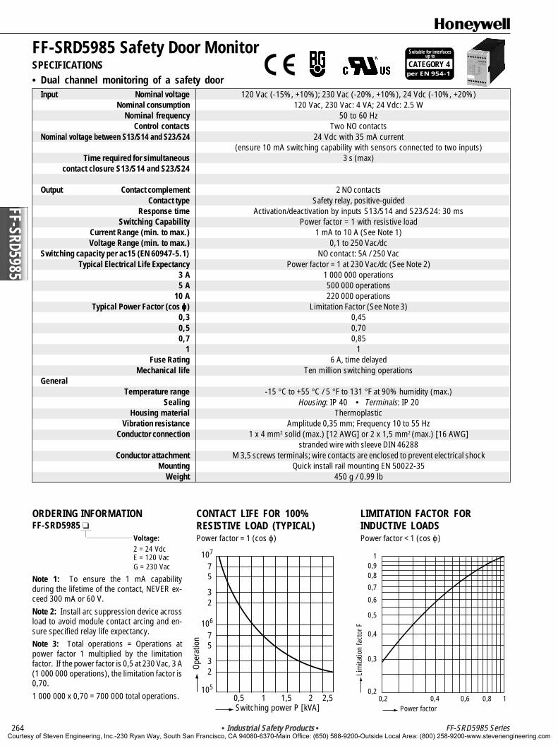
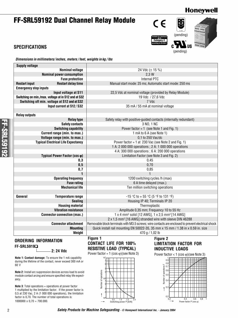
Note 1: Install arc suppression device acrossload to avoid module contact arcing and en-sure specified relay life expectancy.Note 2: Total operations = Operations atpower factor 1 multiplied by the limitationfactor. If the power factor is 0,5 at 230 Vac, 3 A(1 000 000 operations), the limitation factor is0,70.1 000 000 x 0,70 = 700 000 total operations.
CONTACT LIFE FOR 100%RESISTIVE LOAD (TYPICAL)(Note 1) Power factor = 1 (cos ϕ)
Courtesy of Steven Engineering, Inc.-230 Ryan Way, South San Francisco, CA 94080-6370-Main Office: (650) 588-9200-Outside Local Area: (800) 258-9200-www.stevenengineering.com
FF-S
RS59
24
• Industrial Safety Products • 241
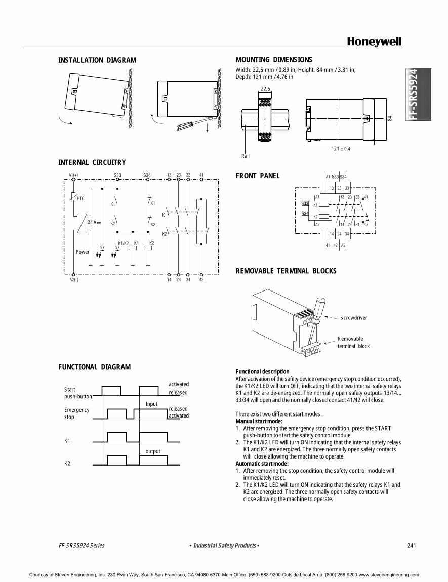
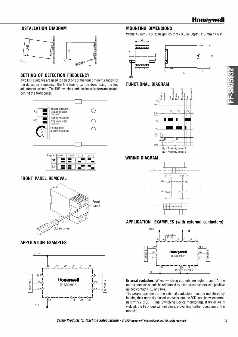
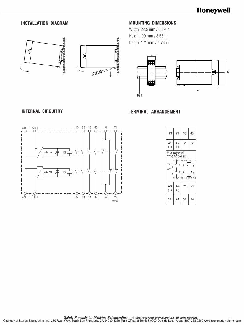
MOUNTING DIMENSIONSWidth: 22,5 mm / 0.89 in; Height: 84 mm / 3.31 in;Depth: 121 mm / 4.76 in
FRONT PANEL
REMOVABLE TERMINAL BLOCKS
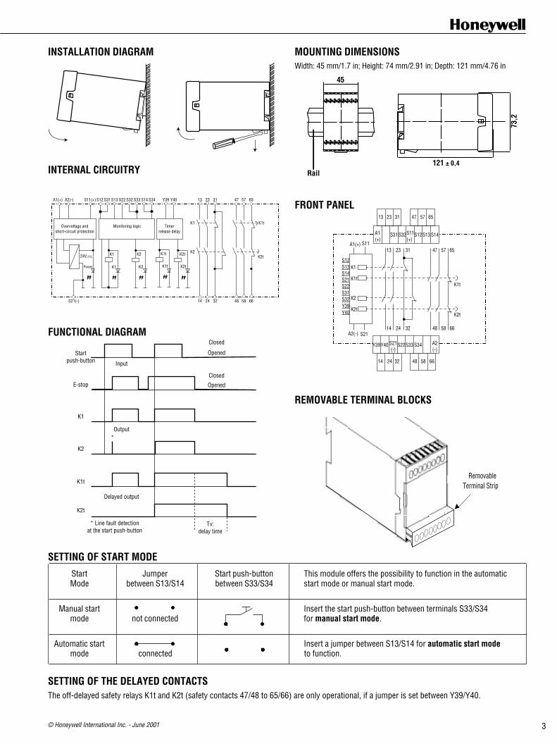
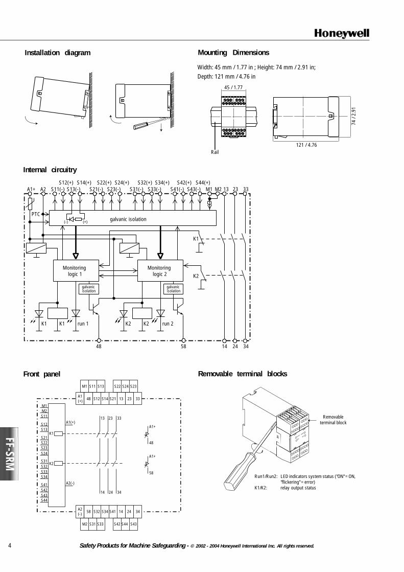
INSTALLATION DIAGRAM
INTERNAL CIRCUITRY
FUNCTIONAL DIAGRAM
Power
24 V
Rail121 ± 0,4
84
22,5
Start push-button
Emergencystop
K1
K2
activated
activated
released
releasedInput
output
Functional descriptionAfter activation of the safety device (emergency stop condition occurred),the K1/K2 LED will turn OFF, indicating that the two internal safety relaysK1 and K2 are de-energized. The normally open safety outputs 13/14...33/34 will open and the normally closed contact 41/42 will close.
There exist two different start modes:Manual start mode:1. After removing the emergency stop condition, press the START
push-button to start the safety control module.2. The K1/K2 LED will turn ON indicating that the internal safety relays
K1 and K2 are energized. The three normally open safety contactswill close allowing the machine to operate.
Automatic start mode:1. After removing the stop condition, the safety control module will
immediately reset.2. The K1/K2 LED will turn ON indicating that the safety relays K1 and
K2 are energized. The three normally open safety contacts willclose allowing the machine to operate.
Screwdriver
Removableterminal block
FF-SRS5924 Series
Courtesy of Steven Engineering, Inc.-230 Ryan Way, South San Francisco, CA 94080-6370-Main Office: (650) 588-9200-Outside Local Area: (800) 258-9200-www.stevenengineering.com
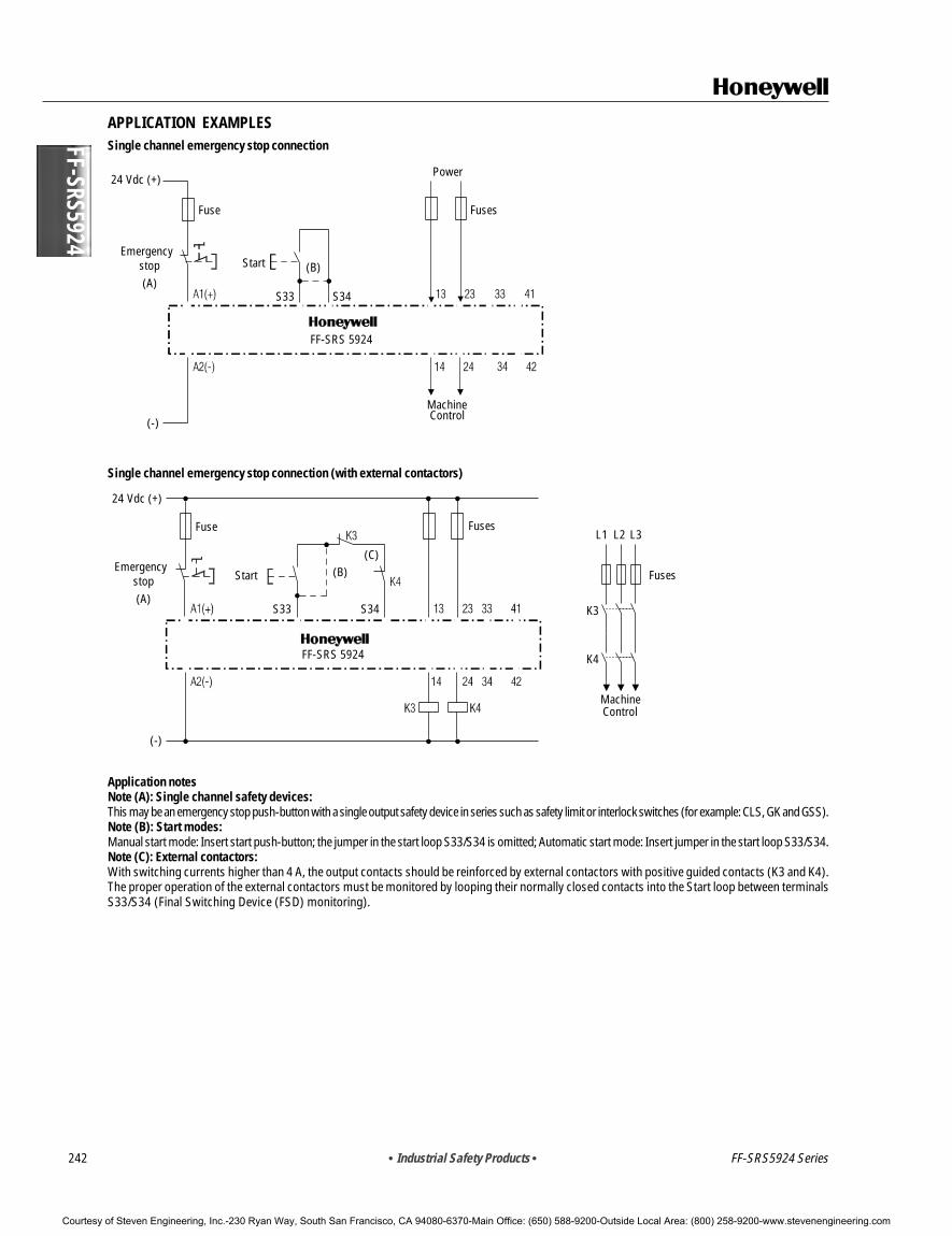
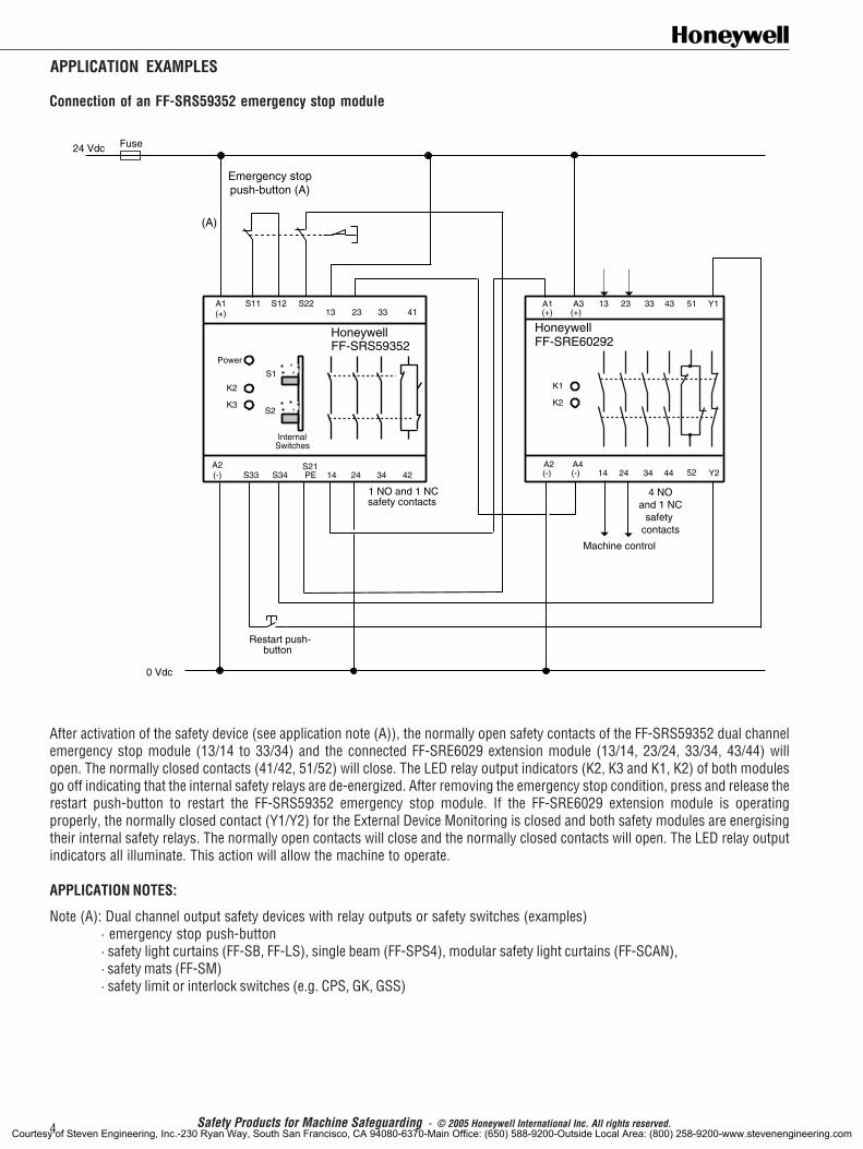
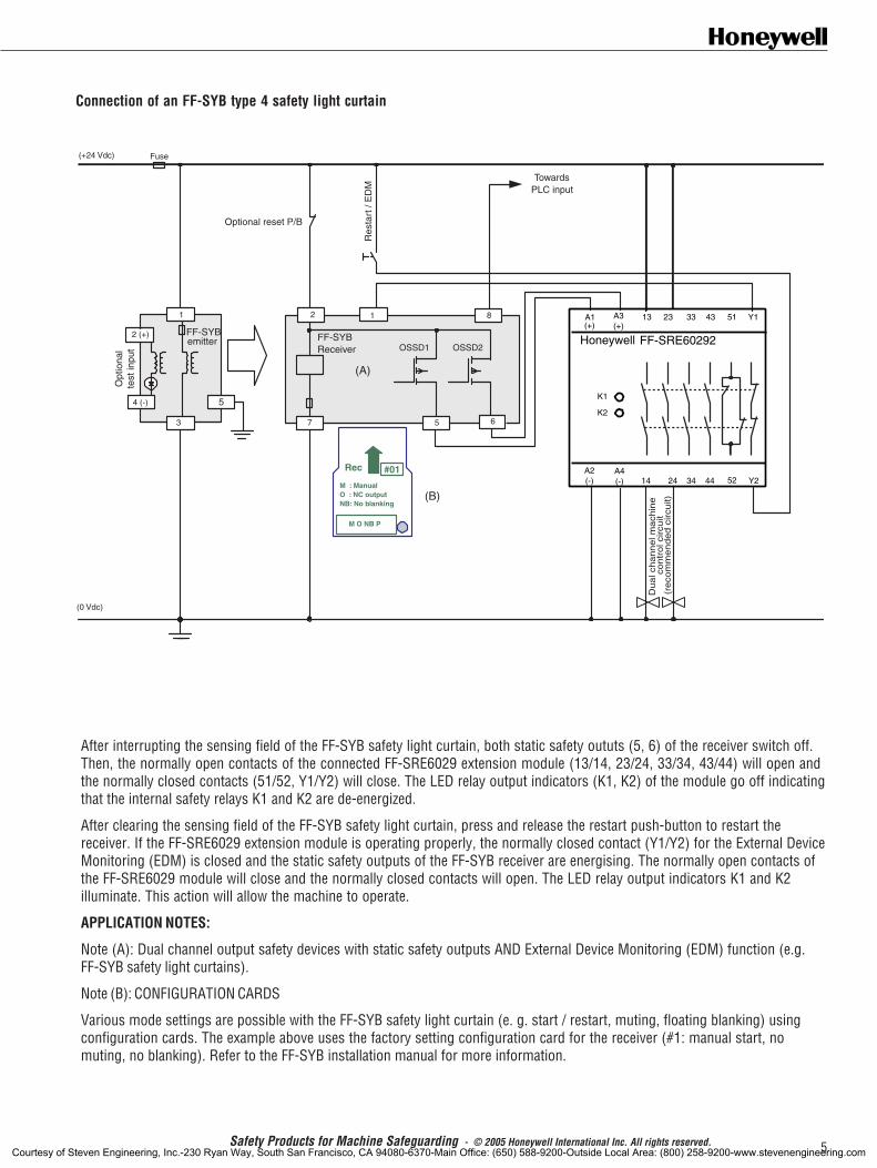
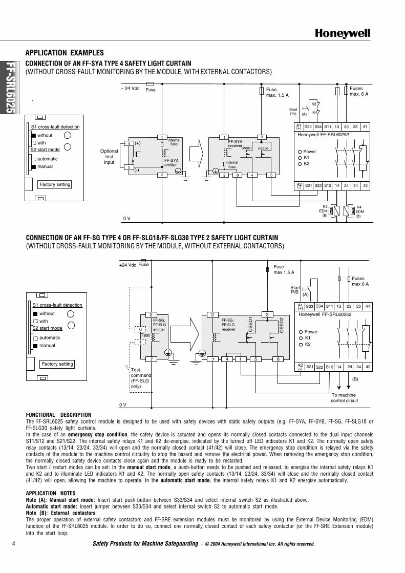
Single channel emergency stop connection (with external contactors)
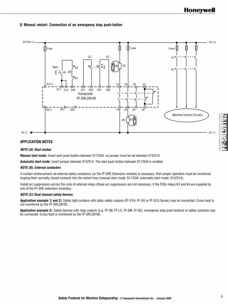
Application notesNote (A): Single channel safety devices:This may be an emergency stop push-button with a single output safety device in series such as safety limit or interlock switches (for example: CLS, GK and GSS).Note (B): Start modes:Manual start mode: Insert start push-button; the jumper in the start loop S33/S34 is omitted; Automatic start mode: Insert jumper in the start loop S33/S34.Note (C): External contactors:With switching currents higher than 4 A, the output contacts should be reinforced by external contactors with positive guided contacts (K3 and K4).The proper operation of the external contactors must be monitored by looping their normally closed contacts into the Start loop between terminalsS33/S34 (Final Switching Device (FSD) monitoring).
Start
FF-SRS 5924
Emergencystop
S33 S34(A)
(B)
24 Vdc (+)
(-)
Fuses
MachineControl
Fuse
Power
Start
FF-SRS 5924
Emergencystop
S33 S34(A)
MachineControl
K3
K4
Fuses
L2 L3L1
(B)(C)
24 Vdc (+)
(-)
Fuse Fuses
FF-SRS5924 Series
Courtesy of Steven Engineering, Inc.-230 Ryan Way, South San Francisco, CA 94080-6370-Main Office: (650) 588-9200-Outside Local Area: (800) 258-9200-www.stevenengineering.com
• Industrial Safety Products • 243
FF-S
RS59
34
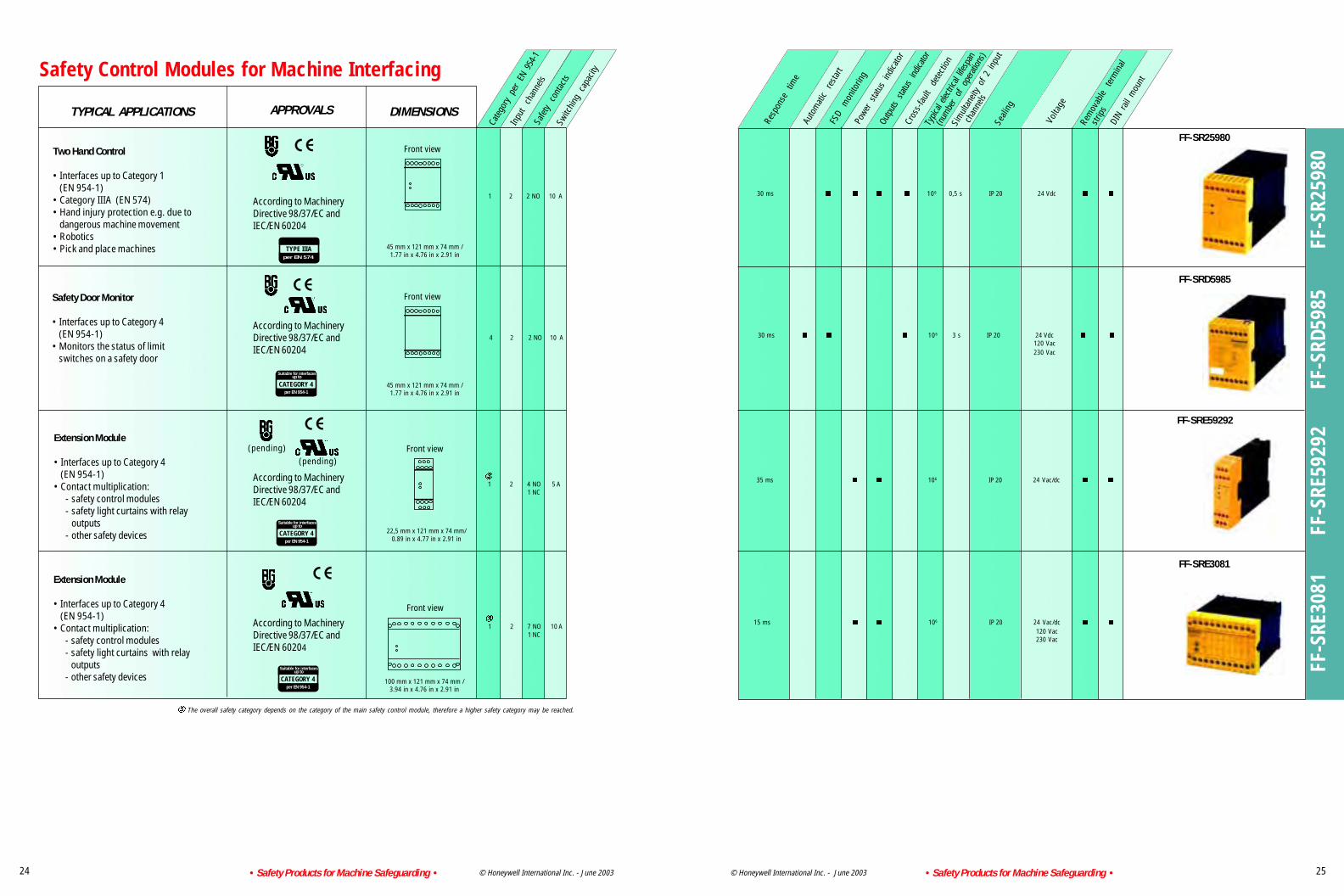
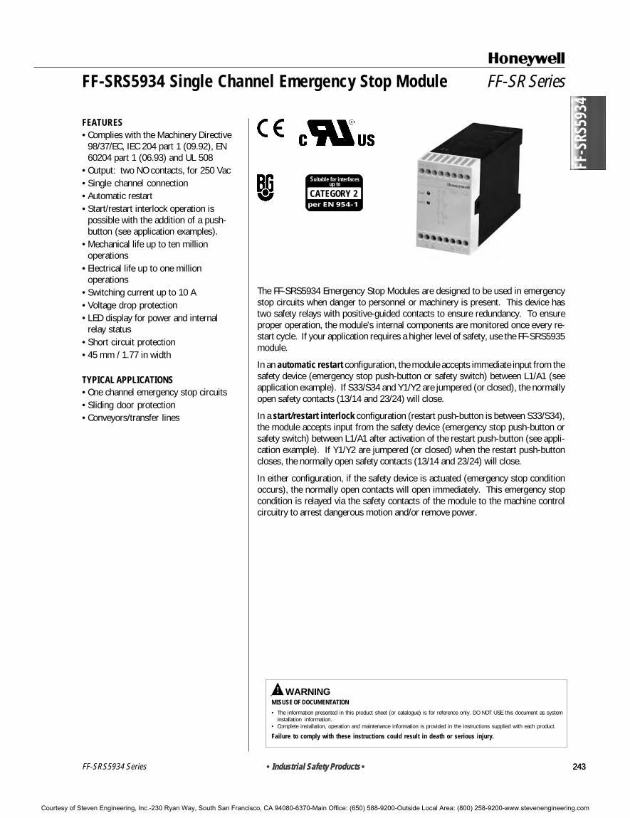
The FF-SRS5934 Emergency Stop Modules are designed to be used in emergencystop circuits when danger to personnel or machinery is present. This device hastwo safety relays with positive-guided contacts to ensure redundancy. To ensureproper operation, the module’s internal components are monitored once every re-start cycle. If your application requires a higher level of safety, use the FF-SRS5935module.
In an automatic restart configuration, the module accepts immediate input from thesafety device (emergency stop push-button or safety switch) between L1/A1 (seeapplication example). If S33/S34 and Y1/Y2 are jumpered (or closed), the normallyopen safety contacts (13/14 and 23/24) will close.
In a start/restart interlock configuration (restart push-button is between S33/S34),the module accepts input from the safety device (emergency stop push-button orsafety switch) between L1/A1 after activation of the restart push-button (see appli-cation example). If Y1/Y2 are jumpered (or closed) when the restart push-buttoncloses, the normally open safety contacts (13/14 and 23/24) will close.
In either configuration, if the safety device is actuated (emergency stop conditionoccurs), the normally open contacts will open immediately. This emergency stopcondition is relayed via the safety contacts of the module to the machine controlcircuitry to arrest dangerous motion and/or remove power.
CATEGORY 2per EN 954-1
Suitable for interfacesup to
FF-SR Series
FEATURES• Complies with the Machinery Directive
98/37/EC, IEC 204 part 1 (09.92), EN60204 part 1 (06.93) and UL 508
• Output: two NO contacts, for 250 Vac• Single channel connection• Automatic restart• Start/restart interlock operation is
possible with the addition of a push-button (see application examples).
• Mechanical life up to ten millionoperations
• Electrical life up to one millionoperations
• Switching current up to 10 A• Voltage drop protection• LED display for power and internal
relay status• Short circuit protection• 45 mm / 1.77 in width
TYPICAL APPLICATIONS• One channel emergency stop circuits• Sliding door protection• Conveyors/transfer lines
FF-SRS5934 Single Channel Emergency Stop Module
• Industrial Safety Products • 243
! WARNINGMISUSE OF DOCUMENTATION• The information presented in this product sheet (or catalogue) is for reference only. DO NOT USE this document as system
installation information.• Complete installation, operation and maintenance information is provided in the instructions supplied with each product.
Failure to comply with these instructions could result in death or serious injury.
FF-SRS5934 Series
Courtesy of Steven Engineering, Inc.-230 Ryan Way, South San Francisco, CA 94080-6370-Main Office: (650) 588-9200-Outside Local Area: (800) 258-9200-www.stevenengineering.com
244 • Industrial Safety Products •
FF-SRS5934
FF-SRS5934 Series
CATEGORY 2per EN 954-1
Suitable for interfacesup to
FF-SRS5934 Single Channel Emergency Stop Module
SPECIFICATIONS• Single channel Emergency Stop circuits
Output Contact complement 2 NO contactsContact type Safety relay, positive-guided
Response time 35 msSwitching Capability Power factor = 1 with resistive load
Current Range (min. to max.) 10 mA to 6 AVoltage Range (min. to max.) 0,1 to 250 Vac/dc
Switching capability per ac15 (EN 60947-5.1) NO contact: 5 A / 250 Vac - NC contact: 2 A / 250 Vac Typical Electrical Life Expectancy Power factor = 1 at 230 Vac/dc (See Note 1)
3 A 1 000 000 operations5 A 500 000 operations
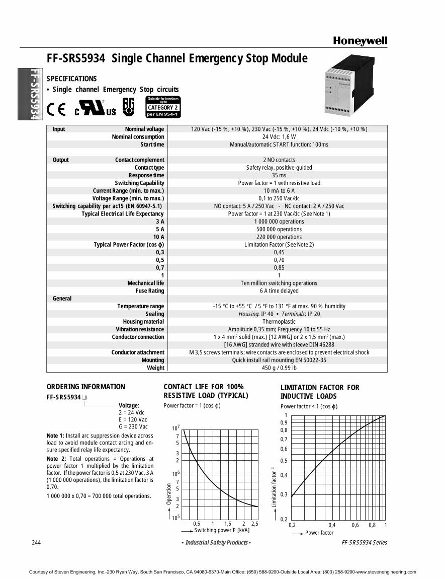
10 A 220 000 operationsTypical Power Factor (cos ϕ ϕ ϕ ϕ ϕ) Limitation Factor (See Note 2)
0,3 0,450,5 0,700,7 0,85
1 1Mechanical life Ten million switching operations
Fuse Rating 6 A time delayedGeneral
Temperature range -15 °C to +55 °C / 5 °F to 131 °F at max. 90 % humiditySealing Housing: IP 40 • Terminals: IP 20
Housing material ThermoplasticVibration resistance Amplitude 0,35 mm; Frequency 10 to 55 Hz
Conductor connection 1 x 4 mm2 solid (max.) [12 AWG] or 2 x 1,5 mm2 (max.)[16 AWG] stranded wire with sleeve DIN 46288
Conductor attachment M 3,5 screws terminals; wire contacts are enclosed to prevent electrical shockMounting Quick install rail mounting EN 50022-35
Weight 450 g / 0.99 lb
ORDERING INFORMATIONFF-SRS5934
Voltage:2 = 24 VdcE = 120 VacG = 230 Vac
Note 1: Install arc suppression device acrossload to avoid module contact arcing and en-sure specified relay life expectancy.Note 2: Total operations = Operations atpower factor 1 multiplied by the limitationfactor. If the power factor is 0,5 at 230 Vac, 3 A(1 000 000 operations), the limitation factor is0,70.1 000 000 x 0,70 = 700 000 total operations.
CONTACT LIFE FOR 100%RESISTIVE LOAD (TYPICAL)Power factor = 1 (cos ϕ)
Courtesy of Steven Engineering, Inc.-230 Ryan Way, South San Francisco, CA 94080-6370-Main Office: (650) 588-9200-Outside Local Area: (800) 258-9200-www.stevenengineering.com
• Industrial Safety Products • 245
FF-S
RS59
34
FF-SRS5934 Series
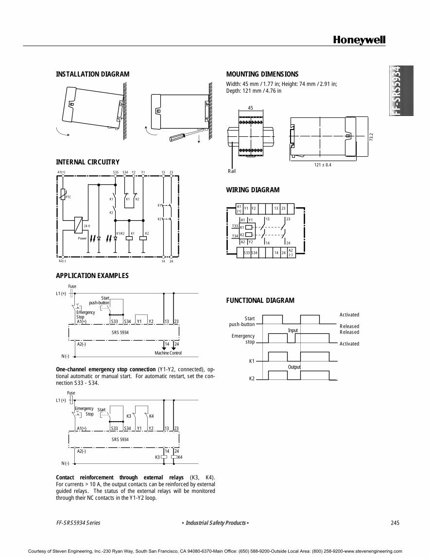
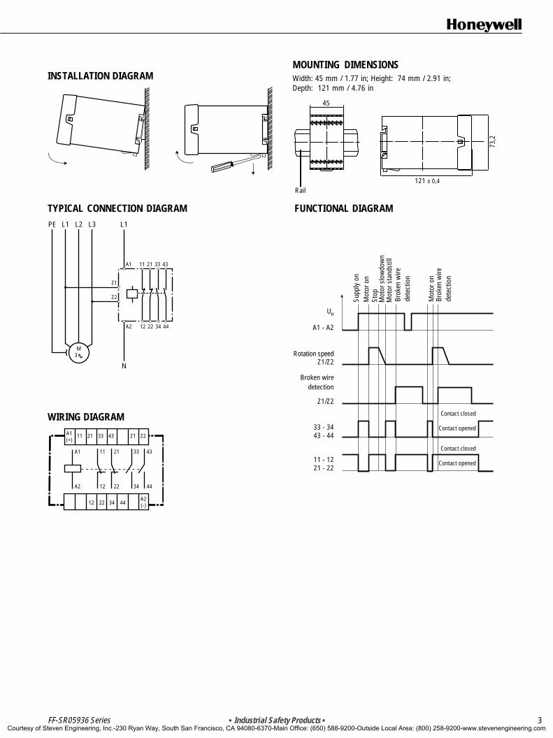
MOUNTING DIMENSIONSWidth: 45 mm / 1.77 in; Height: 74 mm / 2.91 in;Depth: 121 mm / 4.76 in
Rail121 ± 0,4
73,2
45
WIRING DIAGRAM
13 23
14 24
A1(+)
A2(-)
Y2Y1
S33 S34 14 24
23
Y1A1
Y2A2
K1
K2
T33
T34
13
FUNCTIONAL DIAGRAM
Start push-button
K1
K2
Emergency stop(stop)
Output
Input Releasedactivited
121 ± 0.4
73.2
INSTALLATION DIAGRAM
INTERNAL CIRCUITRY
K1
K1
K2
K1 K2
K2
K1/K2 K1 K2Power
14 24
24 V
A1(+)
A2(-)
PTC
Y1S33 S34 Y2 13 23
APPLICATION EXAMPLES
L1 (+)
N (-)
A1(+)
Startpush-button
S33 S34 Y2 13 23
14 24
Y1
A2(-)
SRS 5934
EmergencyStop
Machine Control
Fuse
One-channel emergency stop connection (Y1-Y2, connected), op-tional automatic or manual start. For automatic restart, set the con-nection S33 - S34.
L1 (+)
N (-)
A1(+)
Start
S33 S34 Y2 13 23
14K3 K4
K3 K4
24
Y1
A2(-)
SRS 5934
EmergencyStop
Fuse
Contact reinforcement through external relays (K3, K4).For currents > 10 A, the output contacts can be reinforced by externalguided relays. The status of the external relays will be monitoredthrough their NC contacts in the Y1-Y2 loop.
Startpush-button
Emergencystop
K1
K2
Activated
ReleasedReleased
Activated
Courtesy of Steven Engineering, Inc.-230 Ryan Way, South San Francisco, CA 94080-6370-Main Office: (650) 588-9200-Outside Local Area: (800) 258-9200-www.stevenengineering.com
! WARNINGMISUSE OF DOCUMENTATION• The information presented in this product sheet (or catalogue) is for reference only. DO NOT USE this document as system
installation information.• Complete installation, operation and maintenance information is provided in the instructions supplied with each product.
Failure to comply with these instructions could result in death or serious injury.
FF-S
RS59
25
• Industrial Safety Products • 247
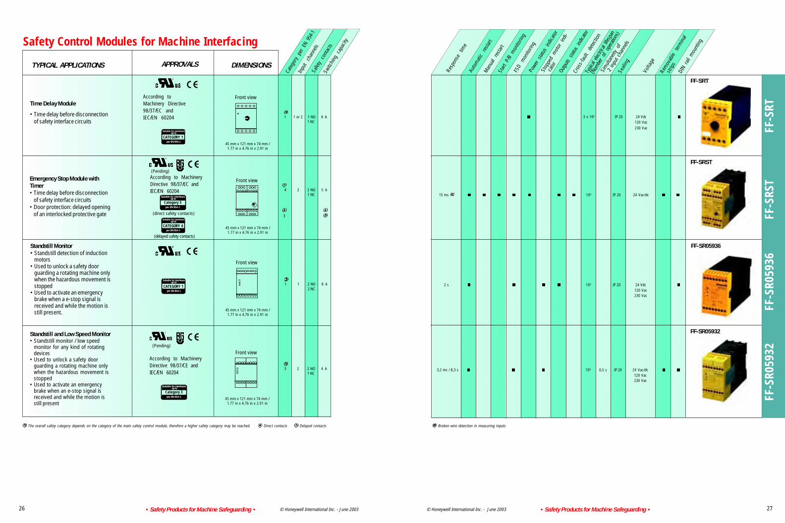
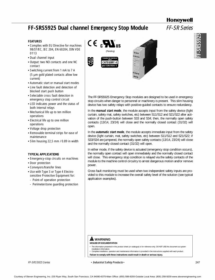
The FF-SRS5925 Emergency Stop modules are designed to be used in emergencystop circuits when danger to personnel or machinery is present. This slim housingdevice has two safety relays with positive-guided contacts to ensure redundancy.
In the manual start mode, the module accepts input from the safety device (lightcurtain, safety mat, safety switches, etc) between S11/S12 and S21/S22 after acti-vation of the push-button between S33 and S34; then, the normally open safetycontacts (13/14, 23/24) will close and the normally closed contact (31/32) willopen.
In the automatic start mode, the module accepts immediate input from the safetydevice (light curtain, mat, safety switches, etc) between S11/S12 and S21/S22; ifS33/S34 are jumpered, the normally open safety contacts (13/14, 23/24) will closeand the normally closed contact (31/32) will open.
In either mode, if the safety device is actuated (emergency stop condition occurs),the normally open contact will open immediately and the normally closed contactwill close. This emergency stop condition is relayed via the safety contacts of themodule to the machine control circuitry to arrest dangerous motion and/or removepower.
Cross fault monitoring must be used when two independent safety inputs are pro-vided to this module to increase the overall safety level of the solution (see typicalapplication examples).
Courtesy of Steven Engineering, Inc.-230 Ryan Way, South San Francisco, CA 94080-6370-Main Office: (650) 588-9200-Outside Local Area: (800) 258-9200-www.stevenengineering.com
Nominal power consumption Dc: 2 W (approximately)Nominal frequency 50 to 60 Hz
Start time Manual START function: 40 msAutomatic START function: 500 ms
Nominal voltage at S11 23 Vdc (provided by control module)Input current between S11/S12 and S21/S22 40 mA
Minimum voltage at S12 21 Vdc when activatedCable resistance between S11/S12 and S21/S22 68 Ω (max.)
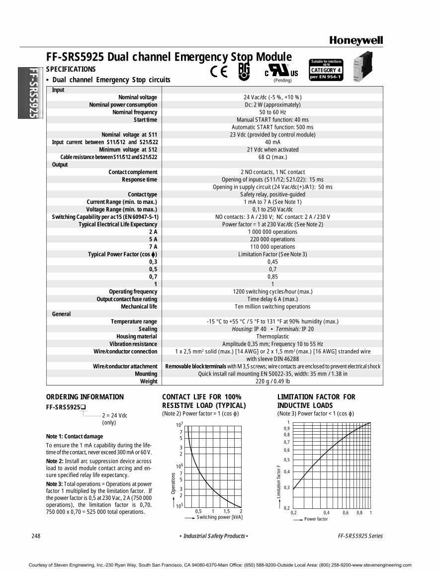
OutputContact complement 2 NO contacts, 1 NC contact
Response time Opening of inputs (S11/12; S21/22): 15 msOpening in supply circuit (24 Vac/dc(+)/A1): 50 ms
Contact type Safety relay, positive-guidedCurrent Range (min. to max.) 1 mA to 7 A (See Note 1)Voltage Range (min. to max.) 0,1 to 250 Vac/dc
Switching Capability per ac15 (EN 60947-5-1) NO contacts: 3 A / 230 V; NC contact: 2 A / 230 VTypical Electrical Life Expectancy Power factor = 1 at 230 Vac/dc (See Note 2)
2 A 1 000 000 operations5 A 220 000 operations7 A 110 000 operations
Typical Power Factor (cos ϕϕϕϕϕ) Limitation Factor (See Note 3)0,3 0,450,5 0,70,7 0,85
1 1Operating frequency 1200 switching cycles/hour (max.)
Output contact fuse rating Time delay 6 A (max.)Mechanical life Ten million switching operations
GeneralTemperature range -15 °C to +55 °C / 5 °F to 131 °F at 90% humidity (max.)
Sealing Housing: IP 40 • Terminals: IP 20Housing material Thermoplastic
Vibration resistance Amplitude 0,35 mm; Frequency 10 to 55 HzWire/conductor connection 1 x 2,5 mm2 solid (max.) [14 AWG] or 2 x 1,5 mm2 (max.) [16 AWG] stranded wire
with sleeve DIN 46288Wire/conductor attachment Removable block terminals with M 3,5 screws; wire contacts are enclosed to prevent electrical shock
Mounting Quick install rail mounting EN 50022-35, width: 35 mm / 1.38 inWeight 220 g / 0.49 lb
ORDERING INFORMATIONFF-SRS5925
2 = 24 Vdc(only)
Note 1: Contact damageTo ensure the 1 mA capability during the life-time of the contact, never exceed 300 mA or 60 V.Note 2: Install arc suppression device acrossload to avoid module contact arcing and en-sure specified relay life expectancy.Note 3: Total operations = Operations at powerfactor 1 multiplied by the limitation factor. Ifthe power factor is 0,5 at 230 Vac, 2 A (750 000operations), the limitation factor is 0,70.750 000 x 0,70 = 525 000 total operations.
CONTACT LIFE FOR 100%RESISTIVE LOAD (TYPICAL)(Note 2) Power factor = 1 (cos ϕ)
107
75
32
106
105
75
32
0,5 1 1,5 2Switching power [kVA]
Oper
atio
ns
Power factor0,2
0,2
0,3
0,4
0,5
0,6
0,7
0,80,9
1
0,4 0,6 0,8 1
Lim
itatio
n fa
ctor
F
Courtesy of Steven Engineering, Inc.-230 Ryan Way, South San Francisco, CA 94080-6370-Main Office: (650) 588-9200-Outside Local Area: (800) 258-9200-www.stevenengineering.com
FF-S
RS59
25
• Industrial Safety Products • 249
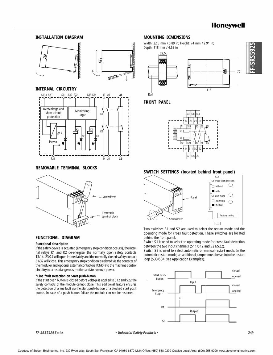
MOUNTING DIMENSIONSWidth: 22,5 mm / 0.89 in; Height: 74 mm / 2.91 in;Depth: 118 mm / 4.65 in
FRONT PANEL
SWITCH SETTINGS (located behind front panel)
FF-SRS5925 Series
INSTALLATION DIAGRAM
INTERNAL CIRCUITRY
REMOVABLE TERMINAL BLOCKS
FUNCTIONAL DIAGRAMFunctional descriptionIf the safety device is actuated (emergency stop condition occurs), the inter-nal relays K1 and K2 de-energize, the normally open safety contacts13/14..23/24 will open immediately and the normally closed safety contact31/32 will close. This emergency stop condition is relayed via the contacts ofthe module (and optional external contactors K3/K4) to the machine controlcircuitry to arrest dangerous motion and/or remove power.
*Line fault Detection on Start push-buttonIf the start push button is closed before voltage is applied to S12 and S22 thesafety contacts of the module cannot close. This additional feature ensuresthe detection of a line fault via the start push-button or a blocked start pushbutton. In case of a push-button failure the module can not be restarted.
31
32
Overvoltage andshort-circuitprotection
MonitoringLogic
Power
24 V
Panel
Screwdriver
S1 cross fault detection
S2 start mode
without
with
automatic
manual
Factory setting
Start push-button
closed
opened
Input
Output
EmergencyStop
closed
opened
K1
K2
Two switches S1 and S2 are used to select the restart mode and theoperating mode for cross fault detection. These switches are locatedbehind the front panel.Switch S1 is used to select an operating mode for cross fault detectionbetween the two input channels (S11/S12 and S21/S22).Switch S2 is used to select automatic or manual restart mode. In theautomatic restart mode, an additional jumper must be set into the restartloop (S33/S34, see Application Examples).
Screwdriver
Removableterminal block
Rail118
74
22,5
Courtesy of Steven Engineering, Inc.-230 Ryan Way, South San Francisco, CA 94080-6370-Main Office: (650) 588-9200-Outside Local Area: (800) 258-9200-www.stevenengineering.com
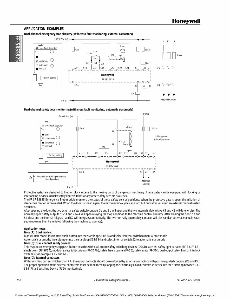
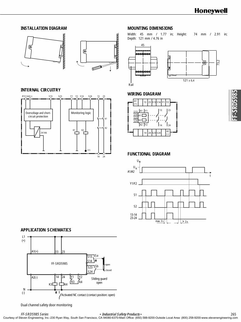
Protective gates are designed to limit or block access to the moving parts of dangerous machinery. These gates can be equipped with locking orinterlocking devices, usually safety limit switches or any other safety sensors/switches.The FF-SRS5925 Emergency Stop module monitors the status of these safety sensor positions. When the protective gate is open, the initiation ofdangerous motion is prevented. When the door is closed again, the next machine cycle can start, but only after initiating an external manual restartsequence.After opening the door, the two external safety switch contacts Sa and Sb will open and the two internal safety relays K1 and K2 will de-energize. Thenormally open safety outputs 13/14 and 23/24 will open relaying the stop condition to the machine control circuitry. After closing the door, Sa andSb close and the internal relays K1 and K2 will energize automatically. The two normally open safety contacts will close and an external manual restartsequence may then be initiated (allowing the machine to operate).
Application notes:Note (A): Start modes:Manual start mode: Insert start push-button into the start loop S33/S34 and select internal switch to manual start modeAutomatic start mode: Insert jumper into the start loop S33/S34 and select internal switch S2 to automatic start modeNote (B): Dual channel safety devices:This may be an emergency stop push-button in series with dual output safety switching devices (OSSD) such as: safety light curtains (FF-SB, FF-LS),single beam (FF-SPS4), modular safety light curtains (FF-SCAN), safety laser scanner (FF-SE), safety mats (FF-SM), dual output safety limit or interlockswitches (for example, CLS and GK).Note (C): External contactors:With switching currents higher than 7 A, the output contacts should be reinforced by external contactors with positive guided contacts (K3 and K4).The proper operation of the external contactors must be monitored by looping their normally closed contacts in series into the Start loop between S33/S34 (Final Switching Device (FSD) monitoring).
Courtesy of Steven Engineering, Inc.-230 Ryan Way, South San Francisco, CA 94080-6370-Main Office: (650) 588-9200-Outside Local Area: (800) 258-9200-www.stevenengineering.com
• Industrial Safety Products • 251
! WARNINGMISUSE OF DOCUMENTATION• The information presented in this product sheet (or catalogue) is for reference only. DO NOT USE this document as system
installation information.• Complete installation, operation and maintenance information is provided in the instructions supplied with each product.
Failure to comply with these instructions could result in death or serious injury.
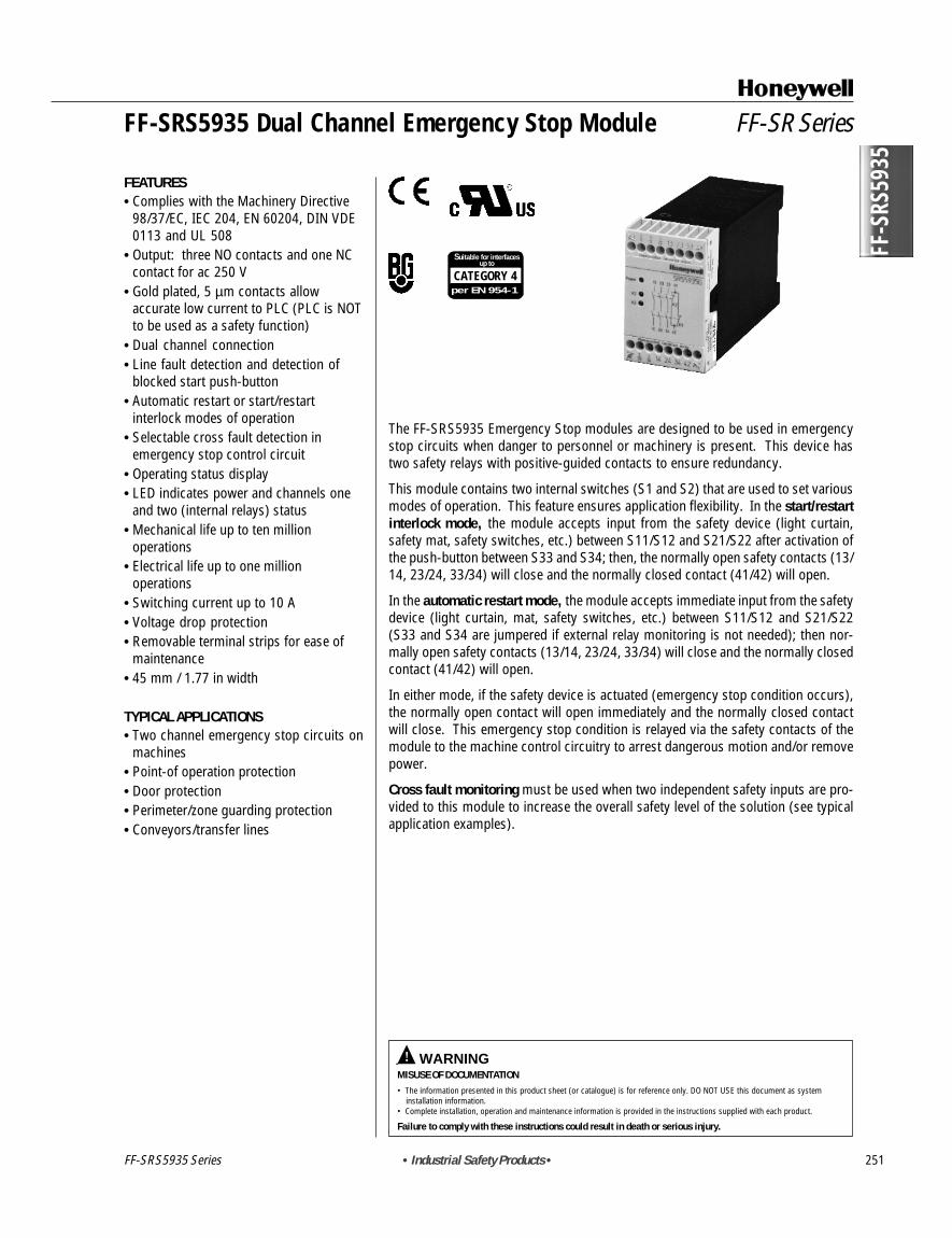
The FF-SRS5935 Emergency Stop modules are designed to be used in emergencystop circuits when danger to personnel or machinery is present. This device hastwo safety relays with positive-guided contacts to ensure redundancy.
This module contains two internal switches (S1 and S2) that are used to set variousmodes of operation. This feature ensures application flexibility. In the start/restartinterlock mode, the module accepts input from the safety device (light curtain,safety mat, safety switches, etc.) between S11/S12 and S21/S22 after activation ofthe push-button between S33 and S34; then, the normally open safety contacts (13/14, 23/24, 33/34) will close and the normally closed contact (41/42) will open.
In the automatic restart mode, the module accepts immediate input from the safetydevice (light curtain, mat, safety switches, etc.) between S11/S12 and S21/S22(S33 and S34 are jumpered if external relay monitoring is not needed); then nor-mally open safety contacts (13/14, 23/24, 33/34) will close and the normally closedcontact (41/42) will open.
In either mode, if the safety device is actuated (emergency stop condition occurs),the normally open contact will open immediately and the normally closed contactwill close. This emergency stop condition is relayed via the safety contacts of themodule to the machine control circuitry to arrest dangerous motion and/or removepower.
Cross fault monitoring must be used when two independent safety inputs are pro-vided to this module to increase the overall safety level of the solution (see typicalapplication examples).
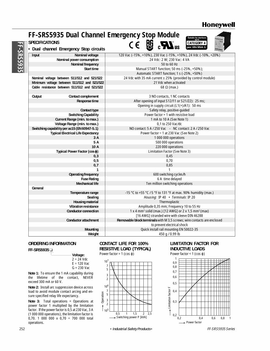
Input Nominal voltage 120 Vac (-15%, +10%), 230 Vac (-15%, +10%), 24 Vdc (-10%, +20%)Nominal power consumption 24 Vdc: 2 W; 230 Vac: 4 VA
Nominal frequency 50 to 60 HzStart time Manual START function; 50 ms (-25%, +50%);
Automatic START function; 1 s (-25%, +50%)Nominal voltage between S11/S12 and S21/S22 24 Vdc with 35 mA current ± 25% (provided by control module)Minimum voltage between S11/S12 and S21/S22 21 Vdc when activatedCable resistance between S11/S12 and S21/S22 68 Ω (max.)
Output Contact complement 3 NO contacts, 1 NC contactsResponse time After opening of input S12/11 or S21/22): 25 ms;
Opening in supply circuit (L1(+)/A1): 50 msContact type Safety relay, positive-guided
Switching Capability Power factor = 1 with resistive loadCurrent Range (min. to max.) 1 mA to 10 A (See Note 1)Voltage Range (min. to max.) 0,1 to 250 Vac/dc
Switching capability per ac15 (EN 60947-5.1) NO contact: 5 A / 250 Vac - NC contact: 2 A / 250 VacTypical Electrical Life Expectancy Power factor = 1 at 230 Vac (See Note 2)
3 A 1 000 000 operations5 A 500 000 operations
10 A 220 000 operationsTypical Power Factor (cos ϕϕϕϕϕ) Limitation Factor (See Note 3)
0,3 0,450,5 0,700,7 0,85
1 1Operating frequency 600 switching cycles/h
Fuse Rating 6 A time delayedMechanical life Ten million switching operations
GeneralTemperature range -15 ° C to +55 ° C / 5 ° F to 131 ° F at max. 90% humidity (max.)
Sealing Housing: IP 40 • Terminals: IP 20Housing material Thermoplastic
Vibration resistance Amplitude 0,35 mm; Frequency 10 to 55 HzConductor connection 1 x 4 mm2 solid (max.) [12 AWG] or 2 x 1,5 mm2 (max)
[16 AWG] stranded wire with sleeve DIN 46288Conductor attachment Removable block terminals with M 3,5 screws; wire contacts are enclosed
to prevent electrical shockMounting Quick install rail mounting EN 50022-35
Weight 450 g / 0.99 lb
ORDERING INFORMATIONFF-SRS5935
Voltage:2 = 24 VdcE = 120 VacG = 230 Vac
Note 1: To ensure the 1 mA capability duringthe lifetime of the contact, NEVERexceed 300 mA or 60 V.Note 2: Install arc suppression device acrossload to avoid module contact arcing and en-sure specified relay life expectancy.Note 3: Total operations = Operations atpower factor 1 multiplied by the limitationfactor. If the power factor is 0,5 at 230 Vac, 3 A(1 000 000 operations), the limitation factor is0,70. 1 000 000 x 0,70 = 700 000 totaloperations.
CONTACT LIFE FOR 100%RESISTIVE LOAD (TYPICAL)Power factor = 1 (cos ϕ)
FF-SRS5935
Power factor0,2
0,2
0,3
0,4
0,5
0,6
0,7
0,80,9
1
0,4 0,6 0,8 1
Lim
itatio
n fa
ctor
F
107
75
32
106
105
75
32
0,5 1 1,5 2 2,5Switching power P [kVA]
Oper
atio
n
• Industrial Safety Products • 253
Startpush-button
K2
Min 0.5 s
K3
Emergency-stop
* Line fault detection at the Start push-button
*
2S1
S2
Emergency-stop nocross-fault detection
Emergency-stopcross-fault detection
Autostart
Handstart
Factory Setting
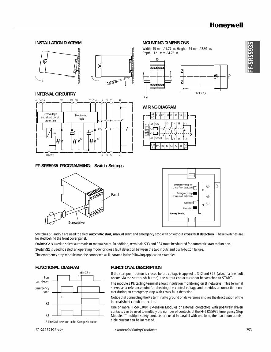
MOUNTING DIMENSIONSWidth: 45 mm / 1.77 in; Height: 74 mm / 2.91 in;Depth: 121 mm / 4.76 in
Rail121 ± 0,4
73,2
45
WIRING DIAGRAM
13 23
14 24
33
34
41
42
A1(+)
A2(-)
S21/PE
S12 S22S11
S33 S34 14 24 34 42
33
S22A1
S21/PEA2
K2
K3
4113
S11S12S33S34
23
FUNCTIONAL DESCRIPTIONIf the start push-button is closed before voltage is applied to S12 and S22 (also, if a line faultoccurs via the start push-button), the output contacts cannot be switched to START.The module’s PE testing terminal allows insulation monitoring on IT networks. This terminalserves as a reference point for checking the control voltage and provides a connection con-tact during an emergency stop with cross fault detection.Notice that connecting the PE terminal to ground on dc versions implies the deactivation of theinternal short-circuit protection.One or more FF-SRE3081 Extension Modules or external contactors with positively drivencontacts can be used to multiply the number of contacts of the FF-SRS5935 Emergency StopModule. If multiple safety contacts are used in parallel with one load, the maximum admis-sible current can be increased.
FF-SRS5935 Series
Emergencystop
Emergency stop nocross-fault detection
Emergency stopcross-fault detection
Autostart
Handstart
Factory Setting
INSTALLATION DIAGRAM
INTERNAL CIRCUITRY
Overvoltageand short-circuit
protection
Monitoring logic
K2
K3K2 K3
K2 K3
14S21/PE(-) 24
24 V
A1(+)A2(-) S11 S12 S22 S33 S34 4113 23
34 42
33
FF-SRS5935 PROGRAMMING: Switch Settings
Switches S1 and S2 are used to select automatic start, manual start and emergency stop with or without cross fault detection. These switches arelocated behind the front cover panel.Switch S2 is used to select automatic or manual start. In addition, terminals S33 and S34 must be shunted for automatic start to function.Switch S1 is used to select an operating mode for cross fault detection between the two inputs and push-button failure.The emergency stop module must be connected as illustrated in the following application examples.
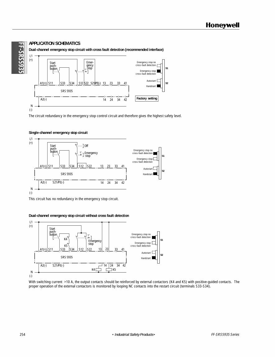
The circuit redundancy in the emergency stop control circuit and therefore gives the highest safety level.
Single-channel emergency stop circuit
L1(+)
N(-)
A1(+) S11
Startpush-button
Off
Emergency stop
S33 S34 S22 13 23 33 41
14 24 34 42
S12
A2(-) S21/PE(-)
SRS 5935
S1
S2
Emergency-stop nocross-fault detection
Emergency-stopcross-fault detection
Autostart
Handstart
This circuit has no redundancy in the emergency stop circuit.
Dual-channel emergency stop circuit without cross fault detection
L1(+)
N(-)
A1(+) S11
Startpush-button
Emergencystop
S33 S34 S22 13
K4
K4 K5
K523 33 41
14 24 34 42
S12
A2(-) S21/PE(-)
SRS 5935
S1
S2
Emergency-stop nocross-fault detection
Emergency-stopcross-fault detection
Autostart
Handstart
With switching current >10 A, the output contacts should be reinforced by external contactors (K4 and K5) with positive-guided contacts. Theproper operation of the external contactors is monitored by looping NC contacts into the restart circuit (terminals S33-S34).
FF-SRS5935 Series
Emergency stop nocross-fault detection
Emergency stopcross-fault detection
Autostart
Handstart
Emergency stop nocross-fault detection
Emergency stopcross-fault detection
Autostart
Handstart
Emergency stop nocross-fault detection
Emergency stopcross-fault detection
Autostart
Handstart
Factory setting
FF-SRS5935
! WARNINGMISUSE OF DOCUMENTATION• The information presented in this product sheet (or catalogue) is for reference only. DO NOT USE this document as system
installation information.• Complete installation, operation and maintenance information is provided in the instructions supplied with each product.
Failure to comply with these instructions could result in death or serious injury.
FF-S
RS59
88
• Industrial Safety Products • 255
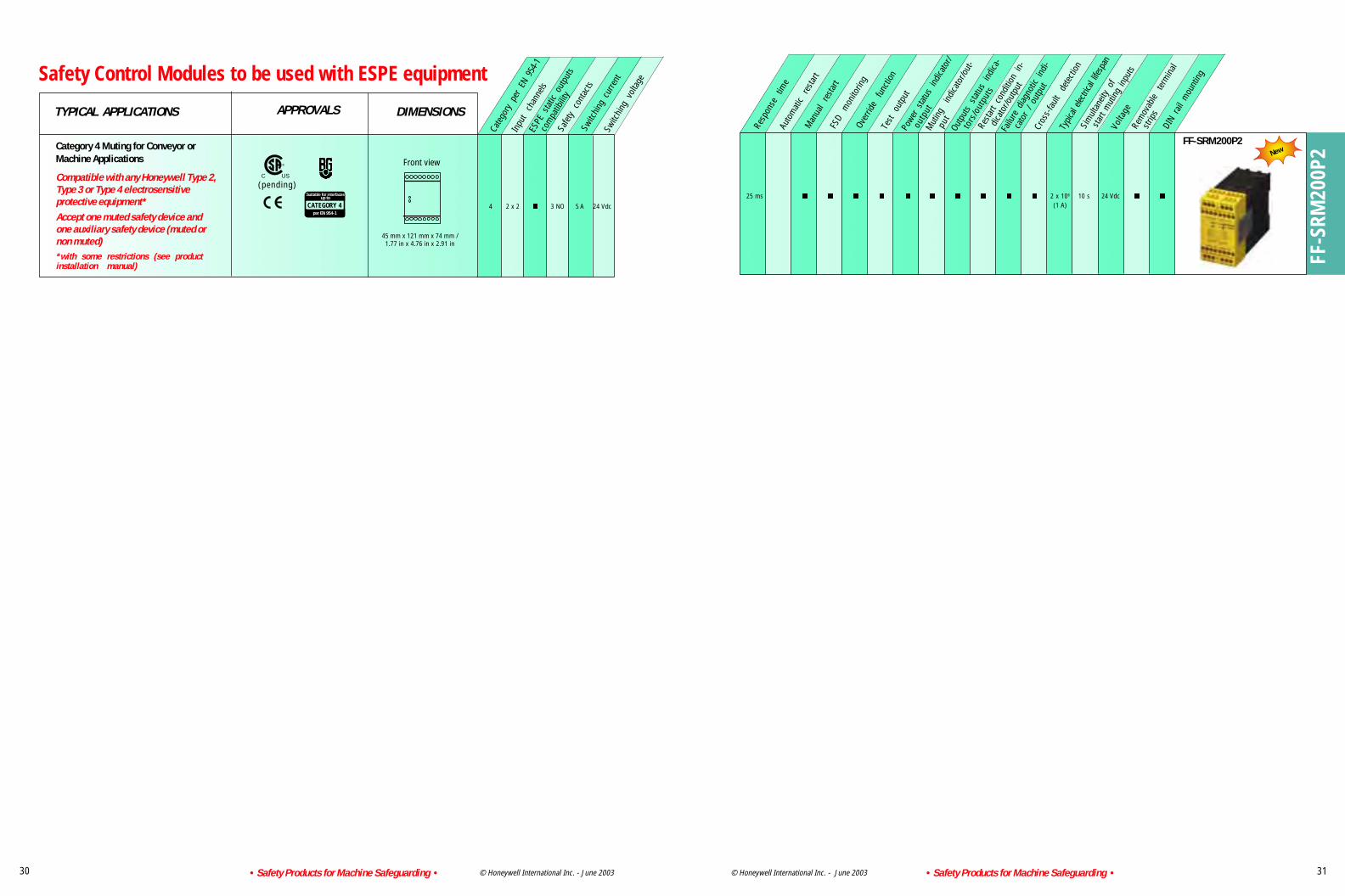
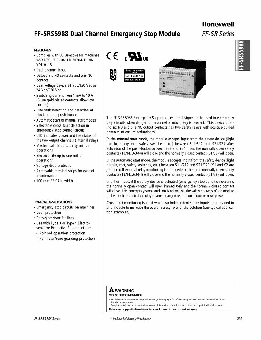
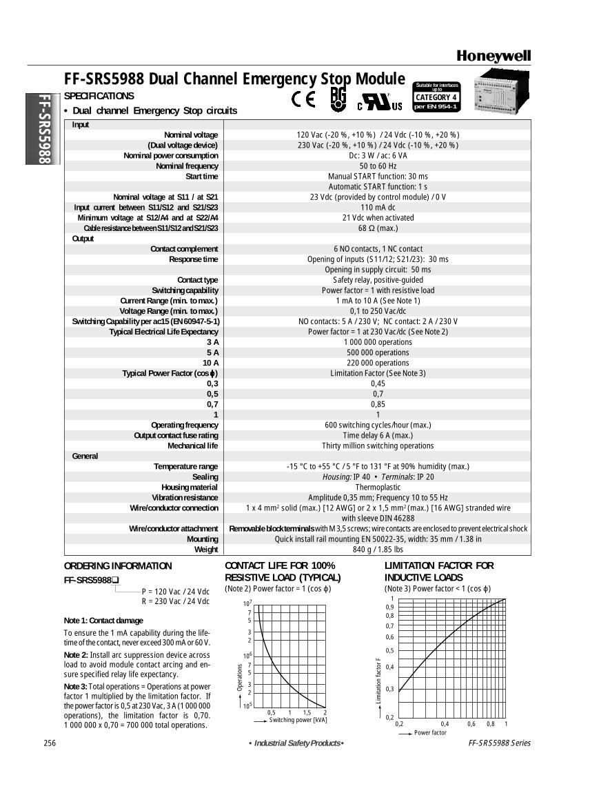
The FF-SRS5988 Emergency Stop modules are designed to be used in emergencystop circuits when danger to personnel or machinery is present. This device offer-ing six NO and one NC output contacts has two safety relays with positive-guidedcontacts to ensure redundancy.
In the manual start mode, the module accepts input from the safety device (lightcurtain, safety mat, safety switches, etc.) between S11/S12 and S21/S23 afteractivation of the push-button between S33 and S34; then, the normally open safetycontacts (13/14...63/64) will close and the normally closed contact (81/82) will open.
In the automatic start mode, the module accepts input from the safety device (lightcurtain, mat, safety switches, etc.) between S11/S12 and S21/S23 (Y1 and Y2 arejumpered if external relay monitoring is not needed); then, the normally open safetycontacts (13/14...63/64) will close and the normally closed contact (81/82) will open.
In either mode, if the safety device is actuated (emergency stop condition occurs),the normally open contact will open immediately and the normally closed contactwill close. This emergency stop condition is relayed via the safety contacts of the moduleto the machine control circuitry to arrest dangerous motion and/or remove power.
Cross fault monitoring is used when two independent safety inputs are provided tothis module to increase the overall safety level of the solution (see typical applica-tion examples).
(Dual voltage device) 230 Vac (-20 %, +10 %) / 24 Vdc (-10 %, +20 %)Nominal power consumption Dc: 3 W / ac: 6 VA
Nominal frequency 50 to 60 HzStart time Manual START function: 30 ms
Automatic START function: 1 sNominal voltage at S11 / at S21 23 Vdc (provided by control module) / 0 V
Input current between S11/S12 and S21/S23 110 mA dcMinimum voltage at S12/A4 and at S22/A4 21 Vdc when activated
Cable resistance between S11/S12 and S21/S23 68 Ω (max.)Output
Contact complement 6 NO contacts, 1 NC contactResponse time Opening of inputs (S11/12; S21/23): 30 ms
Opening in supply circuit: 50 msContact type Safety relay, positive-guided
Switching capability Power factor = 1 with resistive loadCurrent Range (min. to max.) 1 mA to 10 A (See Note 1)Voltage Range (min. to max.) 0,1 to 250 Vac/dc
Switching Capability per ac15 (EN 60947-5-1) NO contacts: 5 A / 230 V; NC contact: 2 A / 230 VTypical Electrical Life Expectancy Power factor = 1 at 230 Vac/dc (See Note 2)
3 A 1 000 000 operations5 A 500 000 operations
10 A 220 000 operationsTypical Power Factor (cos ϕϕϕϕϕ) Limitation Factor (See Note 3)
0,3 0,450,5 0,70,7 0,85
1 1Operating frequency 600 switching cycles/hour (max.)
Output contact fuse rating Time delay 6 A (max.)Mechanical life Thirty million switching operations
GeneralTemperature range -15 ° C to +55 ° C / 5 ° F to 131 ° F at 90% humidity (max.)
Sealing Housing: IP 40 • Terminals: IP 20Housing material Thermoplastic
Vibration resistance Amplitude 0,35 mm; Frequency 10 to 55 HzWire/conductor connection 1 x 4 mm2 solid (max.) [12 AWG] or 2 x 1,5 mm2 (max.) [16 AWG] stranded wire
with sleeve DIN 46288Wire/conductor attachment Removable block terminals with M 3,5 screws; wire contacts are enclosed to prevent electrical shock
Mounting Quick install rail mounting EN 50022-35, width: 35 mm / 1.38 inWeight 840 g / 1.85 lbs
ORDERING INFORMATIONFF-SRS5988
P = 120 Vac / 24 VdcR = 230 Vac / 24 Vdc
Note 1: Contact damageTo ensure the 1 mA capability during the life-time of the contact, never exceed 300 mA or 60 V.Note 2: Install arc suppression device acrossload to avoid module contact arcing and en-sure specified relay life expectancy.Note 3: Total operations = Operations at powerfactor 1 multiplied by the limitation factor. Ifthe power factor is 0,5 at 230 Vac, 3 A (1 000 000operations), the limitation factor is 0,70.1 000 000 x 0,70 = 700 000 total operations.
CONTACT LIFE FOR 100%RESISTIVE LOAD (TYPICAL)(Note 2) Power factor = 1 (cos ϕ)
107
75
32
106
105
75
32
0,5 1 1,5 2Switching power [kVA]
Oper
atio
ns
Power factor0,2
0,2
0,3
0,4
0,5
0,6
0,7
0,80,9
1
0,4 0,6 0,8 1
Lim
itatio
n fa
ctor
F
FF-SRS5988 Series
FF-S
RS59
88
• Industrial Safety Products • 257
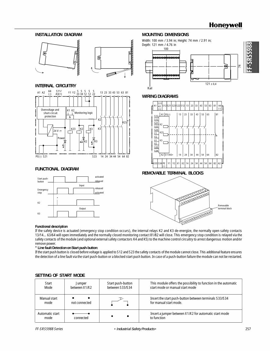
MOUNTING DIMENSIONSWidth: 100 mm / 3.94 in; Height: 74 mm / 2.91 in;Depth: 121 mm / 4.76 in
WIRING DIAGRAMS
REMOVABLE TERMINAL BLOCKS
INSTALLATION DIAGRAM
INTERNAL CIRCUITRY
FUNCTIONAL DIAGRAM
SETTING OF START MODE
Rail121 ± 0,4
74
100
PE(-) S23 64S21
K2K23
K2
&
K1
K3
PowerK2 K3
24 V ...
14 24 34 44 54 82
K3
K2K23
Overvoltage andshort-circuitprotection
Monitoring logic
23A1 A2 A4(-)
S11/A3(+) Y1 Y2 S
33S34
S12
S12
S22 13 33 43 53 63 81
A1
A1
K2
K23
K3
A2 14 24 34 44 54 64 82S11/A3+
13 23 33 43 53 63 81
S11A3(+)
S12
S12S12S21S22S23Y1Y2X1X2S33
S33 S34 Y1 Y2 X1 X2 14 24 34 44 54 64 82 A2PE(-)
PE(-)
S34
S21 S23 S22 S12 13 23 33 43 53 63 81 A4(-)
Removable terminal block
Start push-button
Emergencystop
K2
K3
Input
Output
released
activated
released
activated
*
Start Jumper Start push-button This module offers the possibility to function in the automaticMode between X1/X2 between S33/S34 start mode or manual start mode
Manual start Insert the start push-button between terminals S33/S34mode not connected for manual start mode.
Automatic start Insert a jumper between X1/X2 for automatic start modemode connected to function
Functional descriptionIf the safety device is actuated (emergency stop condition occurs), the internal relays K2 and K3 de-energize, the normally open safety contacts13/14… 63/64 will open immediately and the normally closed monitoring contact 81/82 will close. This emergency stop condition is relayed via thesafety contacts of the module (and optional external safety contactors K4 and K5) to the machine control circuitry to arrest dangerous motion and/orremove power.* Line fault Detection on Start push-button:If the start push button is closed before voltage is applied to S12 and S23 the safety contacts of the module cannot close. This additional feature ensuresthe detection of a line fault via the start push-button or a blocked start push button. In case of a push-button failure the module can not be restarted.
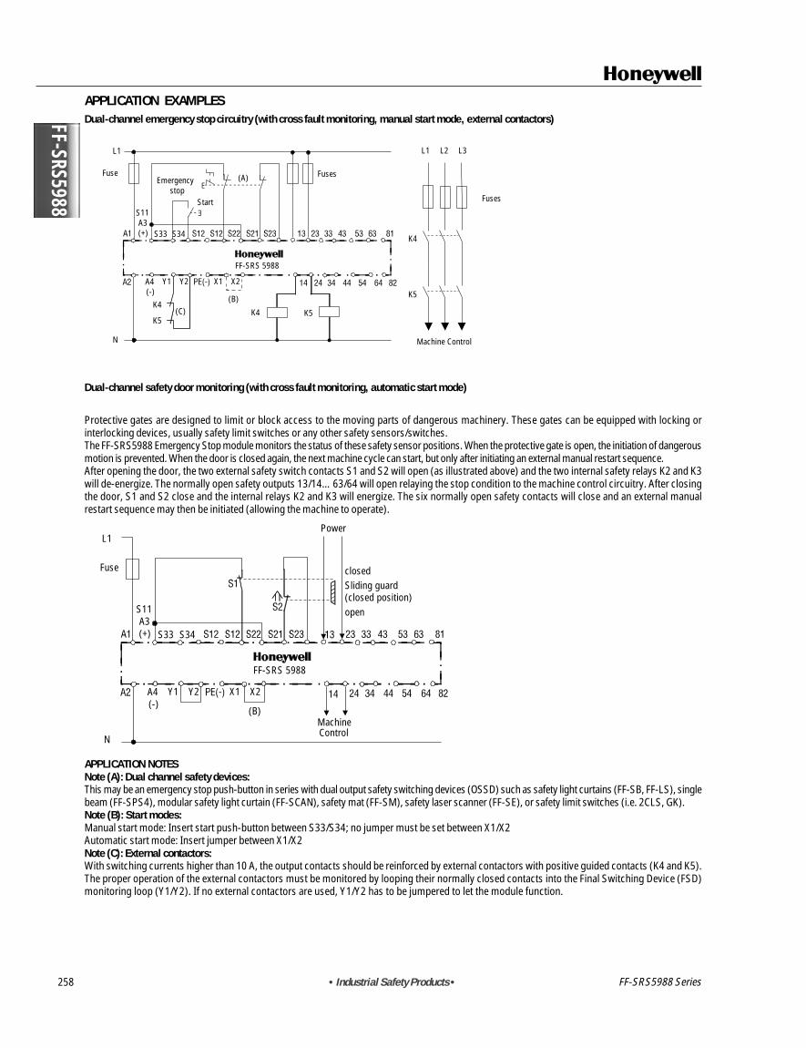
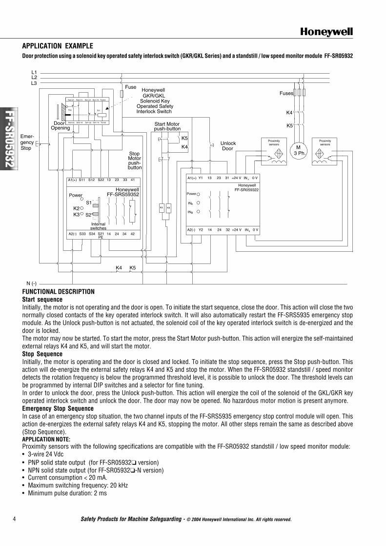
Protective gates are designed to limit or block access to the moving parts of dangerous machinery. These gates can be equipped with locking orinterlocking devices, usually safety limit switches or any other safety sensors/switches.The FF-SRS5988 Emergency Stop module monitors the status of these safety sensor positions. When the protective gate is open, the initiation of dangerousmotion is prevented. When the door is closed again, the next machine cycle can start, but only after initiating an external manual restart sequence.After opening the door, the two external safety switch contacts S1 and S2 will open (as illustrated above) and the two internal safety relays K2 and K3will de-energize. The normally open safety outputs 13/14… 63/64 will open relaying the stop condition to the machine control circuitry. After closingthe door, S1 and S2 close and the internal relays K2 and K3 will energize. The six normally open safety contacts will close and an external manualrestart sequence may then be initiated (allowing the machine to operate).
APPLICATION NOTESNote (A): Dual channel safety devices:This may be an emergency stop push-button in series with dual output safety switching devices (OSSD) such as safety light curtains (FF-SB, FF-LS), singlebeam (FF-SPS4), modular safety light curtain (FF-SCAN), safety mat (FF-SM), safety laser scanner (FF-SE), or safety limit switches (i.e. 2CLS, GK).Note (B): Start modes:Manual start mode: Insert start push-button between S33/S34; no jumper must be set between X1/X2Automatic start mode: Insert jumper between X1/X2Note (C): External contactors:With switching currents higher than 10 A, the output contacts should be reinforced by external contactors with positive guided contacts (K4 and K5).The proper operation of the external contactors must be monitored by looping their normally closed contacts into the Final Switching Device (FSD)monitoring loop (Y1/Y2). If no external contactors are used, Y1/Y2 has to be jumpered to let the module function.
! WARNINGMISUSE OF DOCUMENTATION• The information presented in this product sheet (or catalogue) is for reference only. DO NOT USE this document as system
installation information.• Complete installation, operation and maintenance information is to be referenced for each product.MISUSE OF PRODUCT• The FF-SRS59392 module is designed to be used with the Honeywell FF-SYA safety light curtain equipped with fail-safe solid state
outputs. The FF-SYA performs cross-fault detection between its outputs. The FF-SRS59392 module does not perform the cross-fault detection between its inputs. To ensure the highest safety category, do NOT use the FF-SRS59392 with any other equipment.For other equipment, use the FF-SRS5935 or FF-SRS5925 dual channel emergency stop module. Both modules perform the cross-fault detection between the safety device outputs.
Failure to comply with these instructions could result in death or serious injury.
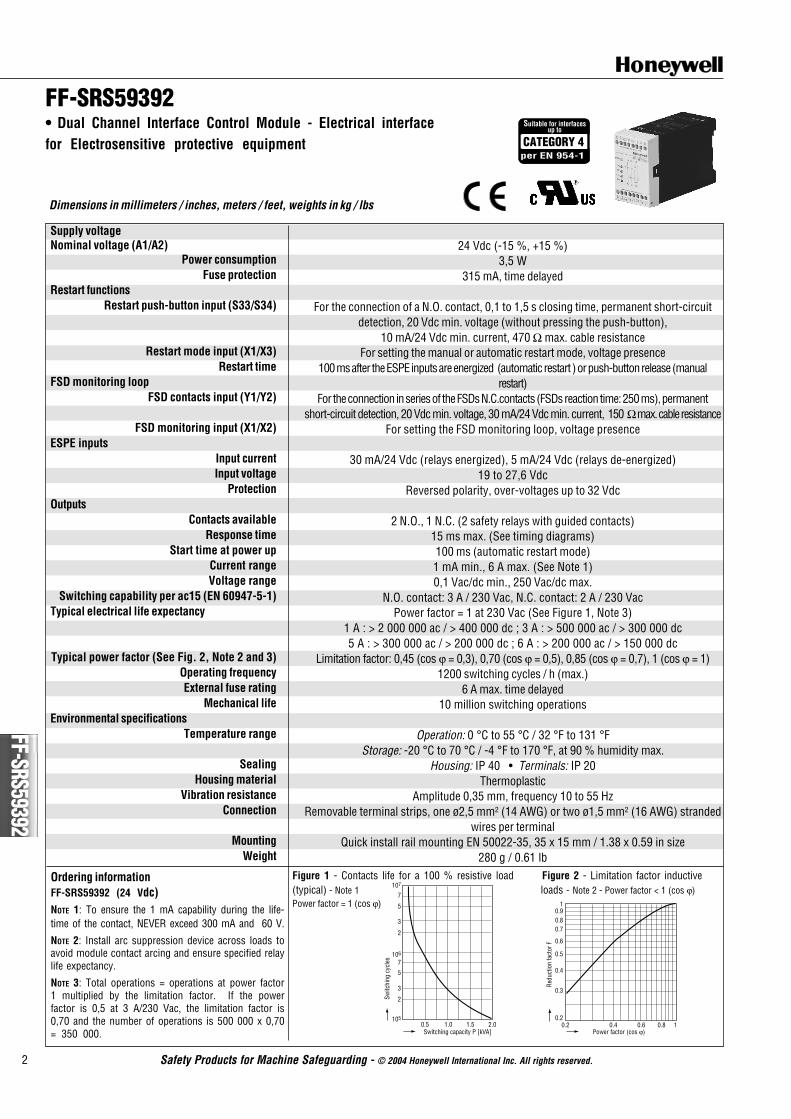
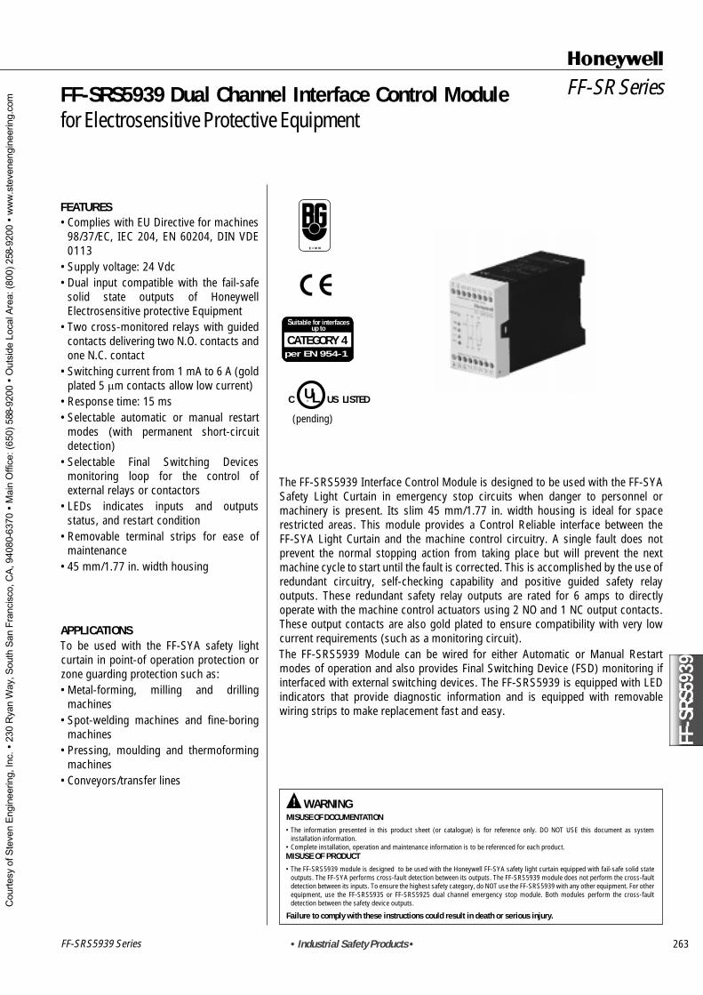
FF-SRS59392 Dual Channel Interface Control Modulefor Electrosensitive Protective Equipment
FEATURES• Complies with EU Directive for machines
98/37/EC, IEC 204, EN 60204, DIN VDE0113
• Supply voltage: 24 Vdc• Dual input compatible with the safety
static outputs of HoneywellElectrosensitive protective Equipment
• Two cross-monitored relays with guidedcontacts delivering two N.O. contactsand one N.C. contact
• Switching current from 1 mA to 6 A(gold plated 5 µm contacts allow lowcurrent)
• Response time: 15 ms• Selectable automatic or manual restart
modes (with permanent short-circuitdetection)
• Selectable Final Switching Devicesmonitoring loop for the control ofexternal relays or contactors
• LEDs indicates inputs and outputsstatus, and restart condition
• Removable terminal strips for ease ofmaintenance
• 45 mm / 1.77 in width housing
TYPICAL APPLICATIONSTo be used with the FF-SYA safety lightcurtain in point-of operation protection orzone guarding protection such as:• Metal-forming, milling and drilling
machines• Spot-welding machines and fine-boring
machines• Pressing, moulding and thermoforming
machines• Conveyors/transfer lines
The FF-SRS59392 Interface Control Module is designed to be used with the FF-SYASafety Light Curtain in emergency stop circuits when danger to personnel ormachinery is present. Its slim 45 mm / 1.77 in width housing is ideal for spacerestricted areas. This module provides a Control Reliable interface between theFF-SYA Light Curtain and the machine control circuitry. A single fault does notprevent the normal stopping action from taking place but will prevent the nextmachine cycle to start until the fault is corrected. This is accomplished by the use ofredundant circuitry, self-checking capability and positive guided safety relayoutputs. These redundant safety relay outputs are rated for 6 amps to directlyoperate with the machine control actuators using 2 NO and 1 NC output contacts.These output contacts are also gold plated to ensure compatibility with very lowcurrent requirements (such as a monitoring circuit).The FF-SRS59392 Module can be wired for either Automatic or Manual Restartmodes of operation and also provides Final Switching Device (FSD) monitoring ifinterfaced with external switching devices. The FF-SRS5939 is equipped with LEDindicators that provide diagnostic information and is equipped with removablewiring strips to make replacement fast and easy.
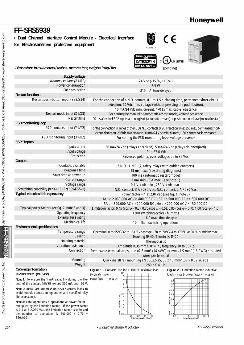
Switching capability per ac15 (EN 60947-5-1)Typical electrical life expectancy
Typical power factor (See Fig. 2, Note 2 and 3)Operating frequencyExternal fuse rating
Mechanical lifeEnvironmental specifications
Temperature range
SealingHousing material
Vibration resistanceConnection
MountingWeight
Ordering informationFF-SRS59392 (24 Vdc)NOTE 1: To ensure the 1 mA capability during the life-time of the contact, NEVER exceed 300 mA and 60 V.
NOTE 2: Install arc suppression device across loads toavoid module contact arcing and ensure specified relaylife expectancy.
NOTE 3: Total operations = operations at power factor1 multiplied by the limitation factor. If the powerfactor is 0,5 at 3 A/230 Vac, the limitation factor is0,70 and the number of operations is 500 000 x 0,70= 350 000.
24 Vdc (-15 %, +15 %)3,5 W
315 mA, time delayed
For the connection of a N.O. contact, 0,1 to 1,5 s closing time, permanent short-circuitdetection, 20 Vdc min. voltage (without pressing the push-button),
10 mA/24 Vdc min. current, 470 Ω max. cable resistanceFor setting the manual or automatic restart mode, voltage presence
100 ms after the ESPE inputs are energized (automatic restart ) or push-button release (manualrestart)
For the connection in series of the FSDs N.C.contacts (FSDs reaction time: 250 ms), permanentshort-circuit detection, 20 Vdc min. voltage, 30 mA/24 Vdc min. current, 150 Ω max. cable resistance
For setting the FSD monitoring loop, voltage presence
2 N.O., 1 N.C. (2 safety relays with guided contacts)15 ms max. (See timing diagrams)100 ms (automatic restart mode)1 mA min., 6 A max. (See Note 1)0,1 Vac/dc min., 250 Vac/dc max.
N.O. contact: 3 A / 230 Vac, N.C. contact: 2 A / 230 VacPower factor = 1 at 230 Vac (See Figure 1, Note 3)
1 A : > 2 000 000 ac / > 400 000 dc ; 3 A : > 500 000 ac / > 300 000 dc5 A : > 300 000 ac / > 200 000 dc ; 6 A : > 200 000 ac / > 150 000 dc
3. Normal operation: emergency stop condition is removedand the FSDs monitoring loops opens.
4. Failure on the FSDs: emergency stop condition occurs andthe FSDs monitoring loop remains open.
5. Failure on the FSDs: emergency stop condition is removedbut the machine cannot restart.
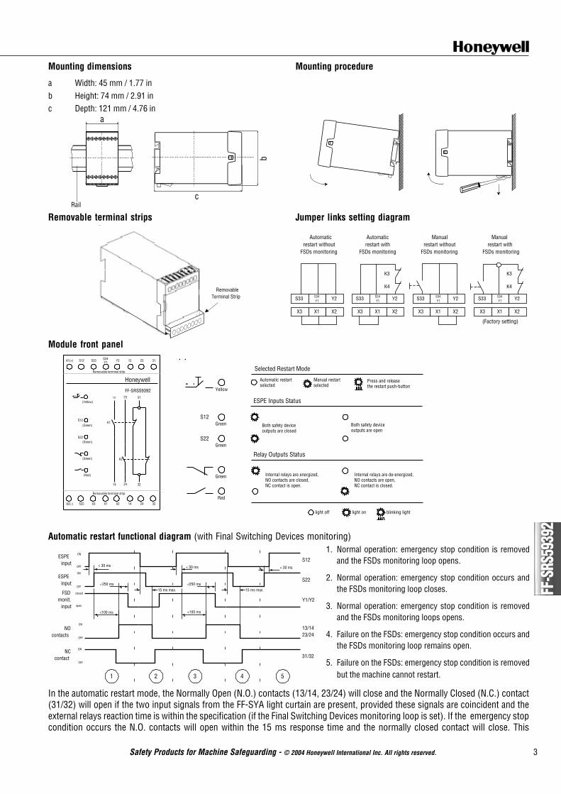
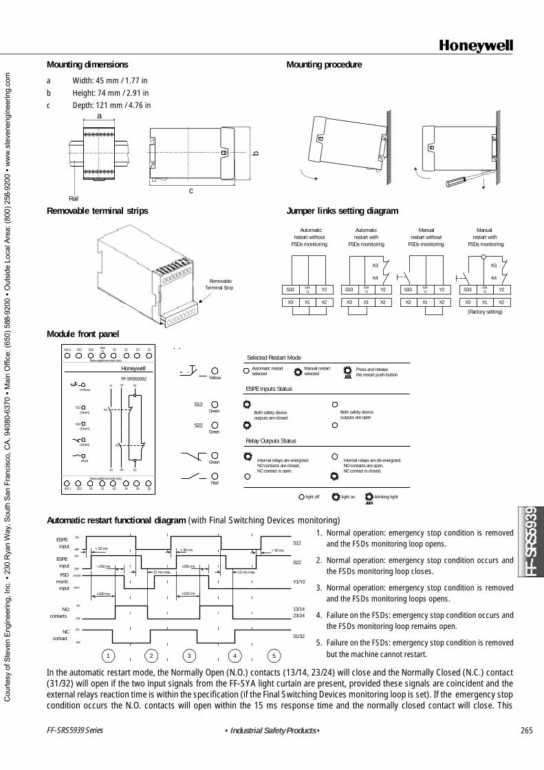
In the automatic restart mode, the Normally Open (N.O.) contacts (13/14, 23/24) will close and the Normally Closed (N.C.) contact(31/32) will open if the two input signals from the FF-SYA light curtain are present, provided these signals are coincident and theexternal relays reaction time is within the specification (if the Final Switching Devices monitoring loop is set). If the emergency stopcondition occurs the N.O. contacts will open within the 15 ms response time and the normally closed contact will close. This
emergency stop condition is relayed via the safety contacts of the module to the machine control circuitry to arrest dangerousmotion and/or remove power.The module will not restart if the FSD monitoring loop remains permanently open, or remains closedfor more than 250 ms or permanently.
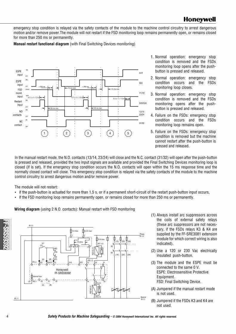
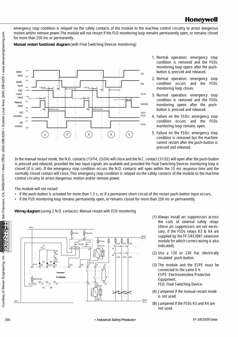
Manual restart functional diagram (with Final Switching Devices monitoring)
1. Normal operation: emergency stopcondition is removed and the FSDsmonitoring loop opens after the push-button is pressed and released.
2. Normal operation: emergency stopcondition occurs and the FSDsmonitoring loop closes.
3. Normal operation: emergency stopcondition is removed and the FSDsmonitoring opens after the push-button is pressed and released.
4. Failure on the FSDs: emergency stopcondition occurs and the FSDsmonitoring loop remains open.
5. Failure on the FSDs: emergency stopcondition is removed but the machinecannot restart after the push-button ispressed and released.
In the manual restart mode, the N.O. contacts (13/14, 23/24) will close and the N.C. contact (31/32) will open after the push-buttonis pressed and released, provided the two input signals are available and provided the Final Switching Devices monitoring loop isclosed (if is set). If the emergency stop condition occurs the N.O. contacts will open within the 15 ms response time and thenormally closed contact will close. This emergency stop condition is relayed via the safety contacts of the module to the machinecontrol circuitry to arrest dangerous motion and/or remove power.
The module will not restart: if the push-button is actuated for more than 1,5 s, or if a permanent short-circuit of the restart push-button input occurs, if the FSD monitoring loop remains permanently open, or remains closed for more than 250 ms or permanently.
(1) Always install arc suppressors acrossthe coils of external safety relays(these arc suppressors are not neces-sary, if the FSDs relays K3 & K4 aresupplied by the FF-SRE3081 extensionmodule for which correct wiring is alsoindicated).
(2) Use a 120 or 230 Vac electricallyinsulated push-button.
(3) The module and the ESPE must beconnected to the same 0 V.ESPE: Electrosensitive ProtectiveEquipment.FSD: Final Switching Device.
(A) Jumpered if the manual restart modeis not used.
(B) Jumpered if the FSDs K3 and K4 arenot used.
Warranty and remedyHoneywell warrants goods of its manufacture as being free of defectivematerials and faulty workmanship. Contact your local sales office for war-ranty information. If warranted goods are returned to Honeywell duringthe period of coverage, Honeywell will repair or replace without chargethose items it finds defective. The foregoing is Buyer’s sole remedy andis in lieu of all other warranties, expressed or implied, including thoseof merchantability and fitness for a particular purpose.While we provide application assistance, personally, through our literatureand the Honeywell web site, it is up to the customer to determine thesuitability of the product in the application.
Honeywell11 West Spring StreetFreeport, Illinois 61032USA
Honeywell21 Chemin du Vieux Chêne38240 Meylan CedexFrance
Specifications may change at any time without notice. The information wesupply is believed to be accurate and reliable as of this printing. However,we assume no responsibility for its use.
Sales and ServiceHoneywell serves its customers through a worldwide network of salesoffices and distributors. For application assistance,current specifications,pricing or name of the nearest Authorised Distributor, contact a nearbysales office or:INTERNET: www.honeywell.com/sensing
! WARNINGMISUSE OF DOCUMENTATION• The information presented in this product sheet (or catalogue) is for reference only. DO NOT USE this document as system
installation information.• Complete installation, operation and maintenance information is provided in the instructions supplied with each product.
Failure to comply with these instructions could result in death or serious injury.
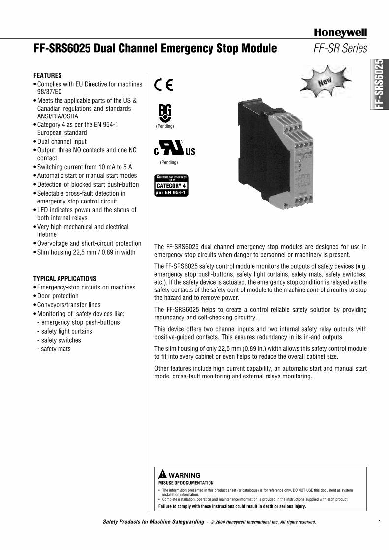
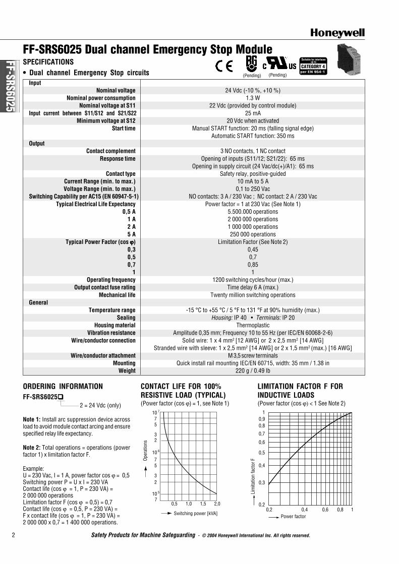
The FF-SRS6025 dual channel emergency stop modules are designed for use inemergency stop circuits when danger to personnel or machinery is present.
The FF-SRS6025 safety control module monitors the outputs of safety devices (e.g.emergency stop push-buttons, safety light curtains, safety mats, safety switches,etc.). If the safety device is actuated, the emergency stop condition is relayed via thesafety contacts of the safety control module to the machine control circuitry to stopthe hazard and to remove power.
The FF-SRS6025 helps to create a control reliable safety solution by providingredundancy and self-checking circuitry.
This device offers two channel inputs and two internal safety relay outputs withpositive-guided contacts. This ensures redundancy in its in-and outputs.
The slim housing of only 22,5 mm (0.89 in.) width allows this safety control moduleto fit into every cabinet or even helps to reduce the overall cabinet size.
Other features include high current capability, an automatic start and manual startmode, cross-fault monitoring and external relays monitoring.
• Dual channel input• Output: three NO contacts and one NC
contact• Switching current from 10 mA to 5 A• Automatic start or manual start modes• Detection of blocked start push-button• Selectable cross-fault detection in
emergency stop control circuit• LED indicates power and the status of
both internal relays• Very high mechanical and electrical
lifetime• Overvoltage and short-circuit protection• Slim housing 22,5 mm / 0.89 in width
TYPICAL APPLICATIONS• Emergency-stop circuits on machines• Door protection• Conveyors/transfer lines• Monitoring of safety devices like:
Nominal power consumption 1.3 WNominal voltage at S11 22 Vdc (provided by control module)
Input current between S11/S12 and S21/S22 25 mAMinimum voltage at S12 20 Vdc when activated
Start time Manual START function: 20 ms (falling signal edge)Automatic START function: 350 ms
OutputContact complement 3 NO contacts, 1 NC contact
Response time Opening of inputs (S11/12; S21/22): 65 msOpening in supply circuit (24 Vac/dc(+)/A1): 65 ms
Contact type Safety relay, positive-guidedCurrent Range (min. to max.) 10 mA to 5 AVoltage Range (min. to max.) 0,1 to 250 Vac
Switching Capability per AC15 (EN 60947-5-1) NO contacts: 3 A / 230 Vac ; NC contact: 2 A / 230 VacTypical Electrical Life Expectancy Power factor = 1 at 230 Vac (See Note 1)
0,5 A 5.500.000 operations1 A 2 000 000 operations2 A 1 000 000 operations5 A 250 000 operations
Typical Power Factor (cos ϕϕϕϕϕ) Limitation Factor (See Note 2)0,3 0,450,5 0,70,7 0,85
1 1Operating frequency 1200 switching cycles/hour (max.)
Output contact fuse rating Time delay 6 A (max.)Mechanical life Twenty million switching operations
GeneralTemperature range -15 °C to +55 °C / 5 °F to 131 °F at 90% humidity (max.)
Sealing Housing: IP 40 • Terminals: IP 20Housing material Thermoplastic
Vibration resistance Amplitude 0,35 mm; Frequency 10 to 55 Hz (per IEC/EN 60068-2-6)Wire/conductor connection Solid wire: 1 x 4 mm2 [12 AWG] or 2 x 2,5 mm2 [14 AWG]
Stranded wire with sleeve: 1 x 2,5 mm2 [14 AWG] or 2 x 1,5 mm2 (max.) [16 AWG]Wire/conductor attachment M 3,5 screw terminals
Mounting Quick install rail mounting IEC/EN 60715, width: 35 mm / 1.38 inWeight 220 g / 0.49 lb
ORDERING INFORMATIONFF-SRS6025!!!!!
2 = 24 Vdc (only)
Note 1: Install arc suppression device acrossload to avoid module contact arcing and ensurespecified relay life expectancy.
Note 2: Total operations = operations (powerfactor 1) x limitation factor F.
Example:U = 230 Vac, I = 1 A, power factor cos ϕ = 0,5Switching power P = U x I = 230 VAContact life (cos ϕ = 1, P = 230 VA) =2 000 000 operationsLimitation factor F (cos ϕ = 0,5) = 0,7Contact life (cos ϕ = 0,5, P = 230 VA) =F x contact life (cos ϕ = 1, P = 230 VA) =2 000 000 x 0,7 = 1 400 000 operations.
CONTACT LIFE FOR 100%RESISTIVE LOAD (TYPICAL)(Power factor (cos ϕ) = 1, see Note 1)
Power factor0,2
0,2
0,3
0,4
0,5
0,6
0,7
0,80,9
1
0,4 0,6 0,8 1
Lim
itatio
n fa
ctor
F
(Pending)
1075
32
7
70,5 1,0 1,5 2,0
5
Oper
atio
ns
Switching power [kVA]
32
7
10 6
10 5
FF-S
RS60
25
3
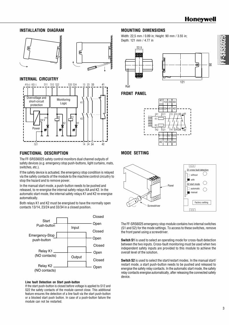
MOUNTING DIMENSIONSWidth: 22,5 mm / 0.89 in; Height: 90 mm / 3.55 in;Depth: 121 mm / 4.77 in
FRONT PANEL
MODE SETTING
INSTALLATION DIAGRAM
INTERNAL CIRCUITRY
FUNCTIONAL DESCRIPTIONThe FF-SRS56025 safety control monitors dual channel outputs ofsafety devices (e.g. emergency stop push-buttons, light curtains, mats,switches, etc.).If the safety device is actuated, the emergency stop condition is relayedvia the safety contacts of the module to the machine control circuitry tostop the hazard and to remove power.In the manual start mode, a push-button needs to be pushed andreleased, to re-energise the internal safety relays KA and K2. In theautomatic start mode, the internal safety relays K1 and K2 re-energiseautomatically.Both relays K1 and K2 must be energised to have the normally opencontacts 13/14, 23/24 and 33/34 in a closed position.
4133
34 42
Overvoltage andshort-circuitprotection
MonitoringLogic
Power
24 V
A1(+)
13
S33S34 41 42
23 33
S11S12
A2 14 24 34
33 41
4234
S21S22
S1 cross fault detection
S2 start mode
without
with
automatic
manual
Factory setting
StartPush-button
Relay K1(NO contacts)
Input
Output
Relay K2(NO contacts)
Emergency-Stoppush-button
Closed
Open
Closed
Open
Closed
Open
Closed
Open
The FF-SRS6025 emergency stop module contains two internal switches(S1 and S2) for the mode settings. To access to these switches, removethe front panel using a screwdriver.
Switch S1 is used to select an operating mode for cross-fault detectionbetween the two inputs. Cross-fault monitoring must be used when twoindependent safety inputs are provided to this module to achieve theoverall level of the solution.
Switch S2 is used to select the start/restart modes. In the manual start/restart mode, a start push-button needs to be pushed and released toenergise the safety relay contacts. In the automatic start mode, the safetyrelay contacts energise automatically, after releasing the connected safetydevice.
Line fault Detection on Start push-buttonIf the start push-button is closed before voltage is applied to S12 andS22 the safety contacts of the module cannot close. This additionalfeature ensures the detection of a line fault via the start push-buttonor a blocked start push button. In case of a push-button failure themodule can not be restarted.
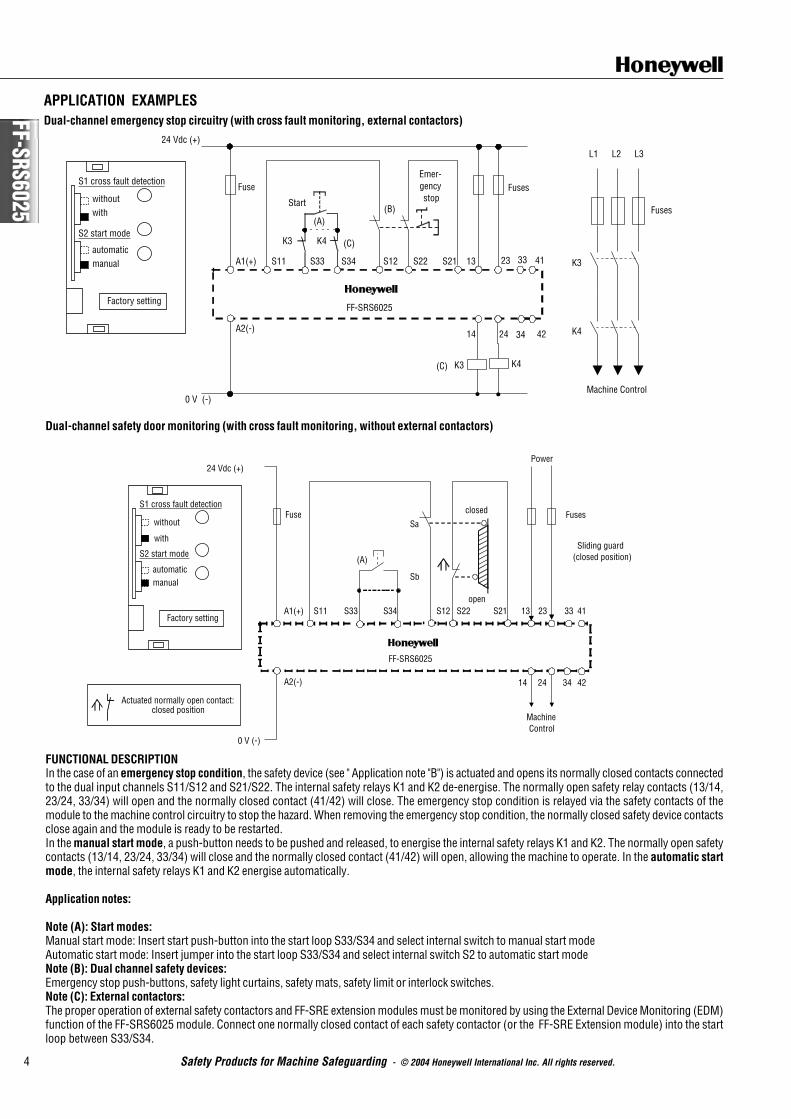
Dual-channel safety door monitoring (with cross fault monitoring, without external contactors)
FUNCTIONAL DESCRIPTIONIn the case of an emergency stop condition, the safety device (see " Application note "B") is actuated and opens its normally closed contacts connectedto the dual input channels S11/S12 and S21/S22. The internal safety relays K1 and K2 de-energise. The normally open safety relay contacts (13/14,23/24, 33/34) will open and the normally closed contact (41/42) will close. The emergency stop condition is relayed via the safety contacts of themodule to the machine control circuitry to stop the hazard. When removing the emergency stop condition, the normally closed safety device contactsclose again and the module is ready to be restarted.In the manual start mode, a push-button needs to be pushed and released, to energise the internal safety relays K1 and K2. The normally open safetycontacts (13/14, 23/24, 33/34) will close and the normally closed contact (41/42) will open, allowing the machine to operate. In the automatic startmode, the internal safety relays K1 and K2 energise automatically.
Application notes:
Note (A): Start modes:Manual start mode: Insert start push-button into the start loop S33/S34 and select internal switch to manual start modeAutomatic start mode: Insert jumper into the start loop S33/S34 and select internal switch S2 to automatic start modeNote (B): Dual channel safety devices:Emergency stop push-buttons, safety light curtains, safety mats, safety limit or interlock switches.Note (C): External contactors:The proper operation of external safety contactors and FF-SRE extension modules must be monitored by using the External Device Monitoring (EDM)function of the FF-SRS6025 module. Connect one normally closed contact of each safety contactor (or the FF-SRE Extension module) into the startloop between S33/S34.
Warranty and remedyHoneywell warrants goods of its manufacture as being free of defectivematerials and faulty workmanship. Contact your local sales office forwarranty information. If warranted goods are returned to Honeywellduring the period of coverage, Honeywell will repair or replace withoutcharge those items it finds defective. The foregoing is Buyer’s sole rem-edy and is in lieu of all other warranties, expressed or implied, in-cluding those of merchantability and fitness for a particular pur-pose.While we provide application assistance, personally, through our litera-ture and the Honeywell web site, it is up to the customer to determinethe suitability of the product in the application.
Honeywell11 West Spring StreetFreeport, Illinois 61032USA
Honeywell21 Chemin du Vieux Chêne38240 Meylan CedexFrance
Specifications may change at any time without notice. The informationwe supply is believed to be accurate and reliable as of this printing. How-ever, we assume no responsibility for its use.
Sales and ServiceHoneywell serves its customers through a worldwide network of salesoffices and distributors. For application assistance,current specifications,pricing or name of the nearest Authorised Distributor, contact a nearbysales office or:INTERNET: www.honeywell.com/sensing
! WARNINGMISUSE OF DOCUMENTATION• The information presented in this product sheet (or catalogue) is for reference only. DO NOT USE this document as system
installation information.• Complete installation, operation and maintenance information is provided in the instructions supplied with each product.
Failure to comply with these instructions could result in death or serious injury.
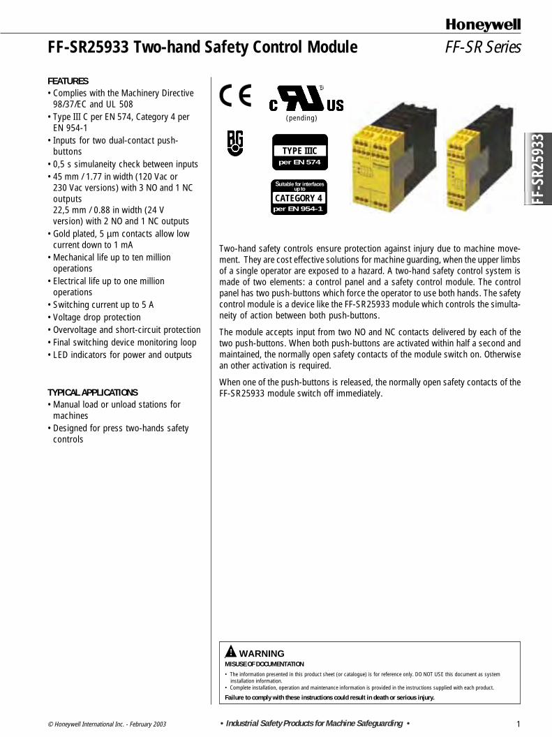
Two-hand safety controls ensure protection against injury due to machine move-ment. They are cost effective solutions for machine guarding, when the upper limbsof a single operator are exposed to a hazard. A two-hand safety control system ismade of two elements: a control panel and a safety control module. The controlpanel has two push-buttons which force the operator to use both hands. The safetycontrol module is a device like the FF-SR25933 module which controls the simulta-neity of action between both push-buttons.
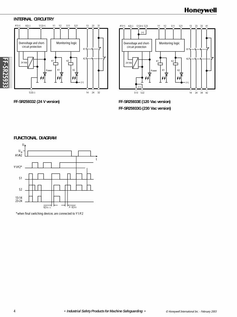
The module accepts input from two NO and NC contacts delivered by each of thetwo push-buttons. When both push-buttons are activated within half a second andmaintained, the normally open safety contacts of the module switch on. Otherwisean other activation is required.
When one of the push-buttons is released, the normally open safety contacts of theFF-SR25933 module switch off immediately.
TYPE IIICper EN 574
FF-SR SeriesFF-SR25933 Two-hand Safety Control Module
FEATURES• Complies with the Machinery Directive
98/37/EC and UL 508• Type III C per EN 574, Category 4 per
EN 954-1• Inputs for two dual-contact push-
buttons• 0,5 s simulaneity check between inputs• 45 mm / 1.77 in width (120 Vac or
230 Vac versions) with 3 NO and 1 NCoutputs22,5 mm / 0.88 in width (24 Vversion) with 2 NO and 1 NC outputs
• Gold plated, 5 µm contacts allow lowcurrent down to 1 mA
• Mechanical life up to ten millionoperations
• Electrical life up to one millionoperations
• Switching current up to 5 A• Voltage drop protection• Overvoltage and short-circuit protection• Final switching device monitoring loop• LED indicators for power and outputs
TYPICAL APPLICATIONS• Manual load or unload stations for
SPECIFICATIONS• Two-hand Safety Control for single operation protection
Input Nominal voltage 120 Vac (-15 %, +10 %), 230 Vac (-15 %, +10 %), 24 Vdc (-10 %, +10 %) and 24 Vac (-15 %, +10 %)Nominal consumption 120 Vac or 230 Vac: 4 VA; 24 V: 2,3 W
Nominal frequency 50 Hz to 60 HzNominal input current through 50 mA (NO contact), 20 mA (NC contact) (cable length must not exceed 30 m / 98 ft
S11/S12, S11/S13, S21/S22 and S21/S23 and must be routed separately from power cables)Time required for simultaneous contact closure
S11/S12 and S21/S22 0,5 sRecovery time 1 s
Output Contact complement 2 NO, 1 NC contacts (24 Vdc version); 3 NO, 1 NC contacts (120 Vac or 230 Vac versions)Contact type Safety relay, positive-guided
ON response time 40 ms (to energize relays)OFF response time 15 ms (to de-energize relays)
Switching Capability Power factor = 1 with resistive loadCurrent Range (min. to max.) 1 mA to 5 A (See Note 1)Voltage Range (min. to max.) 0,1 to 250 Vac/dc
Switching capability (per AC15: EN 60947-5-1) NO contact: 5 A / 250 VacTypical Electrical Life Expectancy Power factor = 1 at 230 Vac (See Note 2)
1 A 2 000 000 operations2 A 1 000 000 operations5 A 220 000 operations
Typical Power Factor (cos ϕ ϕ ϕ ϕ ϕ) Limitation Factor (See Note 3)0,3 0,450,5 0,700,7 0,85
1 1Mechanical life Ten million switching operations
Fuse Rating 6 A time delayedGeneral Temperature range -15 ° C to +55 ° C / 5 ° F to 131 ° F at max. 90 % humidity
Sealing Housing: IP 40 • Terminals: IP 20Housing material Thermoplastic
Vibration resistance Amplitude 0,35 mm; Frequency 10 Hz to 55 HzConductor connection 1 x 4 mm2 solid (max.) [12 AWG] or 2 x 1,5 mm2 (max.) [16 AWG]
Stranded wire with sleeve DIN 46288Conductor attachment M 3,5 screws terminals; wire contacts are enclosed to prevent electrical shock
Mounting Quick install rail mounting EN 50022-35Indication LED "power supply": ON when operating voltage applied
LED K1: ON when relay K1 activeLED K2: ON when relay K2 active
Weight 200 g / 0.44 lb (24 V version) ; 400 g / 0.88 lb (120 Vac or 230 Vac versions)
ORDERING INFORMATIONFF-SR25933 o
Voltage:2 = 24 Vdc/24 VacE = 120 VacG = 230 Vac
Note 1: To ensure the 1 mA capability duringthe lifetime of the contact, NEVERexceed 300 mA and 60 V.Note 2: Install arc suppression device acrossload to avoid module contact arcing and en-sure specified relay life expectancy.Note 3: Total operations = Operations atpower factor 1 multiplied by the limitationfactor. If the power factor is 0,5 at 230 Vac, 2 A(1 000 000 operations), the limitation factor is0,70.Total operations:1 000 000 x 0,70 = 700 000.
107
75
32
106
105
75
32
0,5 1 1,5 2Switching Power [kVA]
Oper
atio
ns
CONTACT LIFE FOR 100 %RESISTIVE LOAD (TYPICAL)Power factor = 1 (cos ϕ)
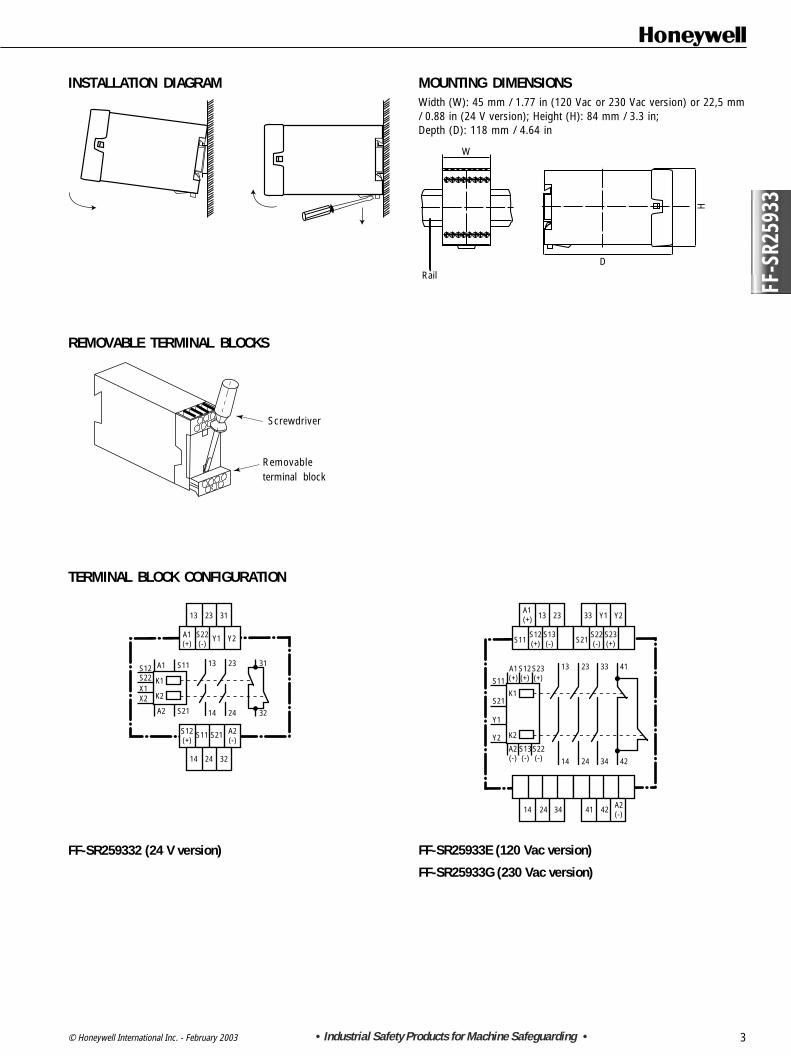
MOUNTING DIMENSIONSWidth (W): 45 mm / 1.77 in (120 Vac or 230 Vac version) or 22,5 mm/ 0.88 in (24 V version); Height (H): 84 mm / 3.3 in;Depth (D): 118 mm / 4.64 in
RailD
H
W
INSTALLATION DIAGRAM
TERMINAL BLOCK CONFIGURATION
13
A1(+)
S12(+)
A2(-)
S11 S21
S22(-)
Y1 Y2
23 31
14 24 32
13 23
14 24
31
32
S11A1
S21
K1
K2
A2
S12S22X1X2
A1(+)
S11S12(+)
S13(-)
13 23 33
S22(-)
S23(+)
Y1 Y2
13 23
14 24
33
34
41
42
A1(+)
A2(-)
S13(-)
S22(-)
S12(+)
S23(+)
K1
K2
S11
S21
Y1
Y2
S21
14 24 34 41 42 A2(-)
FF-SR259332 (24 V version) FF-SR25933E (120 Vac version)
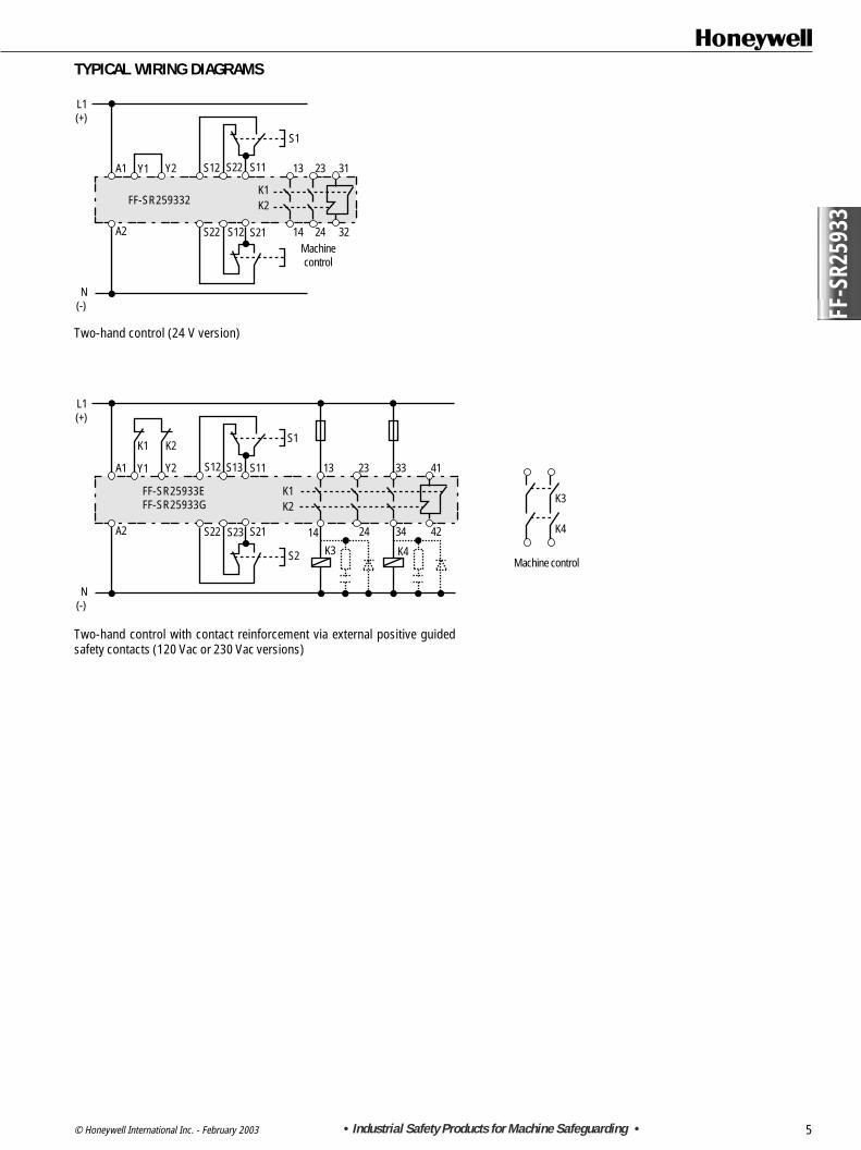
Two-hand control with contact reinforcement via external positive guidedsafety contacts (120 Vac or 230 Vac versions)
L1(+)
A1
A2
N(-)
FF-SR25933EFF-SR25933G
Y1 Y2
K1 K2
S12 S13 S11
Machine control
13
S1
S2 K3 K4
23
S22 S23 S21 14 24
33 41
34 42
K3
K4
K1K2
L1(+)
A1
A2
N(-)
FF-SR259332
Y1 Y2 S12 S22 S11 13
S1
Machinecontrol
K1K2
23 31
S22 S12 S21 14 24 32
Warranty and remedyHoneywell warrants goods of its manufacture as being free of defectivematerials and faulty workmanship. Contact your local sales office for war-ranty information. If warranted goods are returned to Honeywell duringthe period of coverage, Honeywell will repair or replace without chargethose items it finds defective. The foregoing is Buyer’s sole remedy and isin lieu of all other warranties, expressed or implied, including those ofmerchantability and fitness for a particular purpose.While we provide application assistance, personally, through our literatureand the Honeywell web site, it is up to the customer to determine thesuitability of the product in the application.
Honeywell11 West Spring StreetFreeport, Illinois 61032USA
Honeywell21 Chemin du Vieux Chêne38240 Meylan CedexFrance
Specifications may change at any time without notice. The information wesupply is believed to be accurate and reliable as of this printing. However,we assume no responsibility for its use.
Sales and ServiceHoneywell serves its customers through a worldwide network of salesoffices and distributors. For application assistance,current specifications,pricing or name of the nearest Authorised Distributor, contact a nearbysales office or:INTERNET: www.honeywell.com/sensing
! WARNINGMISUSE OF DOCUMENTATION• The information presented in this product sheet (or catalogue) is for reference only. DO NOT USE this document as system
installation information.• Complete installation, operation and maintenance information is provided in the instructions supplied with each product.
Failure to comply with these instructions could result in death or serious injury.
FF-S
R259
80
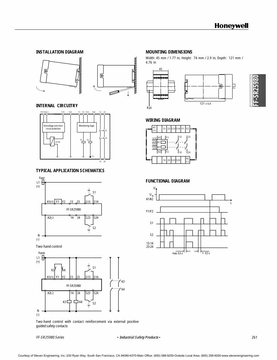
Two-hand safety controls ensure protection against hand injury due to dangerousmachine movement. A two-hand safety control system is made up of two elements:a control board and a safety control module. The control board has two controldevices that force the use of two-hand activation simultaneously. The safety controlelement is a device like the FF-SR25980 two-hand safety module. This control mod-ule relay is linked to the control board and is located in an enclosure.
The module will accept input from the two control devices (between S13/S14 andS23/S24) if Y1/Y2 are jumpered (or closed). When both input contacts close withinhalf a second and remain closed, the two normally open safety contacts (13/14 and23/24) will close. If these input contacts fail to close within half a second, or ifpower has been removed, another activation is required.
When one of the input contacts opens, the two normally open safety contacts of theFF-SR25980 module will open immediately.
FF-SR25980 Series
TYPE IIIAper EN 574
FF-SR SeriesFF-SR25980 Two-hand Safety Module
FEATURES• Complies with the Machinery Directive
98/37/EC and UL 508• Type 3 A per EN 574• Gold plated, 5 µm contacts 3 A allow low
current• Mechanical life up to ten million opera-
tions• Electrical life up to one million opera-
tions• Switching current up to 10 A• Voltage drop protection• 45 mm / 1.77 in width
TYPICAL APPLICATIONS• Secondary protection for robotics
Courtesy of Steven Engineering, Inc.-230 Ryan Way, South San Francisco, CA 94080-6370-Main Office: (650) 588-9200-Outside Local Area: (800) 258-9200-www.stevenengineering.com
SPECIFICATIONS• Two-hand Safety Control for hand injury protection
Input Nominal voltage 120 Vac (-15%, +10%), 230 Vac (-20%, +10%), 24 Vdc (-10%, +10%)Nominal consumption 120 and 230 Vac: 4 VA; 24 Vdc: 2,5 W
Nominal frequency 50 to 60 HzNominal voltage between S13/S14 and S23/S24 24 Vdc with 35 mA current; control line length must not exceed 30 m / 98 ft
and must be routed separately from power cablesTime required for simultaneous contact
closure S13/S14 and S23/S24 0,5 s
Output Contact complement 2 NO contactsContact type Safety relay, positive-guided
Response time Activation/deactivation by inputs S13/S14 and S23/S24: 30 msSwitching Capability Power factor = 1 with resistive load
Current Range (min. to max.) 1 mA to 10 A (See Note 1)Voltage Range (min. to max.) 0,1 to 250 Vac/dc
Switching capability (per ac15: EN 60947-5.1) NO contact: 5 A / 250 VacTypical Electrical Life Expectancy Power factor = 1 at 230 Vac/dc (See Note 2)
3 A 1 000 000 operations5 A 500 000 operations
10 A 220 000 operationsTypical Power Factor (cos ϕ ϕ ϕ ϕ ϕ) Limitation Factor (See Note 3)
0,3 0,450,5 0,700,7 0,85
1 1Mechanical life Ten million switching operations
Fuse Rating 6 A time delayedGeneral
Temperature range -15 °C to +55 °C / 5 °F to 131 °F at max. 90% humiditySealing Housing: IP 40 • Terminals: IP 20
Housing material ThermoplasticVibration resistance Amplitude 0,35 mm; Frequency 10 to 55 Hz
Conductor connection 1 x 4 mm2 solid (max.) [12 AWG] or 2 x 1,5 mm2 (max.) [16 AWG]stranded wire with sleeve DIN 46288
Conductor attachment M 3,5 screws terminals; wire contacts are enclosed to prevent electrical shockMounting Quick install rail mounting EN 50022-35
Weight 410 g / 0.90 lb
ORDERING INFORMATIONFF-SR25980
Voltage:2 = 24 VdcE = 120 VacG = 230 Vac
Note 1: To ensure the 1 mA capability duringthe lifetime of the contact, NEVERexceed 300 mA or 60 V.Note 2: Install arc suppression device acrossload to avoid module contact arcing and en-sure specified relay life expectancy.Note 3: Total operations = Operations atpower factor 1 multiplied by the limitationfactor. If the power factor is 0,5 at 230 Vac, 3 A(1 000 000 operations), the limitation factor is0,70.1 000 000 x 0,70 = 700 000 total operations.
107
75
32
106
105
75
32
0,5 1 1,5 2 2,5Switching power P [kVA]
Oper
atio
n
CONTACT LIFE FOR 100%RESISTIVE LOAD (TYPICAL)Power factor = 1 (cos ϕ)
Power factor0,2
0,2
0,3
0,4
0,5
0,6
0,7
0,80,9
1
0,4 0,6 0,8 1
Lim
itatio
n fa
ctor
F
Courtesy of Steven Engineering, Inc.-230 Ryan Way, South San Francisco, CA 94080-6370-Main Office: (650) 588-9200-Outside Local Area: (800) 258-9200-www.stevenengineering.com
• Industrial Safety Products • 261
FF-S
R259
80
FF-SR25980 Series
MOUNTING DIMENSIONSWidth: 45 mm / 1.77 in; Height: 74 mm / 2.9 in; Depth: 121 mm /4.76 in
Rail121 ± 0,4
73,2
45
WIRING DIAGRAMA1(+)
A2(-)
13
13 23
14
14 24 S23 S24
24
Y1
Y1A1
Y2
K1
K2
A2
Y223 S13
S13S14S23S24
S14
FUNCTIONAL DIAGRAM
U NA1/A2
Y1/Y2
S1
S2
23-2413-14
max. 0,5 s > 0,5 s
t
U
INSTALLATION DIAGRAM
INTERNAL CIRCUITRY
Overvoltage and short-circuit protection
Monitoring logic
K1
K1
K2K2
(+)
14 24
24 Vdc
A1(+)A2(-) S13 S23 Y1 Y2 S14 S24 13 23
TYPICAL APPLICATION SCHEMATICS
L1(+)
N(-)
A1(+) Y1 Y2 13 23
S1
S2
S14
A2(-) 14 24 S23
S13
S24
E
E
FF-SR25980
Fuse
Two-hand control
L1(+)
N (-)
A1(+) Y1
K3 K4
K3
K3
K4
K4
Y2 13 23
S1
S2
S14 S13
A2(-) 14 24 S23 S24
E
E
FF-SR25980
Fuses
Two-hand control with contact reinforcement via external positiveguided safety contacts
Courtesy of Steven Engineering, Inc.-230 Ryan Way, South San Francisco, CA 94080-6370-Main Office: (650) 588-9200-Outside Local Area: (800) 258-9200-www.stevenengineering.com
! WARNINGMISUSE OF DOCUMENTATION• The information presented in this product sheet (or catalogue) is for reference only. DO NOT USE this document as system
installation information.• Complete installation, operation and maintenance information is provided in the instructions supplied with each product.
Failure to comply with these instructions could result in death or serious injury.
The FF-SR05932 standstill / low speed monitor module measures the rotationfrequency of rotating devices using two external proximity sensors.
When the rotation frequency falls below a programmable threshold level, theFF-SR05932 standstill / low speed monitor module will energise its safety relayoutputs. Then, the two normally open contacts (13/14, 23/24) of the module willclose and the normally closed contact 31/32 will open.
The detection threshold of the rotation frequency is programmable in four rangesusing internal DIP switches. A fine adjustment selector helps to fine adjust thethreshold frequency within the selected frequency range.
The FF-SR05932 standstill / low speed monitor module is designed to beconnected to proximity sensors with PNP or NPN static outputs. Both proximitysensors must detect that rotation frequency is below the programmed frequencythreshold, in order to energise both internal safety relays. Both internal safety relaysK1 and K2 need to be energised to close the normally closed contacts (13/14, 23/24) of the module and to open the normally open contact 31/32.
The sensors are powered by the module. Two sensors must be connected to themodule in order to have redundant inputs.
CATEGORY 3per EN 954-1
Suitable for interfacesup to
FF-S
R059
32
FF-SR SeriesFF-SR05932 Standstill and Low Speed Monitor
FEATURES• Complies with the Machinery Directive
98/37/EC, IEC 204, EN 60204, DIN 0113and UL 508
• Category 3 per EN 954-1• Control reliable• Designed for Category 1 Emergency
Stop functions per EN 418 and NFPA79• Inputs for two 3-wire proximity sensors
(with PNP or NPN solid state output)• Compatible with motors driven by
frequency variators, soft starters etc.• Rotation frequency threshold adjustable
via DIP switches• Positive-guided output contacts:
two NO, one NC for 250 Vac• Switching current up to 4 A• Green LED for power status, green LED
for rotation frequency on channel 1 andchannel 2 below programmed detectionlevel
• 45 mm / 1.77 in width housing• Removable terminal blocks
TYPICAL APPLICATIONS• Stopped motor monitor or low speed
monitor for any kind of rotating devices• Used to unlock a door guarding a
rotating machine only when thehazardous movement is stopped
• Used in conjunction with emergencystop modules to activate an emergencybrake when an e-stop signal is receivedand while motion is still present
FF-SR05932 Standstill and Low Speed MonitorSPECIFICATIONS• Safety low speed monitor for rotating devices
Supply voltage Nominal voltage 24 Vdc/ac (ac:-20 %, +10 %; dc:-10 %, +10 %), 120 Vac (-20 %, +10 %), 230 Vac (-20 %, +10 %)Nominal power consumption ac: approx. 4 VA; dc: approx. 4 W
Nominal frequency 50 Hz to 60 HzProximity sensors (see Note 1) Nominal voltage 24 Vdc (provided by the module)
Sensor type 3-wire type, PNP O V NPN solid state outputCurrent consumption max. 20 mA per sensorSwitching frequency max. 20 kHz per sensor
Pulse duration min. 2 msSimultaneity condition (between two
proximity sensor outputs) max. 0,5 s (falling edge)Selectable detection frequency 0,12 Hz - 312,5 Hz (DIP switch selectable in four ranges)
Relay outputs Response time tv Detection frequency fd tv=1/ fdExamples: 0,25 Hz 4 s
0,5 Hz 2 s1 Hz 1 s2 Hz 0,5 s
40 Hz 0,25 sRelay type Safety relay with positive-guided contacts
Contact complement 2 NO contacts, 1 NC contactCurrent range (min. to max.) 1 mA to 4 A (see Caution)Voltage range (min. to max.) 0,1 to 250 Vac/dc
Switching capability per AC15 (EN 60947-5-1) 3 A / 250 V for NO contact • 2 A / 250 V for NC contact Typical electrical life expectancy Power factor = 1 at 230 Vac (see Note 2)
1 A 2 000 000 operations2 A 1 000 000 operations4 A 300 000 operations
Typical power factor (cos ϕ ϕ ϕ ϕ ϕ) Limitation factor (see Note 3)0,3 0,450,5 0,700,7 0,85
1 1Fuse rating 4 A time delayed
Mechanical life 50 000 000 switching operationsGeneral Temperature range -25 °C to 60 °C / -13 °F to 140 °F
Sealing Housing: IP 40 • Terminals: IP 20Housing material Thermoplastic
Vibration resistance Amplitude 0,35 mm; Frequency 10 to 55 HzConnector connection (max.) 2 x 2,5 mm2
solid wire [14 AWG]1 x 2,5 mm2 [14 AWG] / 2 x 1,5 mm2 [16 AWG] stranded wire with sleeve DIN 46288
Connector attachment Removable block terminals with M3,5 screws; wire contacts are enclosed to prevent electrical shockMounting Quick install rail mounting EN 50022-35, width: 35 mm x 15 mm / 1.38 in x 0.59 in size
Note 1: Ensure the selected proximity sensors com-ply with the specified proximity sensor features.Note 2: Install arc suppressors across load to avoidmodule contact arcing and ensure specified relay lifeexpectancy.Note 3: Total operations = operations at power factor1 multiplied by the limitation factor. If the power factoris 0,5 at 230 Vac, 2 A (1 000 000 operations), thelimitation factor is 0,70.Total operations: 1 000 000 x 0,70 = 700 000.
CONTACT LIFE FOR 100 %RESISTIVE LOAD (TYPICAL)Power factor = 1 (cos ϕ) (see Note 2)
MOUNTING DIMENSIONSWidth: 45 mm / 1.8 in; Height: 85 mm / 3.3 in; Depth: 118 mm / 4.6 in
FUNCTIONAL DIAGRAM
APPLICATION EXAMPLES (with external contactors)
External contactors: When switching currents are higher than 4 A, theoutput contacts should be reinforced by external contactors with positiveguided contacts (K3 and K4).The proper operation of the external contactors must be monitored bylooping their normally closed contacts into the FSD-loop between termi-nals Y1/Y2 (FSD = Final Switching Device monitoring). If K3 or K4 iswelded, the FSD loop will not close, preventing further operation of themodule.
FF-S
R059
32
INSTALLATION DIAGRAM
FRONT PANEL REMOVAL
APPLICATION EXAMPLES
L1(+)
N(-)
A1
A2 14 24 32
Y1 Y2 13 23 31
24 V
0 V
INB
24 V
0 V
INA
SENS
OR 1
SENS
OR 2
FF-SR05932
L1(+)
N(-)
A1
A2 14 24 32
Y1 Y2K3
K3 K4
K413 23 31
24 V
0 V
INB
24 V
0 V
INA
SENS
OR 1
SENS
OR 2
FF-SR05932
RailD
H
W
Front panel
Screwdriver
tv tv
IN = Proximity sensor AIN = Proximity sensor B
Supp
ly o
n
Mot
or o
n
Stop
Mot
or s
tand
still
Mot
or o
nSt
op
Mot
or s
tand
still
Mot
or s
tand
still
Mot
or o
nSt
op
A
B
UHA1/A2
MotorSpeed
13/1423/24
AIN
BIN
10
31/32
+
-
S1
S1
S2
S2
Setting of rotationfrequency range
Setting of rotationfrequency range
Fine tuning ofrotation frequency
Range Hz 0.12-1.2 1.0-9.7 7.8-78 31-312
Channel A
Channel B
SETTING OF DETECTION FREQUENCYTwo DIP switches are used to select one of the four different ranges forthe detection frequency. The fine tuning can be done using the fineadjustment selector. The DIP switches and the fine selectors are locatedbehind the front panel.
APPLICATION EXAMPLEDoor protection using a solenoid key operated safety interlock switch (GKR/GKL Series) and a standstill / low speed monitor module FF-SR05932
FUNCTIONAL DESCRIPTIONStart sequenceInitially, the motor is not operating and the door is open. To initiate the start sequence, close the door. This action will close the twonormally closed contacts of the key operated interlock switch. It will also automatically restart the FF-SRS5935 emergency stopmodule. As the Unlock push-button is not actuated, the solenoid coil of the key operated interlock switch is de-energized and thedoor is locked.The motor may now be started. To start the motor, press the Start Motor push-button. This action will energize the self-maintainedexternal relays K4 and K5, and will start the motor.Stop SequenceInitially, the motor is operating and the door is closed and locked. To initiate the stop sequence, press the Stop push-button. Thisaction will de-energize the external safety relays K4 and K5 and stop the motor. When the FF-SR05932 standstill / speed monitordetects the rotation frequency is below the programmed threshold level, it is possible to unlock the door. The threshold levels canbe programmed by internal DIP switches and a selector for fine tuning.In order to unlock the door, press the Unlock push-button. This action will energize the coil of the solenoid of the GKL/GKR keyoperated interlock switch and unlock the door. The door may now be opened. No hazardous motor motion is present anymore.Emergency Stop SequenceIn case of an emergency stop situation, the two channel inputs of the FF-SRS5935 emergency stop control module will open. Thisaction de-energizes the external safety relays K4 and K5, stopping the motor. All other steps remain the same as described above(Stop Sequence).APPLICATION NOTE:Proximity sensors with the following specifications are compatible with the FF-SR05932 standstill / low speed monitor module:• 3-wire 24 Vdc• PNP solid state output (for FF-SR05932 version)• NPN solid state output (for FF-SR05932-N version)• Current consumption < 20 mA.• Maximum switching frequency: 20 kHz• Minimum pulse duration: 2 ms
A2(-)
A1(+) S11 S12 S22
S21PE
S33 S34
13 23 33 41
HoneywellFF-SRS59352
14 24 34 42
Power
K2K3
S1
S2*
Internalswitches
Fuse
N (-)
Emer-gencyStop
Key Sol.
Sw2-22 Sw2-14 Sw1-22 Sw1-14 Term5
K4 K5
K5
K4
K5K4
Sw2-21 Sw2-13 Sw1-21 Sw1-13 Term4
Start Motorpush-button
DoorOpening
HoneywellGKR/GKL
Solenoid KeyOperated SafetyInterlock Switch
Proximitysensors
M3 Ph.
K5
K4
Fuses
ProximitysensorsUnlock
Door
L3L2L1
0 V
A1(+) Y1 13 23
24Y2 14
31 IN A 0 V
HoneywellFF-SR059322
Power
INA
INB
+24 V
A2(-) +24 V IN B32
StopMotorpush-button
Warranty and remedyHoneywell warrants goods of its manufacture as being free of defectivematerials and faulty workmanship. Contact your local sales office for war-ranty information. If warranted goods are returned to Honeywell duringthe period of coverage, Honeywell will repair or replace without chargethose items it finds defective. The foregoing is Buyer’s sole remedy and isin lieu of all other warranties, expressed or implied, including those ofmerchantability and fitness for a particular purpose.While we provide application assistance, personally, through our literatureand the Honeywell web site, it is up to the customer to determine thesuitability of the product in the application.
Honeywell11 West Spring StreetFreeport, Illinois 61032USA
Honeywell21 Chemin du Vieux Chêne38240 Meylan CedexFrance
This publication does not constitute a contract between Honeywell and its customers. The contents may be changed at any time without notice. It is thecustomer's responsibility to ensure safe installation and operation of the products. Detailed mounting drawings of all products illustrated are available onrequest.
Specifications may change at any time without notice. The information wesupply is believed to be accurate and reliable as of this printing. However,we assume no responsibility for its use.
Sales and ServiceHoneywell serves its customers through a worldwide network of salesoffices and distributors. For application assistance,current specifications,pricing or name of the nearest Authorised Distributor, contact a nearbysales office or:INTERNET: www.honeywell.com/sensing
! WARNINGMISUSE OF DOCUMENTATION• The information presented in this product sheet (or catalogue) is for reference only. DO NOT USE this document as system
installation information.• Complete installation, operation and maintenance information is provided in the instructions supplied with each product.
Failure to comply with these instructions could result in death or serious injury.
FF-S
RD59
85
FF-SRD5985 Series
Protective gates are designed to limit or block access to the moving parts of danger-ous machinery. These gates can be equipped with locking or interlocking devices,usually limit switches or any other safety sensors.
The FF-SRD5985 Safety Door Monitor module monitors the status of these safetysensor positions. When the protective gate is open, the initiation of dangerous mo-tion is prevented. When the door is closed again, the next machine cycle can start,but only after initiating a manual restart sequence.
If the module receives input (between S13/S14 and S23/S24) from two safety posi-tion switches that are monitoring door closure, and this occurs in less than threeseconds (assuming the external monitoring loop circuitry (Y1/Y2) is closed), thetwo normally open contacts of the module (13/14 and 23/24) will close.
When the door opens, the two normally open contacts (13/14 and 23/24) will openrelaying the emergency stop condition to the machine control circuitry.
CATEGORY 4per EN 954-1
Suitable for interfacesup to
FF-SR SeriesFF-SRD5985 Safety Door Monitor
FEATURES• Complies with the Machinery Directive
98/37/EC, IEC 204, EN 60204, DIN VDE0113, ZH1-457 and UL 508
• Input for two position switches• Output for two NO contacts ac 250 V• Gold plated, 5 µm contacts allow low
current input• Mechanical life up to ten million
operations• Electrical life up to one million
operations• Switching current up to 10 A• Voltage drop protection• Monitors external contactors for contact
multiplication and reinforcement viafeedback circuit
• 45 mm / 1.77 in width
TYPICAL APPLICATIONS• Dual channel safety door monitoring
Courtesy of Steven Engineering, Inc.-230 Ryan Way, South San Francisco, CA 94080-6370-Main Office: (650) 588-9200-Outside Local Area: (800) 258-9200-www.stevenengineering.com
264 • Industrial Safety Products •
FF-SRD5985
FF-SRD5985 Safety Door MonitorSPECIFICATIONS• Dual channel monitoring of a safety door
Nominal frequency 50 to 60 HzControl contacts Two NO contacts
Nominal voltage between S13/S14 and S23/S24 24 Vdc with 35 mA current(ensure 10 mA switching capability with sensors connected to two inputs)
Time required for simultaneous 3 s (max)contact closure S13/S14 and S23/S24
Output Contact complement 2 NO contactsContact type Safety relay, positive-guided
Response time Activation/deactivation by inputs S13/S14 and S23/S24: 30 msSwitching Capability Power factor = 1 with resistive load
Current Range (min. to max.) 1 mA to 10 A (See Note 1)Voltage Range (min. to max.) 0,1 to 250 Vac/dc
Switching capacity per ac15 (EN 60947-5.1) NO contact: 5A / 250 VacTypical Electrical Life Expectancy Power factor = 1 at 230 Vac/dc (See Note 2)
3 A 1 000 000 operations5 A 500 000 operations
10 A 220 000 operationsTypical Power Factor (cos ϕϕϕϕϕ) Limitation Factor (See Note 3)
0,3 0,450,5 0,700,7 0,85
1 1Fuse Rating 6 A, time delayed
Mechanical life Ten million switching operationsGeneral
Temperature range -15 °C to +55 °C / 5 °F to 131 °F at 90% humidity (max.)Sealing Housing: IP 40 • Terminals: IP 20
Housing material ThermoplasticVibration resistance Amplitude 0,35 mm; Frequency 10 to 55 Hz
Conductor connection 1 x 4 mm2 solid (max.) [12 AWG] or 2 x 1,5 mm2 (max.) [16 AWG]stranded wire with sleeve DIN 46288
Conductor attachment M 3,5 screws terminals; wire contacts are enclosed to prevent electrical shockMounting Quick install rail mounting EN 50022-35
Weight 450 g / 0.99 lb
ORDERING INFORMATIONFF-SRD5985
Voltage:2 = 24 VdcE = 120 VacG = 230 Vac
Note 1: To ensure the 1 mA capabilityduring the lifetime of the contact, NEVER ex-ceed 300 mA or 60 V.Note 2: Install arc suppression device acrossload to avoid module contact arcing and en-sure specified relay life expectancy.Note 3: Total operations = Operations atpower factor 1 multiplied by the limitationfactor. If the power factor is 0,5 at 230 Vac, 3 A(1 000 000 operations), the limitation factor is0,70.1 000 000 x 0,70 = 700 000 total operations.
CONTACT LIFE FOR 100%RESISTIVE LOAD (TYPICAL)Power factor = 1 (cos ϕ)
Power factor0,2
0,2
0,3
0,4
0,5
0,6
0,7
0,80,9
1
0,4 0,6 0,8 1
Lim
itatio
n fa
ctor
F
107
75
32
106
105
75
32
0,5 1 1,5 2 2,5Switching power P [kVA]
Oper
atio
n
Courtesy of Steven Engineering, Inc.-230 Ryan Way, South San Francisco, CA 94080-6370-Main Office: (650) 588-9200-Outside Local Area: (800) 258-9200-www.stevenengineering.com
• Industrial Safety Products • 265
FF-S
RD59
85
INSTALLATION DIAGRAM
INTERNAL CIRCUITRY
Overvoltage and short-circuit protection
Monitoring logic
K1
K1
K2K2
(+)
14 24
24 Vdc
A1(+)A2(-) S13 S23 Y1 Y2 S14 S24 13 23
MOUNTING DIMENSIONSWidth: 45 mm / 1.77 in; Height: 74 mm / 2.91 in;Depth: 121 mm / 4.76 in
Rail121 ± 0,4
73,2
45
WIRING DIAGRAMA1(+)
A2(-)
13
13 23
14
14 24 S23 S24
24
Y1
Y1A1
Y2
K1
K2
A2
Y223 S13
S13S14S23S24
S14
FUNCTIONAL DIAGRAM
U NA1/A2
Y1/Y2
S1
S2
23-2413-14
max. 3 s > 3 s
t
U
APPLICATION SCHEMATICSL1
(+)
N (-)
A1(+) 13 S13 S14
S23 S24
23
24 A2(-) 14
K3K3 K4
K4
open
closed
Y1 Y2
FF-SRD5985
Sa
Sb
Sliding guardopen
Activated NC contact (contact position: open)
Dual channel safety door monitoring
FF-SRD5985 SeriesCourtesy of Steven Engineering, Inc.-230 Ryan Way, South San Francisco, CA 94080-6370-Main Office: (650) 588-9200-Outside Local Area: (800) 258-9200-www.stevenengineering.com
• Industrial Safety Products • 267
! WARNINGMISUSE OF DOCUMENTATION• The information presented in this product sheet (or catalogue) is for reference only. DO NOT USE this document as system
installation information.• Complete installation, operation and maintenance information is provided in the instructions supplied with each product.
Failure to comply with these instructions could result in death or serious injury.
FF-S
RE30
81
FF-SRE3081 Series
The FF-SRE3081 Extension Module provides contact multiplication of emergencystop modules, safety door modules and other safety devices with external relaymonitoring capability (safety light curtain, safety mat, etc.).
This module receives two safety inputs between A1/A2 and A3/A4 from a connectedsafety device.
Immediately, the normally open safety contacts (13...73/14...74) will close and thenormally closed safety contacts (81/82) will open.
If a safety device is actuated (an emergency stop condition occurs), the normallyopen contact will open immediately and the normally closed contact will close.
This emergency stop condition is relayed via the safety contacts of the module to themachine control circuitry to arrest dangerous motion and/or remove power.
The normally closed contact of the extension module (81/82) must be connected tothe external loop monitoring circuit of the connected safety device. This configura-tion will ensure that the two safety relays in the extension module are operatingcorrectly.
FF-SR SeriesFF-SRE3081 Extension Module
FEATURES• Complies with the Machinery Directive
98/37/EC, IEC 204, EN 60204, DINVDE 0113, and UL 508
• Redundant and positive-guidedcontacts
• Output: seven NO contacts and one NCcontact
• LEDs indicate channel one and twostatus
• Mechanical life up to ten millionoperations
• Electrical life up to one millionoperations
• Switching current up to 10 A• Removable terminal strips for easy
maintenance• 100 mm / 3.94 in width
TYPICAL APPLICATIONSExtension for:• Emergency stop modules• Safety door monitors• Safety light curtains• Other safety devices
Courtesy of Steven Engineering, Inc.-230 Ryan Way, South San Francisco, CA 94080-6370-Main Office: (650) 588-9200-Outside Local Area: (800) 258-9200-www.stevenengineering.com
Output Contacts 7 NO, 1 NC contactsContact type Safety relay, positive-guided
Response time 15 msSwitching Capability Power factor = 1 with resistive load
Current Range (min. to max.) 1 mA to 10 A (See Note 1)Voltage Range (min. to max.) 0,1 to 250 Vac/dc
Switching capability per ac15 (EN 60947-5.1) NO contact: 5 A / 250 Vac - NC contact: 2A / 250 VacTypical Electrical Life Expectancy Power factor = 1 at 230 Vac/dc (See Note 2)
3 A 1 000 000 operations5 A 500 000 operations
10 A 220 000 operationsTypical Power Factor (cos ϕϕϕϕϕ) Limitation Factor (See Note 3)
0,3 0,450,5 0,700,7 0,85
1 1Operating frequency 6000 operating cycles/h
Fuse Rating 10 A time delayedMechanical life Ten million operating cycles
GeneralTemperature range -15 °C to +55 °C / 5 °F to 131 °F at 90% humidity (max.)
Sealing Housing: IP 40 • Terminals: IP 20Housing material Thermoplastic
Vibration resistance Amplitude 0,35 mm / Frequency 10 to 55 HzWire connection 2 x 2,5 mm2 [14 AWG] solid or 2 x 1,5 mm2 [16 AWG]
stranded wire with sleeve DIN 46288Wire attachment Removable terminal strip; flat terminals with self-lifting wire clamp;
DIN 46206 and DIN 57609/ VDE 0609Mounting Quick install rail mounting EN 50022-35
Weight 510 g / 1.12 lb
ORDERING INFORMATIONFF-SRE3081
Voltage:2 = 24 VdcE = 120 VacG = 230 Vac
Note 1: Install arc suppression device acrossload to avoid module contact arcing and en-sure specified relay life expectancy.Note 2: Total operations = Operations atpower factor 1 multiplied by the limitationfactor. If the power factor is 0,5 at 230 Vac, 3 A(1 000 000 operations), the limitation factor is0,70.1 000 000 x 0,70 = 700 000 total operations.
CONTACT LIFE FOR 100%RESISTIVE LOAD (TYPICAL)Power factor = 1 (cos ϕ)
107
75
32
106
105
75
32
0,5 1 1,5 2 2,5Switching power P [kVA]
Oper
atio
n
Power factor0,2
0,2
0,3
0,4
0,5
0,6
0,7
0,80,9
1
0,4 0,6 0,8 1
Lim
itatio
n fa
ctor
F
Courtesy of Steven Engineering, Inc.-230 Ryan Way, South San Francisco, CA 94080-6370-Main Office: (650) 588-9200-Outside Local Area: (800) 258-9200-www.stevenengineering.com
• Industrial Safety Products • 269
FF-S
RE30
81A2 (-)
A1 (+)
S 11
S 12
S 22
S21 PE
S 33
S 34
13 23 33 41
Honeywell FF-SRS5935
14 24 34 42
Power
K2
K3
S 1
S 2
Emer- gency Stop
Fuses
64 A2 (-)
A4 (-) 14 24 34 44 54 82 74
K1
K2
Machine Control
Restart push-button
1 NO and 1 NC additional
Safety Contacts
5 NO additional Safety Contacts
N
Internal switches
13 23 33 43 53 63 81 73 A1 (+)
A3 (+)
Honeywell FF-SRE3081
FF-SRE3081 Series
INSTALLATION DIAGRAM
INTERNAL CIRCUITRY
K1
K2
54A2(-) A4(-)
A1(+) A3(+)
64
8153
44
43
34
33
24
23
14
13 63
74 82
73
K1
K1
K2
K2
APPLICATION EXAMPLEThe FF-SRE3081 application example aboveillustrates contact multiplication of anemergency stop module FF-SRS5935 using atwo-channel connection. A single-channelconnection of a FF-SRE3081 to an emergencystop module is also possible.One failure in an extension module that isconnected to a safety control circuit willswitch off all the modules in a control systemdue to redundant interfacing.Multiple contacts of FF-SRE, used to switchone load, reduce the current of each contactand improve the life of the device.When incorporating a FF-SRE3081 deviceinto an installation, observe the applicablelocal safety regulations.
MOUNTING DIMENSIONSWidth: 100 mm / 3.94 in; Height: 74 mm / 2.91 in;Depth: 121 mm / 4.76 in
Rail121 ± 0,4
100
73,2
WIRING DIAGRAM
13 23
14 24
33 43
34 44
53 63
54 64
73 81
74 82
A3A1
K1
K2
A4A2
13A1(+)
A3(+)
53 63 73 8123 33 43
14A2(-)
A4(-)
54 64 74 8224 34 44
Courtesy of Steven Engineering, Inc.-230 Ryan Way, South San Francisco, CA 94080-6370-Main Office: (650) 588-9200-Outside Local Area: (800) 258-9200-www.stevenengineering.com
! WARNINGMISUSE OF DOCUMENTATION• The information presented in this product sheet (or catalogue) is for reference only. DO NOT USE this document as system
installation information.• Complete installation, operation and maintenance information is provided in the instructions supplied with each product.
Failure to comply with these instructions could result in death or serious injury.
The FF-SRE5929 Extension Module provides, in a slim housing, contact multiplica-tion of emergency stop modules, safety door modules and other safety sensorswith external relay monitoring capability (FF-SB, FF-LS, FF-SCAN, FF-SPS4 orDetector™ 3 safety light curtains).
This module receives two safety inputs between A1/A2 and A3/A4 from dual chan-nel safety sensors.
On actuation of the inputs, the normally open safety contacts (13...43/14...44) willclose and the normally closed safety contacts (51/52) will open.
For example: a safety sensor is actuated or an emergency stop condition occurs, thenormally open contacts will open immediately and the normally closed contact willclose.
When wired correctly to a proper machine control, the emergency stop condition isrelayed via the safety contacts of the module to the machine control circuitry to stopdangerous motion and/or remove power.
The normally closed contact of the extension module (51/52) must be connected tothe final switching device monitoring circuit of the connected safety device. Thisconfiguration will ensure that the two safety relays in the extension module arechecked by the safety sensor.
FF-SR SeriesFF-SRE5929 Extension Module
FEATURES• Complies with the Machinery Directive
98/37/EC, IEC/EN 60204, UL 508 andNFPA 79
• Redundant and positive-guidedcontacts
• Output: four NO contacts and one NCcontact
• LEDs indication for channel one andtwo status
• High electrical lifetime• Switching current up to 5 A• Removable terminal strips for easy
maintenance• 22,5 mm / 0.89 in slim housing
TYPICAL APPLICATIONSContact multiplication:• Emergency stop modules• Safety door monitors• Safety light curtains• Other safety sensors
(pending)
(pending)
Category 4per EN 954-1
Suitable for interfaces up to
New
Courtesy of Steven Engineering, Inc.-230 Ryan Way, South San Francisco, CA 94080-6370-Main Office: (650) 588-9200-Outside Local Area: (800) 258-9200-www.stevenengineering.com
FF-SRE5929 Extension ModuleSPECIFICATIONS• Contact multiplication for safety control modules
and safety sensors
Input Nominal voltage 24 Vac (-20 %, + 10 %), 24 Vdc (-10 %, +10 %)Nominal consumption ac: 2,1 VA • dc: 1,5 W
Nominal frequency 50 Hz to 60 Hz
Output Contacts 4 NO, 1 NC contactsContact type Safety relay, positive-guided
Response time max. 35 msSwitching Capability Power factor = 1 with resistive load
Current Range (min. to max.) 1 mA to 5 A (See Note 1)Voltage Range (min. to max.) 0,1 to 250 Vac/dc
Switching capability per AC15 (EN 60947-5-1) NO contact: 3 A / 250 Vac - NC contact: 2 A / 250 VacTypical Electrical Life Expectancy Power factor = 1 at 230 Vac (See Note 2)
1 A 2 000 000 operations2 A 1 000 000 operations5 A 220 000 operations
Typical Power Factor (cos ϕϕϕϕϕ) Limitation Factor (See Note 3)0,3 0,450,5 0,700,7 0,85
1 1Operating frequency 1200 operating cycles/h
Fuse Rating 4 A time delayed (max.)Mechanical life Ten million operating cycles
GeneralTemperature range -15 °C to +55 °C / 5 °F to 131 °F at 90 % humidity (max.)
Sealing Housing: IP 40 • Terminals: IP 20Housing material Thermoplastic
Vibration resistance Amplitude 0,35 mm / Frequency 10 to 55 HzWire connection 1 x 2,5 mm2 [14 AWG] solid or 2 x 1,5 mm2 [16 AWG]
stranded wire with sleeve DIN 46288Wire attachment Removable terminal strip; with M 3,5 screws;
wire contacts are enclosed to prevent from electrical shockMounting Quick install rail mounting EN 50022-35, width: 35 mm / 1.38 in
Weight 180 g / 0.39 lb
ORDERING INFORMATIONFF-SRE5929
Voltage:2 =24 Vac/dc(only)
Note 1: Contact damageTo ensure the 1 mA capability during the life timeof the contact, never exceed 300 mA or 60 V.Note 2: Install arc suppression device acrossload to avoid module contact arcing and ensurespecified relay life expectancy.Note 3: Total operations = Operations at powerfactor 1 multiplied by the limitation factor. Ifthe power factor is 0,5 at 230 Vac, 2 A(1 000 000 operations), the limitation factor is0,70.Total operations = 1 000 000 x 0,70 = 700 000.
CONTACT LIFE FOR 100 %RESISTIVE LOAD (TYPICAL)Power factor = 1 (cos ϕ) (See Note 3)
107
75
32
106
105
75
32
0,5 1 1,5 2Switching power [kVA]
Oper
atio
ns
Power factor0,2
0,2
0,3
0,4
0,5
0,6
0,7
0,80,9
1
0,4 0,6 0,8 1
Lim
itatio
n fa
ctor
F
(pending)(pending)
Category 4per EN 954-1
Suitable for interfaces up to
Courtesy of Steven Engineering, Inc.-230 Ryan Way, South San Francisco, CA 94080-6370-Main Office: (650) 588-9200-Outside Local Area: (800) 258-9200-www.stevenengineering.com
APPLICATION EXAMPLEThis application example shows aFF-SRE59292 Extension Module providingcontact multiplication to a FF-SRS59352Emergency Stop Module. The Extension Mo-dule is connected to the Emergency Stop Mo-dule with two redundant channels poweredwith different polarities. A cross-fault betweenboth channels can therefore be detected.The relay contacts of the Extension modulemust be monitored looping its normally closedcontact into the restart circuit of theemergency stop module (Final SwitchingDevice monitoring). A welded relay contact cantherefore be detected at the next cyclepreventing the emergency stop module frombeing restarted.Connecting multiple safety contacts in parallelwith one load increases the maximumadmissible current and the lifetime of thecontacts.When incorporating a FF-SRE59292 ExtensionModule into an electrical interface, observe theapplicable local safety regulations.
MOUNTING DIMENSIONSWidth: 22,5 mm / 0.89 in; Height: 74 mm / 2.91 in;Depth: 121 mm / 4.76 in
TERMINAL ARRANGEMENT
REMOVABLE TERMINAL BLOCKS
A3 51A1
A4 52A2
A1 A2
A3 A4
13 23 33 43
14 24 34 44
K1
K2
13 23 33 43 51
14 24 34 44 52
Screwdriver
Removableterminal block
Rail121 ± 0,4
74
22,5
Courtesy of Steven Engineering, Inc.-230 Ryan Way, South San Francisco, CA 94080-6370-Main Office: (650) 588-9200-Outside Local Area: (800) 258-9200-www.stevenengineering.com
Warranty and remedyHoneywell warrants goods of its manufacture as being free of defectivematerials and faulty workmanship. Contact your local sales office forwarranty information. If warranted goods are returned to Honeywellduring the period of coverage, Honeywell will repair or replace withoutcharge those items it finds defective. The foregoing is Buyer’s sole remedyand is in lieu of all other warranties, expressed or implied, includingthose of merchantability and fitness for a particular purpose.While we provide application assistance, personally, through our literatureand the Honeywell web site, it is up to the customer to determine thesuitability of the product in the application.
Honeywell Control Products11 West Spring StreetFreeport, Illinois 61032
USA
Honeywell Control Products21 Chemin du Vieux Chêne38240 Meylan Cedex
Specifications may change at any time without notice. The information wesupply is believed to be accurate and reliable as of this printing. However,we assume no responsibility for its use.
Sales and ServiceHoneywell serves its customers through a worldwide network of salesoffices and distributors. For application assistance,current specifications,pricing or name of the nearest Authorised Distributor, contact a nearbysales office or:INTERNET: www.honeywell.com/sensing
Courtesy of Steven Engineering, Inc.-230 Ryan Way, South San Francisco, CA 94080-6370-Main Office: (650) 588-9200-Outside Local Area: (800) 258-9200-www.stevenengineering.com
! WARNINGMISUSE OF DOCUMENTATION• The information presented in this product sheet (or catalogue) is for reference only. DO NOT USE this document as system
installation information.• Complete installation, operation and maintenance information is provided in the instructions supplied with each product.
Failure to comply with these instructions could result in death or serious injury.
The FF-SRE6029 Extension Module provides contact multiplication for safetydevices with External Device Monitoring (EDM) capability (e.g. FF-SRS e-stopmodules, FF-SYB, and FF-SB light curtains, FF-SM safety mats).
This product has two safety relays with positive-guided contacts to ensureredundancy and offers four NO and one NC safety contact.
Its slim housing of only 22,5 mm (0.89 in) width allows this safety control moduleto fit into most cabinets and even helps to keep the overall cabinet size small.
FF-SR SeriesFF-SRE6029 Extension Module
FEATURES• Complies with the Machinery Directive
98/37/EC• Meets the applicable parts of the US &
Canadian regulations and standardsANSI/RIA/OSHA
• Redundant and positive-guidedcontacts
• Output: four NO contacts and two NCcontacts
• LED indicates status of internal relays• Very high mechanical and electrical
lifetime• Switching current from 10 mA to 5 A• Slim housing width 22,5 mm / 0.89 in
TYPICAL APPLICATIONS• Contact multiplication of safety
devices with the External DeviceMonitoring capability, like
- FF-SYB and FF-SB safety lightcurtains
- FF-SR safety control modules- FF-SM safety mats
(pending)
(pending)
Category 4per EN 954-1
Suitable for interfaces up to
New
Courtesy of Steven Engineering, Inc.-230 Ryan Way, South San Francisco, CA 94080-6370-Main Office: (650) 588-9200-Outside Local Area: (800) 258-9200-www.stevenengineering.com
Note 1: Install arc suppressors across load toavoid module contact arcing and ensure specifiedcontact life expectancy.
Note 2: Total operations = operations (powerfactor 1) x limitation factor F.
Example:U = 230 Vac, I = 1 A, power factor cos ϕ = 0,5Switching power P = U x I = 230 VacContact life (cos ϕ = 1, P = 230 VA) =2 000 000 operations (see Figure 1)Limitation factor F (cos ϕ = 0,5) = 0,7(see Figure 2)Contact life (cos ϕ = 0,5, P = 230 VA) =F x contact life (cos ϕ = 0,5, P= 230 VA) =2 000 000 x 0,7 = 1 400 000 operations.
FIGURE 1. TYPICALCONTACT LIFE FOR 100 %RESISTIVE LOAD(power factor cos ϕ = 1, note 1)
Power factor0,2
0,2
0,3
0,4
0,5
0,6
0,7
0,80,9
1
0,4 0,6 0,8 1
Lim
itatio
n fa
ctor
F
(pending)(pending)
Category 4per EN 954-1
Suitable for interfaces up to
1075
32
7
70,5 1,0 1,5 2,0
5
Oper
atio
ns
Switching power [kVA]
32
7
10 6
10 5
FF-SRE6029 Extension ModuleSPECIFICATIONS• Contact multiplication of safety devices
with EDM capability
Input Nominal voltage 24 Vdc (-10 %, +10 %)Nominal consumption dc: 1,5 W
Output Contacts 4 NO, 1 NC (plus 1 NC for External Device Monitoring Loop)Contact type Safety relay, positive-guided
Response time max. 15 ms (delay on de-energisation)Delay on energisation Typ. 25 ms
Switching capability Power factor = 1 with resistive loadCurrent range (min. to max.) 10 mA to 5 AVoltage range (min. to max.) 0,1 to 250 Vac
Switching capability AC15: NO contact: 3 A / 230 Vac, NC contact: 2 A / 250 Vacper EN 60947-5-1) DC13: NO contact, NC contact: 8 A/24 Vdc
Typical Electrical Life Expectancy Power factor = 1 at 230 Vac (see Figure 1, note 1)Current Operations Current Operations0,5 A 5 500 000 2 A 1 000 0001 A 2 000 000 5 A 250 000
Typical Power Factor (cos ϕϕϕϕϕ) Limitation factor F (see Figure 2, note 2)Cos ϕ F Cos F
0,3 0,45 0,7 0,850,5 0,7 1 1
Operating frequency 1200 operating cycles/hFuse rating 6 A time delayed (max.)
Mechanical life 20 000 000 operating cyclesGeneral
Temperature range - 15° C to + 55° C (5° F to 131° F) at 90% humidity (max.)Sealing Housing: IP 40 • Terminals: IP 20
Housing material ThermoplasticVibration resistance (IEC/EN 60 068-2-6) Amplitude: 0,35 mm • Frequency: 10 to 55 Hz
Wire connection Solid wire: 1 x 4 mm2 [12 AWG] or 2 x 2,5 mm2 [14 AWG]Stranded wire with sleeve: 1 x 2,5 mm2 [14 AWG] or 2 x 1,5 mm2 [16 AWG]
Courtesy of Steven Engineering, Inc.-230 Ryan Way, South San Francisco, CA 94080-6370-Main Office: (650) 588-9200-Outside Local Area: (800) 258-9200-www.stevenengineering.com
Courtesy of Steven Engineering, Inc.-230 Ryan Way, South San Francisco, CA 94080-6370-Main Office: (650) 588-9200-Outside Local Area: (800) 258-9200-www.stevenengineering.com
Connection of an FF-SRS59352 emergency stop module
A2(-)
A1(+)
S11 S12 S22
S21PES33 S34
13 23 33 41
HoneywellFF-SRS59352
14 24 34 42
Power
K2
K3
S1
S2
InternalSwitches
Fuse24 Vdc
A1(+)
A3(+)
13 23
A2(-)
A4(-) 14
33 43 51
5224 34 44
Y1
Y2
Honeywell
K1
K2
Machine control
Restart push-button
1 NO and 1 NCsafety contacts
4 NOand 1 NC
safety contacts
Emergency stoppush-button (A)
(A)
0 Vdc
FF-SRE60292
After activation of the safety device (see application note (A)), the normally open safety contacts of the FF-SRS59352 dual channelemergency stop module (13/14 to 33/34) and the connected FF-SRE6029 extension module (13/14, 23/24, 33/34, 43/44) willopen. The normally closed contacts (41/42, 51/52) will close. The LED relay output indicators (K2, K3 and K1, K2) of both modulesgo off indicating that the internal safety relays are de-energized. After removing the emergency stop condition, press and release therestart push-button to restart the FF-SRS59352 emergency stop module. If the FF-SRE6029 extension module is operatingproperly, the normally closed contact (Y1/Y2) for the External Device Monitoring is closed and both safety modules are energisingtheir internal safety relays. The normally open contacts will close and the normally closed contacts will open. The LED relay outputindicators all illuminate. This action will allow the machine to operate.
Courtesy of Steven Engineering, Inc.-230 Ryan Way, South San Francisco, CA 94080-6370-Main Office: (650) 588-9200-Outside Local Area: (800) 258-9200-www.stevenengineering.com
Connection of an FF-SYB type 4 safety light curtain
(+24 Vdc)
(0 Vdc)
FF-SYBReceiver
FF-SYBemitter
OSSD1
(B)
(A)
OSSD2
Fuse
8
3 5 6
54 (-)
2 (+)
11
7
2
M O NB P
#01Rec
M : ManualO : NC outputNB: No blanking
TowardsPLC input
Res
tart
/ E
DM
Optional reset P/B
Opt
iona
lte
st in
put
Du
al c
ha
nn
el m
ach
ine
co
ntr
ol c
ircu
it(r
eco
mm
en
de
d c
ircu
it)
A1(+)
A3(+)
13 23
A2(-)
A4(-) 14
33 43 51
5224 34 44
Y1
Y2
Honeywell
K1
K2
FF-SRE60292
After interrupting the sensing field of the FF-SYB safety light curtain, both static safety oututs (5, 6) of the receiver switch off.Then, the normally open contacts of the connected FF-SRE6029 extension module (13/14, 23/24, 33/34, 43/44) will open andthe normally closed contacts (51/52, Y1/Y2) will close. The LED relay output indicators (K1, K2) of the module go off indicatingthat the internal safety relays K1 and K2 are de-energized.
After clearing the sensing field of the FF-SYB safety light curtain, press and release the restart push-button to restart thereceiver. If the FF-SRE6029 extension module is operating properly, the normally closed contact (Y1/Y2) for the External DeviceMonitoring (EDM) is closed and the static safety outputs of the FF-SYB receiver are energising. The normally open contacts ofthe FF-SRE6029 module will close and the normally closed contacts will open. The LED relay output indicators K1 and K2illuminate. This action will allow the machine to operate.
APPLICATION NOTES:
Note (A): Dual channel output safety devices with static safety outputs AND External Device Monitoring (EDM) function (e.g.FF-SYB safety light curtains).
Note (B): CONFIGURATION CARDS
Various mode settings are possible with the FF-SYB safety light curtain (e. g. start / restart, muting, floating blanking) usingconfiguration cards. The example above uses the factory setting configuration card for the receiver (#1: manual start, nomuting, no blanking). Refer to the FF-SYB installation manual for more information.
Courtesy of Steven Engineering, Inc.-230 Ryan Way, South San Francisco, CA 94080-6370-Main Office: (650) 588-9200-Outside Local Area: (800) 258-9200-www.stevenengineering.com
www.honeywell.com/sensing
Warranty and remedyHoneywell warrants goods of its manufacture as being free of defectivematerials and faulty workmanship. Contact your local sales office for war-ranty information. If warranted goods are returned to Honeywell duringthe period of coverage, Honeywell will repair or replace without chargethose items it finds defective. The foregoing is Buyer’s sole remedy and isin lieu of all other warranties, expressed or implied, including those ofmerchantability and fitness for a particular purpose.While we provide application assistance, personally, through our literatureand the Honeywell web site, it is up to the customer to determine thesuitability of the product in the application.
Honeywell11 West Spring StreetFreeport, Illinois 61032USA
Honeywell21 Chemin du Vieux Chêne38240 Meylan CedexFrance
Specifications may change at any time without notice. The information wesupply is believed to be accurate and reliable as of this printing. However,we assume no responsibility for its use.
Sales and ServiceHoneywell serves its customers through a worldwide network of salesoffices and distributors. For application assistance,current specifications,pricing or name of the nearest Authorised Distributor, contact a nearbysales office or:INTERNET: www.honeywell.com/sensing
Courtesy of Steven Engineering, Inc.-230 Ryan Way, South San Francisco, CA 94080-6370-Main Office: (650) 588-9200-Outside Local Area: (800) 258-9200-www.stevenengineering.com
• Industrial Safety Products • 255
! WARNINGMISUSE OF DOCUMENTATION• The information presented in this product sheet (or catalogue) is for reference only. DO NOT USE this document as system
installation information.• Complete installation, operation and maintenance information is provided in the instructions supplied with each product.
Failure to comply with these instructions could result in death or serious injury.
FF-S
RT
FF-SRT
The FF-SRT Time Delay module provides a time delay before safety contacts areopened.
If a two-channel version is used, the output contacts of the two time delay circuitsare connected in series. When the displayed time has elapsed, the safety contactswithin the module open safely, even if one of the other contacts is welded.
When power is applied to the module (A1/A2), the normally closed contact (15/16)will open immediately and the normally open contact (27/28) will close.
After power is removed from the module (A1/A2), the normally closed contact (15/16) will close and the normally open contact (27/28) will open after the fixed or settime has elapsed.
For example, this module may be used with an emergency stop module. The emer-gency stop module will immediately forward the emergency stop condition to themachine control circuitry. The time delay module can be used to keep some non-safety related machinery operating (door locked) for a short period of time to avoidan unsafe condition or simplify the machine startup cycle.
ULC US STEDLI®
CATEGORY 1per EN 954-1
Suitable for interfacesup to
FF-SR SeriesFF-SRT Time Delay Module
FEATURES• Complies with the Machinery Directive
98/37/EC, IEC 255, VDE 0435, andUL 508
• Provides a delay after module isde-energized
• Output: one NC, one NO positive-guidedcontacts
• Available with one or two time delaycircuits (channels)
• Available with fixed or selectable delayup to 30 seconds
• LED status indication• Mechanical life up to ten million
operations• Electrical life up to 300,000 operations• Switching current up to 8A• Voltage drop protection• 45 mm (1.77 in.) width
Repeatability precision + 15 % from selected value
Input Nominal voltage 120 Vac (-15%, +10%), 230 Vac (-20%, +10%), 24 Vdc (-10%, +20%)Nominal consumption One channel model: 0.85 W, 4.5 VA; Two channel model; 1.7 W, 4.5 VA
Nominal frequency 50 to 60 HzOutput Contact complement 1 NO contact, 1 NC contact
Contact type Safety relay, positive-guidedSwitching Capability Power factor = 1 with resistive load
Current Range (min. to max.) 30 mA to 8AVoltage Range (min. to max.)
DC 10 to 110 VdcAC 10 to 250 Vac
Switching capability (per AC15: EN 60947-5.1) NO contact: 3A / 250 Vac - NC contact: 1 A / 250 VacTypical Electrical Life Expectancy Power factor = 1 at 230 Vac/dc
Operating frequency 2000 switching cycles/hour (max.)Fuse rating 6 A time delayed
Mechanical life Ten million switching operationsGeneral
Temperature range -20°C to +60°C (-4°F to 140°F) at max. 90% humiditySealing Housing IP 40; Terminals IP 20
Housing material ThermoplasticVibration resistance Amplitude 0.35 mm; Frequency 10 to 55 Hz
Conductor connection 2 x 2.5 mm2 solid (max.) [12 AWG] or 2 x 1.5 mm2 [16 AWG] (max.)stranded wire with sleeve DIN 46288
Conductor attachment Flat terminal according to DIN 46206 and DIN 57609/VDEMounting Quick install rail mounting EN 50022-35
Weight 200 g (0.44 lb.) for Vdc / 350 g (0.77 lb) for Vac
ORDERING INFORMATIONFF-SRT
Voltage:2 = 24 VdcE = 120 VacG = 230 Vac
R: Time adjustableF: Time fixed
Number of channels:1 = 1 Channel2 = 2 Channel (24 Vdc only)
Max delay time:01: 1 s03: 3 s05: 5 s10: 10 s30: 30 s
Note 1: Total operations = Operations at power factor 1multiplied by the limitation factor. If the power factor is 0.5at 230 Vac, 2A (300,000 operations), the limitation factor is0.70. 300,000 x 0.70 = 210,000 total operations.
Note 2: Install arc suppression device across load to avoidmodule contact arcing and ensure specified relay life ex-pectancy.
CONTACT LIFE FOR 100%RESISTIVE LOAD (TYPICAL)power factor = 1 (cos j)
The example shows an emergency stop circuit with a motor using a speed driver. When an emergency stop condition occurs (e. g. the emergencypush-button is pressed), the speed driver is shut down immediately via the emergency stop module FF-SRS5935 and the dangerous movement ofthe motor is stopped. When the delay time has elapsed, the power will be removed via the FF-SRT time delay module. External, positive guidedrelays have to be monitored in the S33/S34 loop by its normally closed contacts.
121 ± 0.4
73.2
INSTALLATION DIAGRAM
WIRING DIAGRAMONE CHANNEL (FF-SRT_1__) TWO CHANNEL (FF-SRT_2__)
27
28
15
16
A1
A2
A1 15 27
16 28 A2
27
28
15
16
A1
A2
A1
A2
A1 15 27
16 28 A2
C
ourte
sy o
f Ste
ven
Engi
neer
ing,
Inc.
2
30 R
yan
Way
, Sou
th S
an F
ranc
isco
, CA,
940
80-6
370
Mai
n O
ffice
: (65
0) 5
88-9
200
Out
side
Loc
al A
rea:
(800
) 258
-920
0
ww
w.s
teve
neng
inee
ring.
com
! WARNINGMISUSE OF DOCUMENTATION• The information presented in this product sheet (or catalogue) is for reference only. DO NOT USE this document as system
installation information.• Complete installation, operation and maintenance information is provided in the instructions supplied with each product.
Failure to comply with these instructions could result in death or serious injury.
The FF-SRST Emergency Stop modules with Timer are designed to be used in emer-gency stop circuits where danger to personnel or machinery is present. This devicehas four internal standard safety relays with positive-guided contacts, of which twoof these safety relays are delayed.
In the manual start mode, the module accepts input from the safety device (safetylight curtain, safety mat, safety switches, etc.) between S21/S22 and S31/S32 afteractivation of the push-button between S33 and S34.
In the automatic start mode, the module accepts immediate input from the safetydevice between S21/S22 and S31/32.
After restart, the normally open safety contacts (13/14, 23/24, 47/48, 57/58) willclose and the normally closed contacts (31/32, 65/66) will open. If an emergencystop condition occurs (safety device is actuated), the normally open contacts (13/14, 23/24) will open and the normally closed contact (31/32) will close immediately.After the selected delay time has elapsed the normally open contacts (47/48, 57/58)will open and the normally closed contact (65/66) will close.
This emergency stop condition is signalled by the direct safety contacts (13/14, 23/24, 31/32) for the machine control circuitry to first stop the dangerous motion andthen to remove power after a certain time by the delayed contacts (57/58, 65/66).
(Direct safety contacts)
Category 4per EN 954-1
Suitable for interfaces up to
FF-SR SeriesFF-SRST Emergency Stop Module with Timer
FEATURES• Complies with the Machinery Directive
for 98/37/EC, IEC 204, EN 60204, DINVDE 0113 and UL 508
• Dual channel input• Safety outputs: two direct NO contacts,
one direct NC contact, two NO delayedcontacts and one NC delayed contact
• Wide range of fixed and adjustable delaytimes
• Switching current from 1 mA to 5 A• Automatic start or manual start mode
with short-circuit detection on the push-button input
• Selectable cross-fault detection inemergency stop control circuit
• LEDs indicate power and internal relaysstatus
• Mechanical life up to ten millionoperations
• Electrical life up to one millionoperations
• Overvoltage and short-circuit protection• Removable terminal strips for ease of
maintenance• 45 mm / 1.77 in width
APPLICATIONS• Emergency stop circuits on machines• Category 1 emergency stop circuits per
EN 418 and NFPA79: delayed isolation ofpower after machine stoppage
• Door protection: delayed opening of aninterlocked protective gate
Max.delay time VoltageD30: 0,3 s (adj. only) 2 = 24 Vac/dcD50: 0,5 s (fixed only)001: 1 s R: Time003: 3 s adjustable005: 5 s F: Time fixed010: 10 s030: 30 s300: 300 s
Note 1: Contact damage - To ensure the 1 mAcapability during the lifetime of the contact, neverexceed 300 mA or 60 V.Note 2: Install arc suppressors across load to avoidmodule contact arcing and ensure specified contactlife expectancy.Note 3:Total operations = operations at power factor1 multiplied by the limitation factor. If the power factoris 0,5 at 230 Vac and 2 A (1 000 000 operations), thelimitation factor is 0,70. 1 000 000 x 0.70 = 700 000total operations.
Input voltage at S11 23 Vdc at nominal voltage (provided by control module)Minimum voltage at S12, S22, S32 21 Vdc at nominal voltage
Input current between S11/S12 and S21/S22 40 mA at nominal voltageCable resistance between S11/S12,S21/S22, S31/32 50 W (max.)Relay outputs
Relay type Safety relay with positive guided contactsSafety contacts 2 NO, 1 NC, 2 NO off-delayed, 1 NC off-delayed (if Y39/Y40 is jumpered)
Time delay on de-energisation Adjustable: FF-SRSToooR2: 0,06 s to 0,3 s; 0,1 s to 1 s; 0,3 s to 3 s; 0,5 s to 5 s; 1 s to 10 s;3 s to 30 s; 30 s to 300 s / Fixed: FF-SRSToooF2: 0,5 s; 1 s; 3 s; 5 s; 10 s; 30 s; 300 s
Repeat accuracy of time delay ± 1 % of set valueResponse time Opening of inputs (S11/S12, S21/S22, S31/S32) : 15 ms; Opening in supply circuit (A1(+)/A2(-)): 40 ms
Switching capability Power factor = 1 with resistive loadCurrent range (min. to max.) 1 mA to 5 A (see Note 1)Voltage range (min. to max.) 0,1 Vac/dc to 250 Vac/dc
Typical electrical life expectancy Power factor = 1 Vac/dc at 230 Vac (see Note 2)2 A 1 000 000 operations5 A 220 000 operations
Typical power factor (cos j) Limitation factor (see Note 3)0,3 0,450,5 0,700,7 0,85
1 1Operating frequency 1200 switching cycles/h (max.)
Fuse rating (external) 6 A time delayed (max.)Mechanical life 10 million switching operations
General Temperature range -15 °C to + 55 °C / 5 °F to 131 °FSealing Housing: IP 40, Terminals: IP 20
Housing material ThermoplasticVibration resistance Amplitude: 0,35 mm; frequency: 10 Hz to 55 Hz
Connector connection (max.) 1 x 4 mm2 solid [12 AWG], 1 x 2,5 mm2 [14 AWG],2 x 1,5 mm2 [16 AWG] stranded wire with sleeve DIN 46288
Connector attachment Removable block terminals with M3,5 screws; wire contacts are enclosed to prevent electrical shockMounting Quick install rail mounting EN 50022-35, 35 mm x 15 mm / 1.38 in x 0.59 in size
Weight 400 g / 0.88 lb
CONTACT LIFE FOR 100 %RESISTIVE LOAD (TYPICAL)Power factor = 1 (cos j)(see Note 3)
Start Jumper Start push-button This module offers the possibility to function in the automaticMode between S13/S14 between S33/S34 start mode or manual start mode.
Manual start Insert the start push-button between terminals S33/S34mode not connected for manual start mode.
Automatic start Insert a jumper between S13/S14 for automatic start modemode connected to function.
SETTING OF THE DELAYED CONTACTSThe off-delayed safety relays K1t and K2t (safety contacts 47/48 to 65/66) are only operational, if a jumper is set between Y39/Y40.
Dual-channel safety door monitoring (with cross-fault monitoring, manual start mode)The FF-SRST Emergency Stop module may also monitor the status of locking or interlocking devices (usually safety switches) of protective gates.When the protective gate is open, the initiation of the hazardous motion is inhibited. When the door is closed again, the next machine cycle can start,but only after initiating a manual restart sequence.After opening the door, the two external safety switch contacts Sa and Sb will open and two internal safety relays K1 and K2 will de-energize. Thenormally open safety contacts (13/14, 23/24) will open and the normally closed contact (31/32) will close relaying the stop condition to the machinecontrol circuitry. The off-delayed safety relays K1t and K2t will de-energize, the normally open safety contacts (47/48, 57/58) will open and thenormally closed contact (65/66) will close after the specified time delay has elapsed (see note (D)). These delayed safety contacts may be used toisolate the machine from power (category 1 stop per EN 418) and NFPA79.When closing the door, Sa and Sb will close and the module is ready to be restarted (see note (B)). Then, the four internal relays K1, K2, K1t andK2t will energize immediately. (see note (D)). All normally open safety contacts (13/14, 23/24, 47/48, 57/58) will close and the normally closedcontacts (31/32, 65/66) will open, allowing the machine to operate.
APPLICATION EXAMPLESDual channel emergency stop circuitry (with cross-fault monitoring, manual start mode, external contactors)If an emergency stop condition occurs (emergency push-button or another safety device is actuated), the internal relays K1 and K2 de-energizeimmediately. The normally open contacts (13/14, 23/24) will open and the normally closed contact (31/32) will close. This emergency stopcondition issignalled by these safety contacts for the machine control circuitry (e.g. a speed driver) to stop hazard.The internal relays K1t and K2t will de-energize after the selected delay time has elapsed, leading to the opening of the normally open contacts (47/48,57/58) and the closure of the normally closed contacts (65/66)(see note (D)). These contacts may be used to remove the main power of the stoppedmachine (category 1 emergency stop per EN 418) and NFPA79.The emergency-stop condition can be reset while de-activating and activating the connected safety devices (inputs: S22 and S32). After restarting themodule (manual or automatic restart: see note (B)), all internal safety relays K1, K2, K1t and K2t will energize immediately. All normally open contacts(13/14, 23/24, 47/48, 57/58) will close and the normally closed contacts (31/32, 65/66) will open, allowing the machine to operate (see note (D)).
L1L2L3
M
Delayed power removal by contacts 47/48 and 57/58 of
FF-SRST Emergency Stop module
with timer
Instant stop command by contacts
13/23 and 31/32 ofFF-SRST Emergency
Stop modulewith timer
Fuses
K3
K4
Speed driverFF-SRST
Power of speed driver
To speed driver
L1(+)
N(-)
A1(+) S31 S33 S34 S32 S22 S21 13 23 31 47 57 65
48322414Y40Y39S14S13S12S11A2(-) 58 66
Fuse
Fuses
Fuses
Start K3
K4
(C)(B)
(C)
(D)
(B)
(A)K4
K3K3 K4
E-stop
FF-SRST
L1(+)
N(-)
Fuse
Fuses
Start
Sliding guard (closed position)
closed
Machine control circuitry
Delayed isolationfrom power
Actuated normally open contact: closed position
A1(+) S31 S33 S34
Sa
Sb
S32 S22 S21 13 23 31 47 57 65
14Y40Y39S12S11S14S13A2(-) 24 32 48 58 66
open
(B)
(B)
(D)
APPLICATION NOTESNote (A): DUAL CHANNEL SAFETY DEVICES:This may be an emergency stop push-button in series withdual output safety switching devices (OSSD) such as safetylight curtains (FF-SB, FF-LS), single beam(FF-SPS4), modular safety light curtain (FF-SCAN), safetymat (FF-SM), safety laser scanner (FF-SE), or safety limitswitches (i.e. 2CLS, GK).Note (B): START MODES:Manual start mode: Insert start push-button between S33/S34; no jumper must be set between S13/S14.Automatic start mode: Insert jumper between S13/S14; thestart push-button is omitted.Note (C): EXTERNAL CONTACTORS:If contact reinforcement via external safety contactors withpositive-guided contacts is necessary, the proper operation ofthe external contactors must be monitored bylooping their normally closed contacts into the restart loop(manual start mode: S33/S34; automatic start mode:S13/S14).Note (D): DELAYED CONTACTS:The off-delayed safety relays K1t and K2t (safety contacts47/48, 57/58, 65/66) are only operational, if a jumper is setbetween Y39/Y40.
Warranty and remedyHoneywell warrants goods of its manufacture as being free of defectivematerials and faulty workmanship. Contact your local sales office for warrantyinformation. If warranted goods are returned to Honeywell during the period ofcoverage, Honeywell will repair or replace without charge those items it findsdefective. The foregoing is Buyer’s sole remedy and is in lieu of all otherwarranties, expressed or implied, including those of merchantability andfitness for a particular purpose.While we provide application assistance, personally, through our literature andthe Honeywell web site, it is up to the customer to determine the suitability ofthe product in the application.
Honeywell Sensing & Control11 West Spring StreetFreeport, Illinois 61032
USA
Honeywell Sensing & Control21 Chemin du Vieux Chêne38240 Meylan Cedex
Specifications may change at any time without notice. The information wesupply is believed to be accurate and reliable as of this printing. However, weassume no responsibility for its use.
Sales and ServiceHoneywell serves its customers through a worldwide network of sales officesand distributors. For application assistance,current specifications, pricing orname of the nearest Authorised Distributor, contact a nearby sales office or:INTERNET: www.honeywell.com/sensing
! WARNINGMISUSE OF DOCUMENTATION• The information presented in this product sheet (or catalogue) is for reference only. DO NOT USE this document as system
installation information.• Complete installation, operation and maintenance information is provided in the instructions supplied with each product.
Failure to comply with these instructions could result in death or serious injury.
FF-SR05936 Series
CATEGORY 1per EN 954-1
Suitable for interfacesup to
FF-SR05936 Standstill MonitorFEATURES• Designed for Category 1 Emergency
Stop functions per EN 418• Monitors back EMF generated by
3-phase and single phase inductivemotors
• No motor impedance limit• Broken wire detection on monitoring
circuit• Positive-guided output contacts: two
NO, two NC for ac 250 V• Green LED’s indicate stopped motor and
power status• Red LED indicates Z1-Z2 line breakage
status• Mechanical life up to ten million
operations• Electrical life up to one million
operations• Switching current up to 10 A• Voltage drop protection• 45 mm / 1.77 in width
TYPICAL APPLICATIONS• Stopped motor monitor for three phase
and single phase asynchronous motors• Used to unlock a door which is guarding
a rotating machine only when themovement is stopped
• Used to activate an emergency brake
If the stopping time of the machinery is unpredictable, use the FF-SR05936 Stand-still Monitor.
This module measures (between Z1/Z2) the back EMF of the connected motor fromthe terminals of one stator winding. When the EMF has decreased near zero, theFF-SR05936 detects that the motor has stopped and energizes its output relays.
In addition, FF-SR05936 monitors the connections to the motor for broken wires onterminals Z1, Z2.
If an open (line break) is detected, the output relay contacts latch in the de-energizedposition as if the motor was running. After the break has been repaired, the moduleis reset by removing power to the module momentarily.
FF-SR Series
Courtesy of Steven Engineering, Inc.-230 Ryan Way, South San Francisco, CA 94080-6370-Main Office: (650) 588-9200-Outside Local Area: (800) 258-9200-www.stevenengineering.com
2 • Industrial Safety Products •
FF-SR05936
ORDERING INFORMATIONFF-SR05936
Voltage:2 = 24 VdcE = 120 VacG = 230 Vac
Note 1: Install arc suppression device acrossload to avoid module contact arcing and en-sure specified relay life expectancy.Note 2: Total operations = Operations atpower factor 1 multiplied by the limitationfactor. If the power factor is 0,5 at 230 Vac, 3 A(1 000 000 operations), the limitation factor is0,70.1 000 000 x 0,70 = 700 000 total operations.
FF-SR05936 Series
CATEGORY 1per EN 954-1
Suitable for interfacesup to
FF-SR05936 Standstill Monitor
SPECIFICATIONS• Stopped motor monitor for asynchronous motors
Input Nominal voltage 120 Vac (-15%, +10%), 230 Vac (-20%, +10%), 24 Vdc (-20%, +10%)Nominal consumption 120 or 230 Vac: 4 VA; 24 Vdc: 2,5 W
Nominal frequency 50 to 60 HzMeasuring input protection 690 Vac
Engaging voltage 40 mVRelease voltage 20 mV
Output Contact complement 2 NO contacts, 2 NC contactsContact type Safety relay, positive-guided
Response time 2 s after EMF drops below 20 mVSwitching Capability Power factor = 1 with resistive load
Current Range (min. to max.) 10 mA to 10 AVoltage Range (min. to max.) 10 to 250 Vac/dc
Switching capability per ac15 (EN 60 947-5.1) NO contact: 3 A/ 250 Vac - NC contact: 1 A /250 VacTypical Electrical Life Expectancy Power factor = 1 at 230 Vac/dc (See Note 1)
3 A 1 000 000 operations5 A 500 000 operations
10 A 220 000 operationsTypical Power Factor (cos ϕϕϕϕϕ) Limitation Factor (See Note 2)
0,3 0,450,5 0,700,7 0,85
1 1Fuse Rating 6 A time delayed
Mechanical life Ten million switching operationsGeneral
Temperature range -15 °C to +55 °C / 5 °F to 131 °F at max. 90% humiditySealing Housing: IP 40 • Terminals: IP 20
Housing material ThermoplasticVibration resistance Amplitude 0,35 mm; Frequency 10 to 55 Hz
Conductor connection 1 x 4 mm2 solid (max.) [12 AWG] or 2 x 1,5 mm2 (max) [16 AWG]stranded wire with sleeve DIN 46288
Conductor attachment M 3,5 screw terminals; wire contacts are enclosed to prevent electrical shockMounting Quick install rail mounting EN 50022-35
Weight 325 g / 0.72 lb
CONTACT LIFE FOR 100%RESISTIVE LOAD (TYPICAL)Power factor = 1 (cos ϕ)
Courtesy of Steven Engineering, Inc.-230 Ryan Way, South San Francisco, CA 94080-6370-Main Office: (650) 588-9200-Outside Local Area: (800) 258-9200-www.stevenengineering.com
• Industrial Safety Products • 3
MOUNTING DIMENSIONSWidth: 45 mm / 1.77 in; Height: 74 mm / 2.91 in;Depth: 121 mm / 4.76 in
Rail121 ± 0,4
73,2
45
TYPICAL CONNECTION DIAGRAM FUNCTIONAL DIAGRAM
A1
Z1
Z2
L1L3L2L1PE
N
11 21 33 43
A2 12 22 34 44
M3
WIRING DIAGRAM
11 21
12
A1
A2 22
33
34
43
44
A1(+)
A2(-)
21 3311
12 22 34 44
Z1 Z243
FF-SR05936 Series
INSTALLATION DIAGRAM
A1 - A2
Z1/Z2
Supp
ly o
nM
otor
on
Stop
Mot
or s
low
dow
nM
otor
sta
ndst
illBr
oken
wire
de
tect
ion
Broken wiredetection
Contact closed
Contact opened
Contact closed
Contact opened
Mot
or o
nBr
oken
wire
de
tect
ion
UH
33 - 3443 - 44
Rotation speedZ1/Z2
11 - 1221 - 22
Courtesy of Steven Engineering, Inc.-230 Ryan Way, South San Francisco, CA 94080-6370-Main Office: (650) 588-9200-Outside Local Area: (800) 258-9200-www.stevenengineering.com
4 • Industrial Safety Products •
APPLICATION EXAMPLEDoor protection using key operated interlock switch (GKR/GKL Series) and standstill monitor module (FF-SR05936)
FF-SR05936 Series
FUNCTIONAL DESCRIPTIONStart SequenceInitially, the motor is not operating and the door is open. To initiate thestart sequence, close the door. This action will close the two normallyclosed contacts of the key operated interlock switch. It will alsoautomatically restart the emergency stop modules. As the Unlockpush-button is open, the solenoid coil of the key operated interlockswitch is de-energized and the door is locked.The motor may now be started.To start the motor, press the Start push-button. This action will ener-gize the self-maintained external relays K4 and K5, and will start themotor.
A2(-)
A1(+)
S11
S12
S22
S21PE
S33
S34
13 23 33 41
HoneywellFF-SRS5935
14 24 34 42
Power
K2
K3
S1
S2*
Internalswitches
Fuse
L1
N (-)
Emergency
Stop
A2(-)
A1(+)
11 21 33
3412 22
43 Z1 Z2
HoneywellFF-SR05936
44
Power
ZeroMotionLinefaultZ1/Z2
L3
L2
Key Sol.
Sw2-22 Sw2-14 Sw1-22 Sw1-14 Term5
K4 K5
K5
K4
K5K4
M3 Ph.
K5
K4
UnlockDoor
Fuses
Sw2-21 Sw2-13 Sw1-21 Sw1-13 Term4
Start Motorpush-button
Stop Motorpush-button
DoorOpening
HoneywellGKR/GKL
Solenoid KeyOperated SafetyInterlock Switch
Stop SequenceInitially, the motor is operating and the door is closed and locked.To initiate the stop sequence, press the Stop push-button. Thisaction will de-energize the external safety relays K4 and K5 and im-mediately stop the motor.To unlock the door when the motor has reached zero motion, pressthe Unlock push-button. This action will energize the coil of thesolenoid of the key operated interlock switch and unlock the door.The door may now be opened safely. No hazardous motor motionis present.
Emergency stop SequenceIn case of an emergency stop situation, the two channel inputs of theFF-SRS5935 emergency stop control module will open. This actionde-energizes the external safety relays K4 and K5, stopping themotor. All other steps remain the same as described above (Stop Se-quence).
Courtesy of Steven Engineering, Inc.-230 Ryan Way, South San Francisco, CA 94080-6370-Main Office: (650) 588-9200-Outside Local Area: (800) 258-9200-www.stevenengineering.com
! WARNINGMISUSE OF DOCUMENTATION• The information presented in this product sheet (or catalogue) is for reference only. DO NOT USE this document as system
installation information.• Complete installation, operation and maintenance information is to be referenced for each product.MISUSE OF PRODUCT• The FF-SRS5939 module is designed to be used with the Honeywell FF-SYA safety light curtain equipped with fail-safe solid state
outputs. The FF-SYA performs cross-fault detection between its outputs. The FF-SRS5939 module does not perform the cross-faultdetection between its inputs. To ensure the highest safety category, do NOT use the FF-SRS5939 with any other equipment. For otherequipment, use the FF-SRS5935 or FF-SRS5925 dual channel emergency stop module. Both modules perform the cross-faultdetection between the safety device outputs.
Failure to comply with these instructions could result in death or serious injury.
FF-S
RS59
39
• Industrial Safety Products • 263FF-SRS5939 Series
FF-SRS5939 Dual Channel Interface Control Modulefor Electrosensitive Protective Equipment
FEATURES• Complies with EU Directive for machines
98/37/EC, IEC 204, EN 60204, DIN VDE0113
• Supply voltage: 24 Vdc• Dual input compatible with the fail-safe
solid state outputs of HoneywellElectrosensitive protective Equipment
• Two cross-monitored relays with guidedcontacts delivering two N.O. contacts andone N.C. contact
• Switching current from 1 mA to 6 A (goldplated 5 mm contacts allow low current)
• Response time: 15 ms• Selectable automatic or manual restart
modes (with permanent short-circuitdetection)
• Selectable Final Switching Devicesmonitoring loop for the control ofexternal relays or contactors
• LEDs indicates inputs and outputsstatus, and restart condition
• Removable terminal strips for ease ofmaintenance
• 45 mm/1.77 in. width housing
APPLICATIONSTo be used with the FF-SYA safety lightcurtain in point-of operation protection orzone guarding protection such as:• Metal-forming, milling and drilling
machines• Spot-welding machines and fine-boring
machines• Pressing, moulding and thermoforming
machines• Conveyors/transfer lines
The FF-SRS5939 Interface Control Module is designed to be used with the FF-SYASafety Light Curtain in emergency stop circuits when danger to personnel ormachinery is present. Its slim 45 mm/1.77 in. width housing is ideal for spacerestricted areas. This module provides a Control Reliable interface between theFF-SYA Light Curtain and the machine control circuitry. A single fault does notprevent the normal stopping action from taking place but will prevent the nextmachine cycle to start until the fault is corrected. This is accomplished by the use ofredundant circuitry, self-checking capability and positive guided safety relayoutputs. These redundant safety relay outputs are rated for 6 amps to directlyoperate with the machine control actuators using 2 NO and 1 NC output contacts.These output contacts are also gold plated to ensure compatibility with very lowcurrent requirements (such as a monitoring circuit).The FF-SRS5939 Module can be wired for either Automatic or Manual Restartmodes of operation and also provides Final Switching Device (FSD) monitoring ifinterfaced with external switching devices. The FF-SRS5939 is equipped with LEDindicators that provide diagnostic information and is equipped with removablewiring strips to make replacement fast and easy.
E + M III
(pending)
CATEGORY 4per EN 954-1
Suitable for interfacesup to
FF-SR Series
ULC US STEDLI®
C
ourte
sy o
f Ste
ven
Engi
neer
ing,
Inc.
2
30 R
yan
Way
, Sou
th S
an F
ranc
isco
, CA,
940
80-6
370
Mai
n O
ffice
: (65
0) 5
88-9
200
Out
side
Loc
al A
rea:
(800
) 258
-920
0
ww
w.s
teve
neng
inee
ring.
com
FF-SRS5939
264 • Industrial Safety Products • FF-SRS5939 Series
Switching capability per AC15 (EN 60947-5-1)Typical electrical life expectancy
Typical power factor (see fig. 2, note 2 and 3)Operating frequencyExternal fuse rating
Mechanical lifeEnvironmental specifications
Temperature rangeSealing
Housing materialVibration resistance
Connection
MountingWeight
Ordering informationFF-SRS59392 (24 Vdc)NOTE 1: To ensure the 1 mA capability during the life-time of the contact, NEVER exceed 300 mA and 60 V.
NOTE 2: Install arc suppression device across loads toavoid module contact arcing and ensure specified relaylife expectancy.
NOTE 3: Total operations = operations at power factor 1multiplied by the limitation factor. If the power factoris 0.5 at 3 A/230 Vac, the limitation factor is 0.70 andthe number of operations is 500,000 x 0.70 =350,000.
24 Vdc (-15 %, +15 %)3.5 W
315 mA, time delayed
For the connection of a N.O. contact, 0.1 to 1.5 s closing time, permanent short-circuitdetection, 20 Vdc min. voltage (without pressing the push-button),
10 mA/24 Vdc min. current, 470 W max. cable resistanceFor setting the manual or automatic restart mode, voltage presence
100 ms after the ESPE inputs are energized (automatic restart ) or push-button release (manual restart)
For the connection in series of the FSDs N.C.contacts (FSDs reaction time: 250 ms), permanent short-circuit detection, 20 Vdc min. voltage, 30 mA/24 Vdc min. current, 150 W max. cable resistance
For setting the FSD monitoring loop, voltage presence
2 N.O., 1 N.C. (2 safety relays with guided contacts)15 ms max. (see timing diagrams)100 ms (automatic restart mode)1 mA min., 6 A max. (see note 1)0.1 Vac/dc min., 250 Vac/dc max.
N.O. contact: 3 A / 230 Vac, N.C. contact: 2 A / 230 VacPower factor = 1 at 230 Vac (see fig. 1, note 3)
1A : > 2.000.000 AC / > 400.000 DC ; 3A : > 500.000 AC / > 300.000 DC5A : > 300.000 AC / > 200.000 DC ; 6A : > 200.000 AC / > 150.000 DC
3. Normal operation: emergency stop condition is removedand the FSDs monitoring loops opens.
4. Failure on the FSDs: emergency stop condition occurs andthe FSDs monitoring loop remains open.
5. Failure on the FSDs: emergency stop condition is removedbut the machine cannot restart.
In the automatic restart mode, the Normally Open (N.O.) contacts (13/14, 23/24) will close and the Normally Closed (N.C.) contact(31/32) will open if the two input signals from the FF-SYA light curtain are present, provided these signals are coincident and theexternal relays reaction time is within the specification (if the Final Switching Devices monitoring loop is set). If the emergency stopcondition occurs the N.O. contacts will open within the 15 ms response time and the normally closed contact will close. This
C
ourte
sy o
f Ste
ven
Engi
neer
ing,
Inc.
2
30 R
yan
Way
, Sou
th S
an F
ranc
isco
, CA,
940
80-6
370
Mai
n O
ffice
: (65
0) 5
88-9
200
Out
side
Loc
al A
rea:
(800
) 258
-920
0
ww
w.s
teve
neng
inee
ring.
com
FF-SRS5939
266 • Industrial Safety Products • FF-SRS5939 Series
emergency stop condition is relayed via the safety contacts of the module to the machine control circuitry to arrest dangerousmotion and/or remove power.The module will not restart if the FSD monitoring loop remains permanently open, or remains closedfor more than 250 ms or permanently.
Manual restart functional diagram (with Final Switching Devices monitoring)
1. Normal operation: emergency stopcondition is removed and the FSDsmonitoring loop opens after the push-button is pressed and released.
2. Normal operation: emergency stopcondition occurs and the FSDsmonitoring loop closes.
3. Normal operation: emergency stopcondition is removed and the FSDsmonitoring opens after the push-button is pressed and released.
4. Failure on the FSDs: emergency stopcondition occurs and the FSDsmonitoring loop remains open.
5. Failure on the FSDs: emergency stopcondition is removed but the machinecannot restart after the push-button ispressed and released.
In the manual restart mode, the N.O. contacts (13/14, 23/24) will close and the N.C. contact (31/32) will open after the push-buttonis pressed and released, provided the two input signals are available and provided the Final Switching Devices monitoring loop isclosed (if is set). If the emergency stop condition occurs the N.O. contacts will open within the 15 ms response time and thenormally closed contact will close. This emergency stop condition is relayed via the safety contacts of the module to the machinecontrol circuitry to arrest dangerous motion and/or remove power.
The module will not restart: if the push-button is actuated for more than 1.5 s, or if a permanent short-circuit of the restart push-button input occurs, if the FSD monitoring loop remains permanently open, or remains closed for more than 250 ms or permanently.
(1) Always install arc suppressors acrossthe coils of external safety relays(these arc suppressors are not neces-sary, if the FSDs relays K3 & K4 aresupplied by the FF-SRE3081 extensionmodule for which correct wiring is alsoindicated).
(2) Use a 120 or 230 Vac electricallyinsulated push-button.
(3) The module and the ESPE must beconnected to the same 0 V.ESPE: Electrosensitive ProtectiveEquipment.FSD: Final Switching Device.
(A) Jumpered if the manual restart modeis not used.
(B) Jumpered if the FSDs K3 and K4 arenot used.
C
ourte
sy o
f Ste
ven
Engi
neer
ing,
Inc.
2
30 R
yan
Way
, Sou
th S
an F
ranc
isco
, CA,
940
80-6
370
Mai
n O
ffice
: (65
0) 5
88-9
200
Out
side
Loc
al A
rea:
(800
) 258
-920
0
ww
w.s
teve
neng
inee
ring.
com
WARNINGMISUSE OF DOCUMENTATION• The information presented in this product sheet (or catalogue) is for reference only. DO NOT USE this document as system
installation information.• Complete installation, operation and maintenance information is to be referenced for each product.
Failure to comply with these instructions could result in death or serious injury.
EN 954-1 European standard• Meets the applicable parts of the US &
Canadian regulations and standardsANSI/RIA/OSHA
• Response time: 5 ms• 2 fail-safe static outputs to be
connected to the machine controlsystem
• Alarm static output to be connected tothe machine secondary control element;maintains the muting module in a lock-out condition after an internal faultdetection
• Static output for the muting lamppermanently monitored as requested bythe IEC/EN 61496-1 standard
• Inputs for 2 or 4 auxiliary sensors usedto start and interrupt the mutingsequences
• Override facility to evacuate an objectafter it accidentally came to a stop in theprotective equipment sensing field
• Integrated start and restart interlockfacility preventing the automaticmachine start after a man intrusionbeyond muting sequences
• FSDs monitoring loop for the control ofFinal Switching Devices
TYPICAL APPLICATIONS• Any machines automatically fed by a
conveyor belt: palletizers anddepalletizers, automotive transfer lines,packaging and wrapping machines
• Any machines where manual operationsmust be carried out beyond dangerousphases of the machine cycle: mechanicalor hydraulic presses, press-brakes,welding robots
The FF-SRM module is an interface between a safety device (i.e. light curtain, laserscanner, mat...) and the control circuitry of a dangerous machine on which themuting of the protective equipment outputs is necessary at certain steps of theprocess. On a machine automatically fed by a conveyor, parts must often be fedthrough the detection field of the safety light curtain towards the dangerous zonewithout causing the machine to stop. Similarly, manual loading and unloading of amechanical or hydraulic press may be required during the opening stroke of thepress. In these applications, it is necessary to safely "mute" or deactivate the safetydevice during a controlled sequence. The FF-SRM100P2 module will accomplishthis.
The FF-SRM module is a permanently self-checked electrical interface which com-plies with the requirements of the EN 954-1 European standard for Category 4 pro-tective devices: any failure is immediately detected and prevents any muting se-quence from being activated. Connected with any of the safety light curtains fromthe Honeywell range, the FF-SRM module reliably controls muting sequences.
When the protective equipment is not muted, the FF-SRM module output status areidentical to the light curtain output status, and the intrusion of an object or a personin the light curtain detection field immediately stops the machine. The machine canonly restart after pressing a restart push-button connected to the FF-SRM moduleterminals.
FF-SRM Series
®
C US
Courtesy of Steven Engineering, Inc.-230 Ryan Way, South San Francisco, CA 94080-6370-Main Office: (650) 588-9200-Outside Local Area: (800) 258-9200-www.stevenengineering.com
FF-SRM
284 • Industrial Safety Products • FF-SRM Series
The muting sequence is controlled by two or four sensors(such as photoelectric controls, limit switches or inductiveproximity sensors) which reliably identify the events initiatingand interrupting the muting sequence. When muting condi-tions are achieved, the FF-SRM module allows the machine tooperate during the muting sequence without taking into ac-count the signal delivered by the light curtain. Correct opera-tion of the sensors is controlled at each muting sequence andany sensor failure prevents the muting from being performed.
When used in the "conveyor" mode of operation, two push-buttons allow the override of the light curtain if manufacturedparts remain in the light curtain detection field during a mutingsequence. Restart of the machine is then easily achieved.
A Final Switching Device monitoring loop is available for thecontrol of the two relays commanded by the two fail-safe staticoutputs of the module. The module also integrates an alarmoutput (or "Secondary Switching Device - SSD") which switchesoff in case of internal failure. This SSD output can be connectedto the machine secondary control element to shutdown themachine and performs a back-up safety function.
A white lamp informs the operator of each muting sequence.Correct operation of this lamp is monitored by the module inaccordance with IEC/EN 61496-1 European standard, and anymuting lamp failure prevents the muting form being performed.The muting module is equipped with additional static outputsproviding remote information given by LEDs status indicatorslocated on the module cover. These LEDs status indicators pro-vide the operator with information on the output status, on apossible internal failure and when a manual restart of the mod-ule is necessary.
Applications
In the "conveyor" mode of operation, the muting solutionoperates as follows: the intrusion of an authorized object in theprotective equipment sensing field is not taken into account atany time of the working cycle of a machine fed by a conveyor.When set in this mode, the FF-SRM muting module eases theintegration of a safety light curtain on the following types ofmachines:
• Palletisers / depalletisers,
• Handling, wrapping and packaging machines,
• Robotic zones on a automotive transfer line,
• Automotive paint-shops.
In the "press" mode of operation, the muting solution operatesas follows the intrusion of an operator in the protectiveequipment sensing field is not taken into account during nondangerous phases of the machine working cycle. When set inthis mode, the FF-SRM muting module eases the integration ofa safety light curtain on the following types of machines:
• Work stations where the operator needs to load parts as soonas the tool starts rising such as on a mechanical or hydraulicpresses,
• Work stations where the operator needs to carry out manualoperations while the machine is working such as on a press-brakes,
• Dual work stations where the operator loads parts on onestation while the robot works on the other station such as onwelding robots.
Courtesy of Steven Engineering, Inc.-230 Ryan Way, South San Francisco, CA 94080-6370-Main Office: (650) 588-9200-Outside Local Area: (800) 258-9200-www.stevenengineering.com
FF-S
RM
• Industrial Safety Products • 285FF-SRM Series
FF-SRM• Category 4 muting module as per the EN 954-1 European standard• Meets the applicable parts of the US & Canadian regulations and
standards ANSI/RIA/OSHA• Suitable for machines fed by a conveyor or for machines with working cycle
including manual operations
Dimensions in millimeters / inches, meters / feet, weights in kg / lbs
Features Power supply voltagePower consumptions
Response timeOperating temperature
Relative humiditySealing
Outputs OSDs (1)
SSD (2)
MUTING LAMPTEST
Inputs OSSDs (3)
SMs & EMs (4)
P/Bs (5)
RESTARTSSD MONITOR (6)
LEDs statusConnection
MountingDimensions
Weight
24 Vdc, ±15 %6 W for the module and all inputs, 6 to 60 W for the module and all outputs
0.005 s0 °C to 55 °C / 32 °F to 131 °F
25 to 75 %IP 20 (needs to be installed in IP 54 enclosure)
For machine shutdown: 2 fail-safe static outputs (switching capacity: 0,5 A/24 Vdc)For failure alarm: 1 static output tested at power up (switching capacity: 0,5 A/24 Vdc)For the muting lamp: 1 self-checked static output (switching capacity: 0,5 A/ 24 Vdc)
For testing the light curtain connection: 1 programmable N.O./N.C. static output (switchingcapacity: 16 mA/24 Vdc)
For the light curtain N.O. contacts: 2 inputs with optocoupler (consumption: 30 mA/24 Vdc)For the sensors N.O/N.C. contacts: 4 inputs with optocoupler (consumption 10 mA/24 Vdc)
Push-button N.O. contacts: 2 inputs with optocoupler (consumption: 10 mA/24 Vdc)For the module restart and the FSDs monitoring (7): 1 input with optocoupler (50 mA current pic)
For the SSD monitoring: 1 input with optocoupler (consumption: 10 mA/24 Vc)OSDs output status, restart condition muting sequence, unwanted conditionRemovable terminal strips (2 ø 1,5 mm2 / AWG 16 wires per screw terminal)
Omega rail DIN 50 0022-35 (35 mm x 15 mm / 1.38 in x 0.59 in)152 mm x 118,2 mm x 73,2 mm / 5.98 in x 4.65 in x 2.88 in (overall size)600 gr / 1.32 lb without packaging • 1,10 kg / 2.42 lbs with packaging
Dimensions (mm/in)Ordering information
FF-SRM100P2
NoteHoneywell provides a wide range of sensors suchas photoelectric controls, ultrasonic sensors, limitswitches and inductive proximity sensors whichcan be used to control the muting sequences. Alsorefer to the enclosed components lists.
(1) Output Switching Devices(2) Secondary Switching Devices(3) Output Signal Switching Devices(4) Start Muting and End Muting Sensors(5) Override Push-Buttons(6) Secondary Switching Devices monitoring loop(7) Final Switching Devices monitoring loop
118
/ 4.6
4
73 / 2.87
152 / 5.98
®
C US
Courtesy of Steven Engineering, Inc.-230 Ryan Way, South San Francisco, CA 94080-6370-Main Office: (650) 588-9200-Outside Local Area: (800) 258-9200-www.stevenengineering.com
FF-SRM
286 • Industrial Safety Products • FF-SRM Series
Example 1: Conveyor mode, two-direction mutingApplication sketch Timing diagram
light
curt
ain
SM1
SM2
!
Mechanical guarding
light
curt
ain
Start MutingSensor SM1
Start MutingSensor SM2
Light curtainoutputs (OSSDs)
8 ms < t < tmax
t < 6 s max.
t < D max.
Mutingmodule outputs(OSDs)
MUTING
Mutinglamp
tmax. : maximum timing between SMs sensorsset on 1, 2, 4, or 8 s.Dmax : maximum muting timing(programmable from 2, 4, 8 or 60 minutes).
1
0
1
0
1
0
1
0
1
0
32 31 30 29 28 27 26 25 24 23 22 21 20 19 18 17
1 2 3 4 5 6 7 8 9 10 11 12 13 14 15 16
FF - SRMGUARDONLY -
OV+24V
SSDMONITOR
SSD+24VOUTPUT
RESTART MUTING OSDs STATUS
P/B 2OSSD 2EM 2SM 2
OSD 2
+ - + -+ -+ -MUTING
LAMPRESTARTSTATUS
+ - ---- ++++RESTARTTEST OSD 1
SM 1 P/B 1OSSD 1EM 1
RESET
POWER OSDs STATUS
0,5 A2,5 A
0 V
K1
K2
Restartpush-button
K1
K2
Mut
ing
lam
p
Overridepush-buttonP/B1
LightcurtainOSSD1
SensorSM1
Overridepush-buttonP/B2
Light curtainOSSD2
SensorSM2
machine control circuit
Phase(dc+)
Neutral(dc-)
Fuse
K1
K2
Fuse
K1
K2Light curtain test input
(-)(+)
+24 Vdc
MUTING
DescriptionTwo through-scan or retro-polarised photoelectric controls SM1 & SM2 can be used to start and end the muting sequence (correct operation ofthese photoelectric controls is monitored by the muting module). The interruption of the photoelectric control beams starts the muting sequencewhile the release of the safety light curtain beams stops the muting sequence. This installation is recommended on applications where the entry andexit points of the material into the dangerous zone are the same.The whole muting sequence shall not last more than 60 minutes.
Courtesy of Steven Engineering, Inc.-230 Ryan Way, South San Francisco, CA 94080-6370-Main Office: (650) 588-9200-Outside Local Area: (800) 258-9200-www.stevenengineering.com
FF-S
RM
• Industrial Safety Products • 287FF-SRM Series
Example 2: Conveyor mode, one-direction mutingApplication sketch Timing diagram
light
cu
rtain
EM1
SM1
EM2
!
Mechanical guarding
SM2
light
cu
rtain
Start MutingSensor SM1
Start MutingSensor SM2
Light curtainoutputs (OSSDs)
8 ms < t < tmax
t < 6 s max.
t < D max.
Mutingmodule outputs(OSDs)
MUTING
End MutingSensor EM1
End MutingSensor EM2
Muting lamp
tmax. : maximum timing between SMs sensorsset on 1, 2, 4, or 8 s.Dmax : maximum muting timing(programmable from 2, 4, 8, or 60 minutes).
1
0
1
0
1
0
1
0
1
0
1
0
1
0
32 31 30 29 28 27 26 25 24 23 22 21 20 19 18 17
1 2 3 4 5 6 7 8 9 10 11 12 13 14 15 16
FF - SRMGUARDONLY -
OV+24V
SSDMONITOR
SSD+24VOUTPUT
RESTART MUTING OSDs STATUS
P/B 2OSSD 2EM 2SM 2
OSD 2
+ - + -+ -+ -MUTING
LAMPRESTARTSTATUS
+ - ---- ++++RESTARTTEST OSD 1
SM 1 P/B 1OSSD 1EM 1
RESET
POWER OSDs STATUS
0,5 A2,5 A
0 V
K1
K2
Restartpush-button
K1
K2
(1)
Mut
ing
lam
p
Overridepush-buttonP/B1
Overridepush-buttonP/B2
LightcurtainOSSD1
SensorSM1
LightcurtainOSSD2
SensorSM2
Dual channel machinecontrol circuit
Phase(dc+)
Neutral(dc-)
Fuse
K1
K2
Fuse
K1
K2Light curtaintest input
(-)(+)
+24 Vdc
MUTING
SensorEM2
SensorEM1
DescriptionTwo sensors SM1 & SM2 are used to start the muting sequence, and two additional sensors EM1 & EM2 are used to stop it. These sensors may beinductive proximity sensors, photoelectric controls or limit switches (correct operation of these sensors is monitored by the muting module). Thisinstallation enables the muting of the protective equipment in one direction only. This installation is recommended on applications where entry andexit points of the material into the dangerous zone are different. The use of 4 sensors to perform a muting sequence provides a high level of safety.The whole muting sequence shall not last more than 60 minutes.
Courtesy of Steven Engineering, Inc.-230 Ryan Way, South San Francisco, CA 94080-6370-Main Office: (650) 588-9200-Outside Local Area: (800) 258-9200-www.stevenengineering.com
FF-SRM
288 • Industrial Safety Products • FF-SRM Series
Example 3: Press mode, muting on a mechanical press
BDC
Protection(SM1 activated)
SM1
SM2
6 m
m m
in.
opening stroke
Muting starting(SM1&SM2 activated)
SM1
SM2
opening stroke
Muting in progress(SM1&SM2 activated)
SM1
SM2
TDC
Muting maintained(SM1&SM2 activated)
SM1
SM2
closing stroke
Protection(SM1&SM2 released)
SM1
SM2
closing stroke
Muting interrupted(SM1 released)
SM1
SM2
5 64321Application sketchBDC (Bottom Dead Center)point at which the tool isclosest to the die.TDC (Top Dead Center)point at which the tool isfurthest to the die.
32 31 30 29 28 27 26 25 24 23 22 21 20 19 18 17
1 2 3 4 5 6 7 8 9 10 11 12 13 14 15 16
FF - SRMGUARDONLY -
OV+24V
SSDMONITOR
SSD+24VOUTPUT
RESTART MUTING OSDs STATUS
P/B 2OSSD 2EM 2SM 2
OSD 2
+ - + -+ -+ -MUTING
LAMPRESTARTSTATUS
+ - ---- ++++RESTARTTEST OSD 1
SM 1 P/B 1OSSD 1EM 1
RESET
POWER OSDs STATUS
0,5 A2,5 A
0 V
K1
K2
K1
K2
Mut
ing
lam
p
LightcurtainOSSD1
Sensor
Restartpush-button
SM1
LightcurtainOSSD2
SensorSM2
Light curtaintest input
(-)(+)
+24 Vdc
MUTING
Dual channelmachine control circuit(recommended circuit)
Phase(dc+)
Neutral(dc-)
Fuse
K1
K2
Fuse
K1
K2
Timing diagram
DescriptionTwo limit switches SM1 & SM2 are used to start and stop a muting sequence. As soon asthe press tool reaches its lowest position, the SM sensors are actuated by the rotation of therotating disk cam and start the muting sequence (correct operation of these sensors ismonitored by the module muting). The limit switches keep their position until the presstool reaches its uppermost position. The rotation of the rotating disk cam releases bothlimit switches and interrupt the muting sequence. The muting sequence must last60 minutes maximum.
dmax.: maximum muting timing (programmable from 1, 2, 4 or 60 minutes.)tmax.: maximum timing between SMs sensors set on 1, 2, 4 or 8 seconds.
Courtesy of Steven Engineering, Inc.-230 Ryan Way, South San Francisco, CA 94080-6370-Main Office: (650) 588-9200-Outside Local Area: (800) 258-9200-www.stevenengineering.com
FF-S
RM
• Industrial Safety Products • 289FF-SRM Series
32 31 30 29 28 27 26 25 24 23 22 21 20 19 18 17
1 2 3 4 5 6 7 8 9 10 11 12 13 14 15 16
FF - SRMGUARDONLY -
O V+24 V
SSDMONITOR
SSD+24VOUTPUT
RESTART MUTING OSDs STATUS
P/B 2OSSD 2EM 2SM 2
OSD 2
+ - + -+ -+ -MUTING
LAMPRESTARTSTATUS
+ - ---- ++++RESTARTTEST OSD 1
SM 1 P/B 1OSSD 1EM 1
RESET
POWER OSDs STATUS
0,5 A2,5 A
0 V
K1
K2
K1
K2
Mut
ing
lam
p
Light curtainOSSD1
SensorSM1
Restartpush-button
LightcurtainOSSD2
SensorSM2
Light curtaintest input
(-)(+)
+24 V-
MUTING
SensorEM2
SensorEM1
Dual channelmachine control circuit(recommended circuit)
Phase(dc+)
Neutral(dc-)
K1
K2
Fuse Fuse
K1
K2
closing stroke
SM1
SM2
EM2
EM1
SM2
SM1
EM1
TDC
EM2
SM2
opening stroke
SM1
EM1
EM2
SM2
closing stroke
SM1
EM1
EM2
Protection(SM1 activated)
Muting interrupted(EM1 activated)
Protection(EM1&EM2 activated)
Protection(EM1 activated)
1
4
5
6
6 m
m m
in.
BDC
SM1
SM2
EM2
EM1
Muting starting(SM1&SM2 activated)
2
opening stroke
SM1
SM2
EM2
EM1
Muting in progress(SM2 released)
3
Example 4: Press mode, muting on a hydraulic press
Application sketchBDC (Bottom Dead Center)point at which the tool isclosest to the die.
TDC (Top Dead Center)point at which the tool isfurthest to the die.Timing diagram
DescriptionA pair of sensors SM1 & SM2 is used start the muting sequence, and another pair ofsensors EM1 & EM2 is used to stop the muting sequence (correct operation of thesesensors is monitored by the module muting). The sensors used to detect the tool positionshould be either limit switches or inductive proximity sensors.The muting sequence must last 60 minutes maximum.
dmax.: maximum muting timing (programmable from 1, 2, 4 or 60 minutes)tmax.: maximum timing between SMs sensors set on 1, 2, 4 or 8 seconds.
Courtesy of Steven Engineering, Inc.-230 Ryan Way, South San Francisco, CA 94080-6370-Main Office: (650) 588-9200-Outside Local Area: (800) 258-9200-www.stevenengineering.com
FF-SRM
290 • Industrial Safety Products • FF-SRM Series
Components list
Components Typical supplies Conveyor Press
ESPE Protective equipmentSafety light curtain (1) • •or Modular light curtain (1) •or Single safety beam or access control systems (1) •or Safety laser scanner (1) •
Sensors(choose 2 to 4 sensors among the following)Photoelectric control
Through-scan, LO/DO, relay SPDT or static PNP/NPN (2) •Retro-polarized, LO/DO, relay SPDT or static PNP/NPN (2) •Diffuse, LO/DO, relay SPDT or static PNP/NPN (2) •
Power supply 24 Vdc Power supply (power greater than 120 W) • •
Power section switch Selector switch (2 fixed positions) • •
(1) refer to the Honeywell Industrial Safety Products catalog(2) refer to the Honeywell Photoelectric Products catalog(3) refer to the Honeywell Ultrasonic Distance Sensors catalog(4) refer to the Honeywell Switches catalog(5) refer to the Honeywell Proximity Sensors catalogor Honeywell Consolidated Sensors Catalog
Courtesy of Steven Engineering, Inc.-230 Ryan Way, South San Francisco, CA 94080-6370-Main Office: (650) 588-9200-Outside Local Area: (800) 258-9200-www.stevenengineering.com
WARNINGMISUSE OF DOCUMENTATION• The information presented in this product sheet (or catalogue) is for reference only. DO NOT USE this document as system
installation information.• Complete installation, operation and maintenance information is to be referenced for each product.
Failure to comply with these instructions could result in death or serious injury.
• Compatible with many type 2, type 3 ortype 4 safety devices (safety lightcurtains, safety mats, safety switches)and muting sensors
• Works with safety devices and mutingsensors with static outputs or relay outputs
• Inputs for 1 mutable safety device and1 non-mutable safety device or up to2 mutable safety devices
• Inputs for 2 or 4 sensors to start andend the muting sequence
• Uni-directional or bi-directional muting• Max. muting time programmable in wide
ranges (10 s to unlimited)• Safety relay outputs: 3 NO• Auxiliary static outputs for the muting
lamp, diagnostic information andoutput relay status
• Response time : 25 ms• Integrated start and restart interlock
capability• Monitored start push-button• Test output for safety device testing• External Device Monitoring (EDM) loop for
the control of external contactors• 45 mm / 1.77 in slim housing• Detailed diagnostic information for easy
troubleshooting via external and internalindicators
• LED indicators for relay status anddiagnostic information
TYPICAL APPLICATIONS• Conveyor lines, palletizers and
depalletizers, automotive transfer lines• Packaging and wrapping machines• Machines where manual operations must
be carried out outside of hazardousphases of the machine cycle: mechanicalor hydraulic presses, press-brakes,welding robots, double transfer lines
• Hazardous areas being mutuallyaccessed by material handling robots oroperators carrying out manualoperations (mutual exclusion mode)
The FF-SRM200P2 is a programmable safety control module offering variousmuting modes and an mutual exclusion mode in one device.
The FF-SRM200P2 is permanently self-checked and complies with the require-ments of the EN 954-1 European standard for Category 4 safety devices andEN 61496-1. Any internal failure is detected and leads to the de-energisation of itssafety relay outputs.
Mode depending, up to two safety devices (e.g. light curtains, safety mats, safetyswitches etc.) protecting a hazardous area and up to four sensors (e.g. for startingor ending a muting sequence) can be connected to this module. If needed, thecorrect functioning of the connected safety devices may be monitored by themodule through its test output.
The FF-SRM200P2 module offers an extensive diagnostic through indicators,which allow for an easy troubleshooting in muting applications.
In the muting mode, the module is an interface between one or two safety devices(i.e. light curtains, safety mats, safety switches, etc.) and the control circuitry of ahazardous machine for which it is necessary to mute the safety device(s) at certainsteps of the process.
In the mutual exclusion mode, the module can monitor up to two safety devices(typically light curtains, switches) protecting hazardous areas accessible by opera-tors and machines. The operators access to the area is only allowed during the safeperiod of the machine cycle without stopping the hazardous movement.
Muting means that the safety outputs of a mutable safetydevice are "muted" during the non-hazardous portion of a ma-chine cycle. In a conveyor fed machine area, for example, anobject is allowed to enter the machine area even when intrudingthe sensing field of the mutable safety device. However, themachine must stop when an operator is intruding the sensingfield of the safety device. In order to distinguish an operatorfrom an object the muting module evaluates the validity of amuting sequence via auxiliary start and end muting sensors.
Common applications:
• Palletisers / depalletisers,
• Handling, wrapping and packaging machines,
• Robotic zones on automotive transfer lines,
• Automotive paint-shops.
Muting may also be used on workstations manually loaded orunloaded by an operator. The intrusion of an operator in thesensing field of the safety device is not taken into accountduring the non-hazardous portion of the machine cycle (e.g.the opening stroke of a press).
Common applications:
• Mechanical or hydraulic presses,
• Press brakes,
• Dual work stations where the operator loads parts on onestation while a robot works on the other station.
Mutual exclusion may be used in hazardous areas that can beaccessed by a machine (e.g. a handling robot) and an operatorcarrying out operations. The mutual exclusion principle con-sists in avoiding that the operator and the machine are en-tering or are located together inside the hazardous area atthe same time. Every time the operator is leaving the hazardousarea, he needs to acknowledge his exit with a push-button,allowing the handling robot to enter the area again.
Common applications:
• Palletisers
• Handling / Welding robots
Product description
The muting sequence is controlled by two or four sensors (likephotoelectric sensors, limit switches or proximity sensors) andthe muting module. The sensors must be installed so that only anobject is able to validate a muting sequence but not a person.
When a start muting sequence is valid, the output relaycontacts of the FF-SRM200P2 remain energised even if theprotection field of the muted safety devices is intruded by anobject. An external white muting lamp indicates that the safetydevice is actually muted. Correct operation of this lamp ismonitored by the module in accordance with theIEC/EN 61496-1 European standard.
The following muting modes can be programmed using internalselectors of the FF-SRM200P2:
• Bi-directional or uni-directional muting,
• With 2 start muting sensors and up to 2 muted safety devices,
• With 4 start / end muting sensors and 1 muted safety device.
When a program for one muted and one non-muted safetydevice is selected, intruding the non-muted safety device willalways de-energise the module's safety relay outputs.
The maximum time for muting the connected safety devices isprogrammable in a wide range (10 s to unlimited) and can there-fore be adapted to the application.
External indicators provide information on the relay outputstatus, restart status, muting phase status and on diagnostics.
After power up of the module or after the intrusion of the safetydevice outside a valid muting sequence, the module can berestarted manually via a restart push-button.
When necessary, the connected safety devices can be testedusing the test output of the FF-SRM200P2.
The inputs of the safety devices and the auxiliary sensors arefloating allowing the connection of devices with static outputs(PNP or NPN) or relay outputs.
An External Device monitoring (EDM) loop is available in orderto monitor external safety contactors driven by the safety relayoutputs of the module.
Trouble shooting an application using the FF-SRM200P2muting module is easy through internal and external diagnosticindicators. The connected muting lamp starts to flicker when anerror has been detected.
Dimensions in millimeters / inches, meters / feet, weights in kg / lbs
0.5105
106
107
2
2
3
3
5
5
7
7
1.0 1.5 2.0Switching power P [kVA]
Num
ber o
f ope
ratio
ns
Nominal supply voltage (A1(+), A2(-)) 24 Vdc (±15 %, power line disturbance: max. 5 ms)Nominal power consumption 4,1 W
Fuse protection Internal PTCInputs Safety devices 1 or 2 redundant floating inputs with optocoupler (S11/S12, S13/S14) and (S21/S22, S23/S24)
Auxiliary sensors 2 or 4 floating inputs with optocoupler (S21/S22, S23/S24, S31/S32, S33/S34)Restart input type (S43/S44) Normally open (restart on push-button release within max. 3 s)
Restart loop and External Device Monitoring (EDM) Modes 20 to 79 (muting modes): 1 common input (S43/S44)Modes 90 to 93 (mutual exclusion modes): 2 separate inputs (restart: S43/S44, EDM: S41/S42)
Restart delay time Manual start: 65 ms Input voltage at S12,S14,S22,S24,S32,S34 23 Vdc at nominal voltageSwitching on min. voltage / off max. voltage
at S12,S14,S22,S24,S32,S34,S44 16 Vdc / 7 VdcInput current at S12,S14,S22,S24,S32,S34,S44 4,5 mA at nominal voltage
Coincidence time between safety device inputs S12/S14and S22/S24 (if muting with 2 sensors is selected) max. 2,5 s
Coincidence time between start muting inputs S32/S34 max. 10 sMax. muting time (selector programmable) 10 s, 20 s , 30 s, 1 mn, 5 mn, 10 mn, 30 mn, 1 h, 3 h, unlimited (> 3 days)
Safety outputs Contact type Internally redundant positive guided safety relay contactsContact complement 3 NO (13/14, 23/24, 33/34)
Response time 25 ms (between safety device input and module relay outputs)Switching capability Power factor = 1 (see Note 1 and Figure 1)
Output Current (min. to max.) 1 mA to 5 A (see Note 1) Output Voltage (min. to max.) 0,1 to 230 Vac/dc
Typical Electrical Life Expectancy Power factor = 1 at 230 Vac (see Note 2 and Figure 1)1 A: 2 000 000 operations; 2 A: 1 000 000 operations; 5 A: 300 000 operations; 6 A: 200 000 operations
Typical Power Factor (cos ϕϕϕϕϕ) Limitation Factor (see Note 3 and Figure 2)0,3 0,450,5 0,700,7 0,85
1 1Operating frequency 1200 switching cycles/h (max.)
Fuse rating 6 A time delayed (max.)Mechanical life Ten million switching operations
Auxiliary outputs Relay status / test output PNP static output (58) (23 Vdc / max. 100 mA)Test output Normally closed characteristics (test active: 0 Vdc, test inactive: 24 Vdc)
response of safety device on test signal < 200 ms Muting lamp / diagnostic output PNP static output (48) (23 Vdc / max. 100 mA / min. 10 mA)
General Temperature range 0 °C to +50 °C / 32 °F to 122 °FSealing Housing IP 40; Terminals IP 20
Housing material ThermoplasticVibration resistance Amplitude 0,35 mm; Frequency 10 to 55 Hz
Connector connection (max.) 1 x 4 mm2 solid [12 AWG], 1 x 2,5 mm2 [14 AWG], 2 x 1,5 mm2 [16 AWG] stranded wire with sleeve DIN 46288Connector attachment Removable block terminals with M3,5 screws; wire contacts are enclosed to prevent electrical shock
Mounting Quick install rail mounting EN 50022-35, 35 mm x 15 mm / 1.38 in x 0.59 in. sizeWeight 320 g / 0.70 lb
ORDERING INFORMATIONFF-SRM200P2
FIG. 1 CONTACT LIFE FOR 100%RESISTIVE LOAD (TYPICAL)Power factor = 1 (cos ϕ)(see Note 3)Note 1: Contact damage: To ensure the 1 mA capability during
the lifetime of the contact, never exceed 300 mA or 60 V.
Note 2: Install arc suppression devices across load to avoidmodule contact arcing and ensure specified relay life expectancy.
Note 3: Total operations = operations at power factor 1multiplied by the limitation factor.Example: U = 230 Vac, I = 2 A, power factor cos ϕ = 0,7Switching power P = U x I = 460 VacContact life (cos ϕ = 1, P = 460 Vac) = 1 000 000operations (see Figure 1)Limitation factor F (cos ϕ = 0,5) = 0,7 (see Figure 2)Contact life (cos ϕ = 0,5, P = 460 Vac) = F x contact life(cos ϕ = 1, P = 460 Vac) = 700 000 operations.
Mode settingThe operating modes of the FF-SRM200P2module are set using 4 selectors locatedbehind the removable front panel.60 different programs are available allowingto adapt the muting mode and the max.muting time to the application.The FF-SRM200P2 module has two redun-dant microprocessor channels. The modesetting of each channel is done by two selec-tors "A" and "B".The position of the corresponding selector"A" or "B" for channel 1 and channel 2 mustbe identical (see example).
Panel
Internal view
example "31"
channel 1run1
K1 K2
run2
6
3 0
9
6
3 0
9
6
3 0
9
6
3 0
9
channel 2
Selector"A"
Selector"B"
Example: Selecting mode "31"
Selector Channel 1 Channel 2 Description
"A" 3 3 Muting with 2 auxiliary sensors"B" 1 1 Maximum muting time: 20 s
10 s 20 s 30 s 1 mn 5 mn 10 mn 30 mn 1 h 3 h > 3 days
Front panel removal Mode selector "A" and "B"for channel 1 and channel 2
Note (1): Activation of the mutable safety device(s) is (are) NOT necessary during muting sequence.Note (2): Activation of the mutable safety device is necessary during muting sequence.Note (3): If a not valid mode has been selected, fatal error 5 is displayed (see "Diagnostic Information" for details).Note (4): The 2 mutable safety devices are muted simultaneously.
Selector "B": Test input and External Device Monitoring (EDM) functionsInputs
Safety device without test input Safety device with test input0 1 2 3 4 5 6 7 8 9
Sele
ctor
"A":
Mut
ual e
xclu
sion
9 With EDM Without EDM With EDM Without EDM Not valid
Robotdetection
Operatordetection
Position sensor
(S11/S12,S13/S14)
(S31/S32)(S21/S22,S23/S24)
Application example 1: Bi-directional muting on a conveyor
1A - Bi-directional muting with 2 muting sensors, 1B - Bi-directional muting with 4 muting sensors,1 mutable and 1 non-mutable safety device 1 mutable and 1 non-mutable safety device
FF-S
B(r
ecei
ver)
SM1
SM2
!
Mechanical fences
Conveyor
FF-S
B(e
mitt
er)
GKsafety switch safety door
FF-S
B(r
ecei
ver)
SM2b
SM1a
SM1b
!
Mechanical fences
Conveyor
SM2a
FF-S
B(e
mitt
er)
GKsafety switch
safety door
DescriptionA conveyor is loading and unloading a hazardous zone protected by one or two safety devices (e.g. safety light curtain, safety keyinterlock switch). As the conveyor enters and exits the zone passing by the same point, the movement is bi-directional.
The muting system is composed of the following elements:
• the FF-SRM200P2 muting module,• 1 mutable safety device (e.g. FF-SB safety light curtain ) detecting access through the opening for the conveyor,• 1 non-mutable safety device (e.g. GK safety key interlock ) to monitor the safety door ("guard only"),• example 1A: 2 auxiliary muting sensors SM1 and SM2 to start and end the muting sequence (crossed through scan or retro-
reflective-polarised photoelectric sensors),• example 1B: 4 auxiliary muting sensors SM1a, SM2a, SM1b and SM2b to start and end the muting sequence (e.g. limit
switches, proximity sensors, through scan or retro-reflective-polarised photoelectric sensors).
The use of the second non-mutable safety device connectable to the same FF-SRM200P2 module is optional.
In order to start a muting sequence, the muting sensors SM1 and SM2 must be activated within a time frame of maximum 10 s.The muting sequence is stopped after de-activating the first of the two muting sensors.
In any case, the muting sequence will be interrupted after the maximum selected muting time has elapsed. If an object remainsaccidentally in the detection field of the muted safety device and the muting time has elapsed, an external Temporary ManualMuting (TMM, customer supplied) may be used to evacuate the detection field.
Mode 20 to 29: muting with 2 mutingsensors, 1 mutable and 1 non-mu-table safety device (not tested).Example: mode 21: max. muting time:20 s.
Wiring diagram Mode selector
Functional diagramSupply voltage (A1/A2)
Mutable safety device(s)(S11/S12, S13/S14)SM1 or SM2
SM2 or SM1
Relays K1, K2
Relay status output (58)
Start P/B
Muting Lamp (48)
: switched off: flashing (0,66 Hz)
: switched on
Restart Muting error 7:(muting sensorsequence)
Muting error 5:(max. mutingtime)
t<10 st<3 s t < t max t>10 s
7 5
t = t max.: n-times flashing (error)n
Note (A): Connect mutable safety device to S11/S12 and S13/S14. Connect non-mutable safety device to S21/S22 and S23/S24.Signals between redundant safety device inputs S11 to S14 or S21 to S24 must be applied within a max. time of 2,5 s.Modes 20 to 39: muting using safety devices without test input: unused safety device inputs must be connected to power: S21 and S23 to(dc-); S22 and S24 to (dc+).
Note (B): Modes 50 to 69: muting using safety devices with test input: terminal 58 is used as test output that must be connected to the test input of eachsafety device. Unused safety device inputs must be connected to power and to the test output: S21 and S23 to (dc-); S22 and S24 to 58 (referto Chapter "Test input").Modes 50 to 59 (only): 1 non-mutable and 1 mutable safety device AND safety devices with test input: the mutable safety device needs to beactivated during the muting sequence.
Note (C): Bi-directional muting with 4 SM muting sensors (example 1B): connect SM1b and SM2b as shown in parallel to SM1a and SM2a.Note (D): Sensors contact type: this can be voltage free dry contacts or static outputs. When using sensors with static outputs, use 1 PNP and 1 NPN
sensor to allow cross fault detection between the input channels.Note (E): External contactors: when external contactors are used, connect one normally closed contact of each contactor (or the normally closed contact
of the FF-SRE extension module) in series into the combined restart loop and External Device Monitoring (EDM) loop S43/S44. Install arcsuppressors across the coils of external safety relays.
Notes:• Maximum coïncidence time between activation of muting sensors SM1 / SM2: 10 s (only the raising signal edge is taken into account).• Muting sensors can be activated in any order (SM1 then SM2 or SM2 then SM1).• All muting sensors SM1 and SM2 must remain activated during a muting sequence. In the case of 2 pairs of muting sensors at least one of each parallel
sensor (SM1a or SM1b, SM2a or SM2b) must remain activated.• The de-activation of the first muting sensor SM1 or SM2 will stop the muting sequence (only the falling signal edge is taken into account). In the case
of 2 pairs of muting sensors, the de-activation of the first muting sensor group (SM1a / SM1b or SM2a / SM2b) will stop the muting sequence.• tmax.: max. muting time programmable with the internal selector "B".• The activation of only one sensor SM is ignored (see !).• The activation of the mutable safety device is not necessary during a muting sequence (except modes 50 to 59) (see ").• Muting sensors SM1 and SM2 must be inactive before starting a new muting sequence (see #).• The restart push-button must be pushed AND released within 3 s to start the module (see $).• Activating the non mutable safety device leads to the de-energisation of the safety relay outputs of the module.
Application example 2: Uni-directional muting with 1 mutable safety device and 4 muting sensors
FF-S
YA(e
mitt
er)
EM1
SM1
EM2
!
Mechanical fences
Conveyor Conveyor
SM2
FF-S
YA(r
ecei
ver)
DescriptionA conveyor is loading and unloading a hazardous zone protected by one mutable safety device (e.g. safety light curtain). As theconveyor enters and exits the zone at two different points, the movement is uni-directional.
The muting system is composed of the following elements:• the FF-SRM200P2 muting module,• 1 mutable safety device (e.g. FF-SYA safety light curtain ) detecting access through the opening for the conveyor,• 2 start muting sensors SM1, SM2 and 2 end muting sensors EM1, EM2 (e.g. limit switches, proximity sensors, through scan or
In order to start a muting sequence, the muting sensors SM1 and SM2 must be activated within a time frame of maximum 10 s. Themuting sequence is stopped after de-activating the first of the two end muting sensors EM1 or EM2.
In any case, the muting sequence will be interrupted after the maximum selected muting time has elapsed. If an object remainsaccidentally in the detection field of the muted safety device and the muting time has elapsed an external Temporary Manual Muting(TMM, customer supplied) may be used to evacuate the detection field.
Wiring diagram Mode selector
Internal view
channel 1
6
3 0
9
6
3 0
9
6
3 0
9
6
3 0
9
channel 2
Selector"A"
Selector"B"
Modes 40 to 49: muting with 2 startmuting sensors SM1, SM2, 2 end mut-ing sensors EM1, EM2 and 1 mutablesafety device without test input.Example: mode 42: max. muting time30 s.
Note (A): Signals between redundant safety device inputs S11 to S14 must be applied within a max. time of 2.5 s.Note (B): Modes 70 to 79: muting using safety devices with test input: Terminal 58 is used as test output that must be connected to the test input
of the safety device (refer to chapter "Test input").Note (C): Sensors contact type: this could be voltage free dry contacts or static contacts. When using sensors with static outputs, use 1 PNP and 1
NPN sensor to allow cross fault detection between the input channels. Use sensors with open outputs when no object is detected.Note (D): External contactors: When external contactors are used, connect one normally closed contact of each contactor (or the normally closed
contact of the FF-SRE extension module) in series into the combined restart loop and External Device Monitoring (EDM) loop S43/S44. In-stall arc suppressors across the coils of external safety relays.
t<10 st<3 s t < t max.Incorrect muting cyle Incorrect muting cyleCorrect muting cycle
: switched off: flashing (0,66 Hz)
: switched on: n-times flashing (error)n
Notes:• Maximum coïncidence time between activation of muting sensors SM1 / SM2: 10 s (only the raising signal edge is taken into account).• No timing constraints between EM1 / EM2.• Muting sensors can be activated in any order within the pair (SM1 then SM2 or vice-versa, EM1 then EM2 or vice-versa).• Once a valid muting sequence is started, both muting sensors SM1 and SM2 may be de-activated the muting sequence without stopping the muting
sequence in progress.• The de-activation of the first end muting sensor EM1 or EM2 will stop the muting sequence (only the falling signal edge is taking into account).• tmax.: max. muting time programmable with the internal selector "B".• The activation of only one sensor SM is ignored (see !).• The activation of the mutable safety device is not necessary during a muting sequence (except modes 50 to 59) (see ").• All SM and EM sensors must be inactive before starting a new muting sequence (see #).• The restart push-button must be pushed AND released within 3 s to start the module (see $).• Activating the not mutable safety device leads to the de-energisation of the safety relay output of the module.
BDC (Bottom Dead Center):point at which the tool is closestto the die.
TDC (Top Dead Center):point at which the tool is fur-thest to the die.
Application example 3: Muting on a mechanical press
3A - Muting on a mechanical press with 3B - Muting on a mechanical press with 2 muting2 muting sensors and 2 mutable safety devices sensors,1 mutable and 1 non-mutable safety device
DescriptionOn a mechanical press, the mutable safety device(s) (e.g. safety light curtain) can be muted as soon as the press tool reaches thebottom dead centre (BDC), allowing the operator to unload the press during the opening stroke without stopping the press movement.
As soon as the press tool reaches the BDC, muting sensors SM1 and SM2 are activated by the rotating disk cam. A muting sequencewill be started, when muting sensors SM1 and SM2 are activated within a time frame of 10 s.
The muting sensors must remain activated till the press tool initiates its closing stroke. When the first of the two muting sensorsis de-activated by the rotating disk cam, the muting sequence will be stopped.
The muting system is composed of the following elements:• the FF-SRM200P2 muting module,• example 3A: up to 2 mutable safety devices (e.g. FF-SG safety light curtains),• example 3B: 1 mutable (e.g. FF-SG safety light curtain) and up to 1 non-mutable safety device (e.g. GK safety key interlock) to
monitor the safety door ("guard only"),• 2 muting sensors SM1 and SM2 to start and end the muting sequence.
The use of the second mutable or non-mutable safety device connectable to the same FF-SRM200P2 module is optional.
In any case, the muting sequence will be interrupted after the maximum selected muting time has elapsed. If an object remainsaccidentally in the detection field of the muted safety device and the muting time has elapsed, an external Temporary ManualMuting (TMM, customer supplied) must be used to evacuate the detection field.
Typical wiring diagram application example 3A Mode selector
Internal view
channel 1
6
3 0
9
6
3 0
9
6
3 0
9
6
3 0
9
channel 2
Selector"A"
Selector"B"
Modes 30 to 39: muting with 2 mutingsensors and 2 mutable safety devices.
Example: mode 31: max. muting time20 s.
dc+
dc-
FF-SRM200P2
A1+
A2- M1 M2 48
muting error /restart
S11 S12 S14 S13
(A)(B)
(D) (D)
(D)(C)(C)
(A)(B)
S21 S22 S24 S23
13 23
K4
24 14 58
relay status(B)
S31
K1 K2
SM1 SM2
S32
machinecontrol
S34 S33 S41 S42 S44 S43
1 Amax.
Fuses6 A max.
0,5 Amax.
2
7 1 6 5
3
K3
FF-SG
1 Amax.
0,5 Amax.
2
7 1 6 5
3
FF-SG Light curtains
K3
Start
K4
- - - - - - - -+ + + + + + + +
4 4
Note (A): Signals between redundant safety device inputs S11 to S14 or S21 to S24 must be applied within a max. time of 2.5 s.Modes 20 to 39: muting using safety devices without test input: Unused safety device inputs must be connected to power: S21 and S23 to(dc-); S22 and S24 to (dc+).
Note (B): Modes 50 to 69: muting using safety devices with test input: Terminal 58 is used as test output that must be connected to the test input ofeach safety device (refer to chapter "Test input").Modes 50 to 59 (only): 1 non-mutable and 1 mutable safety device AND safety devices with test input: the mutable safety device needs to beactivated during the muting sequence.
Note (C): Sensors contact type: Safety switch contacts are preferred for press applications.Note (D): External contactors: when external contactors are used, connect one normally closed contact of each contactor (or the normally closed contact
of the FF-SRE extension module) in series into the combined restart loop and External Device Monitoring (EDM) loop S43/S44. Install arcsuppressors across the coils of external safety relays.
Functional diagram
Supply voltage (A1/A2)
Mutable safety device(s)
SM1 or SM2
SM2 or SM1
Relays K1, K2
Relay status output (58)
Start P/B
Muting Lamp output (48)Restart Muting error 7:
(muting sensorsequence)
Muting error 5:(max.mutingtime)t<10 st<3 s t < t max t>10 s t = t max.
: switched off: flashing (0,66 Hz)
: switched on: n-times flashing (error)n
7 5
Notes:• Maximum coïncidence time between activation of muting sensors SM1 / SM2: 10 s (only the raising signal edge is taken into account).• Muting sensors can be activated in any order (SM1 then SM2 or SM2 then SM1).• All muting sensors SM1 and SM2 must remain activated during a muting sequence.• The de-activation of the first muting sensor SM1 or SM2 will stop the muting sequence (only the falling signal edge is taking into account).• tmax.: max. muting time programmable with the internal selector "B".• The activation of only one sensor SM is ignored (see !).• The activation of the mutable safety device is not necessary during a muting sequence (except for modes 50 to 59) (see ").• Muting sensors SM1 and SM2 must be inactive before starting a new muting sequence (see #).• The restart push-button must be pushed AND released within 3 s to start the module (see $).• Activating the not mutable safety device leads to the de-energisation of the safety relay output of the module.
Application example 4: Mutual exclusion function in a robot areaMutual exclusion function with 2 safety devices and an enabling contact
Mechanical fences
Acknowledge P/B
FF-SYA Safety lightcurtain 1 (robot)
FF-SYA Safety lightcurtain 2 (operator)
Position switch
DescriptionA robot and an operator regularly access the same hazardous area in order to carry out operations.The mutual exclusion principle consists in:• allowing the operator access to the hazardous area only when the robot is outside of it,• allowing the robot access to the hazardous area only when the operator is outside of it and has acknowledged exiting the area.The mutual exclusion system is composed of the following elements:• the FF-SRM200P2 muting module,• safety device 1 (e.g. FF-SYA safety light curtain 1) monitoring the access of the robot into the area,• safety device 2 (e.g. FF-SYA safety light curtain 2) monitoring the access of the operator into the area,• an optional safety device (e.g. safety switch) monitoring the robot position, before it is detected by safety light curtain 1,• an acknowledge push-button located outside of the area.The functional principle of the mutual exclusion consists in not allowing the activation of the safety devices for the operator andthe robot at the same time. When the operator is entering the area activating safety light curtain 2, the access is memorised in themodule. After leaving the area the operator needs to push the acknowledge push-button to confirm his exit. This push-button mustbe located outside the area with a clear view to the hazard.If the robot activates safety light curtain 1 before the operator has pushed the acknowledge push-button, the hazard will bestopped through the safety relay outputs of the FF-SRM200P2 muting module.The hazard will also be stopped if safety light curtain 1 is activated and the operator attempts to enter the area actuating safety lightcurtain 2.In order to increase safety (especially when the operator is likely to work close to safety light curtain 1 (robot) without keeping therequired safety distance), safety may be increased by installing an additional safety sensor (e.g. safety switch) to monitor andanticipate the robot position.If used, both the auxiliary safety device AND the safety light curtain 1 must have their sensing fields free (= voltage is applied to themodule inputs S11 to S14, S31 and S32), in order to allow the operator to enter the hazardous area. As soon as the robot is detectedby AT LEAST ONE of the robots safety devices (light curtain 1 or additional safety switch), the operator is not allowed to enter thehazardous area without stopping the hazard.
Example: mode 90 (safety devicewithout test input and with EDM).
Note (A): Signals between redundant safety device inputs S11 to S14 or S21 to S24 must be applied within a max. time of 2.5 s.Note (B): Modes 92 and 93: mutual exclusion using safety devices with test input: Terminal 58 is used as test output that must be connected to
the test input of each safety device (included auxiliary safety device, see chapter "Test input").Note (C): Auxiliary safety device for robot position (use is application depending and optional):
Modes 90 to 91: mutual exclusion using safety devices without test input: if used, connect the auxiliary safety device between (dc-) andS31 and S32 to (dc+). Unused robot position inputs must be connected to power: S31 to (dc-) and S32 to (dc+).Modes 92 to 93: mutual exclusion using safety devices with test input: terminal 58 is used as test output that must be connected to thetest input of each safety device (including the auxiliary safety device, see chapter "Test input").
Note (D): External contactors: when external contactors are used, connect one normally closed contact of each contact (or the normally closedcontact of the FF-SRE extension module) in series into the External Device Monitoring (EDM) loop S41/S42 and select the modes with EDM(modes 90 or 92). In these modes, the muting module also checks, whether the normally closed contacts of the external safety relays haveopened max. 250 ms after energising the internal safety relays K1 and K2. Install arc suppressors across the coils of external safety relays.
Notes:• Safety device 1 (robot) and the auxiliary safety device for the robot position are permanently muted (allowing the robot to enter the hazardous area):
1. If safety device 2 (operator) is not activatedOR2. If safety device 2 has been activated, but the operator has pushed the acknowledge push-button, to confirm that he has left the hazardous area.
• The start push-button must be pushed AND released within 3 s, to energise the safety output contact of the module.• The acknowledge push-button must be pushed for acknowlegment during less than 3 s. The module de-energises its safety output contacts, when the
push-button is pushed longer than 3 s.• Pushing the start push-button with one or both of the robot's safety devices activated leads to the energisation of the module output contacts:
1. If safety device 2 (operator) is not activatedOR2. If safety device 2 has been activated, but the operator has pushed the acknowledge push-button, to confirm that he has left the hazardous area.
OTHER EXAMPLESThe following application examples are detailed in the installation manual of the FF-SRM200P2 muting module.
Application example 5: Muting on a hydraulic press with 1 mutable safety device and 4 muting sensors
closing stroke
SM1
SM2
EM2
EM1
SM2
SM1
EM1
TDC
EM2
SM2
opening stroke
SM1
EM1
EM2
SM2
closing stroke
SM1
EM1
EM2
Protection(SM1 activated)
Muting active Muting active(EM1&EM2 activated)
Muting interrupted / Protection(EM2 released)
1
4
5
6
6 m
m m
in.
BDC
SM1
SM2
EM2
EM1
Muting starting(SM1& SM2 activated)
2
opening stroke
SM1
SM2
EM2
EM1
Muting in progress(SM2 released)
3
SM1 Start muting sensor 1SM2 Start muting sensor 2EM1 End muting sensor 1EM2 End muting sensor 2
BDC (Bottom Dead Center):point at which the tool isclosest to the die.
TDC (Top Dead Center):point at which the tool is fur-thest to the die.
DescriptionOn a hydraulic press, the safety device (e.g. safety light curtain) can be muted as soon as the press tool reaches the bottom dead centre(BDC), allowing the operator to unload the press during the opening stroke without stopping the movement of the press.
The muting system is composed of the following elements:• the FF-SRM200P2 muting module,• 1 mutable safety device (e.g. a safety light curtain)• 2 start muting sensors and 2 end muting sensors (e.g. cam operated safety switches)
As soon as the press tool reaches the BDC, the start muting sensors SM1 and SM2 are activated. When activated within a time frame ofmaximum 10 s, a new muting sequence will be started. The end muting sensors EM1 and EM2 must get de-activated when the press toolstarts its closing stroke. The muting sequence gets terminated as soon as the first of the end muting sensors is de-activated.In any case, the muting sequence will be interrupted after the maximum selected muting time has elapsed. If an object remainsaccidentally in the detection field of the muted safety device and the muting time has elapsed, an external Temporary Manual Muting(TMM, customer supplied) may be used to evacuate the detection field.
TEST INPUT EXAMPLEMuting using one FF-SLG18/FF-SLG30 type 2 safety light curtain with test input (modes 50 to 69)
When connecting type 2 safety devices to the FF-SRM200P2 muting module, the test function normally must be used to check thesafety integrity of the safety device.However, the type 2 safety light curtains of the FF-SLG18 and FF-SLG30 Series are permanently self-checked internally making theuse of the test input NOT compulsory and optional.
Safety devices compatible with the FF-SRM200P2 test output• FF-SLG18 and FF-SLG30 type 2 safety light curtains (all models with the exception of FF-SLG18147B2 and FF-SLG30147B2)• Safety switches (e.g. for safety door monitoring).
Modes with test• Muting modes 50 to 79• Mutual exclusion modes 92 to 93.
In these modes the output terminal 58 is used as test output and it must be connected to the test inputs of all connected safetydevices, that are tested simultaneously.
A test signal is generated• At each activation of the start push-button and each activation of the acknowledge push-button• At each new and valid muting sequence (muting lamp light on).
(dc+)
(dc-)
FF-SRM200P2
A1+
+ + + + + +- - - - - -
A2- M1 M2 48
Muting /error restart
S21 S22 S24 S23
13 23
K4
24 14 58
S31
K1 K2
SM1 SM2
S32
machinecontrol
test output
S34 S33 S41 S42 S44 S43
Fuses6 A max.
K3
K3
Start
K4
S11 S12 S14 S13
(A)
(A) (B)
(B)
1 Amax.
0,5 Amax.
2
17 6 5
3
- -+ +
4
FF-SLGemitter
FF-SLGreceiver
Test
Fuse1 A
6
1
(+)
(-)
Note (A): Connect test output terminal 58 to the test input of each FF-SLG18/FF-SLG30 emitter as shown in the wiring diagram above while respectingthe polarity of the test input terminals (test input (+) = terminal 6, test input (-) = terminal 1).
Note (B): Unused safety device inputs must be connected to power and to the test output: S21 and S23 to (dc-); S22 and S24 to 58.Modes 50 to 59 (only): 1 non-mutable and 1 mutable safety device AND safety devices with test input: the mutable safety device needs tobe activated during the muting sequence.
! DANGERIMPROPER SAFETY PRODUCT USE IN THE US• Type 2 safety light curtains as defined by IEC/EN 61496-1 and IEC/EN 61496-2 do not meet US OSHA 1910.217, US ANSI B11.1, B11.2, B11.19 and B11.20 requirements. Although Type 2 safety products are
acceptable for certain applications outside the US, they are not generally acceptable in the US due to current US regulations and standards.• In the US, Type 2 safety light curtains may be used under limited circumstances as defined by the ANSI/R15.06-1999 standard. In Canada, IEC/EN 61496-1 and IEC/EN 61496-2 are recognised as product
standards, however application standards do not typically allow Type 2 light curtain use.• Do not use Type 2 safety products in the US if the applicable standard requires a control reliable solution. For Risk Assessment, refer to ANSI TR3 and ANSI/R15.06-1999 for the USA and the Ministry of
Labour for Canada.• Consult with local safety agencies before installing a Type 2 safety light curtain product.
Failure to comply with these instructions will result in death or serious injury.
TEMPORARY MANUAL MUTING EXAMPLEUni-directional muting with 1 mutable safety device and 4 muting sensorsAn external Temporary Manual Muting (TMM) may be necessary, in order to evacuate an object (e.g. a palette with goods in aconveyor application) accidentally remaining in the detection field of a safety device.
The use of a TMM may be necessary in the following cases:• An object remains in the detection field of a safety device.• The selected maximum muting time has elapsed.• Loss of power.• An application error or a fatal error occured on the module (e.g. muting lamp failure).
The external TMM system shall be composed by the following components (customer supplied):• One dual contact key selector switch with two positions or two separate key selector switches with two positions (alternative:
two-hand control).• Two external safety contactors (with mechanically guided contacts and a normally closed EDM monitoring contact).• The muting lamp (already connected to terminal 48 of the module).
Detailed diagnostic information for an easy troubleshooting of your muting application is available using the following indicators:• internal indicators: LED "RUN1" and "RUN2" located on the module front panel,• external indicators: muting lamp connected to terminals 48.
In the case of a failure the indicators are indicating a flashing code. There exist two types of errors:• FATAL ERRORS are only indicated by flashing internal LED's "RUN1" and /or "RUN2". The muting lamp connected to terminal 48
remains permanently off.The normally open safety contacts (13/14, 23/24, 33/34) are de-energised and the module needs to be reset by taking the poweroff and on after resolving the error cause.
• APPLICATION AND INSTALLATION ERRORS are indicated by flashing internal LED "RUN1" and the muting lamp connected toterminal 48. LED "RUN2" is permanently on.The normally open safety contacts (13/14, 23/24, 33/34) are de-energised, but the module can be restarted pushing the startpush-button after resolving the error cause.
FATAL ERRORS
Errorcode
LEDRUN
1
LEDRUN
2
Mutinglamp(48)
Errortype
0 Internal module error
5
(1)
5
6
6
7 7
8
9-13
8
5
(1)Mode selector error
Under-voltage error
6
Over-voltage error
7(1) (1)
Input error
8(1) (1)
Internal relay contact error
910111213
9-13
(1) (1)Internal module error
Note (1): It is possible that - LED "RUN1" and "RUN2" are indicating different error codes or,- only one LED "RUN1" or "RUN2" is indicating an error code and
the second LED "RUN1" or "RUN2" is switched off.
: switched off : n-times flashingn : switched on
APPLICATION ANDINSTALLATION ERRORS
Errorcode
LEDRUN
1
LEDRUN
2
Mutinglamp(48)
Errortype
1 1 1
2 2
3 3
5 5
6 6
Safety device error
2
4 44
Safety device activated (e.g.beam interruption of asafety device light curtain)
Robot position sensor error(mutual exclusion modes)
Start muting sensor (SM) error
8 88 End muting sensor (EM) error
Warranty and remedyHoneywell warrants goods of its manufacture as being free of defectivematerials and faulty workmanship. Contact your local sales office forwarranty information. If warranted goods are returned to Honeywellduring the period of coverage, Honeywell will repair or replace withoutcharge those items it finds defective. The foregoing is Buyer’s soleremedy and is in lieu of all other warranties, expressed or implied,including those of merchantability and fitness for a particularpurpose.While we provide application assistance, personally, through ourliterature and the Honeywell web site, it is up to the customer to
Honeywell11 West Spring StreetFreeport, Illinois 61032USA
Honeywell21 Chemin du Vieux Chêne38240 Meylan CedexFrance
determine the suitability of the product in the application.Specifications may change at any time without notice. The informationwe supply is believed to be accurate and reliable as of this printing.However, we assume no responsibility for its use.Sales and ServiceHoneywell serves its customers through a worldwide network of salesoffices and distributors. For application assistance,current specifications,pricing or name of the nearest Authorised Distributor, contact a nearbysales office or:INTERNET: www.honeywell.com/sensing
! WARNINGMISUSE OF DOCUMENTATION• The information presented in this product sheet (or catalogue) is for reference only. DO NOT USE this document as system
installation information.• Complete installation, operation and maintenance information is provided in the instructions suplied with each product.
Failure to comply with these instructions could result in death or serious injury.
FF-SLM Series
FF-S
LM
FF-SLM SeriesType 2 muting interfaceFor personnel/material discrimination in dangerous zones
FEATURES• Muting interface with safeguarding
function based on a cyclic performancetest
• Approved as a Type 2 safety control unitper IEC/EN 61496-1 when used with alight curtain from the FF-SLC range(FF-SLC35, FF-SLC55 or FF-SLC18)
• Replaces the FF-SLU100R2 control unit• Input: 3 muting sensors: 2 start muting,
1 end muting (optional)• Output: 2 safety relays with guided
contacts (2 A / 125 Vac)• Response time 0,015 s• Supply voltage 24 Vdc
systems• Material handling and storage systems• Packaging and wrapping machines• Assembly lines
The FF-SLM200R2 muting interface is a module designed to work with the lightcurtains from the FF-SLC range. It replaces the FF-SLU100R2 as the system’s con-trol unit to build a Type 2 electrosensitive protective equipment (ESPE) in compli-ance with the International standard IEC/EN 61496-1. When combined with anFF-SLC light curtain and connected to specific muting sensors that complete thesystem for this type of application, the FF-SLM200R2 control unit provides anefficient solution to the problem of personnel/material discrimination at dangerousaccess points characterised by transit of pallets.
The FF-SLM200R2 control unit checks safe functioning of the sensing device bysending a test signal and assessing its response time. Correct functioning of exter-nal auxiliary relays or contactors is also checked at each test cycle, with permanentautomatic monitoring of the muting and override function circuits. Control unit sta-tus is provided continuously through LEDs while the self-diagnostic output permitsremote management of information regarding correct functioning of the device.
According to safety regulations, the muting function can be activated only if twosignals are present. Muting sensors are therefore required, which provide the con-trol unit with information (muting signals) regarding transit of the material“authorised” to access the dangerous zone. The FF-SLM200R2 control unitmanages the muting function using 2 or 3 inputs to which sensors with relayoutput or sensors with PNP static type output can be connected. In particular,switching must be of the DARK ON type.
The control unit activates and de-activates the muting function only with the cor-rect muting sequence, characterised by a specific signal timing, at its inputs. Toactivate the muting function, the material that passes through the dangerous ac-cess point must be detected by both sensor 1 or sensor 2 (within four seconds).During the period in which the function is active, the FF-SLM200R2 control unit isin muting status, indicated externally by a white indicator light located close to thedangerous zone and which is permanently checked by the unit.
An end-muting sensor (sensor 3) can be used to check the distance between twoconsecutive pallets.
If the machine stops with the material in the area controlled by the light curtain, amanual operation is required to restart the system: the override function. This func-tion, which sets the control unit to override status, must be carried out throughsimultaneous activation of two manual controls.
ULC US STEDLI®
Courtesy of Steven Engineering, Inc.-230 Ryan Way, South San Francisco, CA 94080-6370-Main Office: (650) 588-9200-Outside Local Area: (800) 258-9200-www.stevenengineering.com
292 • Industrial Safety Products • FF-SLM Series
FF-SLM152 / 5.98
118
/ 4.6
4
73 / 2.87
FF-SLM Type 2 muting interface• Type 2 according to IEC/EN 61496-1• 3 inputs: 2 start muting, 1 end muting (optional)• Replaces the FF-SLU100R2 control unit when used
with FF-SLC light curtains
Dimensions in meters / feet, millimeters / inches, weights in kg / lbs
Features Power supply 24 Vdc ± 20%Power consumption 8 W
Output relays 2 N.O. contacts 2 A, 125 Vac / 1 N.C. contact 2 A, 125 VacSelf-diagnostic output 1 N.O. contact 0,5 A, 25 Vac - 60 Vdc / contact open in case of faulty operation
Muting sensors DARK ON, relay output 1 N.O. contact or PNP static outputMuting sensors output feature 100 mA, 24 Vdc
Muting signaling external lamp 24 Vdc, 0,5…5 WResponse time (1) ≤15 ms
Minimum duration of the test command 10 msReset time from start of the test 150 ms
Muting signal response time 300 msElectrical connections (2) Terminal blocks
Cable length (3) 100 m max. / 328 ft max.Operating temperature 0 °C to 55 °C / 32 °F to 131 °F
Sealing (housing) IP 40Sealing (terminal blocks) IP 20
Mechanical mounting Quick mounting on rail according to EN 50022-35Dimensions 152 mm x 73 mm x 118 mm / 5.98 in x 2.87 in x 4.64 in
Weight 800 g / 1.76 lb
Ordering information:FF-SLM200R2
Notice:(1) Output circuit de-energization delay in case
of field interrupted.(2) Use isolating plugs.(3) We recommend shielded cable where the
level of electrical disturbances is higherthan the specified IEC 801-4 level IV.
ULC US STEDLI®
Courtesy of Steven Engineering, Inc.-230 Ryan Way, South San Francisco, CA 94080-6370-Main Office: (650) 588-9200-Outside Local Area: (800) 258-9200-www.stevenengineering.com
• Industrial Safety Products • 293FF-SLM Series
FF-S
LM
Emitter FF-SLE
GNDN.C.TESTN.C.N.C.0 V24 Vdc
Power supply24 Vdc ± 20%
Receiver FF-SLR
GNDN.C.
OSSD status
Output0 V
24 VdcPower supply24 Vdc ± 20%
Test
Power supplymuting sensors
Muting sensors connection, see diagram below
L1
A-1 B-1
A-2 B-2
B-3
A-3
Use 230 Vac electrically insulated push-buttons.K2-2
K1-2
Machine stoppingcircuitry
K1
K2N
External muting indicator24 Vdc 0,5 - 5 W
Overridecommand
Controlcontacts
K2-1
K1-1
Self-diagnostic output
Power supply24 Vdc ± 20%
24Vdc
0V
FF-SLM200R2
1
2
3
4
5
6
7
8
9
10
11
12
13
14
15
16
32
31
30
29
28
27
26
25
24
23
22
21
20
19
18
17
654321
654321
(4) (4)
(1)
(3)
(2)
6
7
8
without FSDmonitoring (2)
(4)
Safe zone Dangerous zone
Conveyor movement
Connection diagram(1) Test input: the safeguarding
function of the system relieson the use of this input. Thisinput enables the cyclicactivation of the test and thereset of the system at poweron or after each intrusion inthe detection field (the con-tact should be maintainedduring 10 ms/test duration:150 ms).
(2) FSD monitoring: the settingof this feedback control al-lows the monitoring of theexternal relays K1 and K2. Incase of failure of one relay,the control unit remains in astop condition until the fail-ure cause is removed.
(3) Self-diagnostic output: thisoutput provides an alarmsignal when a drop of syn-chronism is detected be-tween the two inner relays Aand B (if the feedback con-nection is set, the alarm sig-nal is also provided in caseof drop of synchronism be-tween the two external re-lays K1 and K2).
(4) All the ground terminalsmust be connected to thesame potential.
Muting sensors and light curtain positioning
Courtesy of Steven Engineering, Inc.-230 Ryan Way, South San Francisco, CA 94080-6370-Main Office: (650) 588-9200-Outside Local Area: (800) 258-9200-www.stevenengineering.com
294 • Industrial Safety Products • FF-SLM Series
FF-SLM
Pallet
Sensor 2a Sensor 2b
Sensor 1a Sensor 1b
Barrier(receiver)
Barrier(emitter)
Sensor 2a Sensor 2b
Sensor 1a Sensor 1b
Barrier(receiver)
Barrier(emitter)
Pallet
Sensor 2 Sensor 2Reflector 1
Reflector 2
Pallet Pallet
Sensor 2 Reflector 1
Reflector 2
Barrier (receiver)
Barrier (receiver)
Barrier(receiver)
Barrier(emitter)
Barrier(emitter)
Barrier(emitter)
Sensor 1 Sensor 1
Pallet 2 Pallet 1
BarrierReflector 1
Reflector 2Sensor 1
Muting management beamsBarrier protection
Reflector 3
Sensor 3
Reflector 1
Reflector 2
Human
Reflector 3
Sensor 3Sensor 3
Reflector 3 Reflector 3
Sensor 2
Barrier
Power supply
Sensor 1a
Sensor 1b
Sensor 2a
Sensor 2a
26
25
24
Corresponding connection diagram
Muting sensor positioning when using inductive sensors Corresponding connection diagram
Muting sensor positioning when using photoelectric sensors
24 Vdc
0 Vdc
FF-SLM200R2
Connection toemitter or receiver
Sensor 1
Sensor 2
Sensor 3
Test
Power supply24 Vdc ± 20%
Courtesy of Steven Engineering, Inc.-230 Ryan Way, South San Francisco, CA 94080-6370-Main Office: (650) 588-9200-Outside Local Area: (800) 258-9200-www.stevenengineering.com
• Industrial Safety Products • 295FF-SLM Series
FF-S
LM
FF-SLM200R2 control unit status
GUARD CLEAR BREAK FAIL FAIL (FAIL K1-K2)
Barrier output area free area area free area
occupied occupied
FF-SLM200R2 14-19
output 15-18
16-17
Self-diagnostic output
Relay K1 K1-1
K1-2
Relay K2 K2-1
K2-2
Sensor status
Object presence Object absence
Sensor 1
Sensor 2
Sensor 3
Control unit in MUTING status
Area controlled free Area controlled occupied
Barrier output
FF-SLM200R2 14-19
outputs 15-18
16-17
Relay K1 K1-1
K1-2
Relay K2 K2-1
K2-2
Muting sequence
Sensor 1 (or 2)
Sensor 2 (or 1)
Barrier
Sensor 3
Occupied
Free
Occupied
Free
Occupied
Free
Occupied
Free
Muting active
Muting cycle (2 sensors)
Muting cycle (3 sensors)
TS1S2 TS1S2
TP TP TP
TP
TPT3
Note: The signals represent the voltage logical levels at the inputs of the control unit.TS1S2 is the time between detection of the material in transit by sensor 1 (or 2) and detection by sensor 2 (or 1). If TS1S2 is less than 4 seconds, the FF-SLM200R2 activates muting.TP = 300ms is the response time of the control unit on switching of the muting signals. Delay time introduced by the unit to filter switching bounce-back.T3 is the moment of occupation of sensor 3. Interception may take place when the muting function is active or after de-activation of this.
Status tables
Courtesy of Steven Engineering, Inc.-230 Ryan Way, South San Francisco, CA 94080-6370-Main Office: (650) 588-9200-Outside Local Area: (800) 258-9200-www.stevenengineering.com
296 • Industrial Safety Products • FF-SLM Series
FF-SLM
LED N° Colour State Indications FF-SLM200R2
1 Green On Barrier free GUARD
FF-SLM200R2 output relays energised
2 Yellow On Barrier free CLEAR
FF-SLM200R2 output relays de-energised
3 Red On Barrier occupied BREAK
FF-SLM200R2 output relays de-energised
3 Red Alternately Failure of the external relays K1 and K2, FAIL
4 Red flickering FF-SLM200R2 output relays de-energised (FAIL K1-K2)
5 Yellow On Muting function, Sensor 1 occupied
6 Yellow On Muting function, Sensor 2 occupied
7 Yellow On Muting function, Sensor 3 occupied
3 Red Flickering Incorrect muting sequence FAIL MUTING
8 Red On FF-SLM200R2 output relays de-energised
1 Green On Muting function active MUTING
External indicator On FF-SLM200R2 output relays energised
1 2 3 4 5 6 7 8
LED indicators
Courtesy of Steven Engineering, Inc.-230 Ryan Way, South San Francisco, CA 94080-6370-Main Office: (650) 588-9200-Outside Local Area: (800) 258-9200-www.stevenengineering.com
1
WARNINGMISUSE OF DOCUMENTATION• The information presented in this product sheet (or catalogue) is for reference only. DO NOT USE this document
as system installation information.• Complete installation, operation and maintenance information is to be referenced for each product.
Failure to comply with these instructions could result in death or serious injury.
FF-S
RL
!
! DANGERIMPROPER PSDI USE IN NORTH AMERICAPresence Sensing Device Initiation (PSDI) is NOT allowed for use with some applications in North America. Do notuse PSDI in North America if the applicable standard(s) prohibit its use. Consult with local safety agencies beforeinstalling a PSDI capability.Failure to comply with these instructions will result in death or serious injury.
FF-SRL59022 multi-safety device relay modulewith PSDIFEATURES• Category 4 control module per EN 954-1• Complies with IEC 61508 and
EN 61496-1 European standards• Meets the applicable parts of the US &
Canadian regulations and standards• Multi-functional module programmable
through internal selectors: serial modes,Presence Sensing Device Initiation mode(PSDI or single / double intrusion)
• Compatible with many type 2, type 3 ortype 4 safety devices with staticoutputs or relay outputs (safety lightcurtains, single beams, laser scanners,safety mats, safety switches)
• Safety relay outputs: 3 NO contacts• Response time: 26 ms• Integrated start and restart interlock facility• Monitored start push-button• Test output for safety device testing• External Device Monitoring (EDM) loop for
the control of external contactors• 45 mm / 1.77 in slim housing• Detailed diagnostic information for easy
troubleshooting via external and internalindicators
• LED indicators for relay status anddiagnostic information
SERIAL MODES• Inputs for up to 3 safety devices
PRESENCE SENSING DEVICE INITIATIONMODES (PSDI)• Single and double intrusion applications• Input for 1 safety light curtain• Input for external key operated switch
for selection of number of intrusionsand intrusion time
TYPICAL APPLICATIONS• Safeguarding of machines with up to
3 safety devices (serial modes: cascading,L-shape safe-guarding, with lightcurtains)
• Manual loading / unloading of pressesrequiring single or double Intrusion of thesafety device (PSDI modes)
• Conveyor lines, transfer lines, robots• Presses, press-brakes• Rubber and plastic machines,
woodworking machines• Material handling, rotating working tables
The FF-SRL59022 is a programmable safety relay module offering various serialmodes (L-shape protection) and Presence Sensing Device Initiation modes (PSDIwith single / double intrusion) in one device.
The FF-SRL59022 is permanently self-checked and complies with therequirements of the EN 954-1 European standard for Category 4 safety devices,IEC 61508 and EN 61496-1. Any internal failure is detected and leads to the de-energisation of its safety relay outputs.
If needed, the correct functioning of the connected safety devices may be moni-tored by the module through its test output. The FF-SRL59022 module offers anextensive diagnostic through indicator that allow for an easy troubleshooting ofthe application.
In the serial modes safety devices (e.g. light curtains, laser scanners, safety mats,safety switches, etc.) protecting a hazardous area can be connected to this module.In the serial modes up to three safety devices can be connected to the same module.
In the Presence Sensing Device Initiation modes (PSDI) or single intrusion /double intrusion modes, the FF-SRL59022 module simplifies a semi-automaticmachine process requiring periodic manual interventions of an operator during themachine cycle. Typically, an operator needs to load or unload the machine intrudingthe connected safety light curtain once or twice. After the programmed number ofintrusions have been performed, the machine restarts automatically.
FF-SRL Series
E + M III
Category 4per EN 954-1
Suitable interfacesup to
(pending)
Courtesy of Steven Engineering, Inc.-230 Ryan Way, South San Francisco, CA 94080-6370-Main Office: (650) 588-9200-Outside Local Area: (800) 258-9200-www.stevenengineering.com
In the serial modes up to three safety devices can be monitoredby a single FF-SRL59022 safety relay module. As soon as one ofthe connected safety device is actuated (e.g. an object is detectedinside the sensing field of a safety light curtain), the normallyopen safety relays contacts (13/14, 23/24 and 33/34) of themodule will open. Different start/restart modes can be set on themodule independently for each safety device input.Depending on the mode settings, the module need to be startedor restarted using the start push-button or it restarts automati-cally each time the safety device has been de-activated.
Common applications:
• L-shape safeguarding of presses with vertically andhorizontally mounted light curtains for access detection andadditional presence detection to avoid an operator being un-detected in front of the machine.
• Safeguarding access to a hazardous area on two sides withone safety light curtain on each side and a third side accesswith a maintenance door monitored by 2 safety switches.
In single intrusion / double intrusion applications (PresenceSensing Device Initiation (PSDI) modes), an operator needsto intrude a safety light curtain once or twice during the non-hazardous portion of a machine cycle, in order to carry outmanual operations on the machine.
A machine contact (e.g. a safety switch) monitors the machinecycle and authorizes the intrusions to take place during thenon-hazardous phase only.
The number of intrusions (1 or 2) and the maximum intrusiontime (15 s, 30 s) can be selected by the user using an externalkey switch, in order to adapt the settings to the machineprocess.
Material loading and unloading operations typically require2 intrusions of the safety device, whereas loading operationsrequire one intrusion only.
The module closes its normally closed safety relay contacts(13/14, 23/24 and 33/34) and the machine starts again auto-matically, after the selected number of intrusions have beenperformed during the max. allowed time.
Common applications:
• Loading and unloading of presses, carrousels, rotatingplates, robot areas.
External indicators provide information on safety relay outputstatus, restart status, intrusion phase status and diagnostics.
After power up of the module or after the intrusion of the safetydevice, the module can be restarted manually via a restart push-button.
When necessary, the connected safety devices can be testedusing the test output of the FF-SRL59022.
The inputs of the safety devices are floating allowing theconnection of devices with static outputs (PNP or NPN) orsafety relay outputs.
An External Device Monitoring (EDM) loop is available in orderto monitor external safety contactors driven by the safety relayoutputs of the module.
Troubleshooting an application using the FF-SRL59022module is easy through internal and external diagnostic indicators.
Courtesy of Steven Engineering, Inc.-230 Ryan Way, South San Francisco, CA 94080-6370-Main Office: (650) 588-9200-Outside Local Area: (800) 258-9200-www.stevenengineering.com
Restart input (S43/S44) Normally open (restart on push-button release within max. 3 s)External Device Monitoring (EDM) (S41/S42) Normally closed contacts (monitored opening time at restart: max. 230 ms)
Restart delay time Manual start: 65 ms / Automatic start: 71 ms (cascading modes), 58 ms (PSDI modes) Input voltage at S12,S14,S22,S24,S32,S34 23 Vdc at nominal voltageSwitching on min. voltage / off max. voltage
at S12,S14,S22,S24,S32,S34,S44 16 Vdc / 10 VdcInput current at S12,S14,S22,S24,S32,S34,S44 4,5 mA at nominal voltage
Coincidence time between redundant safety device inputs (S12/S14), (S22/S24, S32/S34 cascading modes only) max. 2,5 sMax. intrusion time (PSDI, key switch programmable) 1 or 2 intrusions: 15 s or 30 s
Safety outputs Contact type Internally redundant positive guided safety relay contactsContact complement 3 NO (13/14, 23/24, 33/34)
Response time 26 ms (between safety device input and module relay outputs)Switching capability Power factor = 1 (see Note 1 and Figure 1)
Output Current (min. to max.) 1 mA to 5 A (see Note 1) Output Voltage (min. to max.) 0,1 to 230 Vac/dc
Typical Electrical Life Expectancy Power factor = 1 at 230 Vac (see Note 2 and Figure 1)1 A: 2 000 000 operations; 2 A: 1 000 000 operations; 5 A: 300 000 operations; 6 A: 200 000 operations
Typical Power Factor (cos ϕϕϕϕϕ) Limitation Factor (see Note 3 and Figure 2)0,3 0,450,5 0,700,7 0,85
1 1Operating frequency 1200 switching cycles/h (max.)
Fuse rating 6 A time delayed (max.)Mechanical life Ten million switching operations
Auxiliary outputs Relay status / test output PNP static output (58) (23 Vdc/thermal current: max. 100 mA/peak current (max. 0.5 s): 400 mA)Test output Normally closed characteristics (test active: 0 Vdc, test inactive: 24 Vdc)
response of safety device on test signal < 200 ms External indicator / diagnostic output PNP static output (48) (23 Vdc/thermal current: max. 100 mA/peak current (max. 0.5 s): 400 mA)
General Temperature range 0 °C to +50 °C / 32 °F to 122 °FSealing Housing IP 40; Terminals IP 20
Housing material ThermoplasticVibration resistance Amplitude 0,35 mm; Frequency 10 to 55 Hz
Connector connection (max.) 1 x 4 mm2 solid [12 AWG], 1 x 2,5 mm2 [14 AWG], 2 x 1,5 mm2 [16 AWG] stranded wire with sleeve DIN 46288Connector attachment Removable block terminals with M3,5 screws; wire contacts are enclosed to prevent electrical shock
Mounting Quick install rail mounting EN 50022-35, 35 mm x 15 mm / 1.38 in x 0.59 in sizeWeight 320 g / 0.70 lb
ORDERING INFORMATIONFF-SRL59022
Fig. 1 Contact life for 100%resistive load (typical)Power factor = 1 (cos ϕ)(see Note 3)
Note 1: Contact damage: To ensure the 1 mA capability duringthe lifetime of the contact, never exceed 300 mA or 60 V.
Note 2: Install arc suppression devices across load to avoidmodule contact arcing and ensure specified relay life expectancy.
Note 3: Total operations = operations at power factor 1multiplied by the limitation factor.Example: U = 230 Vac, I = 2 A, power factor cos ϕ = 0,7Switching power P = U x I = 460 VacContact life (cos ϕ = 1, P = 460 Vac) =1 000 000 operations (see Figure 1)Limitation factor F (cos ϕ = 0,5) = 0,7 (see Figure 2)Contact life (cos ϕ = 0,5, P = 460 Vac) = F x contact life(cos ϕ = 1, P = 460 Vac) = 700 000 operations.
Courtesy of Steven Engineering, Inc.-230 Ryan Way, South San Francisco, CA 94080-6370-Main Office: (650) 588-9200-Outside Local Area: (800) 258-9200-www.stevenengineering.com
Run1/Run2: LED indicators system status ("ON" = systemrunning, "flickering" = error)
K1/K2: relay output status
Courtesy of Steven Engineering, Inc.-230 Ryan Way, South San Francisco, CA 94080-6370-Main Office: (650) 588-9200-Outside Local Area: (800) 258-9200-www.stevenengineering.com
Mode settingThe operating modes of the FF-SRL59022module are set using 4 selectors located be-hind the removable front panel. 28 differentprograms are available allowing to adapt theserial modes and the Presence Sensing De-vice Initiation (PSDI, single / double intru-sion) modes to the application.The FF-SRL59022 module has two redun-dant microprocessor channels. The modesetting of each channel is done by two selec-tors "A" and "B".The position of the corresponding selector"A" or "B" for channel 1 and channel 2 mustbe identical (see example).
Panel
Internal view
example "81"
channel 1run1
K1
run2
K2
6
3 0
9
6
3 0
9
6
3 0
9
6
3 0
9
channel 2
Selector"A"
Selector"B"
Example: Selecting mode "81"
Selector Channel 1 Channel 2 Description
"A" 8 8 single / double intrusion mode"B" 1 1 without EDM and
without test input
Front panel removal Mode selector "A" and "B"for channel 1 and channel 2
SERIALMODES Selector "B": Start and test input modes
Safety device without test inputSafety DeviceInputs
Safety device with test input0 1 2 3 4 5 6 7 8 9
0 with EDM
without EDM
Note:Safety device (SD) in "start/restart interlock" means that the module must be restarted using the start push-button after activating and releasing thissafety device.Safety device (SD) is in "automatic restart" means that the module restarts again automatically after releasing all safety devices assigned to automatic start. If a not valid mode has been selected, fatal error 5 is displayed (see chapter "Diagnostic Information" for details).
Sele
ctor
"A":
Exte
rnal
Dev
ice
Mon
itorin
g (E
DM) m
odes
1
(S11/S12,S13/S14)
(S21/S22,S23/S24)
(S31/S32,S33/S34)
SD1start/restart
interlock
SD1automatic
restart
SD1automatic
restart
SD1automatic
restart
SD2start/restart
interlock
SD2start/restart
interlock
SD2automatic
restart
SD2automatic
restart
Not valid
Not valid
SD3start/restart
interlock
SD1start/restart
interlock
SD2start/restart
interlock
SD3start/restart
interlock
SD3start/restart
interlock
SD1automatic
restart
SD2start/restart
interlock
SD3start/restart
interlock
SD3start/restart
interlock
SD1automatic
restart
SD2automatic
restart
SD3start/restart
interlock
SD3automatic
restart
SD1automatic
restart
SD2automatic
restart
SD3automatic
restart
Courtesy of Steven Engineering, Inc.-230 Ryan Way, South San Francisco, CA 94080-6370-Main Office: (650) 588-9200-Outside Local Area: (800) 258-9200-www.stevenengineering.com
Note:The number of intrusions (1 or 2) and the maximum intrusion time (15 s or 30 s) can be selected by the operator using an external key selectorconnected to module inputs (S21/S22, S23/S24, S31/S32). For details, see application example 2.
PSDI(SINGLE / DOUBLEINTRUSION) MODES
Selector "B": External Device Monitoring (EDM)
Safety device without test inputSafety deviceInputs
Safety device with test input
0 1 2 3 4 5 6 7 8 9
Sele
ctor
"A":
PSDI
mod
es
8 (S11/S12,S13/S14)
with EDM with EDMwithout EDM without EDM Not valid
LED indicators The FF-SRL59022 module has 4 LED indicators: two green LED relay status indicators (K1, K2) and two yellow LED status indicator(Run 1, Run 2) on the front panel.
Relay outputs status (K1, K2)
Internal relays are energizedNO contacts are closedNC contact is open
Internal relays are de-energizedNO contacts are openNC contact is closed
light off
n-times flashing (error)
light on flashing (0,66 Hz)
Diagnostic information (Run 1, Run 2)
Run 1 Run 2
or nn
n
Normal operating
Waiting for restart
Application error
n
Fatal error
Courtesy of Steven Engineering, Inc.-230 Ryan Way, South San Francisco, CA 94080-6370-Main Office: (650) 588-9200-Outside Local Area: (800) 258-9200-www.stevenengineering.com
1A - Safeguarding with 2 FF-SYA 1B - Safeguarding of double work station safety light curtains and 1 maintenance door with 2 FF-SG safety light curtains
Depending on the selected start/restart mode for the three safety device inputs (see chapter "Mode setting"), the module may start/restart automatically or need to be started/restarted manually using the start push-button after the safety device has been released.In these examples, the module inputs for safety light curtain 1 and safety light curtain 2 are assigned to "automatic start/restartmode" and those for safety device 3 (safety switch, example 1A only) are assigned to "start/restart interlock mode". This means, thatthe module closes its normally open safety relay outputs (13/14, 23/24, 33/34) automatically, as soon as both safety light curtainshave been released. However, the start push-button needs to be pushed, after the maintenance door has been opened and closed.
Mechanical fences
Lightcurtain 2
Safetyswitch
Maintenancedoor
Lightcurtain 1
Mechanical press
Safety lightcurtain 1
Safety lightcurtain 2Mechanical fences
DescriptionExample 1A: an operator carries out manual operations on amachine work station safeguarded by light curtains and a main-tenance door. When a gap between the vertical safety light cur-tain and the hazardous zone allows the operator to stand inbetween without being detected, an additional safety device forpresence detection (e.g. a horizontal safety light curtain) shallbe installed to ensure proper detection. An access through adoor monitored by a safety switch is possible for maintenanceor machine settings.
The serial mode system of this example is composed of thefollowing elements:
Example 1B: two operators carry out operations on the samemachine work station through two different openings safe-guarded by two safety light curtains.
The serial mode system of this example is composed of thefollowing elements:• FF-SRL59022 safety relay module,• 2 FF-SG safety light curtains.
Courtesy of Steven Engineering, Inc.-230 Ryan Way, South San Francisco, CA 94080-6370-Main Office: (650) 588-9200-Outside Local Area: (800) 258-9200-www.stevenengineering.com
Mode "02":safety devices 1 and 2 in automaticrestart mode,safety device 3 in start/restart inter-lock mode,with EDM.
Wiring diagram application example 1A Mode selector
Note (A): Signals between redundant safety device inputs S11 to S14 or S21 to S24 or S31 to S34 must be applied within a max. time of 2,5 s.Modes 00 to 03 and 10 to 13: safety devices without test input: unused safety device inputs must be connected to power: S11, S13, S21, S23,S31, S33 to (dc-); S12, S14, S22, S24, S32, S34 to (dc+).
Note (B): Modes 05 to 08 and 15 to 18: safety devices with test input: terminal 58 is used as test output that must be connected to the test input of eachsafety device. Unused safety device inputs must be connected to power and to the test output: S11, S13, S21, S23, S31, S33 to (dc-); S12, S14,S22, S24, S32, S34 to 58 (refer to chapter "Test input").
Note (C): A start push-button needs to be connected for all modes (even if all safety devices are assigned to automatic start/restart modes), in order toreset an error (e.g. a safety device in automatic mode is activated at power-up, the start push-button is pushed with a safety device activated).
dc+
dc-
FF-SRL59022
A1+
A2- M1 M2 48
relay output statusrestart error
S11 S12 S14 S13
(A)(B)
(A)(B)
(C)
(A)(B)
S21 S22 S24 S23
13 23
K4
24 14 58
relay outputstatus (B)
S31
K1 K2
S32
machinecontrol
S34 S33 S41 S42 S44 S43
1 Amax.
Fuses6 A max.
0,5 Amax.
2
7 4 41 6 5
3
K3
FF-SGreceiver
1 Amax.
0,5 Amax.
2
7 1 6 5
3
FF-SGreceiver
Safety device 2(light curtain 2)
Safety device 1 (light curtain 1)
K3 K4
Start
- + + - - + + - - + + - - + + -
Wiring diagram application example 1B
dc+
dc-
FF-SRL59022
A1+
A2- M1 M2 48
relay output statusrestart error
S11 S12 S14 S13
(A)(B)
(C)
(A)(B)
S21 S22 S24 S23
13 23
K4
24 14 58
relay outputstatus (B)
S31
K1 K2
S32
machinecontrol
S34 S33 S41 S42 S44 S43
1 Amax.
Fuses6 A max.
0,5 Amax.
1
2 6 4 5
3
K3
FF-SYAreceiver
1 Amax.
0,5 Amax.
0,5 Amax.
1
2 6 4 5
3
FF-SYAreceiver
Safety device 2(light curtain 2)
Safety device 3(safety door,safety switch)
Safety device 1 (light curtain 1)
K3 K4
Start
- + + - - + + - - + + - - + + -
Courtesy of Steven Engineering, Inc.-230 Ryan Way, South San Francisco, CA 94080-6370-Main Office: (650) 588-9200-Outside Local Area: (800) 258-9200-www.stevenengineering.com
Application example 2: Presence Sensing Device Initiation (PSDI with single / double intrusion)
On a hydraulic press On a rotating working table
DescriptionAn operator carries out manual loading / unloading operations on a machine work station (e.g. a hydraulic press or a rotatingworking table) safeguarded by a safety light curtain. Therefore, the operator needs to intrude the safety light curtain once or twiceduring the non-hazardous portion of a machine cycle. The machine restarts automatically after the programmed number ofintrusions have been effectuated. This allows the operator to work continuously.A PSDI system is composed of the following elements:• the FF-SRL59022 safety relay module,• a safety light curtain (e.g. FF-SB safety light curtain),• a safety switch as machine contact,• an external key operated selector for setting of
- number of intrusions (1 or 2) and- maximum intrusion time (15 s or 30 s),
• an external indicator (connected to terminal 48) for safety relay outputs status (on/off), waiting for start push-button status (slowflickering), waiting for intrusion status (quick flickering).
Notes:Safety device(s) in start/restart interlock modeThe module must be started / restarted using the the start push-button:- at power-up, if at least one safety device is in start/restart interlock mode (see )- after activation of a safety device in start/restart interlock mode (see )- if an error has been detected or if the test of a safety device has failed
Safety device(s) in automatic start/restart modeThe module starts/restarts automatically:- at power-up, if all safety devices are in automatic start mode and released- after activation and release of the last safety device in automatic start/restart mode, if no safety device in start/restart mode has been activated or if no
safety device in start/restart interlock mode is existing (see ).
Safety lightcurtain
(emitter)
Key selectorfor intrusions
Mechanicalfences
Safety lightcurtain
(receiver)
Mechanical fences
Opening for hands
Mechanical fences
Key selectorfor intrusions
Conveyor
Safety lightcurtain(emitter)
Rotatingworkingtable
OperatorSafety lightcurtain(receiver)
Opening for hands
Objects
Opening for hands (front view)
Safety light curtainSee detailed view
Objects
! DANGERIMPROPER PSDI USE IN NORTH AMERICAPresence Sensing Device Initiation (PSDI) is NOT allowed for use with some applications in North America. Do not use PSDI in North America if theapplicable standard(s) prohibit its use. Consult with local safety agencies before installing a PSDI capability.Failure to comply with these instructions will result in death or serious injury.
Courtesy of Steven Engineering, Inc.-230 Ryan Way, South San Francisco, CA 94080-6370-Main Office: (650) 588-9200-Outside Local Area: (800) 258-9200-www.stevenengineering.com
Notes:• The restart push-button must be pushed AND released within 3 s to start / restart the module.• The normally open machine contact needs to close for at least 100 ms with the safety relay outputs (13/14, 23/24, 33/34) closed,
in order to detect the non-hazardous-phase of the machine cycle and authorize the intrusions to take place. Normally openmachine contact closures of less than 100 ms are ignored by the module.
• The FF-SRL59022 will open its safety relay contacts and a PSDI error will be displayed (see chapter "Diagnostic Information), if- an incorrect number of intrusions has been performed,- the max. muting time has elapsed,- intrusions have been made without the machine contact has detected the non-hazardous phase,- no or a not successful start sequence has been performed at power up or after changing the position of the key selector for the intrusions.
Normal working sequence
A successful start sequence must have been performed before, in order to validate the settings for the number of intrusions and themax. intrusion time (refer to the installation manual for details).
A safety switch (machine contact) is used to monitor the machine cycle. The machine contact must be installed, so that it closes(and opens again) when the non-hazardous portion of the machine cycle has been reached. Then, the normally open safetycontacts 13/14, 23/24 and 33/34 will open, disabling the machine. A quick flickering external indicator invites the operator to carryout the selected number of intrusions within the selected max. intrusion time. The module closes its safety contacts restarting themachine process automatically.
The module opens its normally open safety relay contacts (13/14, 23/24 and 33/34) stopping the hazard, when• the maximum number of intrusions has been exceeded OR,• the selected max. intrusion time has elapsed OR,• an intrusion has been made during the hazardous portion of the machine cycle.
In these cases, the module needs to be restarted manually using the start push-button.
Courtesy of Steven Engineering, Inc.-230 Ryan Way, South San Francisco, CA 94080-6370-Main Office: (650) 588-9200-Outside Local Area: (800) 258-9200-www.stevenengineering.com
Note (A): Signals between redundant safety device inputs S11 to S14 must be applied within a max. time of 2,5 s.Note (B): Modes 82 to 83: PSDI using safety devices with test input: terminal 58 is used as test output that must be connected to the test input of the
safety device (refer to chapter "Test input").Note (C): Safety device and machine contact type: this can be voltage free dry contacts or static outputs.Note (D): External contactors: when external contactors are used, connect one normally closed contact of each contactor (or the normally closed contact
of the FF-SRE extension module) in series into the External Device Monitoring (EDM) loop S43/S44. Install arc suppressors across the coils ofexternal safety relays.
Note (E): External key selector: The position of the external key selector for the selection of the number of intrusions and the max. intrusion time canbe changed at any moment of the working cycle. However, the changes are only taken into account, when the machine is stopped (normallyopen safety relay contacts 13/14, 23/24, 33/3 are open). A successful start sequence must be performed then in order to validate the changes.
Courtesy of Steven Engineering, Inc.-230 Ryan Way, South San Francisco, CA 94080-6370-Main Office: (650) 588-9200-Outside Local Area: (800) 258-9200-www.stevenengineering.com
When connecting type 2 safety devices to the FF-SRL59022 module, the test function normally must be used to check the safetyintegrity of the safety device.However, the type 2 safety light curtains of the FF-SLG18 and FF-SLG30 Series are permanently self-checked internally making theuse of the test input NOT compulsory and optional.
Safety devices compatible with the FF-SRL59022 test output• FF-SLG18 and FF-SLG30 type 2 safety light curtains (all models with the exception of FF-SLG18147B2 and FF-SLG30147B2)• Safety switches (e.g. for safety door monitoring).
Modes with test• Serial modes 05 to 08 and 15 to 18.• PSDI modes 82 to 83.
In these modes the output terminal 58 is used as test output and it must be connected to the test inputs of all connected safetydevices, that are tested simultaneously.
A test signal is generated before each activation of the internal safety relays K1, K2 (safety contacts 13/14, 23/24, 33/34).
(dc+)
(dc-)
FF-SRL59022
A1+
+ + + + + +- - - - - -
A2- 48
Relay output status restarterror
S21 S22 S24 S23
13 23
K4
K4
24 14 58
S31
K1 K2
S32
machinecontrol
test output
S34 S33 S41 S42 S44 S43
Fuses6 A max.
K3
K3
Start
S11 S12 S14 S13
(A)
(A) (B)
(B)
1 Amax.
0,5 Amax.
2
17 6 5
3
- -+ +
4
FF-SLGemitter
FF-SLGreceiver
Test
Fuse1 A
6
1
(+)
(-)Safety door
(safety switch)
Note (A): Connect test output terminal 58 to the test input of each FF-SLG18/FF-SLG30 emitter as shown in the wiring diagram above while respectingthe polarity of the test input terminals (test input (+) = terminal 6, test input (-) = terminal 1).
Note (B): Unused safety device inputs must be connected to power and to the test output: S31 and S33 to (dc-); S32 and S34 to 58.
! DANGERIMPROPER SAFETY PRODUCT USE IN THE US• Type 2 safety light curtains as defined by IEC/EN 61496-1 and IEC/EN 61496-2 do not meet US OSHA 1910.217, US ANSI B11.1, B11.2, B11.19
and B11.20 requirements. Although Type 2 safety products are acceptable for certain applications outside the US, they are not generallyacceptable in the US due to current US regulations and standards.
• In the US, Type 2 safety light curtains may be used under limited circumstances as defined by the ANSI/R15.06-1999 standard. In Canada, IEC/EN61496-1 and IEC/EN 61496-2 are recognised as product standards, however application standards do not typically allow Type 2 light curtain use.
• Do not use Type 2 safety products in the US if the applicable standard requires a control reliable solution. For Risk Assessment, refer to ANSI TR3and ANSI/R15.06-1999 for the USA and the Ministry of Labour for Canada.
• Consult with local safety agencies before installing a Type 2 safety light curtain product.Failure to comply with these instructions will result in death or serious injury.
TEST INPUT EXAMPLESerial mode using one FF-SLG18/FF-SLG30 type 2 safety light curtain with test input and two safety switches
Courtesy of Steven Engineering, Inc.-230 Ryan Way, South San Francisco, CA 94080-6370-Main Office: (650) 588-9200-Outside Local Area: (800) 258-9200-www.stevenengineering.com
Detailed diagnostic information for an easy troubleshooting of your application is available using the following indicators:• internal indicators: LED "RUN1" and "RUN2" located on the module front panel,• external indicators connected to terminal 48.
In the case of a failure the indicators are indicating a flashing code. There exist two types of errors:• FATAL ERRORS are indicated by flashing internal LED's "RUN1" and /or "RUN2". The external indicator (48) remains permanently off.
The normally open safety contacts (13/14, 23/24, 33/34) are de-energised and the module needs to be reset by taking the poweroff and on after resolving the error cause.
• APPLICATION AND INSTALLATION ERRORS are indicated by flashing internal LED "RUN1" and the external indicator (48). LED"RUN2" is permanently on.The normally open safety contacts (13/14, 23/24, 33/34) are de-energised, but the module can be restarted pushing the startpush-button after resolving the error cause.
FATAL ERRORS
Errorcode
LEDRUN
1
LEDRUN
2
Externalindicator
(48)
Errortype
0 Internal module error,no power
5
(1)
5
6
6
7 7
8
9-13
8
5
(1)Mode selector error
Under-voltage error
6
Over-voltage error
7(1) (1)
Input error
8(1) (1)
Internal relay error
910111213
9-13
(1) (1)Internal module error
Note (1): It is possible that - LED "RUN1" and "RUN2" are indicating different error codes or,- only one LED "RUN1" or "RUN2" is indicating an error code and
the second LED "RUN1" or "RUN2" is switched off.
: switched off : n-times flashingn : switched on
APPLICATION ANDINSTALLATION ERRORS
Errorcode
LEDRUN
1
LEDRUN
2
Externalindicator
(48)
Errortype
1 1 1
2 2
3 3
5 5
6 6
Safety device error
2
4 44
Safety device activated (e.g.beam interruption of asafety device light curtain)
3 Restart P/B error
Intrusion error(PSDI modes)
External device monitoring(EDM) error
5
Machine contact error(PSDI modes)
6
7 77Key switch selector error(PSDI modes)
8 88Not allowed position of keyswitch selector error(PSDI modes)
Courtesy of Steven Engineering, Inc.-230 Ryan Way, South San Francisco, CA 94080-6370-Main Office: (650) 588-9200-Outside Local Area: (800) 258-9200-www.stevenengineering.com
Honeywell11 West Spring StreetFreeport, Illinois 61032USA
Honeywell21 Chemin du Vieux Chêne38240 Meylan CedexFrance
Warranty and remedyHoneywell warrants goods of its manufacture as being free of defectivematerials and faulty workmanship. Contact your local sales office forwarranty information. If warranted goods are returned to Honeywell duringthe period of coverage, Honeywell will repair or replace without charge thoseitems it finds defective. The foregoing is Buyer’s sole remedy and is inlieu of all other warranties, expressed or implied, including those ofmerchantability and fitness for a particular purpose.While we provide application assistance, personally, through ourliterature and the Honeywell web site, it is up to the customer todetermine the suitability of the product in the application.
Specifications may change at any time without notice. The informationwe supply is believed to be accurate and reliable as of this printing.However, we assume no responsibility for its use.Sales and ServiceHoneywell serves its customers through a worldwide network of salesoffices and distributors. For application assistance,current specifications,pricing or name of the nearest Authorised Distributor, contact a nearbysales office or:INTERNET: www.honeywell.com/sensing
Courtesy of Steven Engineering, Inc.-230 Ryan Way, South San Francisco, CA 94080-6370-Main Office: (650) 588-9200-Outside Local Area: (800) 258-9200-www.stevenengineering.com
FF-S
RL59
192
! WARNINGMISUSE OF DOCUMENTATION• The information presented in this product sheet (or catalogue) is for reference only. DO NOT USE this document as system
installation information.• Complete installation, operation and maintenance information is provided in the instructions supplied with each product.
Failure to comply with these instructions could result in death or serious injury.
FF-SRL59192 Dual Channel Relay Module FF-SR Series
FEATURES• Complies with EU Directive for machines
98/37/EC, IEC/EN 60204, DIN VDE 0113,EN 954-1
• Supply voltage: 24 Vdc• Dual input compatible with Honeywell
Electrosensitive Protective Equipmentwith static safety outputs (FF-SYA,FF-SLG and FF-SG Series)
• Dual input compatible with safetydevices with relay outputs, e-stop push-buttons and safety switches
• Two cross-monitored relays with guidedcontacts (internally redundant): three NOcontacts and one NC contact
• Switching current from 1 mA to 6 A(gold plated 5 µm contacts allow lowcurrent)
• Response time: 15 ms• Selectable automatic or manual restart
modes (with permanent short-circuitdetection)
• Selectable Final Switching Devicesmonitoring loop for the control ofexternal relays or contactors
• LED indicators for power inputs andoutputs status, and restart condition
• Removable terminal strips for ease ofmaintenance
• 45 mm / 1.77 in width housing
The FF-SRL59192 Dual Channel Relay Module is designed to be used withHoneywell Electrosensitive Protective Equipments (ESPE) with static safetyoutputs, e-stops push-buttons or safety switches in emergency stop circuits whendanger to personnel or machinery is present. Its slim 45 mm / 1.77 in width housingis ideal for space restricted areas. When correctly installed, this module provides aControl Reliable interface between the safety device and the machine controlcircuitry. A single fault does not prevent the normal stopping action from takingplace but will prevent the next machine cycle to start until the fault is corrected. Thisis accomplished by the use of redundant circuitry, self-checking capability andpositive guided safety relay outputs. These redundant safety relay outputs are ratedfor 6 amps to directly operate with the machine control actuators using 3 NO and 1NC output contacts. These 3 NO output contacts are internally redundant (twocontacts in series) allowing to control up to 3 separate single channels. In addition,the contacts are gold plated to ensure compatibility with very low current loads(such as PLC inputs).The FF-SRL59192 Module can be wired for either Automatic or Manual Restartmodes of operation and also provides Final Switching Device (FSD) monitoring ifinterfaced with external relaying devices. The FF-SRL59192 is equipped with LEDindicators that provide diagnostic information and has removable wiring strips tomake replacement fast and easy.
Input voltage at S11 22,5 Vdc at nominal voltage (provided by Relay Module)Switching on min./max. voltage at in S12 and at S32 19 Vdc / 27,6 Vdc
Switching off min. voltage at S12 and at S32 7 VdcInput current at S12 / S32 35 mA / 55 mA at nominal voltage
Relay outputsRelay type Safety relay with positive-guided contacts (internally redundant)
Safety contacts 3 NO, 1 NCSwitching capability Power factor = 1 (see Note 1 and Fig. 1)
Current range (min. to max.) 1 mA to 6 A (see Note 1)Voltage range (min. to max.) 0,1 to 250 Vac/dc
Typical Electrical Life Expectancy Power factor = 1 at 230 Vac (see Note 2 and Fig. 1)1 A: 2 000 000 operations ; 2 A: 1 000 000 operations
4 A: 300 000 operations ; 6 A: 200 000 operationsTypical Power Factor (cos ϕϕϕϕϕ) Limitation Factor (see Note 3 and Fig. 2)
0,3 0,450,5 0,700,7 0,85
1 1Operating frequency 1200 switching cycles /h (max)
Fuse rating 6 A time delayed (max.)Mechanical life Ten million switching operations
General Temperature range -15 °C to + 55 °C (5 °F to 131 °F)Sealing Housing IP 40; Terminals IP 20
Housing material ThermoplasticVibration resistance Amplitude 0,35 mm; Frequency 10 to 55 Hz
Connector connection (max.) 1 x 4 mm2 solid [12 AWG], 1 x 2,5 mm2 [14 AWG]2 x 1,5 mm2 [16 AWG] stranded wire with sleeve DIN 46288
Connector attachment Removable block terminals with M3.5 screws; wire contacts are enclosed to prevent electrical shockMounting Quick install rail mounting EN 50022-35, 35 mm x 15 mm / 1.38 in x 0.59 in. size
Weight 470 g / 1,02 lb
ORDERING INFORMATIONFF-SRL5919
2: 24 Vdc
Figure 1CONTACT LIFE FOR 100%RESISTIVE LOAD (TYPICAL)Power factor = 1 (cos ϕ)(see Note 3)
Note 1: Contact damage: To ensure the 1 mA capabilityduring the lifetime of the contact, never exceed 300 mA or60 V
Note 2: Install arc suppression devices across load to avoidmodule contact arcing and ensure specified relay life expect-ancy.
Note 3: Total operations = operations at power factor1 multiplied by the limitation factor. If the power factor is0,5 at 230 Vac, 2 A (1 000 000 operations), the limitationfactor is 0,70. The number of total operations is:1000000 x 0,70 = 700.000.
APPLICATION EXAMPLES:1/ Manual restart mode with FSD monitoring: Connection of a FF-SYA safety light curtain(cross-fault monitoring by the safety light curtain)In the manual restart mode, the NO contacts (13/14, 23/24, 33/34) will close and the NC contact 41/42 will open after the push-button is pressed and released, provided the two input signals (E1, E2) are available and provided the Final Switching Device (FSD)monitoring loop is closed (when using external safety contactors). If an emergency stop condition occurs the NO contacts will openwithin the 15 ms response time and the NC contact will close. This emergency stop condition is relayed via the safety contacts ofthe module to the machine control circuitry to stop dangerous motion and/or remove power.
When correctly installed, the module will not restart: • if the push-button is actuated for more than 1,5 s or if a permanent short-circuit of the restart push-button input occurs, • if the FSD monitoring loop remains permanently open (failure of an external contactor).
HoneywellFF-SRL59192 FF-SRE59292
A2(+)
dc (-)
24 dc (+) dc (+)
dc (-)
S12 S32
A1(-)
Machine Control Circuitry
S21 S22 14 24
13 23 33 41
34 42
0,5 A max.FuseFuse
(A)(B)(C)FF-SYA
31
5462
S13 S14
1 A
A2(-)
A4(-)
A1(+)
A3(+)
51
44
43
34
33
24
23
14
13
52
K1
K2
2/ Automatic restart mode with FSD monitoring: Connection of a FF-SYA safety light curtain(cross-fault monitoring by the safety light curtain)
3/ Manual restart: Connection of an emergency stop push-button
APPLICATION NOTES
NOTE (A): Start modes
Manual start mode: Insert start push-button between S11/S34; no jumper must be set between S13/S14.
Automatic start mode: Insert jumper between S13/S14. The start push-button between S11/S34 is omitted.
NOTE (B): External contactors
If contact reinforcement via external safety contactors (or the FF-SRE Extension module) is necessary, their proper operation must be monitoredlooping their normally closed contacts into the restart loop (manual start mode: S11/S34; automatic start mode: S13/S14).
Install arc suppressors across the coils of external relays (these arc suppressors are not necessary, if the FSDs relays K3 and K4 are supplied byone of the FF-SRE extension modules).
NOTE (C): Dual channel safety devices
Application example 1/ and 2/: Safety light curtains with static safety outputs (FF-SYA, FF-SG or FF-SLG Series) may be connected. Cross-fault isnot monitored by the FF-SRL59192.
Application example 3/: Safety devices with relay outputs (e.g. FF-SB, FF-LS, FF-SM, FF-SE), emergency stop push-buttons or safety switches maybe connected. Cross-fault is monitored by the FF-SRL59192.
HoneywellFF-SRL59192
A1(+)
A2(-)
S11 S12 S34
K3
K4
dc (-)
24 Vdc (+)
S31 S32
S21 S22 14 24 34 42
13 23 33 41
Fuses Fuses
dc (+)
dc (-)
S22S21
Start
Fuse
(B)
(C) (C)
(A) (B)
K3
(B) K4
Machine Control Circuitry
K3
K4
Warranty and remedyHoneywell warrants goods of its manufacture as being free of defectivematerials and faulty workmanship. Contact your local sales office forwarranty information. If warranted goods are returned to Honeywellduring the period of coverage, Honeywell will repair or replace withoutcharge those items it finds defective. The foregoing is Buyer’s soleremedy and is in lieu of all other warranties, expressed or implied,including those of merchantability and fitness for a particularpurpose.While we provide application assistance, personally, through ourliterature and the Honeywell web site, it is up to the customer todetermine the suitability of the product in the application.
Honeywell11 West Spring StreetFreeport, Illinois 61032USA
Honeywell21 Chemin du Vieux Chêne38240 Meylan CedexFrance
Specifications may change at any time without notice. The informationwe supply is believed to be accurate and reliable as of this printing.However, we assume no responsibility for its use.Sales and ServiceHoneywell serves its customers through a worldwide network of salesoffices and distributors. For application assistance,current specifications,pricing or name of the nearest Authorised Distributor, contact a nearbysales office or:INTERNET: www.honeywell.com/sensing
! WARNINGMISUSE OF DOCUMENTATION• The information presented in this product sheet (or catalogue) is for reference only. DO NOT USE this document as system
installation information.• Complete installation, operation and maintenance information is provided in the instructions supplied with each product.
Failure to comply with these instructions could result in death or serious injury.
The FF-SRL6025 module is designed to be used with safety devices with safetystatic outputs when danger to personnel or machinery is present. This safetycontrol module provides an emergency stop signal to the machine control circuitry.
FF-SRL6025 helps to create a control reliable safety solution by providingredundancy and self-checking circuitry.
This device offers two channel inputs and two internal safety relay outputs withpositive-guided contacts. This ensures redundancy in its inputs and outputs.
The slim housing of only 22.5 mm (0.89 in.) width allows this safety control moduleto fit into almost every cabinet or even helps to reduce the overall cabinet size.
Other features include high current capability, an automatic start and manual startmode and external relays monitoring.
• Dual channel input• Output: three NO contacts and one NC
contact• Switching current from 10 mA to 5 A• Automatic start or manual start modes• Detection of blocked start push-button• Selectable cross-fault detection in
emergency stop control circuit• LED indicates power and the status of
both internal relays• Very high mechanical and electrical
lifetime• Overvoltage and short-circuit protection• Slim housing 22,5 mm / 0.89 in width
TYPICAL APPLICATIONS• Emergency-stop circuits on machines• Monitoring of safety devices with safety
static outputs, like the safety lightcurtains of the series- FF-SYA- FF-SG18, FF-SG30- FF-SLG18, FF-SLG30
Nominal power consumption 1.3 WNominal voltage at S11 22 Vdc (provided by control module)
Input current between S11/S12 and S21/S22 25 mAMinimum voltage at S12 20 Vdc when activated
Start time Manual START function: 40 ms (falling signal edge)Automatic START function: 300 ms
OutputContact complement 3 NO contacts, 1 NC contact
Response time Opening of inputs (S11/12; S21/22): 20 msOpening in supply circuit (24 Vac/dc(+)/A1): 25 ms
Contact type Safety relay, positive-guidedCurrent Range (min. to max.) 10 mA to 5 AVoltage Range (min. to max.) 0,1 to 250 Vac
Switching Capability per AC15 (EN 60947-5-1) NO contacts: 3 A / 230 Vac ; NC contact: 2 A / 230 VacTypical Electrical Life Expectancy Power factor = 1 at 230 Vac (See Note 1)
0,5 A 5.500.000 operations1 A 2 000 000 operations2 A 1 000 000 operations5 A 250 000 operations
Typical Power Factor (cos ϕϕϕϕϕ) Limitation Factor (See Note 2)0,3 0,450,5 0,70,7 0,85
1 1Operating frequency 1200 switching cycles/hour (max.)
Output contact fuse rating Time delay 6 A (max.)Mechanical life Twenty million switching operations
GeneralTemperature range -15 °C to +55 °C / 5 °F to 131 °F at 90% humidity (max.)
Sealing Housing: IP 40 • Terminals: IP 20Housing material Thermoplastic
Vibration resistance Amplitude 0,35 mm; Frequency 10 to 55 Hz (per IEC/EN 60068-2-6)Wire/conductor connection Solid wire: 1 x 4 mm2 [12 AWG] or 2 x 2,5 mm2 [14 AWG]
Stranded wire with sleeve: 1 x 2,5 mm2 [14 AWG] or 2 x 1,5 mm2 (max.) [16 AWG]Wire/conductor attachment M 3,5 screw terminals
Mounting Quick install rail mounting IEC/EN 60715, width: 35 mm / 1.38 inWeight 220 g / 0.49 lb
ORDERING INFORMATIONFF-SRL6025!!!!!
2 = 24 Vdc (only)
Note 1: Install arc suppression device acrossload to avoid module contact arcing and ensurespecified relay life expectancy.
Note 2: Total operations = operations (powerfactor 1) x limitation factor F.
Example:U = 230 Vac, I = 1 A, power factor cos ϕ = 0,5Switching power P = U x I = 230 VAContact life (cos ϕ = 1, P = 230 VA) =2 000 000 operationsLimitation factor F (cos ϕ = 0,5) = 0,7Contact life (cos ϕ = 0,5, P = 230 VA) =F x contact life (cos ϕ = 1, P = 230 VA) =2 000 000 x 0,7 = 1 400 000 operations.
CONTACT LIFE FOR 100%RESISTIVE LOAD (TYPICAL)(Power factor (cos ϕ) = 1, see Note 1)
MOUNTING DIMENSIONSWidth: 22,5 mm / 0.89 in; Height: 90 mm / 3.55 in;Depth: 121 mm / 4.77 in
FRONT PANEL
MODE SETTING
INSTALLATION DIAGRAM
INTERNAL CIRCUITRY
FUNCTIONAL DESCRIPTIONThe FF-SRL6025 module is designed to be used with safetylight curtains with PNP safety static outputs (e.g. FF-SYA,FF-SYB, FF-SG, FF-SLG18, FF-SLG30).If the safety device is actuated, the emergency stop conditionis relayed via the safety contacts of the module to themachine control circuitry to stop the hazard and to removepower.In the manual start mode, a push-button needs to be pushedand released, to energise the internal safety relays K1 and K2.In the automatic start mode, the internal safety relays K1 andK2 energise automatically.Both relays K1 and K2 must be energized to have the normallyopen contacts 13/14, 23/24 and 33/34 in a closed position.
4133
34 42
Overvoltage andshort-circuitprotection
MonitoringLogic
Power
24 V
A1(+)
13
S33S34 41 42
23 33
S11S12
A2 14 24 34
33 41
4234
S21S22
Line fault Detection on Start push-buttonIf the start push-button is closed before voltage is applied to S12 andS22 the safety contacts of the module cannot close. This additionalfeature ensures the detection of a line fault via the start push-button ora blocked start push-button. In case of a push-button failure themodule can not be restarted.
Rail121
90
22,5
Panel
Screwdriver
S1 cross fault detection
S2 start mode
without
with
automatic
manual
Factory setting
The FF-SRL6025 emergency stop module contains twointernal switches (S1 and S2) for the mode settings. Toaccess to these switches, remove the front panel using ascrewdriver.
Switch S1 is used to select an operating mode for cross faultdetection between the two inputs.When connecting safety light curtains with PNP static safetyoutputs (e.g. FF-SYA, FF-SYB, FF-SG, FF-SLG18, FF-SLG30),leave the switch S1 on position "without cross-faultdetection" (factory setting), as cross-faults are detected bythe light curtain.
Switch S2 is used to select the start /restart modes. In themanual start /restart mode, a start push-button needs to bepushed and released to energise the safety relay contacts. Inthe automatic start mode, the safety relay contacts energiseautomatically, after releasing the connected safety device.
APPLICATION EXAMPLESCONNECTION OF AN FF-SYA TYPE 4 SAFETY LIGHT CURTAIN(WITHOUT CROSS-FAULT MONITORING BY THE MODULE, WITH EXTERNAL CONTACTORS)
+ 24 Vdc
0 V
1
2 4 5
Fusesmax. 6 A
StartP/B
K3
K4
internalfuse
internalfuse
Optionaltestinput
Fusemax. 1,5 A
(+)
(-)6
A1(+) S33 S34 S11
A2(-) S21 S22
13 23 33
34S12 14 24
41
42
Honeywell
PowerK1K2
FF-SRL60252
OSSD1 OSSD2
1
2
4
5
3
(A)
K3EDM
(B)
K4EDM(B)
Fuse
S1 cross-fault detection
without
with
Factory setting
automatic
manual
S2 start mode
FF-SYAemitter
FF-SYAreceiver
+24 Vdc Fuse
0 V
FF-SG, FF-SLGemitter
FF-SG, FF-SLG receiver
Fusesmax 6 A
To machine control circuit
StartP/B
OS
SD
1
OS
SD
2
Test
Testcommand(FF-SLG only)
2
6
1
2 3
7 4 1 5 67
A1(+) S33 S34 S11
A2(-)
S21 S22
13 23 33
34S12 14 24
41
42
Honeywell
PowerK1K2
FF-SRL60252without
with
Factory setting
automatic
manual
S2 start mode
Fusemax 1,5 A
(A)
(B)
S1 cross-fault detection
FUNCTIONAL DESCRIPTIONThe FF-SRL6025 safety control module is designed to be used with safety devices with static safety outputs (e.g. FF-SYA, FF-SYB, FF-SG, FF-SLG18 orFF-SLG30 safety light curtains.In the case of an emergency stop condition, the safety device is actuated and opens its normally closed contacts connected to the dual input channelsS11/S12 and S21/S22. The internal safety relays K1 and K2 de-energise, indicated by the turned off LED indicators K1 and K2. The normally open safetyrelay contacts (13/14, 23/24, 33/34) will open and the normally closed contact (41/42) will close. The emergency stop condition is relayed via the safetycontacts of the module to the machine control circuitry to stop the hazard and remove the electrical power. When removing the emergency stop condition,the normally closed safety device contacts close again and the module is ready to be restarted.Two start / restart modes can be set: In the manual start mode, a push-button needs to be pushed and released, to energise the internal safety relays K1and K2 and to illuminate LED indicators K1 and K2. The normally open safety contacts (13/14, 23/24, 33/34) will close and the normally closed contact(41/42) will open, allowing the machine to operate. In the automatic start mode, the internal safety relays K1 and K2 energise automatically.
APPLICATION NOTESNote (A): Manual start mode: Insert start push-button between S33/S34 and select internal switch S2 as illustrated above.Automatic start mode: Insert jumper between S33/S34 and select internal switch S2 to automatic start mode.Note (B): External contactorsThe proper operation of external safety contactors and FF-SRE extension modules must be monitored by using the External Device Monitoring (EDM)function of the FF-SRL6025 module. In order to do so, connect one normally closed contact of each safety contactor (or the FF-SRE Extension module)into the start loop.
CONNECTION OF AN FF-SG TYPE 4 OR FF-SLG18/FF-SLG30 TYPE 2 SAFETY LIGHT CURTAIN(WITHOUT CROSS-FAULT MONITORING BY THE MODULE, WITHOUT EXTERNAL CONTACTORS)
Warranty and remedyHoneywell warrants goods of its manufacture as being free of defectivematerials and faulty workmanship. Contact your local sales office forwarranty information. If warranted goods are returned to Honeywellduring the period of coverage, Honeywell will repair or replace withoutcharge those items it finds defective. The foregoing is Buyer’s sole rem-edy and is in lieu of all other warranties, expressed or implied, in-cluding those of merchantability and fitness for a particular pur-pose.While we provide application assistance, personally, through our litera-ture and the Honeywell web site, it is up to the customer to determinethe suitability of the product in the application.
Honeywell11 West Spring StreetFreeport, Illinois 61032USA
Honeywell21 Chemin du Vieux Chêne38240 Meylan CedexFrance
Specifications may change at any time without notice. The informationwe supply is believed to be accurate and reliable as of this printing. How-ever, we assume no responsibility for its use.
Sales and ServiceHoneywell serves its customers through a worldwide network of salesoffices and distributors. For application assistance,current specifications,pricing or name of the nearest Authorised Distributor, contact a nearbysales office or:INTERNET: www.honeywell.com/sensing
• Industrial Safety Products • 215Safety Control Modules for Machine Interfacing
ProgrammableLogic
Controller
MACHINE CONTROL CONCEPT FOR INTERFACING HONEYWELL SAFETY DEVICES
Standard InputsNon-safety related
Hazardous MachineMotion
M
EmergencyStop
Two-handControl
Safety Sensors &Switching Devices
SafetyLight
Curtain
SafetyMat
SafetySwitch andCable Pull
SingleBeam
SafetyLaser
Scanner
Machine SafetyControl Circuitry
(Hardware)
Non-hazardousMachine
Motion/Control
M
CycleInformation
OperatingCondition
OperatingCondition
Back CheckFunction(FSD log)
OperatingCondition
CycleInformation
MonitoringDiagnosticInformation
CycleInformation
SafetySensors
Controls
ActuatorsMachine Safety Chain
Safety Control Modules
Safety control modules are used to interface safety devices such as safety light curtains, safety mats, safetylaser scanners, safety switches, Hall-effect sensors etc. in a safe and reliable manner.The machine safety is not limited to the use of safety sensors alone, but especially relies on the correctdesign of the safety interface.
The weakest part in the safety chain will determine the overall safety category.
Providing an interface between safety sensors and machine control circuitry is a critical and important partof a control reliable safety solution. Using safety control modules will help you in this task.
Please refer to the compatibility table page 221, in order to determine which safety device may beconnected to which safety control module.
FF-SR Series
C
ourte
sy o
f Ste
ven
Engi
neer
ing,
Inc.
2
30 R
yan
Way
, Sou
th S
an F
ranc
isco
, CA,
940
80-6
370
Mai
n O
ffice
: (65
0) 5
88-9
200
Out
side
Loc
al A
rea:
(800
) 258
-920
0
ww
w.s
teve
neng
inee
ring.
com
216 • Industrial Safety Products •
Emergency Stop modules
Emergency Stop modules are designed to be used in emergency stop circuits whendanger to personnel or machinery is present.An emergency stop circuit is made up of one actuator part (Emergency Stop push-button or another safety device) and one control part (emergency stop module). Theemergency stop module serves as a logical control unit in an emergency stop circuit.If the safety device is actuated, the emergency stop condition is relayed via the safetycontacts of the module to the machine control circuitry to arrest dangerous motion and/or remove power.
An emergency stop module accepts input from safety devices such as• Emergency stop push-buttons• Electrosensitive Protective Equipment (ESPE) with relay outputs (according IEC/EN 61496 parts 1 & 2),• Safety mats with relay outputs• Safety limit switches
Based on the number of safety device input channels, two types of Emergency stop modules are available:• Single channel Emergency Stop modules (for interfaces up to Category 2 per EN 954-1)• Dual channel Emergency Stop modules (for interfaces up to Category 4 per EN 954-1, control
reliable per OSHA & ANSI).
The safety category per EN 954-1 (“Safety related parts of control circuits”), which can be achieved in safetycontrol interfaces, is partly depending on the type of Emergency Stop module used.
þ Single channel Emergency Stop modules:
This kind of Emergency stop module offers a single channel input only and aredesigned to be connected to safety devices with a single channel output.However, there is no redundancy in a single channel input and cross faults in theemergency stop input circuits cannot be detected.Moreover the detection of a line fault at the start push-button or of a blocked startpush-button is not available on this kind of module.These faults may lead to a dangerous situation and safety may not be maintained.
Single channel Emergency stop modules are suitable for interfaces up to Category 2 per EN 954-1.
The following safety devices can be connected to single channel emergency stop modules:
• Single channel emergency stop push-buttons• Safety limit switches
If a single channel Emergency stop module does not provide the level of safety required, use one ofthe dual channel safety control modules.
C
ourte
sy o
f Ste
ven
Engi
neer
ing,
Inc.
2
30 R
yan
Way
, Sou
th S
an F
ranc
isco
, CA,
940
80-6
370
Mai
n O
ffice
: (65
0) 5
88-9
200
Out
side
Loc
al A
rea:
(800
) 258
-920
0
ww
w.s
teve
neng
inee
ring.
com
• Industrial Safety Products • 217
þ Dual channel Emergency Stop modules:
Emergency stop modules with two channel input are designed to be connectedto safety devices with two channel outputs.
These two channels being powered with a different potential, any cross faultsin the input loop will be detected and not allow to restart the module.
A line fault at the start push-button or a blocked start-button will be detected and the modulecannot be restarted: If the Start push-button is already closed before energizing the inputs, it isimpossible to energize the output contacts. If a line fault in the start push-button occurs after themachine starts, it will be detected at the next cycle and the output contact wil not be energized.
Dual channel Emergency stop modules are suitable to be used for interfaces up to Category 4 perEN 954-1 and meet control reliability per OSHA & ANSI.
It is possible to connect safety devices such as• Emergency stop push-buttons• Electrosensitive protective equipment ESPE with relay outputs (following IEC/EN 61496
parts 1 & 2)• Safety mats with relay outputs• Safety limit switches
Two-hand safety module
Two-hand safety control systems ensure protection against hand injury due to dangerous movements ofmachines.
A two-hand safety control system is made up of two parts:• A control board with two hand control devices• A two-hand safety module (or command circuit) connected to the control board
The two-hand safety device must be activated simultaneously with both hands in order to make the two handsafety module close his outputs. The two hand safety module is relaying the output signal to the machinecontrol circuit, allowing the machine to work.
The two hand safety device must be located outside the dangerous area, so that the operator cannot reach thedangerous area before the machine has completely stopped. Releasing of one or both of the two hand devicegives an immediate stop command of the machine. If only one two hand device has been released, the machinecan only be restarted after releasing the other device and reactivation of both devices.
C
ourte
sy o
f Ste
ven
Engi
neer
ing,
Inc.
2
30 R
yan
Way
, Sou
th S
an F
ranc
isco
, CA,
940
80-6
370
Mai
n O
ffice
: (65
0) 5
88-9
200
Out
side
Loc
al A
rea:
(800
) 258
-920
0
ww
w.s
teve
neng
inee
ring.
com
218 • Industrial Safety Products • Safety Control Modules for Machine Interfacing
Features Type I Type II Type IIIA Type III B Type IIIC Use of both hands to initiate cycle l l l l l
Both two hand devices need to be activated during the whole dangerous cycle Relation between input/output signal Release of one or both two hand devices stops the dangerous movement Hazardous operation Tamper resistant Release of both two hand devices for restart Synchronous action (0.5 s max. between signals)
Steps to ensure maintain of safety functions: Well tried components following Cat.1 per EN 954-1 Single fault detection following Cat.3 per EN 954-1 Permanent self check Cat.4 per EN 954-1 Category according EN 954-1 1 3 1 3 4
Different types of two-hand controls (Type per EN 574: Two-hand controls)
Restart the output signal: releasing of one or both safety devices will stop the dangerous movement.Restart is only possible after both safety devices have been released.
Safety on single fault: After a fault, the two-hand system must neither become a one hand system, norlead to hazardous start. Faults are not all detected and their accumulation can lead to the loss of thesafety function.
Automatic self-check: The system will detect the first fault in the circuit and will stop the dangerousmovement. Faults will be detected before they could lead to the loss of the safety function.
Safety door monitors
Mechanical doors prevent the access to dangerous zones. These doors are designed to limitor block the access to hazardous motion of machinery.They can be equipped with locking or interlocking devices, usually limit switches, microswitches or any other sensors.When the locking device is triggered by means of moving the protective door, 2 types ofinformation are created:
• Door open: The locking device triggers a stop command.• Door closed: The locking device allows machine restart, but will not trigger the
restart by itself.
EN 60204 9.3.1Closing the protective door shall not initiate a movement or an operation that could create a dangeroussituation.
Low safety level (Category 1 or 2 per EN 954-1)The safety standards require a locking device made up of only one mechanical position switch, triggered inpositive mode and with positive opening contact.
C
ourte
sy o
f Ste
ven
Engi
neer
ing,
Inc.
2
30 R
yan
Way
, Sou
th S
an F
ranc
isco
, CA,
940
80-6
370
Mai
n O
ffice
: (65
0) 5
88-9
200
Out
side
Loc
al A
rea:
(800
) 258
-920
0
ww
w.s
teve
neng
inee
ring.
com
• Industrial Safety Products • 219Safety Control Modules for Machine Interfacing
High safety level (Category 3 or 4 per EN 954-1)The safety standard demands a locking device made up of two mechanicalposition switches, usually working in opposite mode (see figure aside):
• One switch with normally closed contacts triggered by the dooraccording to the positive mode
• One switch with normally open contacts triggered by the dooraccording to the negative mode.
Extension module
The Extension Module provides contact multiplication for safety control modules or other safety devicesoffering the external relay (FSD) monitoring capability.The correct operation of the FF-SRE3081 is monitored by the FSD loop of the main safety device.
Time delay modules
The time delay modules may be used together with emergency stop modules. The emergencystop module will immediately signal the emergency stop condition to the machine controlcircuitry.The time delay module can be used to keep some non-safety related machinery operating for ashort period of time to avoid an unsafe condition or simplify the machine run-down & start-upcycle. This is referred to as a Category 1 emergency stop per EN 418.
Typical Applications:• Allowing the opening of a safety door after an elapsed time• Signals a brake to stop the dangerous movement• Disconnection of main power from the safety interface circuit after stopping the dangerous movement
Standstill monitors
The Standstill monitor module is detecting the stopping of single or three phaseasynchronous motors by measuring the back e.m.f. generated in the stator of the motor.They are often used in conjunction with solenoid key operated switches to latch a dooruntil the dangerous movement has stopped.Moreover, a broken wire in the measuring circuit can also be detected (by means of DCcurrent injection).
Typical applications:• Stopped motor monitor for three or single phase asynchronous motors• Used to unlock a door guarding a rotating machine only when the movement is stopped• Used to apply an emergency brake
Notice: If the stopping time of the machinery is unpredictable, the use of a time delay module is not advisable.Use the standstill monitor module in order to determine the exact stopping moment.
Closed
Gate
Switch 2
Negative mode Positive mode
Switch 1
Open
C
ourte
sy o
f Ste
ven
Engi
neer
ing,
Inc.
2
30 R
yan
Way
, Sou
th S
an F
ranc
isco
, CA,
940
80-6
370
Mai
n O
ffice
: (65
0) 5
88-9
200
Out
side
Loc
al A
rea:
(800
) 258
-920
0
ww
w.s
teve
neng
inee
ring.
com
220• Industrial Safety Products •
Safety Control Modules for M
achine Interfacing
(1) The safety category depends on the category of the main safety control module(2) A higher safety category may be reached (depending on the interface)(3) Cross faults between the inputs of the FF-SRS5939 will be detected by the fail safe static outputs of the FF-SYA safety light curtain(4) Depends on the connection of the FF-SRE
Specifications Single Channel Dual Channel Safety module Two-hand Safety Door Extension Time delay StandstillFF-SR Series Emergency stop Emergency stop for FF-SYA Safety Monitor Module Module Monitor
Switching Current 10 mA to 4 A 10 mA to 10 A 1 mA to 7 A 1 mA to 10 A 1 mA to 10 A 1 mA to 6 A 1 mA to 10 A 1 mA to 10 A 1 mA to 10 A 30 mA to 8 A 10 mA to 10 A
Response Time 35 ms 35 ms 15 ms 25 ms 30 ms 15 ms 30 ms 30 ms 15 ms - 2 s (after voltageis < 20 mV)
Simultaneity of two - - none none none < 30 ms < 500 ms < 3 s - - -Input Signals
Cross fault detection no no yes yes yes no(3) yes yes yes(4) - Broken wirebetween Input Channels detection in
Monitoring of Start no no yes yes yes yes Automatic start - - -Push-button only
Removable Terminal yes no yes yes yes yes no no yes no noStrips
Width 22,5 mm / 45 mm / 22,5 mm / 45 mm / 100 mm / 45 mm / 45 mm / 45 mm / 100 mm / 45 mm / 45 mm /0.89 in 1.77 in 0.89 in 1.77 in 3.93 in 1.77 in 1.77 in 1.77 in 3.93 in 1.77 in 1.77 in
C
ourte
sy o
f Ste
ven
Engi
neer
ing,
Inc.
2
30 R
yan
Way
, Sou
th S
an F
ranc
isco
, CA,
940
80-6
370
Mai
n O
ffice
: (65
0) 5
88-9
200
Out
side
Loc
al A
rea:
(800
) 258
-920
0
ww
w.s
teve
neng
inee
ring.
com
• Industrial Safety Products •221
Safety Control Modules for M
achine Interfacing
Interconnection possible(1) The safety category depends on the category of the main safety control module(2) A higher safety category may be reached (depending on the interface)(3) Except the FF-SB12ER02o-S2 (no FSD-loop)
Compatibility between Single Channel Dual Channel Safety module Two-hand Safety Door Extension Time delay Standstill Category 2 Category 4Honeywell Safety Devices Emergency stop Emergency stop for FF-SYA Safety Monitor Module Module Monitor Muting Mutingand Safety Control Modules Modules Safety Module Module Module ModuleModules Light Curtain