111
HOSHIZAKI MODULAR CRESCENT CUBER SERVICE MANUAL KML “F” SERIES KML “H” SERIES MODELS NO.: ISSUED: REVISED: AUG. 18, 1999 JAN. 13, 2004 73085
HOSHIZAKIMODULAR CRESCENT CUBER
SERVICE MANUAL
KML “F” SERIESKML “H” SERIES
MODELS
NO.:ISSUED:REVISED:
AUG. 18, 1999JAN. 13, 2004
73085
2
IMPORTANTOnly qualified service technicians should attempt to service or maintain this icemaker.No service or maintenance should be undertaken until the technician has thoroughlyread this Service Manual.
HOSHIZAKI AMERICA, INC.618 Highway 74 SouthPeachtree City, GA 30269
Attn: HOSHIZAKI Technical Support Department
Phone: 1-800-233-1940 Technical Service(770) 487-2331
Fax: (770) 487-3360
NOTE: To expedite assistance, all correspondence/communication MUST include the following information:
• Model Number
• Serial Number
• Complete and detailed explanation of the problem
HOSHIZAKI provides this manual primarily to assist qualified service technicians in theservice and maintenance of the icemaker.
Should the reader have any questions or concerns which have not been satisfactorilyaddressed, please call or write to the HOSHIZAKI Technical Support Department forassistance.
3
• Please review this manual. It should be read carefully before the icemaker is servicedor maintenance operations performed. Only qualified service technicians should serviceand maintain the icemaker. This manual should be made available to the technicianprior to service or maintenance.
CONTENTS PAGEI. SPECIFICATIONS ......................................................................................................................... 6
1. KML-250MAH (Air-cooled) ....................................................................................................62. KML-250MWH (Water-cooled) ............................................................................................. 73. KML-350MAF (Air-cooled) ....................................................................................................84. KML-350MWF (Water-cooled) .............................................................................................. 95. KML-350MAH (Air-cooled) .................................................................................................. 106. KML-350MWH (Water-cooled; Serial #L00001J through M20060C) ................................. 117. KML-350MWH (Beginning Serial #M30061E) .................................................................... 128. KML-450MAF (Air-cooled) .................................................................................................. 139. KML-450MWF (Water-cooled) ............................................................................................ 14
10. KML-450MAH (Air-cooled) .................................................................................................. 1511. KML-450MWH (Water-cooled; Serial #L00001D through M10530B)................................. 1612. KML-450MWH (Beginning Serial #M20531D) .................................................................... 1713. KML-600MAF (Air-cooled) .................................................................................................. 1814. KML-600MWF (Water-cooled) ............................................................................................ 1915. KML-600MRF (Remote air-cooled) .................................................................................... 2016. KML-600MAH (Air-cooled) .................................................................................................. 2117. KML-600MWH (Water-cooled; Serial #L00001D through M10115C) .................................. 22
18. KML-600MWH (Water-cooled; Beginning Serial #M10121E) .............................................. 2319. KML-600MRH (Remote air-cooled) ..................................................................................... 2420. CONDENSER UNIT, URC-7F ............................................................................................. 25
II. GENERAL INFORMATION ......................................................................................................... 271. CONSTRUCTION ................................................................................................................ 27
[a] KML-250MAH, KML-350MAF, KML-350MAH, KML-450MAF, KML-450MAH.................... 27[b] KML-250MWH, KML-350MWF, KML-350MWH, KML-450MWF, KML-450MWH ................. 28[c] KML-600MAF, KML-600MAH .......................................................................................... 29[d] KML-600MWF, KML-600MWH ....................................................................................... 30[e] KML-600MRF, KML-600MRH ......................................................................................... 31
2. CONTROLLER BOARD....................................................................................................... 32[a] SOLID-STATE CONTROL............................................................................................. 32[b] CONTROLLER BOARD ................................................................................................ 32[c] SEQUENCE ................................................................................................................... 36[d] CONTROLS AND ADJUSTMENTS ............................................................................... 39[e] CHECKING CONTROLLER BOARD ........................................................................... 43
3. SWITCHES .......................................................................................................................... 44
4. MECHANICAL BIN CONTROL .............................................................................................. 45[a] PROXIMITY SWITCH ..................................................................................................... 45[b] EXPLANATION OF OPERATION ................................................................................. 46[c] TROUBLESHOOTING .................................................................................................. 46
4
III. TECHNICAL INFORMATION ........................................................................................................471. WATER CIRCUIT AND REFRIGERANT CIRCUIT ..................................................................47
[a] AIR-COOLED MODELS ...................................................................................................47[b] WATER-COOLED MODELS............................................................................................48[c] REMOTE AIR-COOLED MODELS ...................................................................................49
2. WIRING DIAGRAMS ................................................................................................................50[a] KML-250MAH (Beginning Serial #L00001E, ending Serial #M10460F); ................................. KML-250MWH (Beginning Serial #L10001K, ending Serial #M10090D) ...........................50[b] KML-250MAH (Beginning Serial #M20461G); ........................................................................ KML-250MWH (Beginning Serial #M20091G) ...................................................................51
[c] KML-350MAF, KML-350MWF ............................................................................................52
[d] KML-350MAH (Beginning Serial #L00001L, ending Serial #M10290F); ................................. KML-350MWH (Beginning Serial #L00001J, ending Serial #M30080F) ............................53[e] KML-350MAH (Beginning Serial #M20291G); ....................................................................... KML-350MWH (Beginning Serial #M40081G) ...................................................................54
[f] KML-450MAF, KML-450MWF ............................................................................................55
[g] KML-450MAH (Beginning Serial #L00101C, ending Serial #L00950G); ................................ KML-450MWH (Beginning Serial #L00001D, ending Serial #L00200G) ............................56[h] KML-450MAH (Beginning Serial #L20951H, ending Serial #M12770F); ................................ KML-450MWH (Beginning Serial #L10201H, ending Serial #M20710F) ............................57[i] KML-450MAH (Beginning Serial #M22771G); ....................................................................... KML-450MWH (Beginning Serial #M30711G) ...................................................................57
[j] KML-600MAF, KML-600MWF, KML-600MRF.....................................................................59
[k] KML-600MAH (Beginning Serial #L00001F, ending Serial #L00070F); .................................. KML-600MWH (Beginning Serial #L00001D, ending Serial #L00080E) ................................ KML-600MRH (Beginning Serial #L00001F, ending Serial #L00050F) ..............................60[l] KML-600MAH (Beginning Serial #L10071H, ending Serial #M10460G); ................................ KML-600MWH (Beginning Serial #L10081K, ending Serial #M10140E) ............................... KML-600MRH (Beginning Serial #L10051H, ending Serial #M10350E) ............................61[m] KML-600MAH (Beginning Serial #M2_ _ _ _ _); .................................................................... KML-600MWH (Beginning Serial #M20141F) ....................................................................... KML-600MRH (Beginning Serial #M20331E) ....................................................................62
3. TIMING CHART ........................................................................................................................63
4. PERFORMANCE DATA ..........................................................................................................65[a] KML-250MAH ....................................................................................................................65[b] KML-250MWH ...................................................................................................................66[c] KML-350MAF .....................................................................................................................67[d] KML-350MWF ...................................................................................................................68[e] KML-350MAH .....................................................................................................................69[f] KML-350MWH (Serial #L00001J through M20060C) .........................................................70[g] KML-350MWH (Beginning Serial #M30061E) ....................................................................71
5
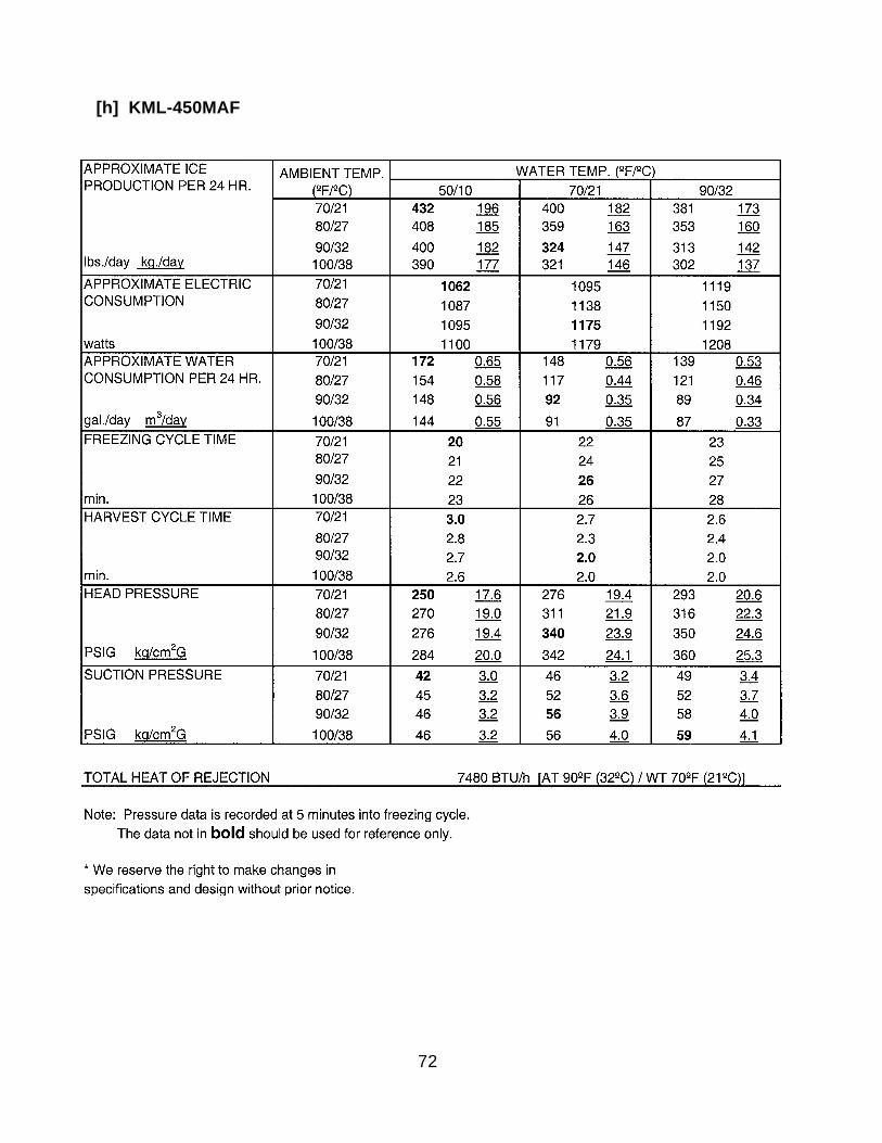
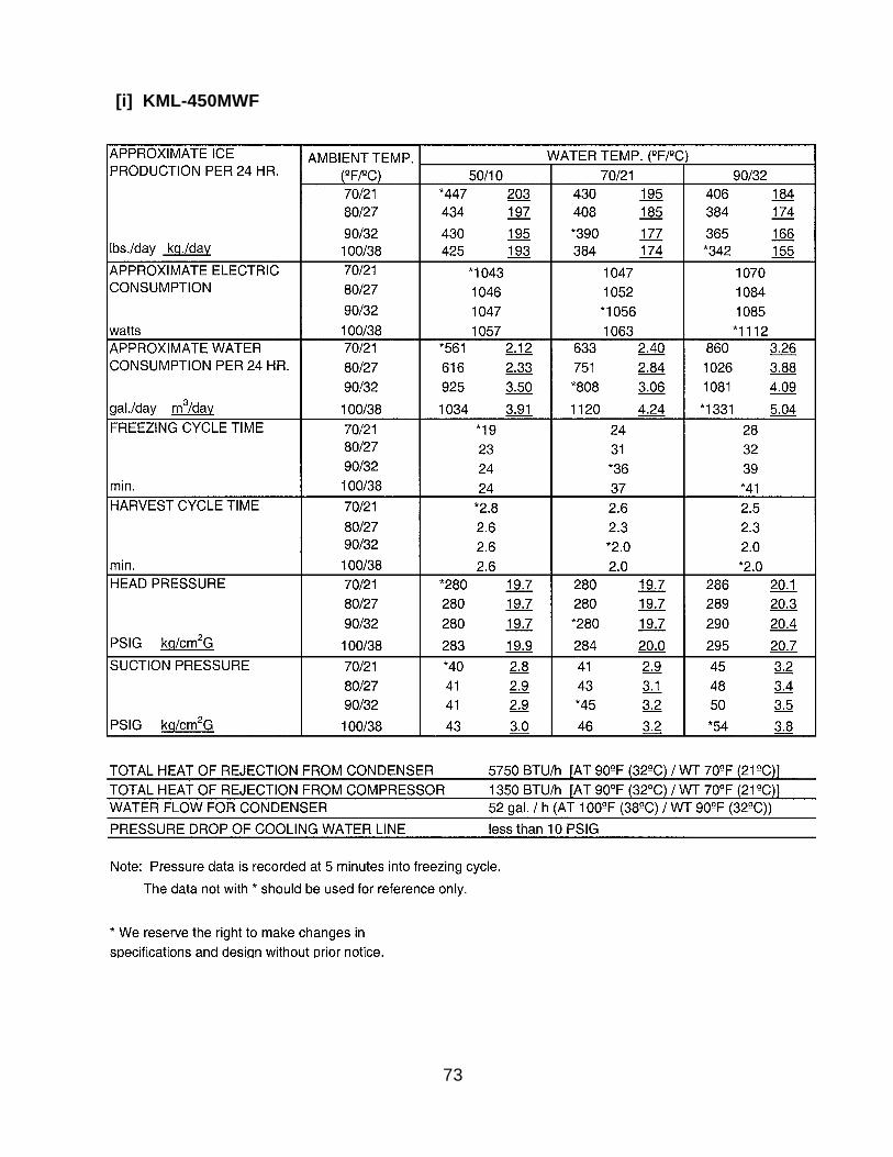
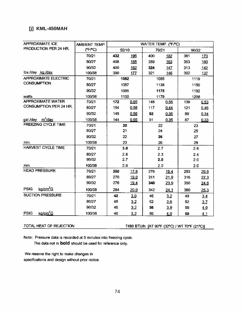
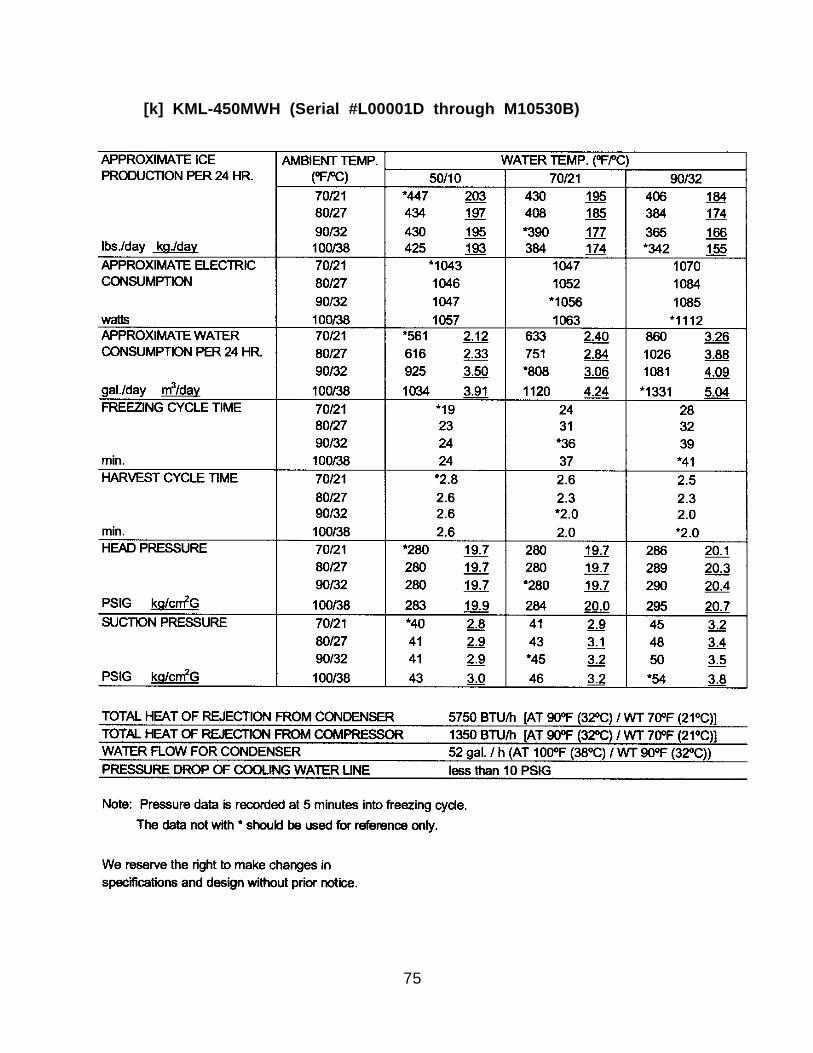
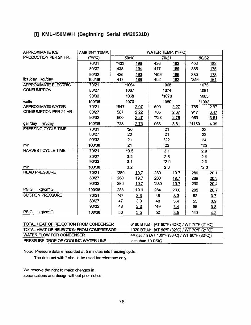
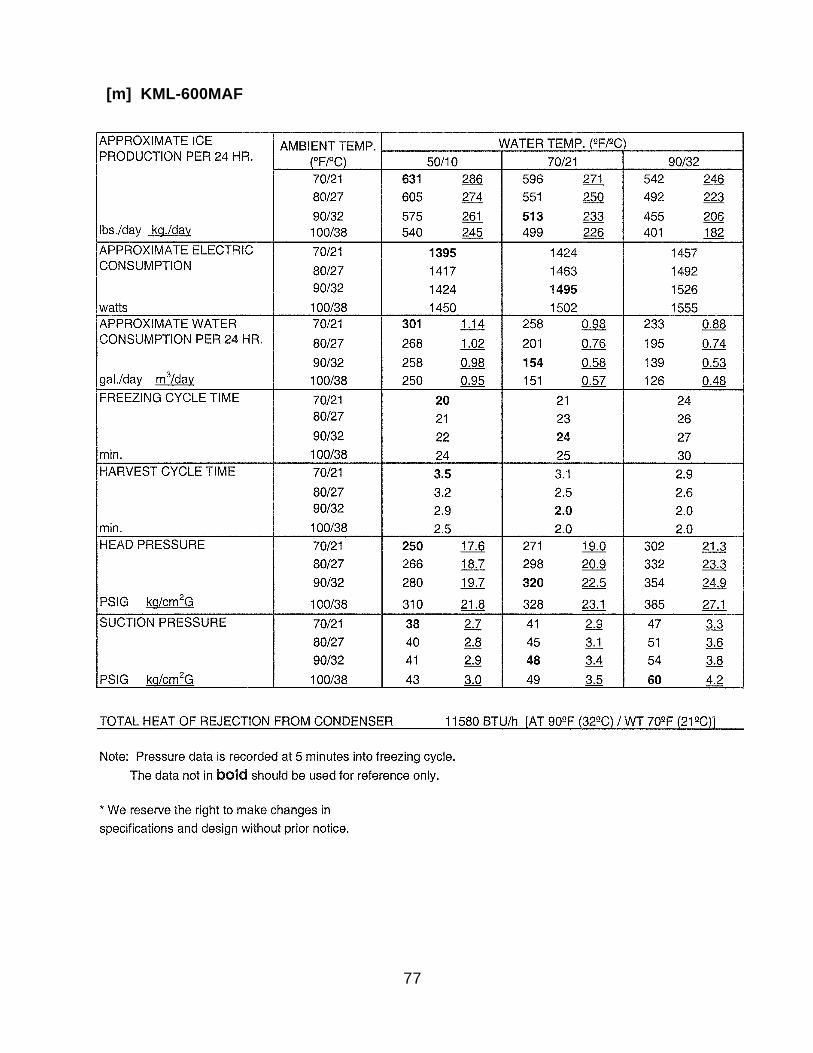
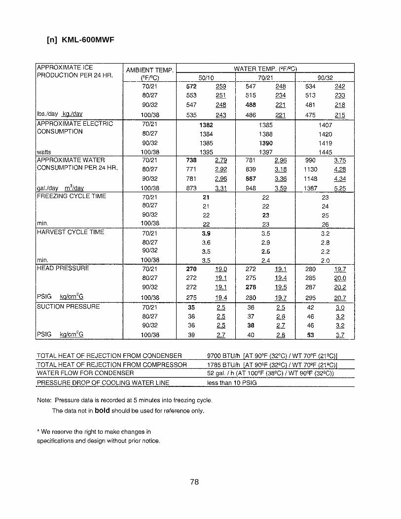
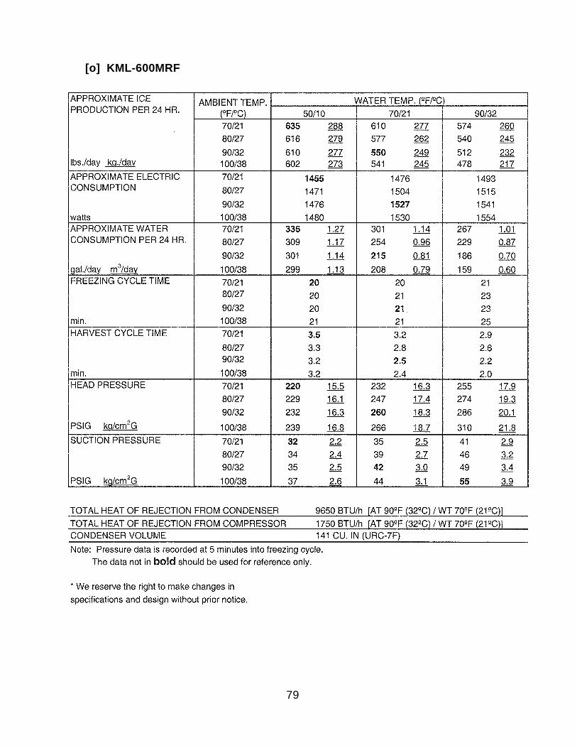
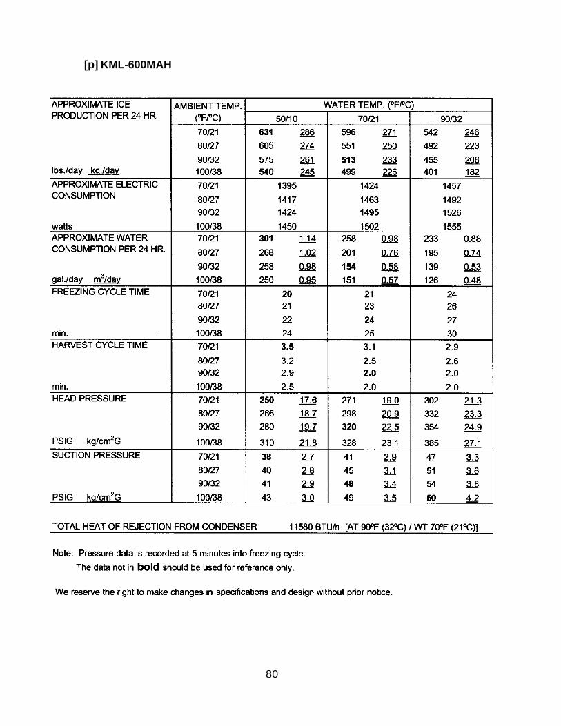
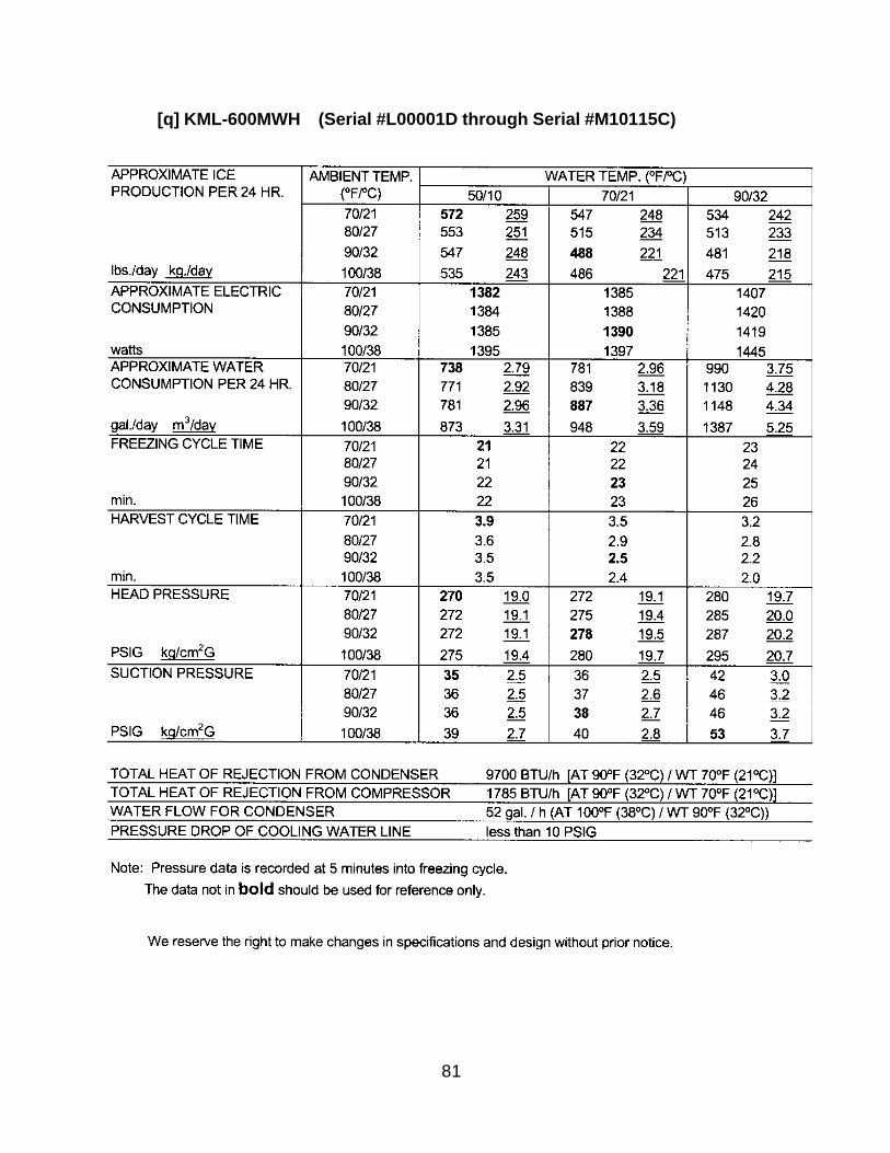
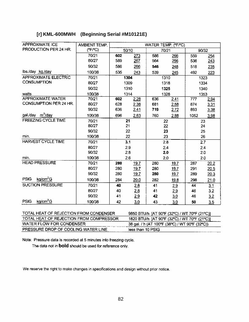
[h] KML-450MAF .....................................................................................................................72[i] KML-450MWF ...................................................................................................................73[j] KML-450MAH ....................................................................................................................74[k] KML-450MWH (Serial #L00001D through M10530B) .......................................................75[l] KML-450MWH (Beginning Serial #M20531D) ...................................................................76[m] KML-600MAF ....................................................................................................................77[n] KML-600MWF ...................................................................................................................78[o] KML-600MRF .....................................................................................................................79[p] KML-600MAH .....................................................................................................................80[q] KML-600MWH (Serial #L00001D through M10115C) ........................................................81[ r ] KML-600MWH (Beginning Serial #M10121E)....................................................................82[s] KML-600MRH ....................................................................................................................83
IV. SERVICE DIAGNOSIS ................................................................................................................841. NO ICE PRODUCTION ...........................................................................................................842. EVAPORATOR IS FROZEN UP ..............................................................................................873. LOW ICE PRODUCTION ........................................................................................................874. ABNORMAL ICE ......................................................................................................................885. OTHERS .................................................................................................................................89
V. REMOVAL AND REPLACEMENT OF COMPONENTS ...............................................................891. SERVICE FOR REFRIGERANT LINES ..................................................................................89
[a] REFRIGERANT RECOVERY ...........................................................................................89[b] EVACUATION AND RECHARGE [R-404A] .......................................................................89
2. BRAZING .................................................................................................................................903. REMOVAL AND REPLACEMENT OF COMPRESSOR .........................................................914. REMOVAL AND REPLACEMENT OF DRIER .........................................................................925. REMOVAL AND REPLACEMENT OF EXPANSION VALVE ....................................................936. REMOVAL AND REPLACEMENT OF HOT GAS VALVE AND.................................................... LINE VALVE ............................................................................................................................947. REMOVAL AND REPLACEMENT OF EVAPORATOR ...........................................................968. REMOVAL AND REPLACEMENT OF WATER-REGULATING VALVE .................................... - WATER COOLED MODEL ONLY ......................................................................................979. ADJUSTMENT OF WATER-REGULATING VALVE .................................................................. - WATER COOLED MODEL ONLY ......................................................................................98
10. REMOVAL AND REPLACEMENT OF CONDENSING PRESSURE ......................................... REGULATOR (C.P.R.) - REMOTE AIR-COOLED MODEL ONLY ........................................9911. REMOVAL AND REPLACEMENT OF THERMISTOR ...........................................................10012. REMOVAL AND REPLACEMENT OF FAN MOTOR..............................................................10113. REMOVAL AND REPLACEMENT OF WATER VALVE..........................................................10214. REMOVAL AND REPLACEMENT OF PUMP MOTOR ..........................................................10315. REMOVAL AND REPLACEMENT OF SPRAY TUBES ..........................................................103
VI. CLEANING AND MAINTENANCE INSTRUCTIONS...................................................................1041. PREPARING THE ICEMAKER FOR LONG STORAGE........................................................ 1042. CLEANING PROCEDURE ....................................................................................................1063. SANITIZING PROCEDURE ................................................................................................... 1084. MAINTENANCE......................................................................................................................109
6
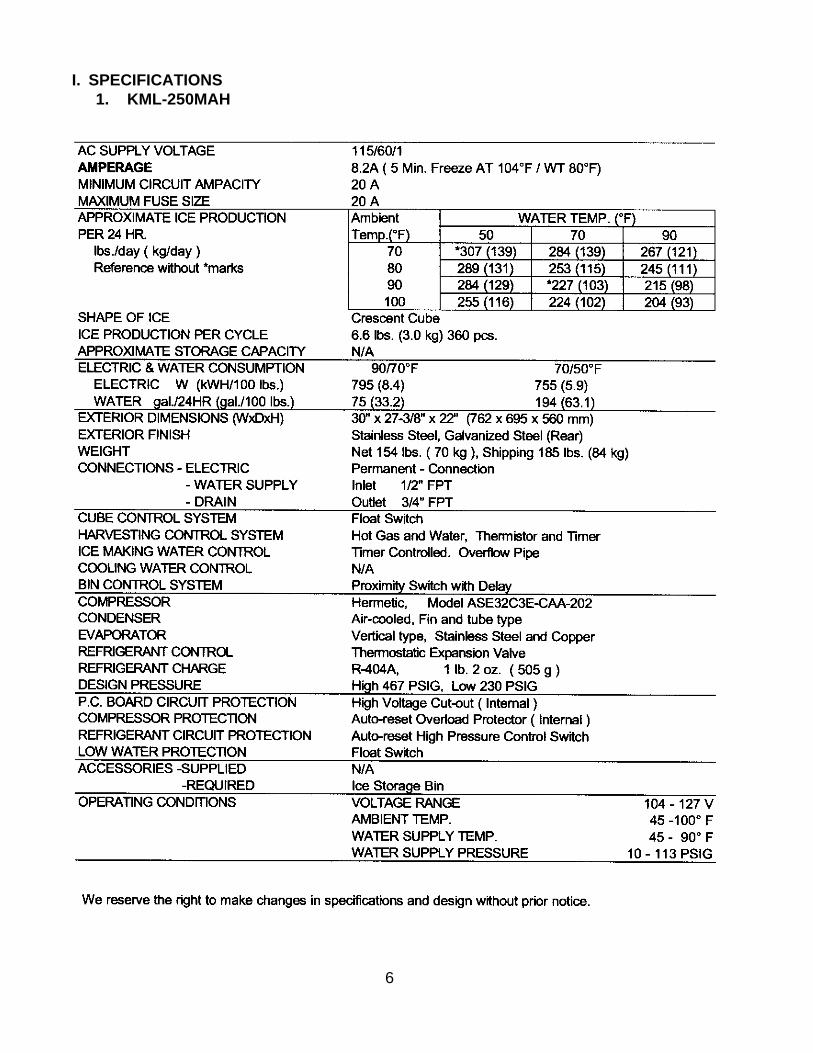
I. SPECIFICATIONS1. KML-250MAH
7
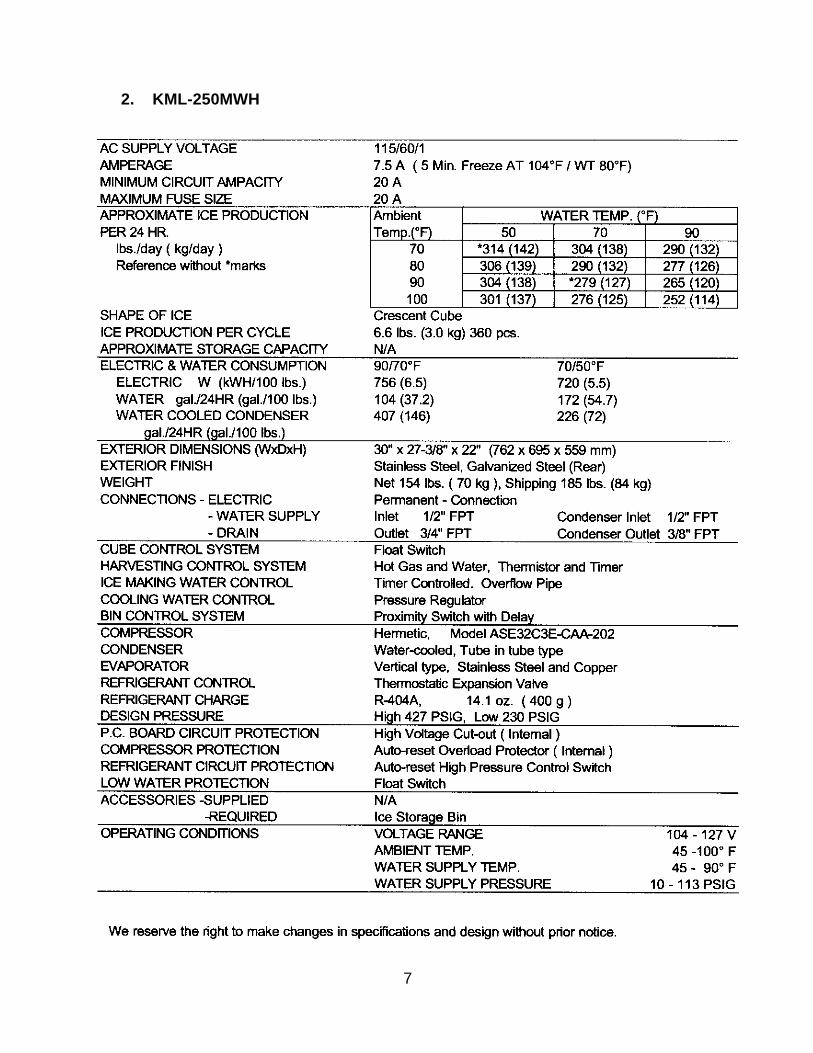
2. KML-250MWH
8
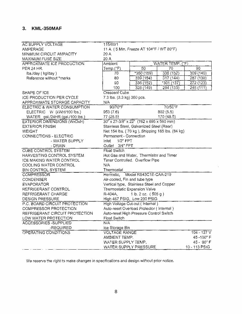
3. KML-350MAF
9
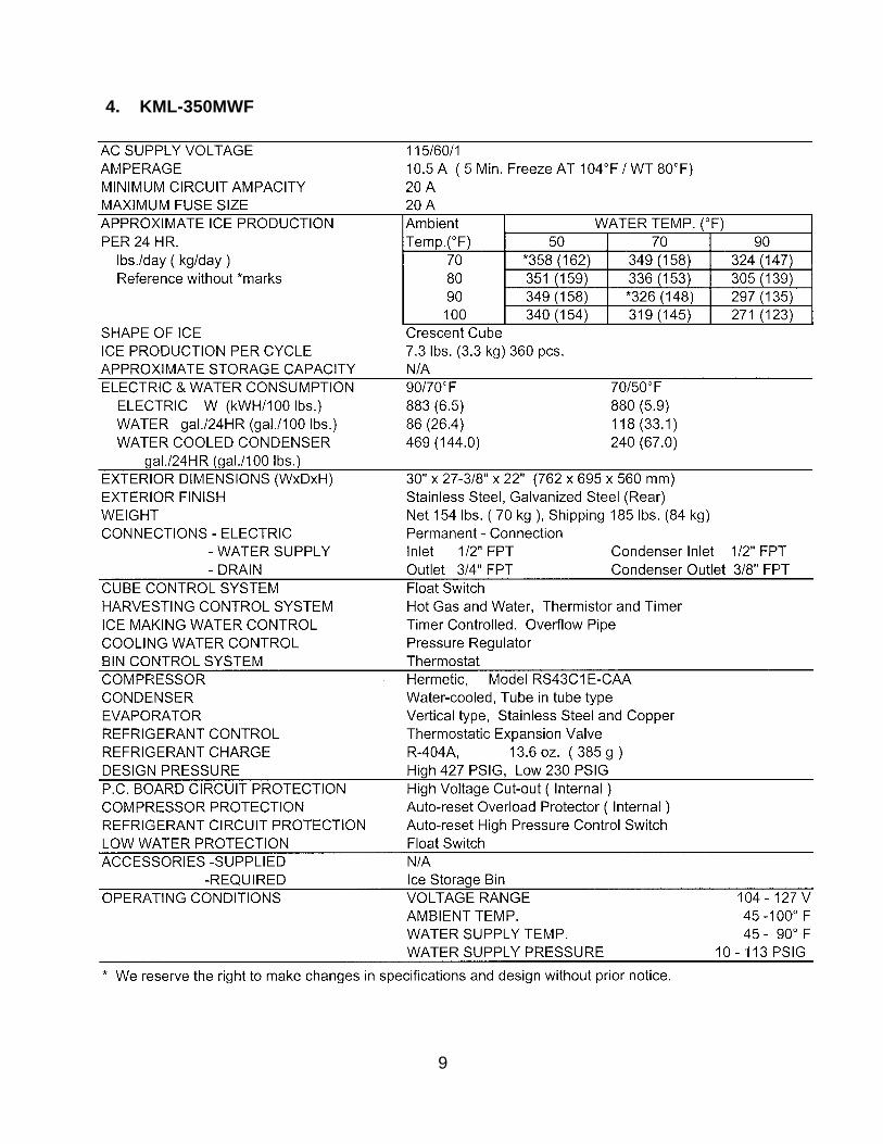
4. KML-350MWF
10
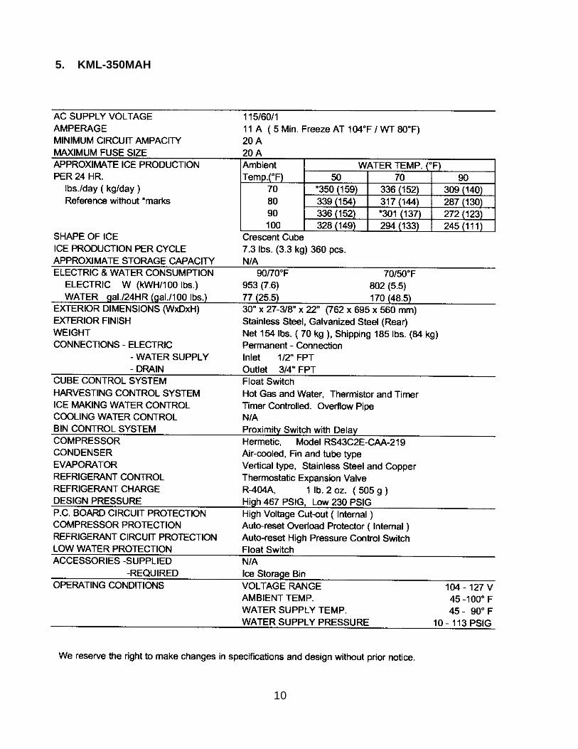
5. KML-350MAH
11
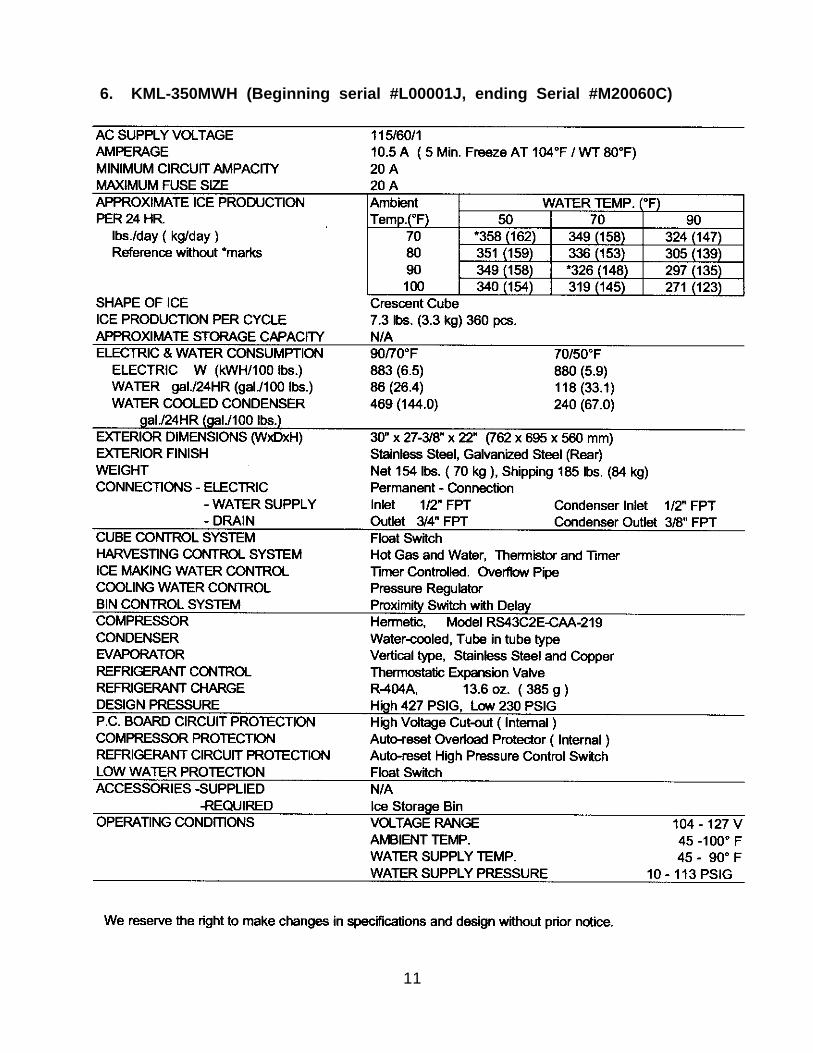
6. KML-350MWH (Beginning serial #L00001J, ending Serial #M20060C)
12
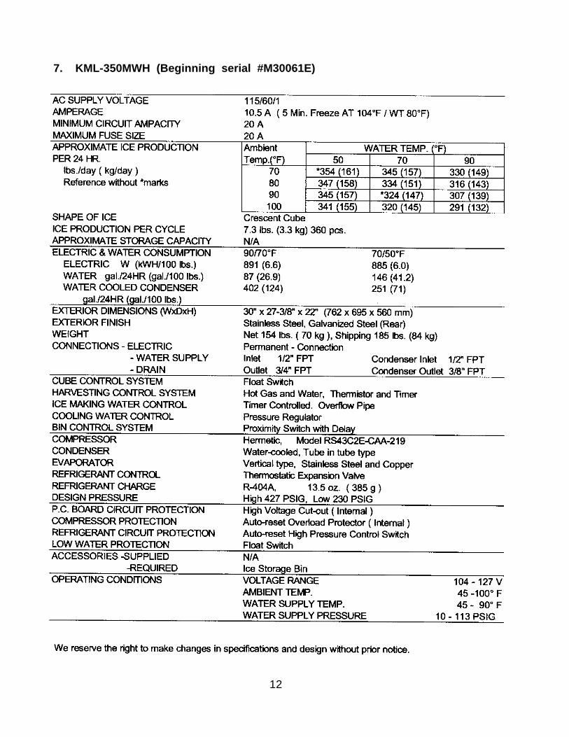
7. KML-350MWH (Beginning serial #M30061E)
13
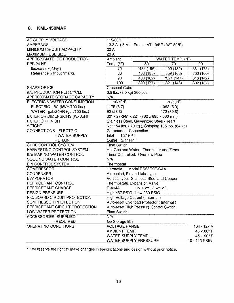
8. KML-450MAF
14
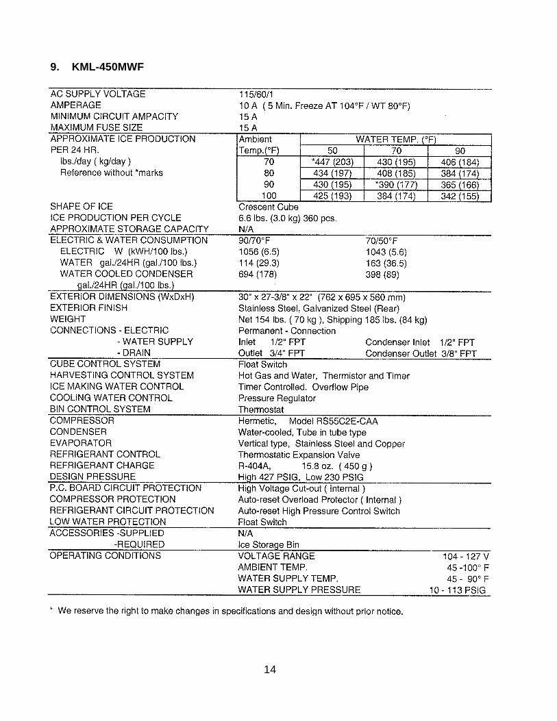
9. KML-450MWF
15
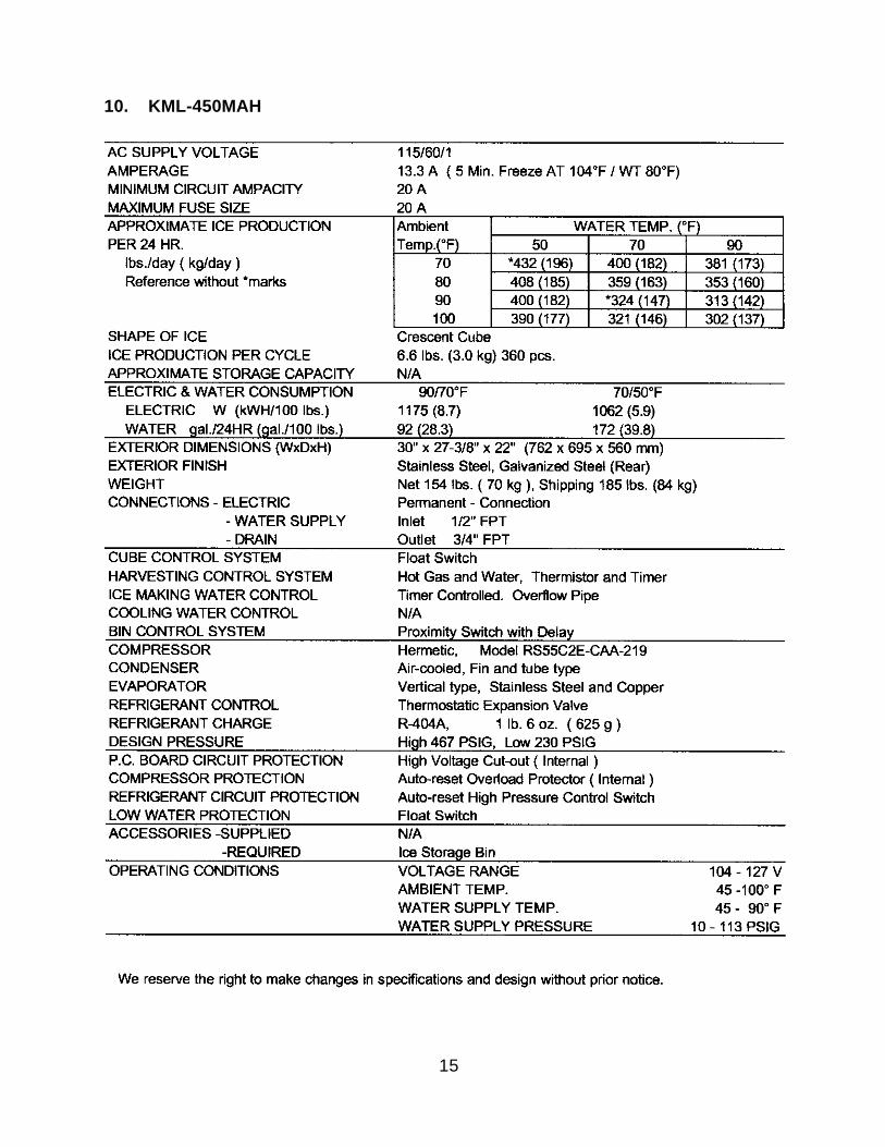
10. KML-450MAH
16
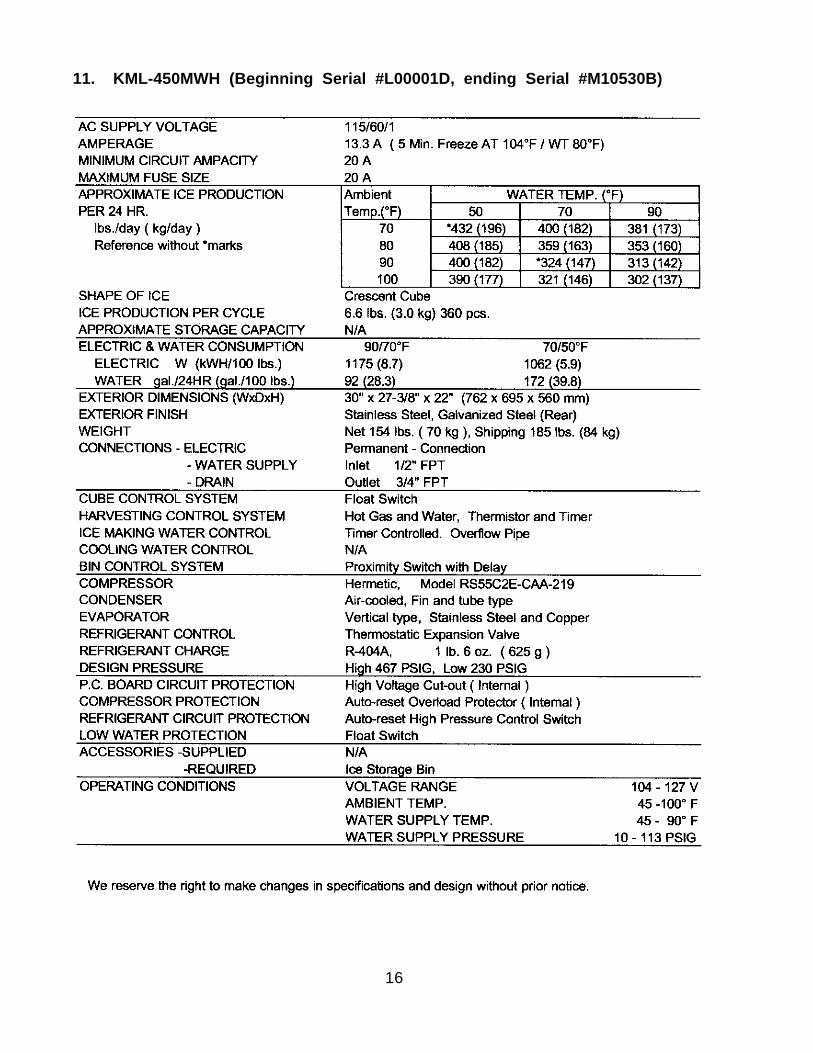
11. KML-450MWH (Beginning Serial #L00001D, ending Serial #M10530B)
17
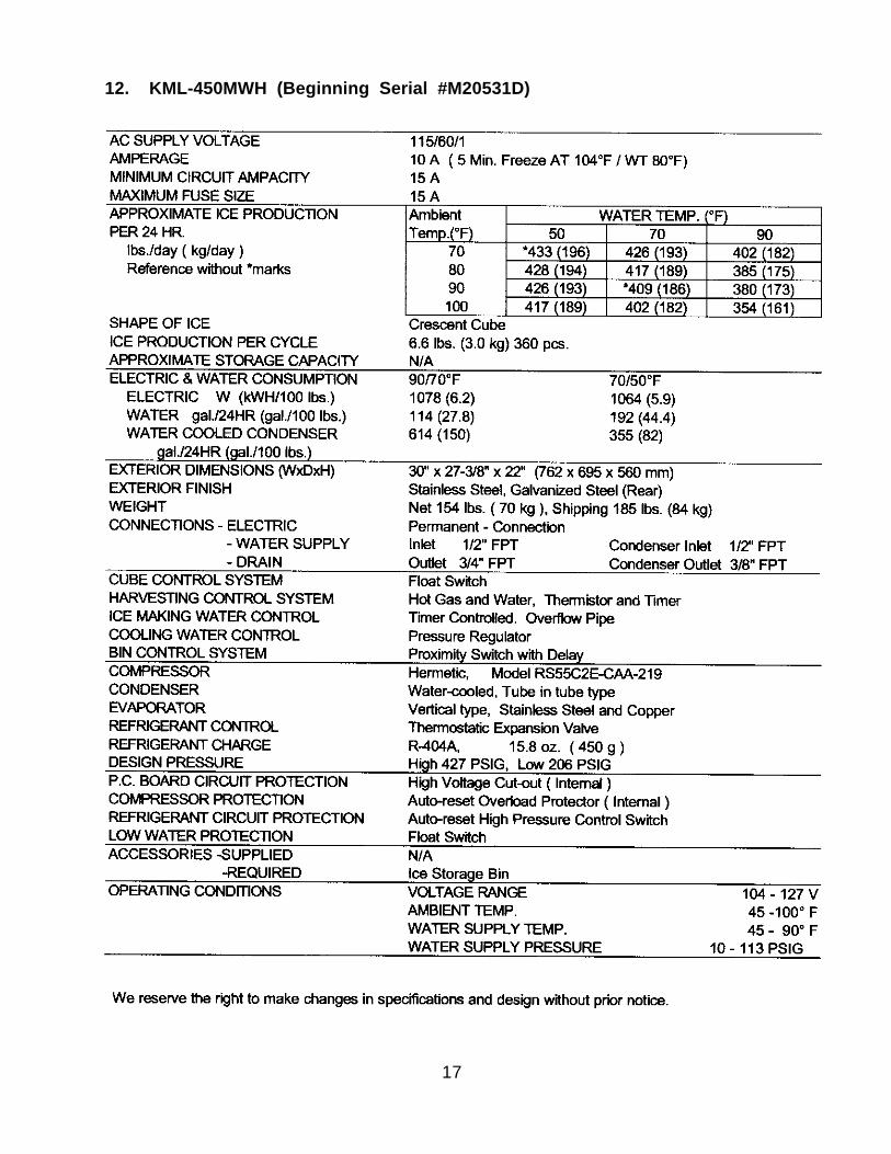
12. KML-450MWH (Beginning Serial #M20531D)
18
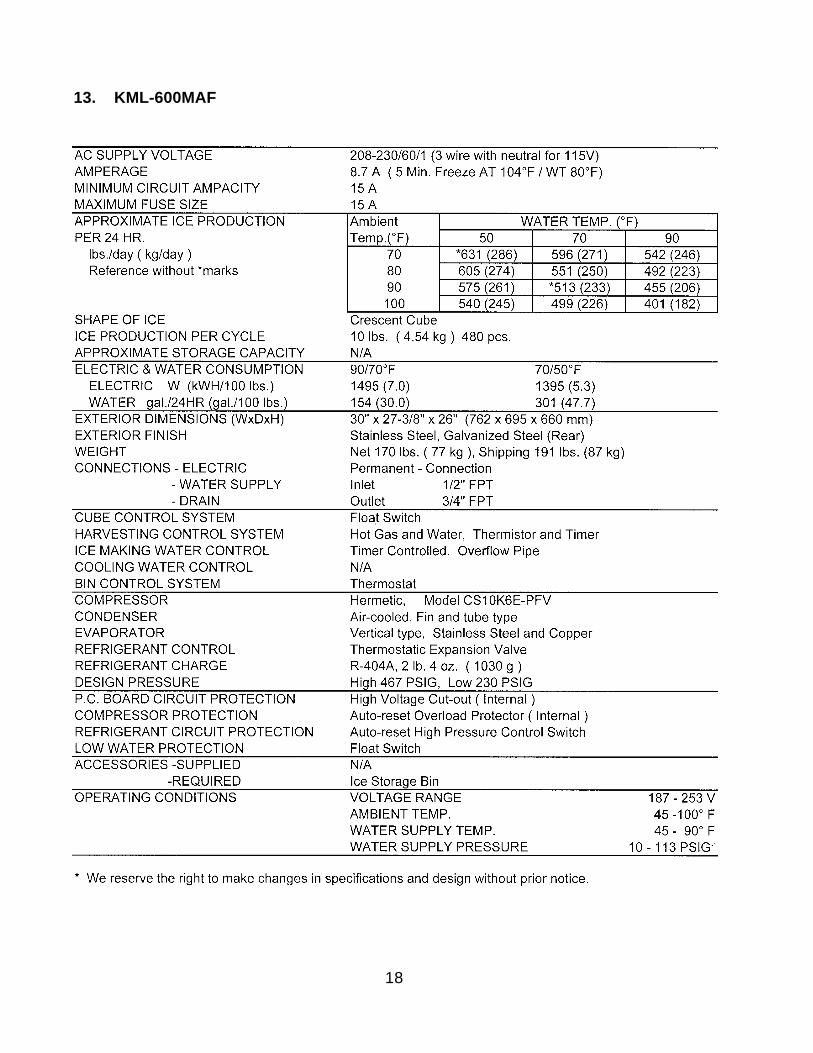
13. KML-600MAF
19
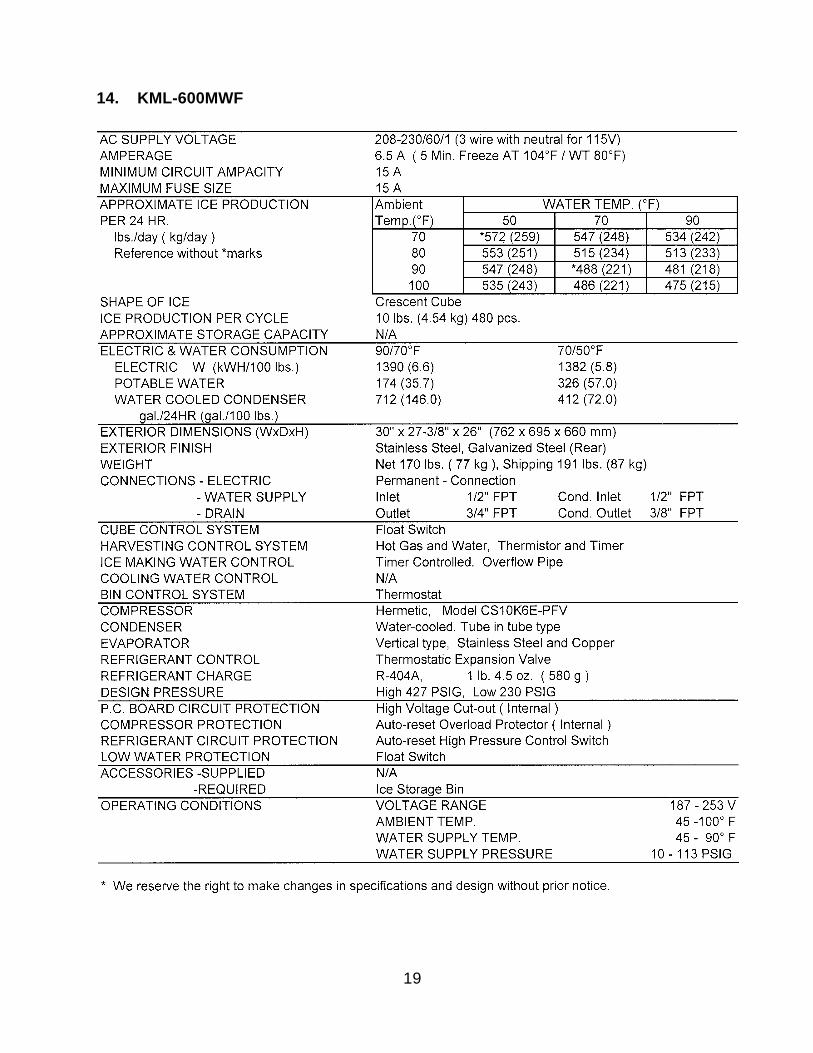
14. KML-600MWF
20
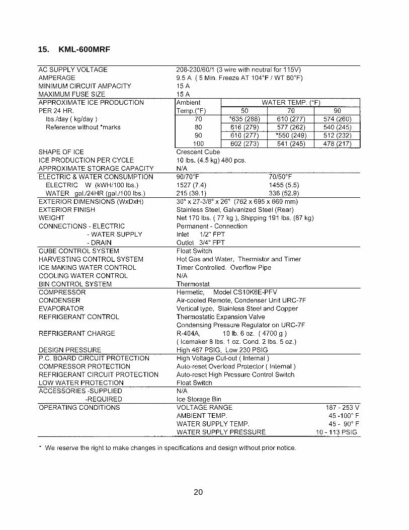
15. KML-600MRF
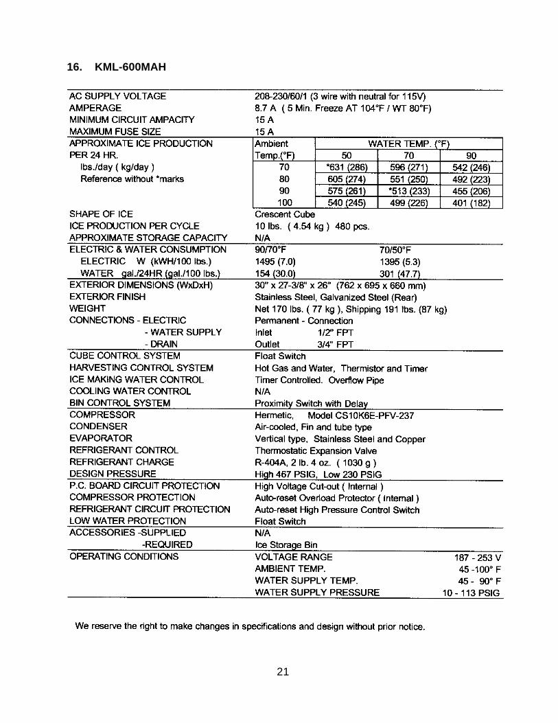
21
16. KML-600MAH
22
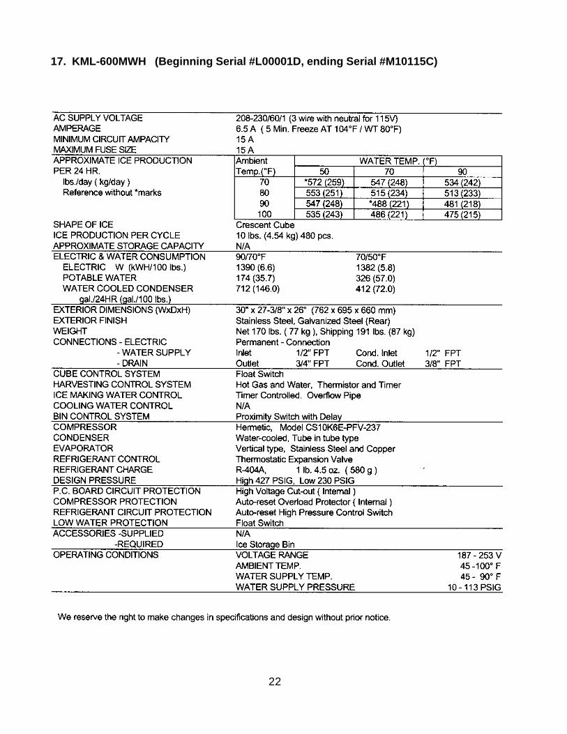
17. KML-600MWH (Beginning Serial #L00001D, ending Serial #M10115C)
23
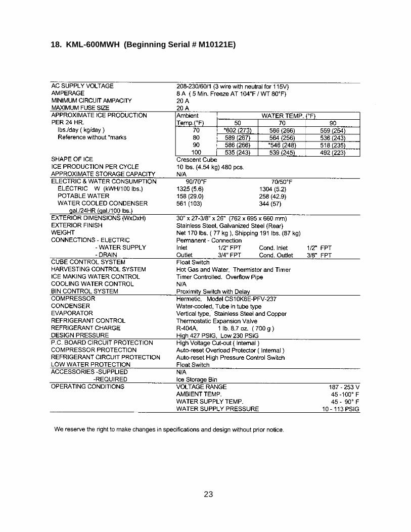
18. KML-600MWH (Beginning Serial # M10121E)
24
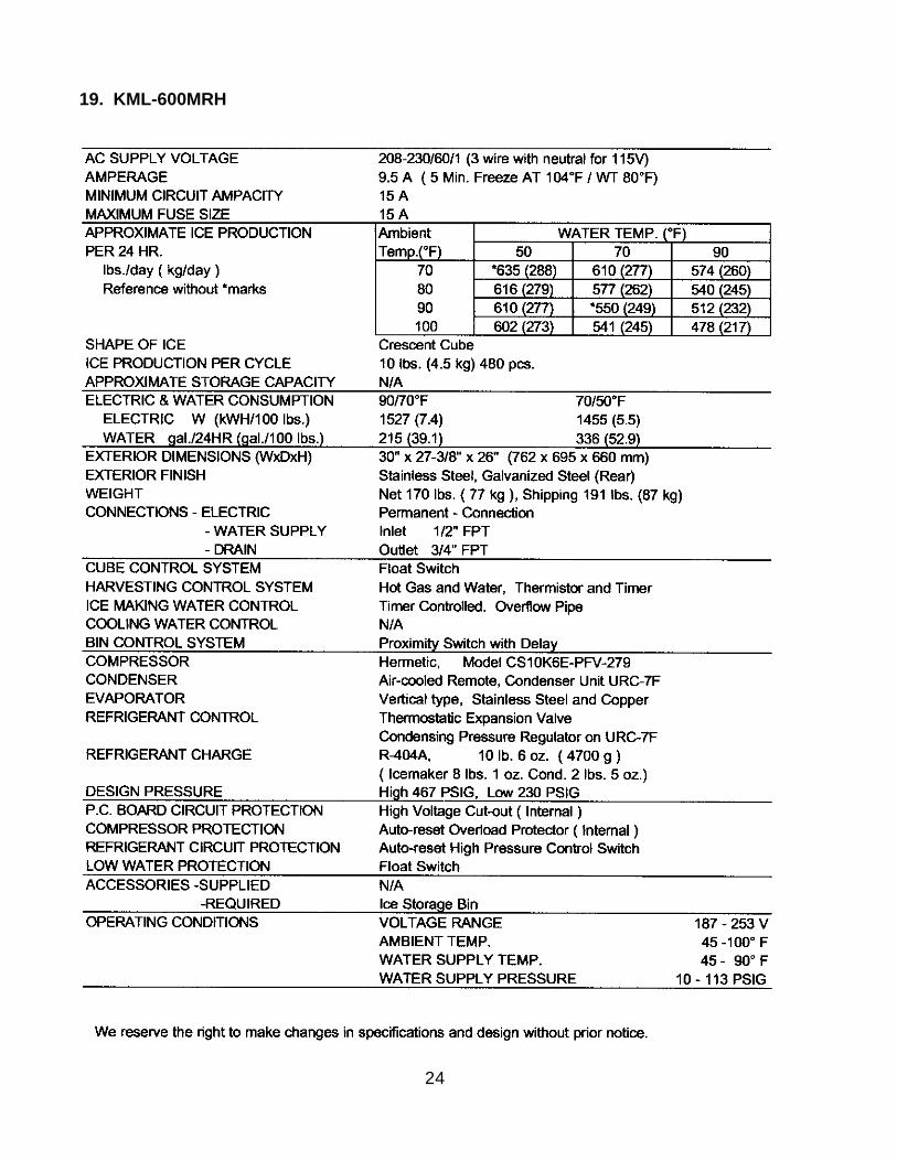
19. KML-600MRH
25
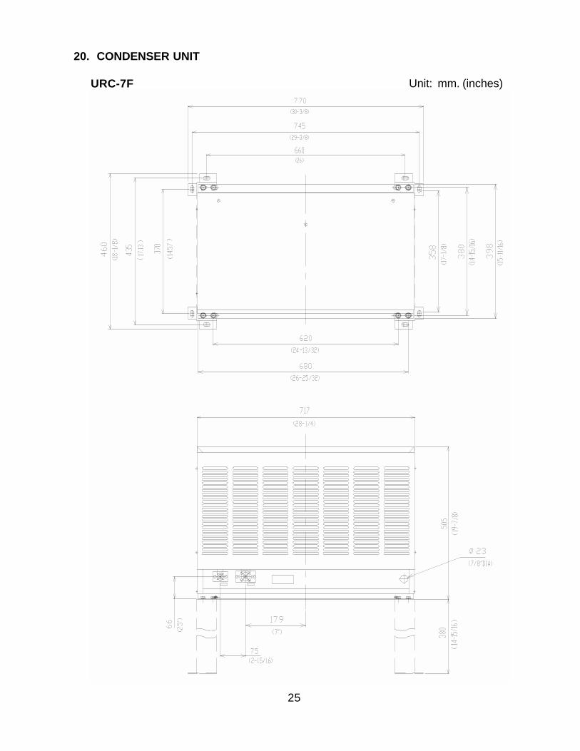
20. CONDENSER UNIT
URC-7F Unit: mm. (inches)
26
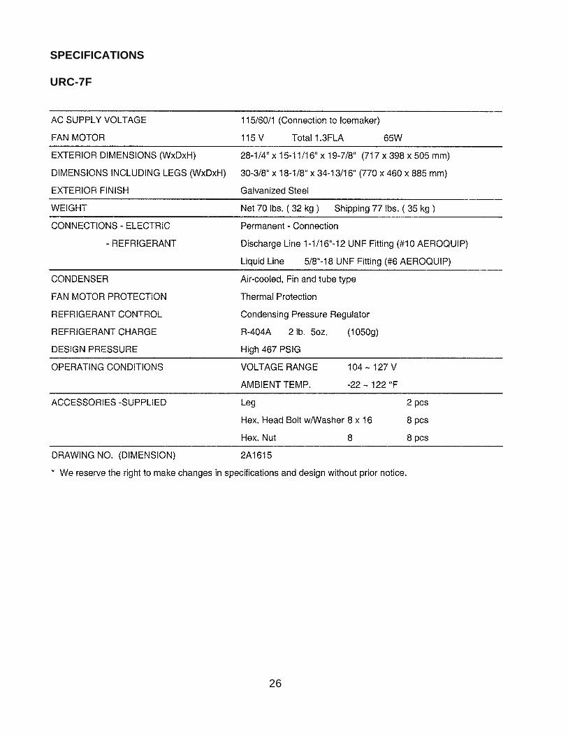
SPECIFICATIONS
URC-7F
27
II. GENERAL INFORMATION
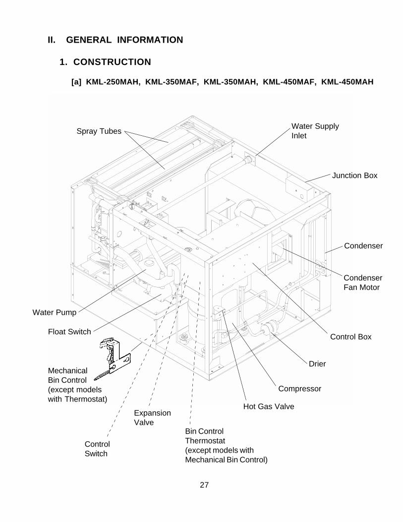
1. CONSTRUCTION
[a] KML-250MAH, KML-350MAF, KML-350MAH, KML-450MAF, KML-450MAH
Spray Tubes Water SupplyInlet
Junction Box
Condenser
CondenserFan Motor
Control Box
Drier
Hot Gas Valve
Compressor
Float Switch
Water Pump
Bin ControlThermostat(except models withMechanical Bin Control)
ControlSwitch
ExpansionValve
MechanicalBin Control(except modelswith Thermostat)
28
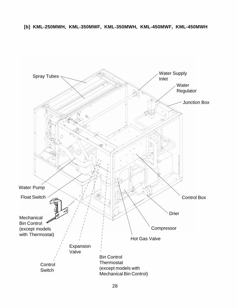
[b] KML-250MWH, KML-350MWF, KML-350MWH, KML-450MWF, KML-450MWH
Spray Tubes Water SupplyInlet
Junction Box
Control Box
Drier
Hot Gas Valve
Compressor
WaterRegulator
Float Switch
Water Pump
Bin ControlThermostat(except models withMechanical Bin Control)
ControlSwitch
ExpansionValve
MechanicalBin Control(except modelswith Thermostat)
29
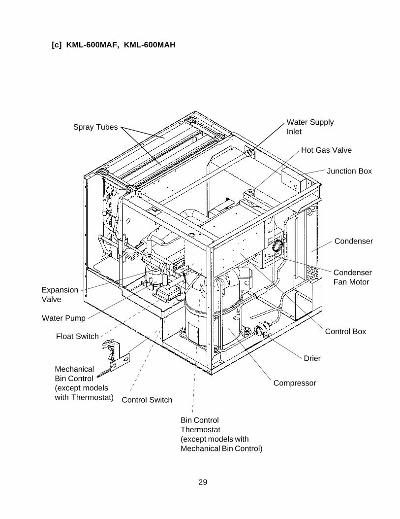
Spray Tubes Water SupplyInlet
Junction Box
Condenser
CondenserFan Motor
Control Box
Drier
Hot Gas Valve
Compressor
Float Switch
Control Switch
Water Pump
ExpansionValve
[c] KML-600MAF, KML-600MAH
Bin ControlThermostat(except models withMechanical Bin Control)
MechanicalBin Control(except modelswith Thermostat)
30
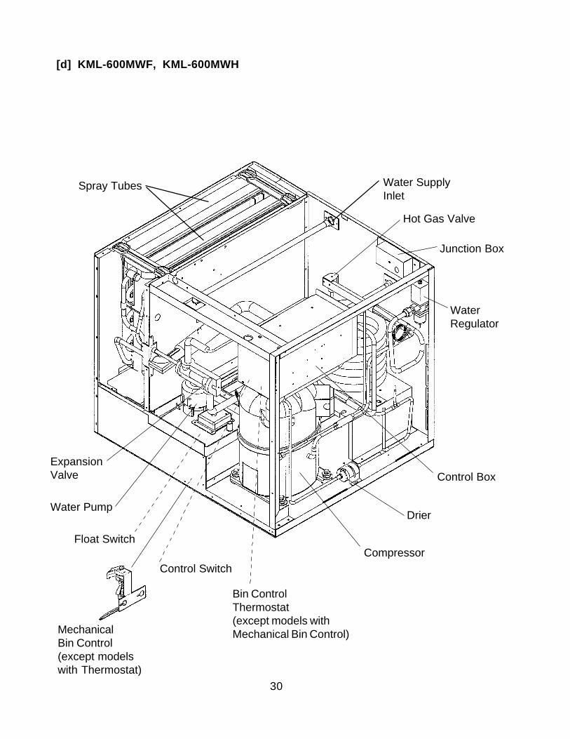
[d] KML-600MWF, KML-600MWH
Spray Tubes
Junction Box
WaterRegulator
Control Box
Drier
Hot Gas Valve
Float Switch
Control Switch
Water Pump
ExpansionValve
Compressor
Water SupplyInlet
Bin ControlThermostat(except models withMechanical Bin Control)Mechanical
Bin Control(except modelswith Thermostat)
31
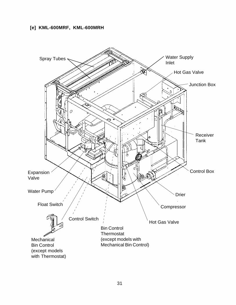
[e] KML-600MRF, KML-600MRH
Spray Tubes
Junction Box
ReceiverTank
Control Box
Drier
Hot Gas Valve
Float Switch
Control Switch
Water Pump
ExpansionValve
Compressor
Water SupplyInlet
Hot Gas ValveBin ControlThermostat(except models withMechanical Bin Control)
MechanicalBin Control(except modelswith Thermostat)
32
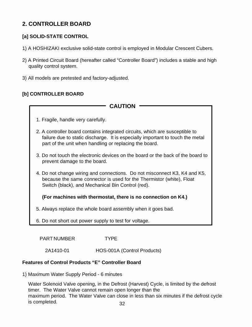
2. CONTROLLER BOARD
[a] SOLID-STATE CONTROL
1) A HOSHIZAKI exclusive solid-state control is employed in Modular Crescent Cubers.
2) A Printed Circuit Board (hereafter called “Controller Board”) includes a stable and highquality control system.
3) All models are pretested and factory-adjusted.
[b] CONTROLLER BOARD
CAUTION
1. Fragile, handle very carefully.
2. A controller board contains integrated circuits, which are susceptible tofailure due to static discharge. It is especially important to touch the metalpart of the unit when handling or replacing the board.
3. Do not touch the electronic devices on the board or the back of the board toprevent damage to the board.
4. Do not change wiring and connections. Do not misconnect K3, K4 and K5,because the same connector is used for the Thermistor (white), FloatSwitch (black), and Mechanical Bin Control (red).
(For machines with thermostat, there is no connection on K4.)
5. Always replace the whole board assembly when it goes bad.
6. Do not short out power supply to test for voltage.
PART NUMBER TYPE
2A1410-01 HOS-001A (Control Products)
Features of Control Products “E” Controller Board
1) Maximum Water Supply Period - 6 minutes
Water Solenoid Valve opening, in the Defrost (Harvest) Cycle, is limited by the defrosttimer. The Water Valve cannot remain open longer than themaximum period. The Water Valve can close in less than six minutes if the defrost cycleis completed.
33
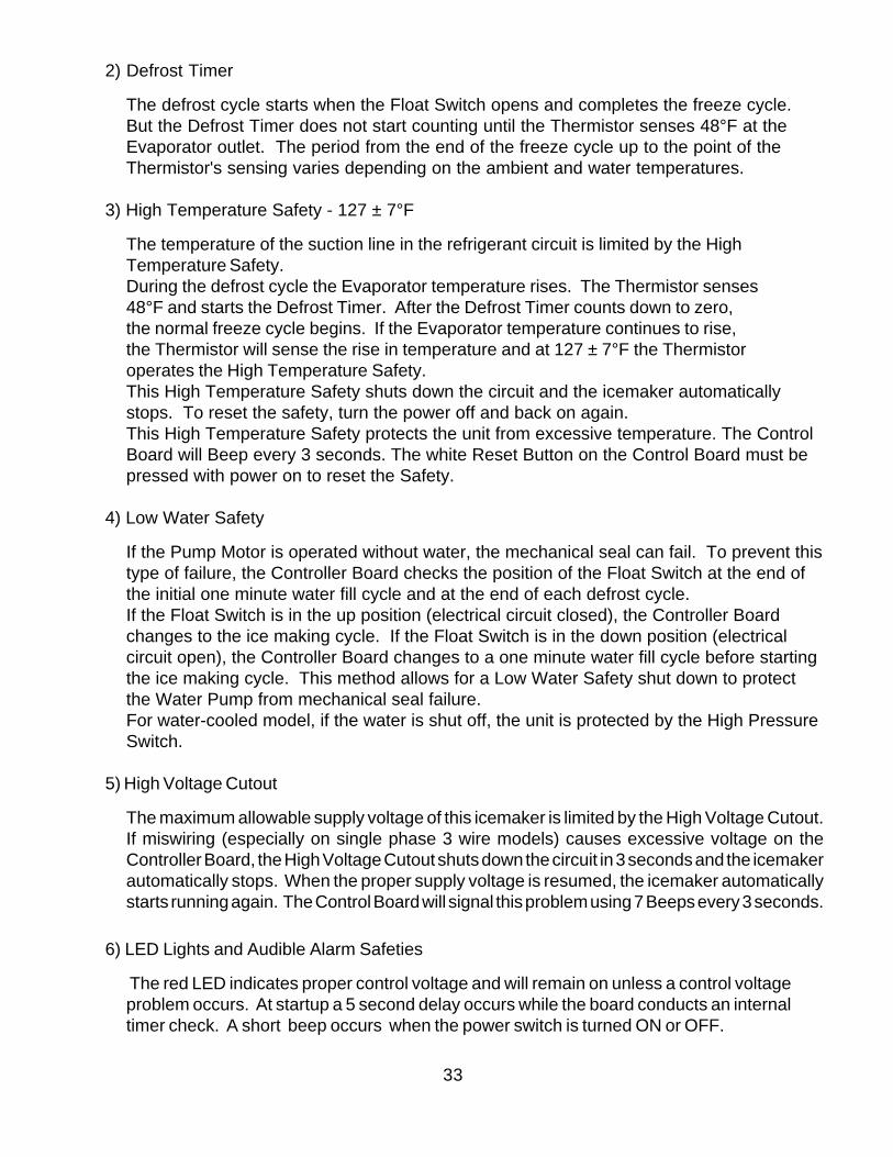
2) Defrost Timer
The defrost cycle starts when the Float Switch opens and completes the freeze cycle.But the Defrost Timer does not start counting until the Thermistor senses 48°F at theEvaporator outlet. The period from the end of the freeze cycle up to the point of theThermistor's sensing varies depending on the ambient and water temperatures.
3) High Temperature Safety - 127 ± 7°F
The temperature of the suction line in the refrigerant circuit is limited by the HighTemperature Safety.During the defrost cycle the Evaporator temperature rises. The Thermistor senses48°F and starts the Defrost Timer. After the Defrost Timer counts down to zero,the normal freeze cycle begins. If the Evaporator temperature continues to rise,the Thermistor will sense the rise in temperature and at 127 ± 7°F the Thermistoroperates the High Temperature Safety.This High Temperature Safety shuts down the circuit and the icemaker automaticallystops. To reset the safety, turn the power off and back on again.This High Temperature Safety protects the unit from excessive temperature. The ControlBoard will Beep every 3 seconds. The white Reset Button on the Control Board must bepressed with power on to reset the Safety.
4) Low Water Safety
If the Pump Motor is operated without water, the mechanical seal can fail. To prevent thistype of failure, the Controller Board checks the position of the Float Switch at the end ofthe initial one minute water fill cycle and at the end of each defrost cycle.If the Float Switch is in the up position (electrical circuit closed), the Controller Boardchanges to the ice making cycle. If the Float Switch is in the down position (electricalcircuit open), the Controller Board changes to a one minute water fill cycle before startingthe ice making cycle. This method allows for a Low Water Safety shut down to protectthe Water Pump from mechanical seal failure.For water-cooled model, if the water is shut off, the unit is protected by the High PressureSwitch.
5) High Voltage Cutout
The maximum allowable supply voltage of this icemaker is limited by the High Voltage Cutout.If miswiring (especially on single phase 3 wire models) causes excessive voltage on theController Board, the High Voltage Cutout shuts down the circuit in 3 seconds and the icemakerautomatically stops. When the proper supply voltage is resumed, the icemaker automaticallystarts running again. The Control Board will signal this problem using 7 Beeps every 3 seconds.
6) LED Lights and Audible Alarm Safeties
The red LED indicates proper control voltage and will remain on unless a control voltageproblem occurs. At startup a 5 second delay occurs while the board conducts an internaltimer check. A short beep occurs when the power switch is turned ON or OFF.
34
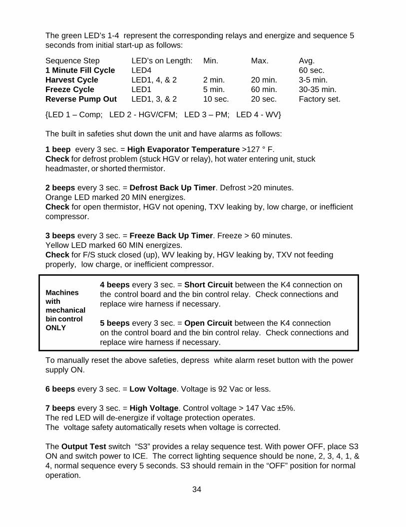
The green LED’s 1-4 represent the corresponding relays and energize and sequence 5seconds from initial start-up as follows:
Sequence Step LED’s on Length: Min. Max. Avg.1 Minute Fill Cycle LED4 60 sec.Harvest Cycle LED1, 4, & 2 2 min. 20 min. 3-5 min.Freeze Cycle LED1 5 min. 60 min. 30-35 min.Reverse Pump Out LED1, 3, & 2 10 sec. 20 sec. Factory set.
LED 1 – Comp; LED 2 - HGV/CFM; LED 3 – PM; LED 4 - WV
The built in safeties shut down the unit and have alarms as follows:
1 beep every 3 sec. = High Evaporator Temperature >127 ° F.Check for defrost problem (stuck HGV or relay), hot water entering unit, stuckheadmaster, or shorted thermistor.
2 beeps every 3 sec. = Defrost Back Up Timer. Defrost >20 minutes.Orange LED marked 20 MIN energizes.Check for open thermistor, HGV not opening, TXV leaking by, low charge, or inefficientcompressor.
3 beeps every 3 sec. = Freeze Back Up Timer. Freeze > 60 minutes.Yellow LED marked 60 MIN energizes.Check for F/S stuck closed (up), WV leaking by, HGV leaking by, TXV not feedingproperly, low charge, or inefficient compressor.
To manually reset the above safeties, depress white alarm reset button with the powersupply ON.
6 beeps every 3 sec. = Low Voltage. Voltage is 92 Vac or less.
7 beeps every 3 sec. = High Voltage. Control voltage > 147 Vac ±5%.The red LED will de-energize if voltage protection operates.The voltage safety automatically resets when voltage is corrected.
The Output Test switch “S3” provides a relay sequence test. With power OFF, place S3ON and switch power to ICE. The correct lighting sequence should be none, 2, 3, 4, 1, &4, normal sequence every 5 seconds. S3 should remain in the “OFF” position for normaloperation.
Machineswithmechanicalbin controlONLY
4 beeps every 3 sec. = Short Circuit between the K4 connection onthe control board and the bin control relay. Check connections andreplace wire harness if necessary.
5 beeps every 3 sec. = Open Circuit between the K4 connectionon the control board and the bin control relay. Check connections andreplace wire harness if necessary.
35
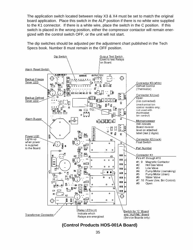
(Control Products HOS-001A Board)
The application switch located between relay X3 & X4 must be set to match the originalboard application. Place this switch in the ALP position if there is no white wire suppliedto the K1 connector. If there is a white wire, place the switch in the C position. If thisswitch is placed in the wrong position, either the compressor contactor will remain ener-gized with the control switch OFF, or the unit will not start.
The dip switches should be adjusted per the adjustment chart published in the TechSpecs book. Number 8 must remain in the OFF position.
36
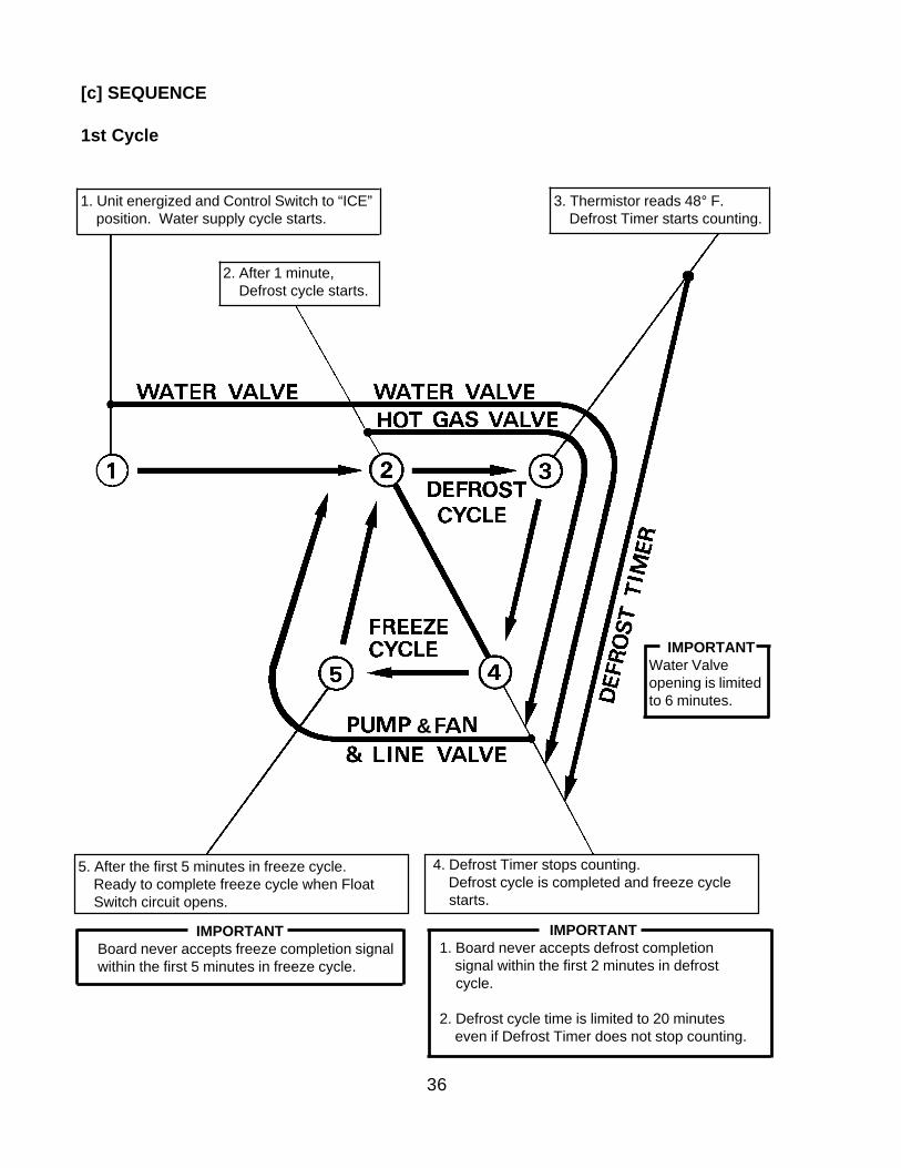
[c] SEQUENCE
1st Cycle
1. Unit energized and Control Switch to “ICE” position. Water supply cycle starts.
2. After 1 minute, Defrost cycle starts.
3. Thermistor reads 48° F. Defrost Timer starts counting.
IMPORTANTWater Valveopening is limitedto 6 minutes.
&
5. After the first 5 minutes in freeze cycle. Ready to complete freeze cycle when Float Switch circuit opens.
4. Defrost Timer stops counting. Defrost cycle is completed and freeze cycle starts.
IMPORTANTBoard never accepts freeze completion signalwithin the first 5 minutes in freeze cycle.
IMPORTANT1. Board never accepts defrost completion signal within the first 2 minutes in defrost cycle.
2. Defrost cycle time is limited to 20 minutes even if Defrost Timer does not stop counting.
37
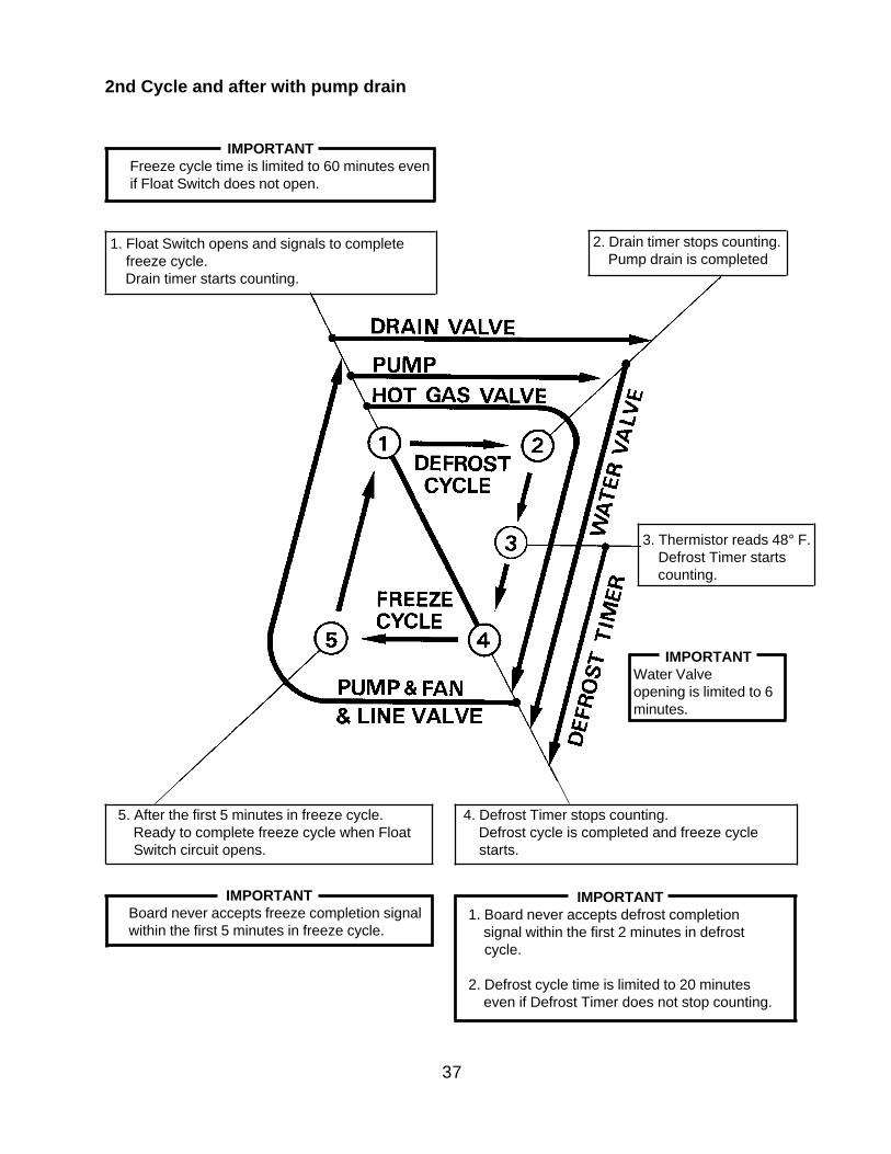
2nd Cycle and after with pump drain
IMPORTANTFreeze cycle time is limited to 60 minutes evenif Float Switch does not open.
1. Float Switch opens and signals to complete freeze cycle. Drain timer starts counting.
2. Drain timer stops counting. Pump drain is completed
3. Thermistor reads 48° F. Defrost Timer starts counting.
IMPORTANTWater Valveopening is limited to 6minutes.
5. After the first 5 minutes in freeze cycle. Ready to complete freeze cycle when Float Switch circuit opens.
4. Defrost Timer stops counting. Defrost cycle is completed and freeze cycle starts.
IMPORTANTBoard never accepts freeze completion signalwithin the first 5 minutes in freeze cycle.
IMPORTANT1. Board never accepts defrost completion signal within the first 2 minutes in defrost cycle.
2. Defrost cycle time is limited to 20 minutes even if Defrost Timer does not stop counting.
38
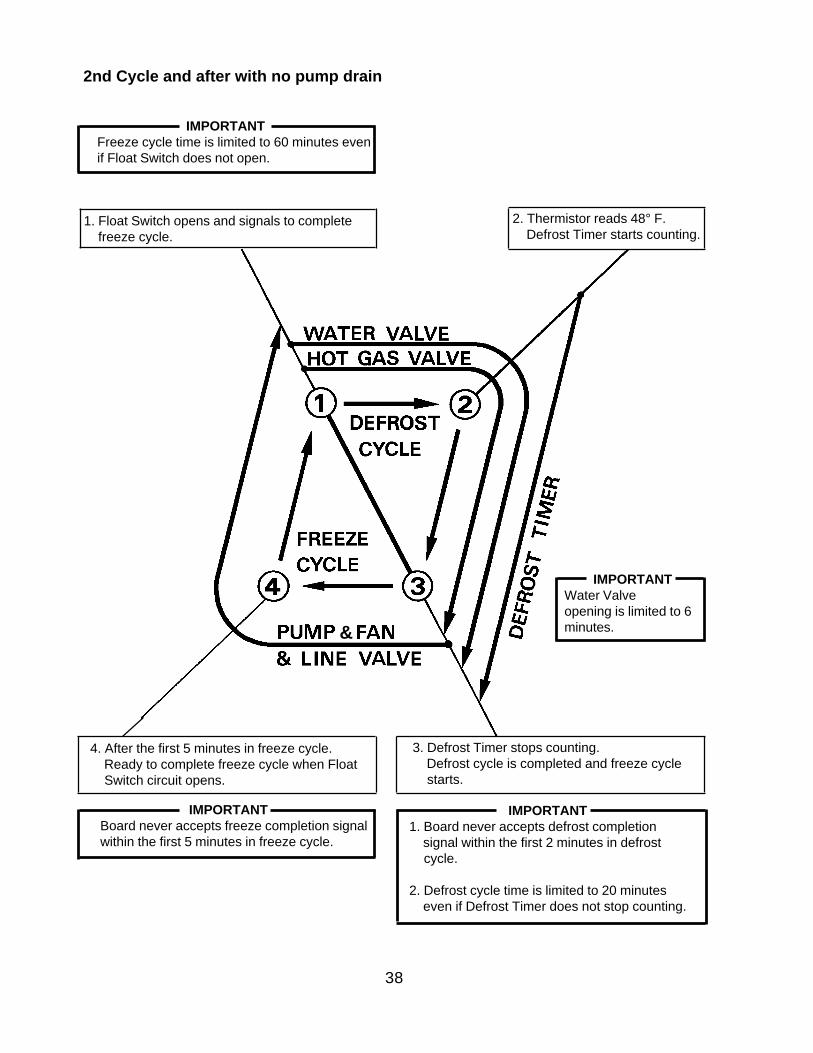
IMPORTANTFreeze cycle time is limited to 60 minutes evenif Float Switch does not open.
2nd Cycle and after with no pump drain
1. Float Switch opens and signals to complete freeze cycle.
2. Thermistor reads 48° F. Defrost Timer starts counting.
IMPORTANTWater Valveopening is limited to 6minutes.
4. After the first 5 minutes in freeze cycle. Ready to complete freeze cycle when Float Switch circuit opens.
3. Defrost Timer stops counting. Defrost cycle is completed and freeze cycle starts.
IMPORTANTBoard never accepts freeze completion signalwithin the first 5 minutes in freeze cycle.
IMPORTANT1. Board never accepts defrost completion signal within the first 2 minutes in defrost cycle.
2. Defrost cycle time is limited to 20 minutes even if Defrost Timer does not stop counting.
&
39
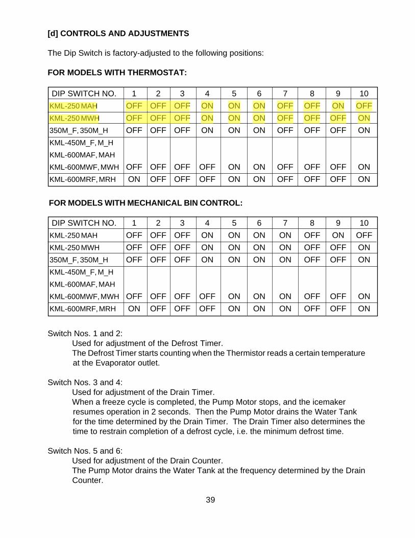
[d] CONTROLS AND ADJUSTMENTS
The Dip Switch is factory-adjusted to the following positions:
FOR MODELS WITH THERMOSTAT:
Switch Nos. 1 and 2:Used for adjustment of the Defrost Timer.The Defrost Timer starts counting when the Thermistor reads a certain temperature
at the Evaporator outlet.
Switch Nos. 3 and 4:Used for adjustment of the Drain Timer.When a freeze cycle is completed, the Pump Motor stops, and the icemaker
resumes operation in 2 seconds. Then the Pump Motor drains the Water Tank for the time determined by the Drain Timer. The Drain Timer also determines the time to restrain completion of a defrost cycle, i.e. the minimum defrost time.
Switch Nos. 5 and 6:Used for adjustment of the Drain Counter.The Pump Motor drains the Water Tank at the frequency determined by the Drain
Counter.
FOR MODELS WITH MECHANICAL BIN CONTROL:
DIP SWITCH NO. 1 2 3 4 5 6 7 8 9 10KML-250 MAH OFF OFF OFF ON ON ON OFF OFF ON OFFKML-250 MWH OFF OFF OFF ON ON ON OFF OFF OFF ON350M_F, 350M_H OFF OFF OFF ON ON ON OFF OFF OFF ONKML-450M_F, M_HKML-600MAF, MAHKML-600MWF, MWH OFF OFF OFF OFF ON ON OFF OFF OFF ONKML-600MRF, MRH ON OFF OFF OFF ON ON OFF OFF OFF ON
DIP SWITCH NO. 1 2 3 4 5 6 7 8 9 10KML-250 MAH OFF OFF OFF ON ON ON ON OFF ON OFFKML-250 MWH OFF OFF OFF ON ON ON ON OFF OFF ON350M_F, 350M_H OFF OFF OFF ON ON ON ON OFF OFF ONKML-450M_F, M_HKML-600MAF, MAHKML-600MWF, MWH OFF OFF OFF OFF ON ON ON OFF OFF ONKML-600MRF, MRH ON OFF OFF OFF ON ON ON OFF OFF ON
40
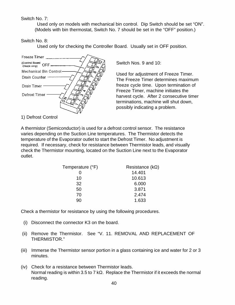
1) Defrost Control
A thermistor (Semiconductor) is used for a defrost control sensor. The resistancevaries depending on the Suction Line temperatures. The Thermistor detects thetemperature of the Evaporator outlet to start the Defrost Timer. No adjustment isrequired. If necessary, check for resistance between Thermistor leads, and visuallycheck the Thermistor mounting, located on the Suction Line next to the Evaporatoroutlet.
Temperature (°F) Resistance (kΩ) 0 14.40110 10.61332 6.00050 3.87170 2.47490 1.633
Check a thermistor for resistance by using the following procedures.
(i) Disconnect the connector K3 on the board.
(ii) Remove the Thermistor. See “V. 11. REMOVAL AND REPLACEMENT OFTHERMISTOR.”
(iii) Immerse the Thermistor sensor portion in a glass containing ice and water for 2 or 3minutes.
(iv) Check for a resistance between Thermistor leads.Normal reading is within 3.5 to 7 kΩ. Replace the Thermistor if it exceeds the normalreading.
Switch No. 7: Used only on models with mechanical bin control. Dip Switch should be set “ON”.
(Models with bin thermostat, Switch No. 7 should be set in the “OFF” position.)
Switch No. 8: Used only for checking the Controller Board. Usually set in OFF position.
Switch Nos. 9 and 10:
Used for adjustment of Freeze Timer.The Freeze Timer determines maximumfreeze cycle time. Upon termination ofFreeze Timer, machine initiates theharvest cycle. After 2 consecutive timerterminations, machine will shut down,possibly indicating a problem.
41
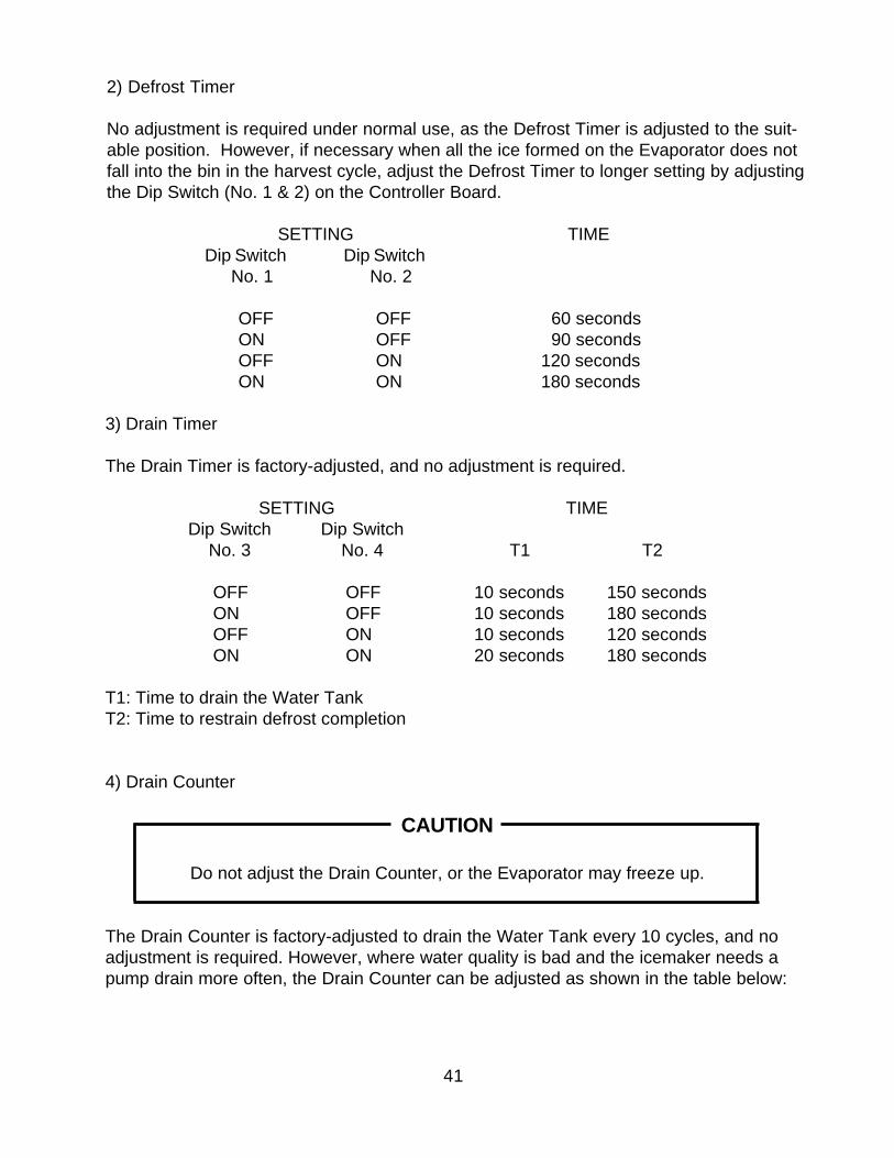
3) Drain Timer
The Drain Timer is factory-adjusted, and no adjustment is required.
SETTING TIMEDip Switch Dip Switch
No. 3 No. 4 T1 T2
OFF OFF 10 seconds 150 secondsON OFF 10 seconds 180 secondsOFF ON 10 seconds 120 secondsON ON 20 seconds 180 seconds
T1: Time to drain the Water TankT2: Time to restrain defrost completion
4) Drain Counter
CAUTION
Do not adjust the Drain Counter, or the Evaporator may freeze up.
The Drain Counter is factory-adjusted to drain the Water Tank every 10 cycles, and noadjustment is required. However, where water quality is bad and the icemaker needs apump drain more often, the Drain Counter can be adjusted as shown in the table below:
2) Defrost Timer
No adjustment is required under normal use, as the Defrost Timer is adjusted to the suit-able position. However, if necessary when all the ice formed on the Evaporator does notfall into the bin in the harvest cycle, adjust the Defrost Timer to longer setting by adjustingthe Dip Switch (No. 1 & 2) on the Controller Board.
SETTING TIMEDip Switch Dip Switch
No. 1 No. 2
OFF OFF 60 secondsON OFF 90 secondsOFF ON 120 secondsON ON 180 seconds
42
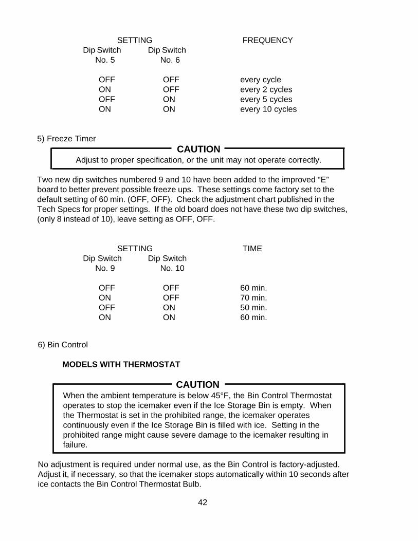
6) Bin Control
MODELS WITH THERMOSTAT
CAUTIONWhen the ambient temperature is below 45°F, the Bin Control Thermostatoperates to stop the icemaker even if the Ice Storage Bin is empty. Whenthe Thermostat is set in the prohibited range, the icemaker operatescontinuously even if the Ice Storage Bin is filled with ice. Setting in theprohibited range might cause severe damage to the icemaker resulting infailure.
No adjustment is required under normal use, as the Bin Control is factory-adjusted.Adjust it, if necessary, so that the icemaker stops automatically within 10 seconds afterice contacts the Bin Control Thermostat Bulb.
SETTING FREQUENCYDip Switch Dip Switch
No. 5 No. 6
OFF OFF every cycleON OFF every 2 cyclesOFF ON every 5 cyclesON ON every 10 cycles
5) Freeze TimerCAUTION
Adjust to proper specification, or the unit may not operate correctly.
Two new dip switches numbered 9 and 10 have been added to the improved “E”board to better prevent possible freeze ups. These settings come factory set to thedefault setting of 60 min. (OFF, OFF). Check the adjustment chart published in theTech Specs for proper settings. If the old board does not have these two dip switches,(only 8 instead of 10), leave setting as OFF, OFF.
SETTING TIMEDip Switch Dip Switch
No. 9 No. 10
OFF OFF 60 min.ON OFF 70 min.OFF ON 50 min.ON ON 60 min.
43
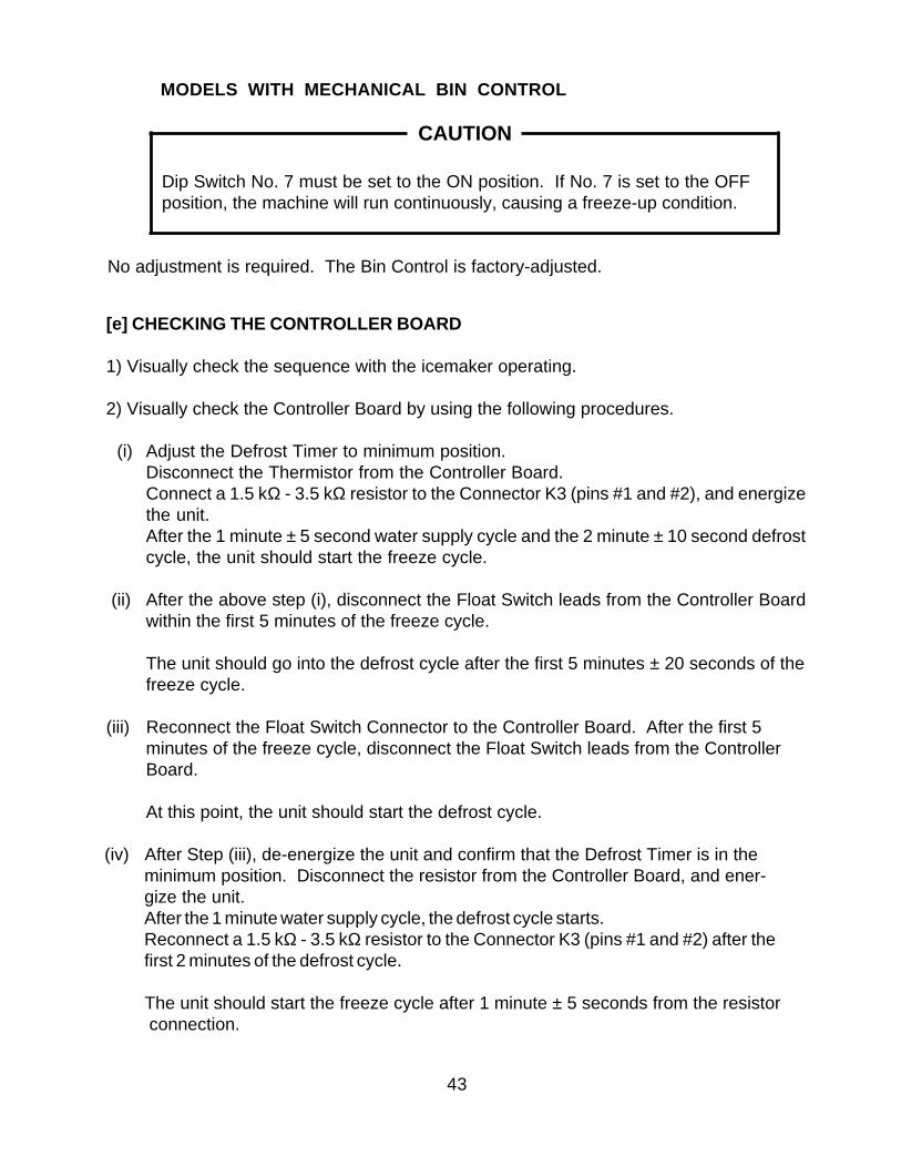
(iv) After Step (iii), de-energize the unit and confirm that the Defrost Timer is in theminimum position. Disconnect the resistor from the Controller Board, and ener-gize the unit.After the 1 minute water supply cycle, the defrost cycle starts.Reconnect a 1.5 kΩ - 3.5 kΩ resistor to the Connector K3 (pins #1 and #2) after thefirst 2 minutes of the defrost cycle.
The unit should start the freeze cycle after 1 minute ± 5 seconds from the resistor connection.
[e] CHECKING THE CONTROLLER BOARD
1) Visually check the sequence with the icemaker operating.
2) Visually check the Controller Board by using the following procedures.
(i) Adjust the Defrost Timer to minimum position.Disconnect the Thermistor from the Controller Board.Connect a 1.5 kΩ - 3.5 kΩ resistor to the Connector K3 (pins #1 and #2), and energizethe unit.After the 1 minute ± 5 second water supply cycle and the 2 minute ± 10 second defrostcycle, the unit should start the freeze cycle.
(ii) After the above step (i), disconnect the Float Switch leads from the Controller Boardwithin the first 5 minutes of the freeze cycle.
The unit should go into the defrost cycle after the first 5 minutes ± 20 seconds of thefreeze cycle.
(iii) Reconnect the Float Switch Connector to the Controller Board. After the first 5minutes of the freeze cycle, disconnect the Float Switch leads from the ControllerBoard.
At this point, the unit should start the defrost cycle.
MODELS WITH MECHANICAL BIN CONTROL
CAUTION
Dip Switch No. 7 must be set to the ON position. If No. 7 is set to the OFFposition, the machine will run continuously, causing a freeze-up condition.
No adjustment is required. The Bin Control is factory-adjusted.
44
3. SWITCHES
Two control switches are used to control operation in the KML Series Modular CrescentCubers. These switches are referred to as the “Control Switch” and the “Service Switch.”
[a] CONTROL SWITCH
The Control Switch is located on the lower left section of the control box when facingthe front of the machine. This switch is used to place the machine into one of threemodes: “Power Off” (Center position), “Ice Making” (Right position), and “Service” (Leftposition).
[b] SERVICE SWITCH
When the Control Switch is pushed to the left, the machine is placed in “Service” mode.In this position the Control Switch supplies power to the Service Switch. The ServiceSwitch can be used to perform three functions: Drain the tank (left position), Circulatewater (center position), Wash the ice making compartment (right position). When theService Switch is activated power is supplied to the pump in all three positions.
1) Drain
The KML series utilizes a pump-out drain system. When the Service Switch is activeand placed in the left position, power is supplied to the pump and the Drain solenoidvalve.
2) Wash
The KML series utilizes a solenoid operated cleaning valve. When the Service Switchis active and placed in the right position, power is supplied to the pump and the Bypasssolenoid valve. This cleans both the inside and outside of the evaporator plateassembly.
3) Circulate
When the Service switch is active and placed in the center position, power is suppliedto the pump only. This operation can be used to circulate cleaner for extended periodsof time over the outside surface of the Evaporator.
3) Check the Controller Board by using test program of the Controller Board.
The Output Test Switch “S3” provides a relay sequence test. With power OFF, place S3on and switch power to ICE. The correct lighting sequence should be none, 2, 3, 4, 1, and4, normal sequence every 5 seconds. S3 should remain in the “OFF” position for normaloperation.
45
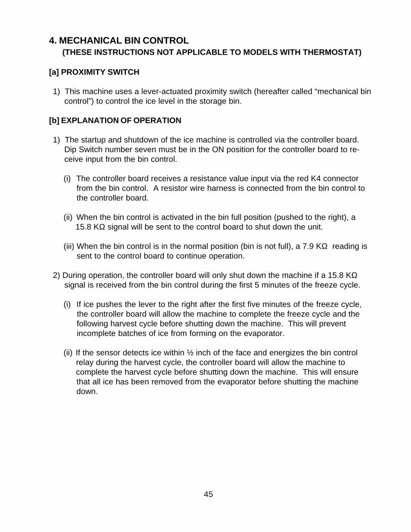
4. MECHANICAL BIN CONTROL (THESE INSTRUCTIONS NOT APPLICABLE TO MODELS WITH THERMOSTAT)
[a] PROXIMITY SWITCH
1) This machine uses a lever-actuated proximity switch (hereafter called “mechanical bincontrol”) to control the ice level in the storage bin.
[b] EXPLANATION OF OPERATION
1) The startup and shutdown of the ice machine is controlled via the controller board.Dip Switch number seven must be in the ON position for the controller board to re-ceive input from the bin control.
(i) The controller board receives a resistance value input via the red K4 connector from the bin control. A resistor wire harness is connected from the bin control to the controller board.
(ii) When the bin control is activated in the bin full position (pushed to the right), a 15.8 KΩ signal will be sent to the control board to shut down the unit.
(iii) When the bin control is in the normal position (bin is not full), a 7.9 KΩ reading is sent to the control board to continue operation.
2) During operation, the controller board will only shut down the machine if a 15.8 KΩsignal is received from the bin control during the first 5 minutes of the freeze cycle.
(i) If ice pushes the lever to the right after the first five minutes of the freeze cycle, the controller board will allow the machine to complete the freeze cycle and the following harvest cycle before shutting down the machine. This will prevent incomplete batches of ice from forming on the evaporator.
(ii) If the sensor detects ice within ½ inch of the face and energizes the bin control relay during the harvest cycle, the controller board will allow the machine to complete the harvest cycle before shutting down the machine. This will ensure that all ice has been removed from the evaporator before shutting the machine down.
46
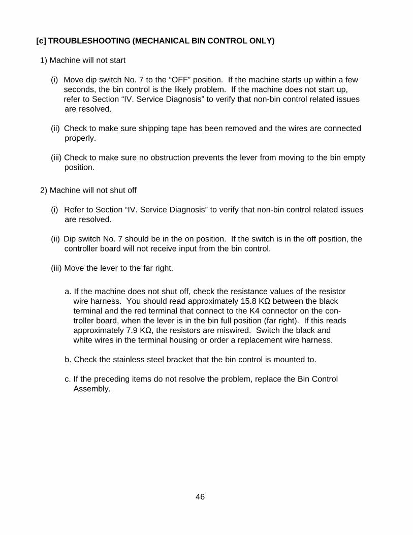
[c] TROUBLESHOOTING (MECHANICAL BIN CONTROL ONLY)
1) Machine will not start
(i) Move dip switch No. 7 to the “OFF” position. If the machine starts up within a few seconds, the bin control is the likely problem. If the machine does not start up, refer to Section “IV. Service Diagnosis” to verify that non-bin control related issues are resolved.
(ii) Check to make sure shipping tape has been removed and the wires are connected properly.
(iii) Check to make sure no obstruction prevents the lever from moving to the bin empty position.
2) Machine will not shut off
(i) Refer to Section “IV. Service Diagnosis” to verify that non-bin control related issues are resolved.
(ii) Dip switch No. 7 should be in the on position. If the switch is in the off position, the controller board will not receive input from the bin control.
(iii) Move the lever to the far right.
a. If the machine does not shut off, check the resistance values of the resistorwire harness. You should read approximately 15.8 KΩ between the blackterminal and the red terminal that connect to the K4 connector on the con-troller board, when the lever is in the bin full position (far right). If this readsapproximately 7.9 KΩ, the resistors are miswired. Switch the black andwhite wires in the terminal housing or order a replacement wire harness.
b. Check the stainless steel bracket that the bin control is mounted to.
c. If the preceding items do not resolve the problem, replace the Bin ControlAssembly.
47
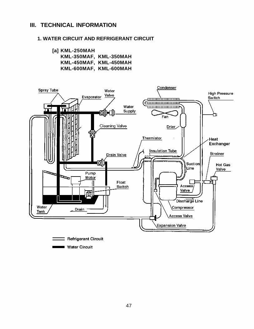
III. TECHNICAL INFORMATION
1. WATER CIRCUIT AND REFRIGERANT CIRCUIT
[a] KML-250MAHKML-350MAF, KML-350MAHKML-450MAF, KML-450MAHKML-600MAF, KML-600MAH

48
[b] KML-250MWHKML-350MWF, KML-350MWHKML-450MWF, KML-450MWHKML-600MWF, KML-600MWH
49
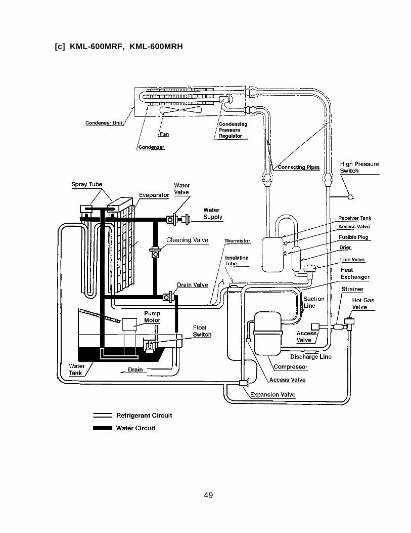
[c] KML-600MRF, KML-600MRH
50
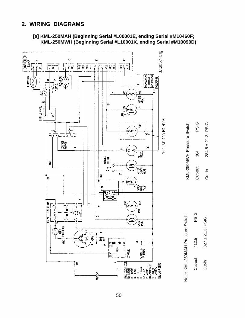
2. WIRING DIAGRAMS
[a] KML-250MAH (Beginning Serial #L00001E, ending Serial #M10460F; KML-250MWH (Beginning Serial #L10001K, ending Serial #M10090D)
Not
e:KM
L-25
0MAH
Pre
ssur
e Sw
itch
Cut
-out
412.
5
PS
IG
Cut
-in32
7 ±
21.3
PSI
G
KML-
250M
WH
Pre
ssur
e Sw
itch
Cut
-out
384
PSI
G
Cut
-in28
4.5
± 21
.3 P
SIG
51
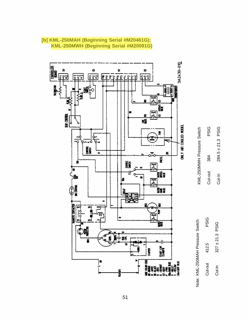
Not
e:KM
L-25
0MAH
Pre
ssur
e Sw
itch
Cut
-out
412.
5
PS
IG
Cut
-in32
7 ±
21.3
PSI
G
[b] KML-250MAH (Beginning Serial #M20461G); KML-250MWH (Beginning Serial #M20091G)
KML-
250M
WH
Pre
ssur
e Sw
itch
Cut
-out
384
PSI
G
Cut
-in28
4.5
± 21
.3 P
SIG
52
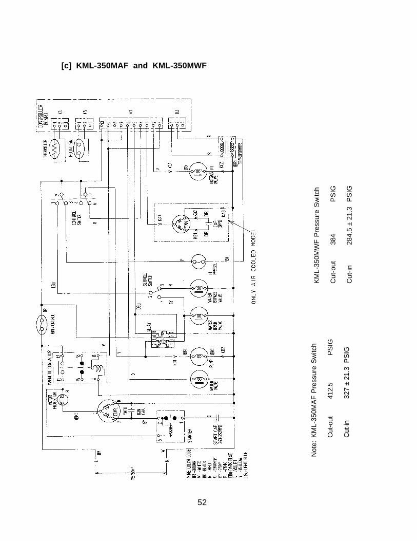
[c] KML-350MAF and KML-350MWF
Not
e:KM
L-35
0MAF
Pre
ssur
e Sw
itch
Cut
-out
412.
5
PS
IG
Cut
-in32
7 ±
21.3
PSI
G
KML-
350M
WF
Pres
sure
Sw
itch
Cut
-out
384
PSI
G
Cut
-in28
4.5
± 21
.3 P
SIG
53
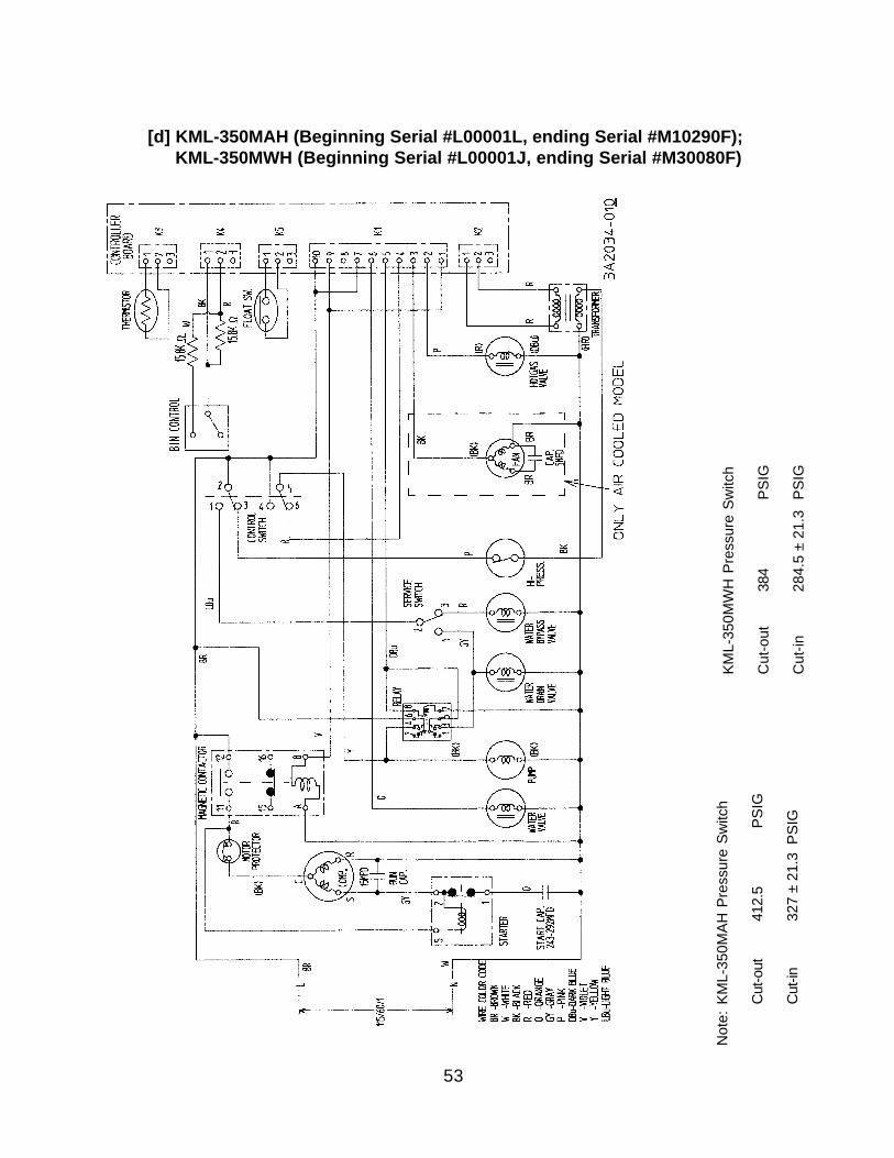
[d] KML-350MAH (Beginning Serial #L00001L, ending Serial #M10290F); KML-350MWH (Beginning Serial #L00001J, ending Serial #M30080F)
Not
e:KM
L-35
0MAH
Pre
ssur
e Sw
itch
Cut
-out
412.
5
PS
IG
Cut
-in32
7 ±
21.3
PSI
G
KML-
350M
WH
Pre
ssur
e Sw
itch
Cut
-out
384
PSI
G
Cut
-in28
4.5
± 21
.3 P
SIG
54
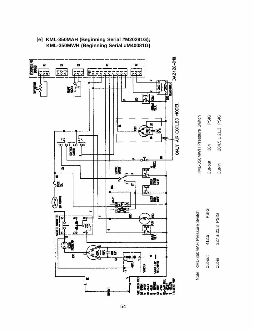
[e] KML-350MAH (Beginning Serial #M20291G); KML-350MWH (Beginning Serial #M40081G)
Not
e:KM
L-35
0MAH
Pre
ssur
e Sw
itch
Cut
-out
412.
5
PS
IG
Cut
-in32
7 ±
21.3
PSI
G
KML-
350M
WH
Pre
ssur
e Sw
itch
Cut
-out
384
PSI
G
Cut
-in28
4.5
± 21
.3 P
SIG
55
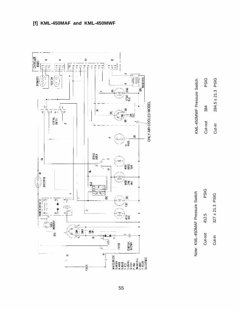
Not
e:KM
L-45
0MAF
Pre
ssur
e Sw
itch
Cut
-out
412.
5
PS
IG
Cut
-in32
7 ±
21.3
PSI
G
[f] KML-450MAF and KML-450MWF
KML-
450M
WF
Pres
sure
Sw
itch
Cut
-out
384
PSI
G
Cut
-in28
4.5
± 21
.3 P
SIG
56
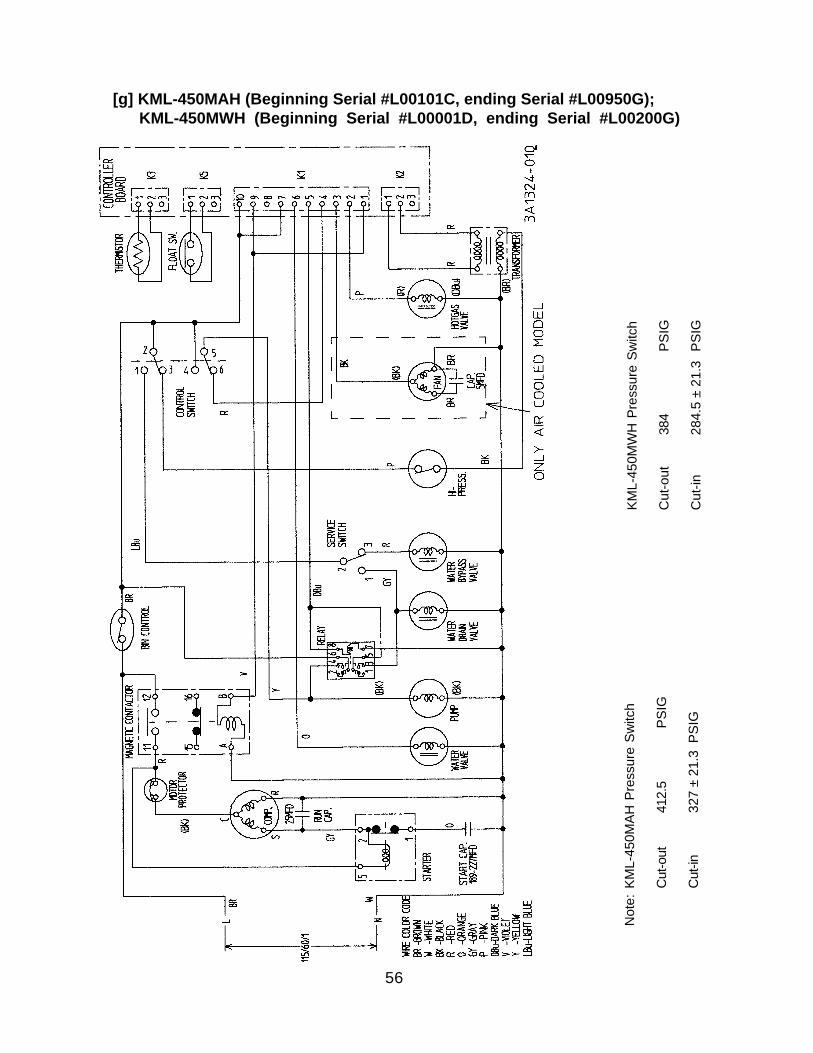
[g] KML-450MAH (Beginning Serial #L00101C, ending Serial #L00950G); KML-450MWH (Beginning Serial #L00001D, ending Serial #L00200G)
Not
e:KM
L-45
0MAH
Pre
ssur
e Sw
itch
Cut
-out
412.
5
PS
IG
Cut
-in32
7 ±
21.3
PSI
G
KML-
450M
WH
Pre
ssur
e Sw
itch
Cut
-out
384
PSI
G
Cut
-in28
4.5
± 21
.3 P
SIG
57
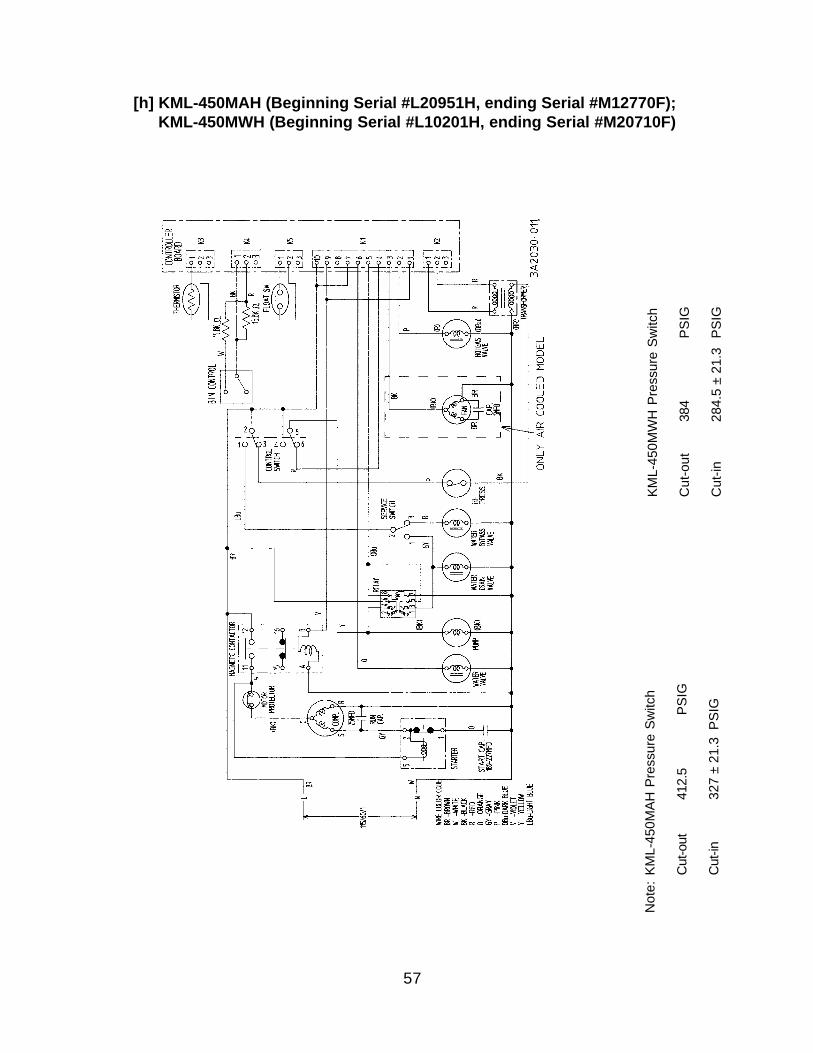
[h] KML-450MAH (Beginning Serial #L20951H, ending Serial #M12770F); KML-450MWH (Beginning Serial #L10201H, ending Serial #M20710F)
Not
e:KM
L-45
0MAH
Pre
ssur
e Sw
itch
Cut
-out
412.
5
PS
IG
Cut
-in32
7 ±
21.3
PSI
G
KML-
450M
WH
Pre
ssur
e Sw
itch
Cut
-out
384
PSI
G
Cut
-in28
4.5
± 21
.3 P
SIG
58
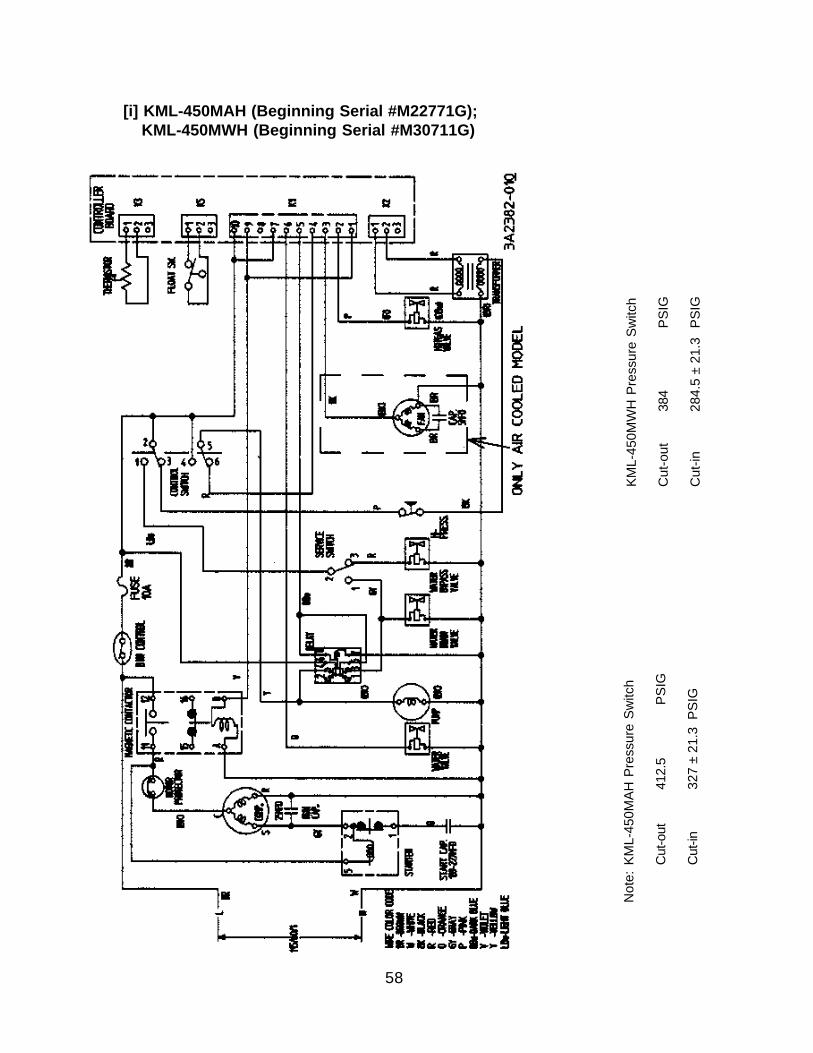
[i] KML-450MAH (Beginning Serial #M22771G); KML-450MWH (Beginning Serial #M30711G)
Not
e:KM
L-45
0MAH
Pre
ssur
e Sw
itch
Cut
-out
412.
5
PS
IG
Cut
-in32
7 ±
21.3
PSI
G
KML-
450M
WH
Pre
ssur
e Sw
itch
Cut
-out
384
PSI
G
Cut
-in28
4.5
± 21
.3 P
SIG
59
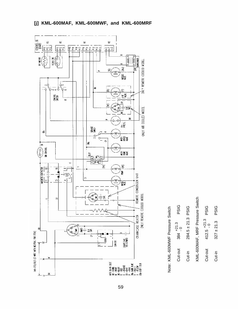
+21.
3- 0
+21.
3- 0
Not
e:KM
L-60
0MW
F Pr
essu
re S
witc
h
Cut
-out
384
PSIG
Cut
-in28
4.5
± 21
.3 P
SIG
KML-
600M
AF, M
RF
Pres
sure
Sw
itch
Cut
-out
412.
5 P
SIG
Cut
-in32
7 ±
21.3
PSI
G
[j] KML-600MAF, KML-600MWF, and KML-600MRF
60
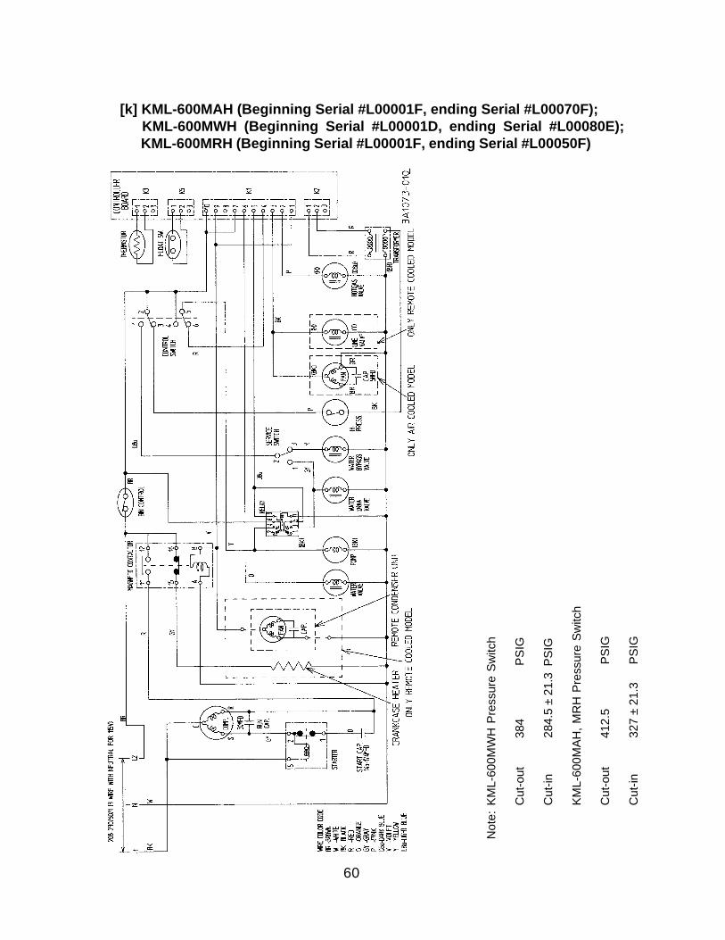
[k] KML-600MAH (Beginning Serial #L00001F, ending Serial #L00070F); KML-600MWH (Beginning Serial #L00001D, ending Serial #L00080E); KML-600MRH (Beginning Serial #L00001F, ending Serial #L00050F)
Not
e:KM
L-60
0MW
H P
ress
ure
Switc
h
Cut
-out
384
PSIG
Cut
-in28
4.5
± 21
.3 P
SIG
KML-
600M
AH, M
RH
Pre
ssur
e Sw
itch
Cut
-out
412.
5 P
SIG
Cut
-in32
7 ±
21.3
PSI
G
61
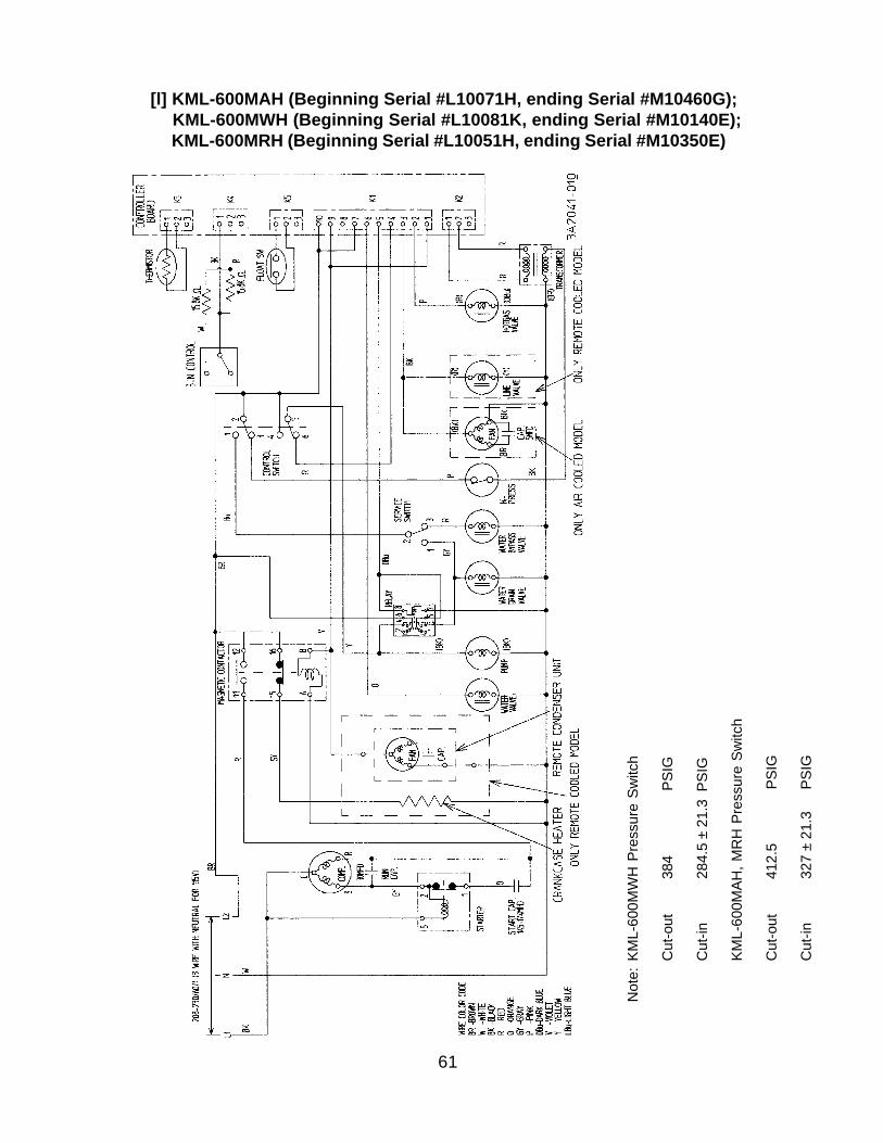
[l] KML-600MAH (Beginning Serial #L10071H, ending Serial #M10460G); KML-600MWH (Beginning Serial #L10081K, ending Serial #M10140E); KML-600MRH (Beginning Serial #L10051H, ending Serial #M10350E)
Not
e:KM
L-60
0MW
H P
ress
ure
Switc
h
Cut
-out
384
PSIG
Cut
-in28
4.5
± 21
.3 P
SIG
KML-
600M
AH, M
RH
Pre
ssur
e Sw
itch
Cut
-out
412.
5 P
SIG
Cut
-in32
7 ±
21.3
PSI
G
62
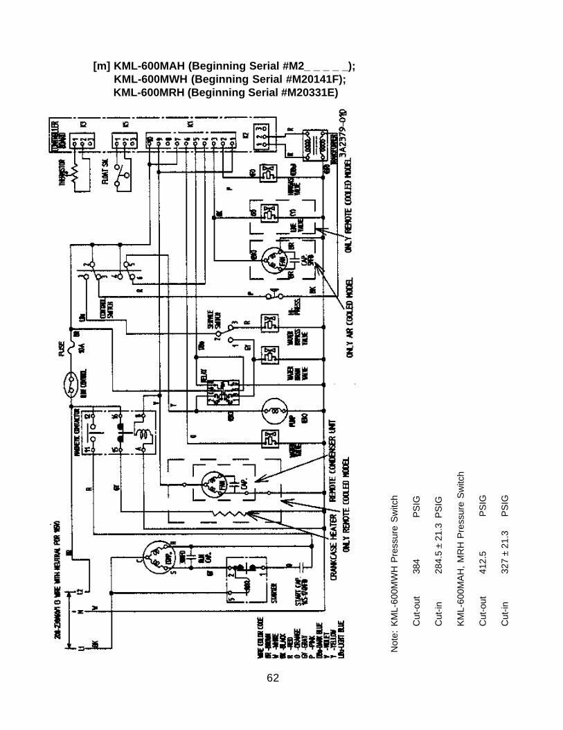
[m] KML-600MAH (Beginning Serial #M2_ _ _ _ _); KML-600MWH (Beginning Serial #M20141F); KML-600MRH (Beginning Serial #M20331E)
Not
e:KM
L-60
0MW
H P
ress
ure
Switc
h
Cut
-out
384
PSIG
Cut
-in28
4.5
± 21
.3 P
SIG
KML-
600M
AH, M
RH
Pre
ssur
e Sw
itch
Cut
-out
412.
5 P
SIG
Cut
-in32
7 ±
21.3
PSI
G
63
*
*
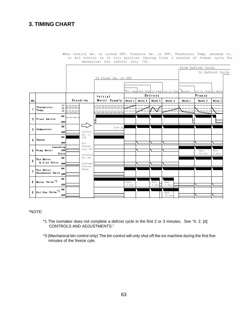
3. TIMING CHART
ControlSw. inICE
BinThermo-stat ON
PressureSw. ON
OverheatProtectReset
Hi Temp Mid Temp Lo Temp Too Lo Temp Normal Too Hi Temp Lo Water
Max. Min. 60 min 5 min
Min. Max. Max. 2 min 6 min 6 min
Max. 20 min
Time Up (60 sec)
If Float Sw. is OFF
From Defrost Cycle
When Control Sw. is turned OFF, Pressure Sw. is OFF, Thermistor Temp. exceeds t1, or Bin Control is in full position (during first 5 minutes of freeze cycle for
mechanical bin control only *3).
To Defrost Cycle
*NOTE:
*1 The icemaker does not complete a defrost cycle in the first 2 or 3 minutes. See “II. 2. [d] CONTROLS AND ADJUSTMENTS.”
*3 (Mechanical bin control only) The bin control will only shut off the ice machine during the first five minutes of the freeze cyle.
*1
*1
64
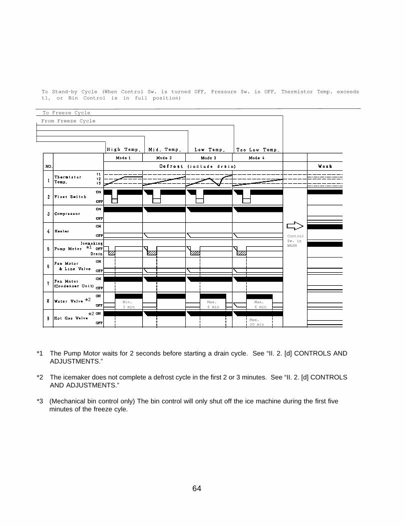
To Stand-by Cycle (When Control Sw. is turned OFF, Pressure Sw. is OFF, Thermistor Temp. exceedst1, or Bin Control is in full position)
To Freeze Cycle
From Freeze Cycle
ControlSw. inWASH
Max. 20 min
*1 The Pump Motor waits for 2 seconds before starting a drain cycle. See “II. 2. [d] CONTROLS ANDADJUSTMENTS.”
*2 The icemaker does not complete a defrost cycle in the first 2 or 3 minutes. See “II. 2. [d] CONTROLSAND ADJUSTMENTS.”
*3 (Mechanical bin control only) The bin control will only shut off the ice machine during the first five minutes of the freeze cyle.
*2
*2
*1
Min. Max. Max. 3 min 6 min 6 min
65
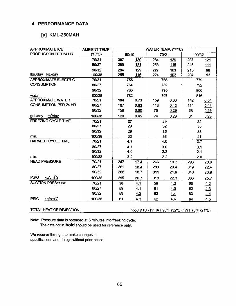
4. PERFORMANCE DATA
[a] KML-250MAH
66
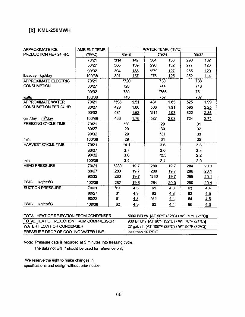
[b] KML-250MWH
67
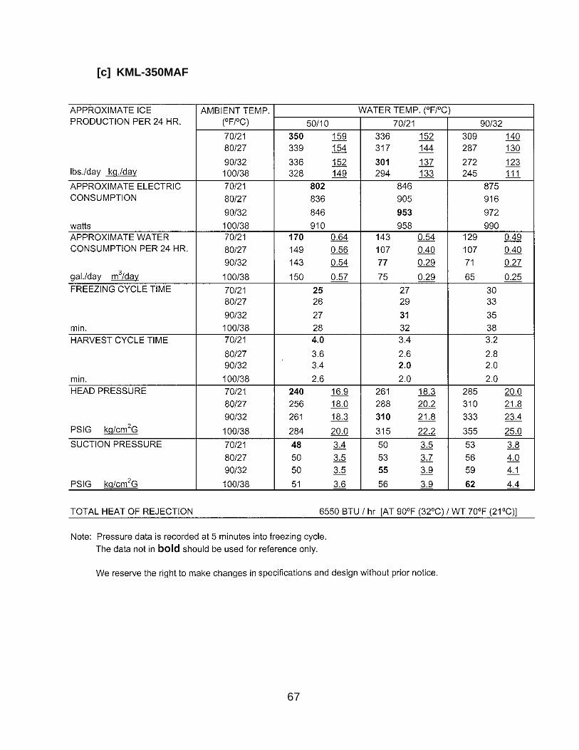
[c] KML-350MAF
68
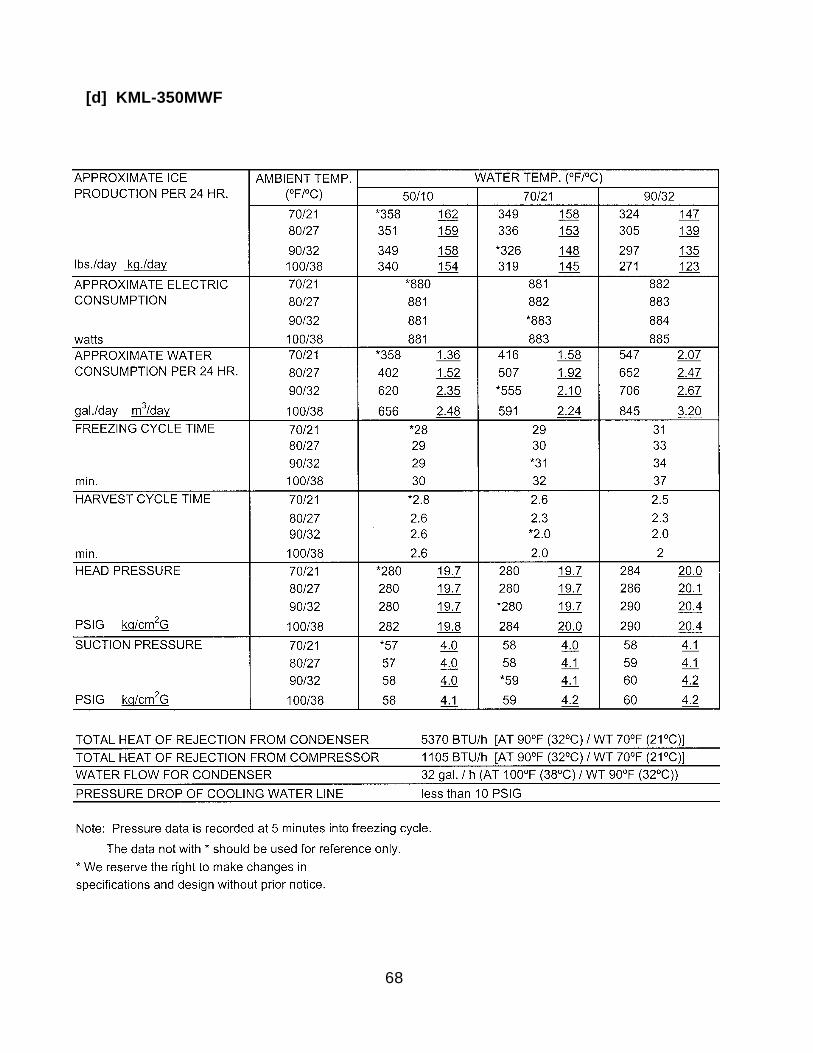
[d] KML-350MWF
69
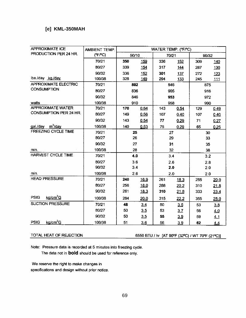
[e] KML-350MAH
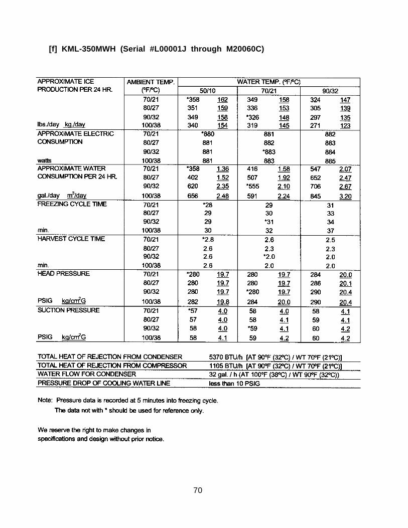
70
[f] KML-350MWH (Serial #L00001J through M20060C)

71
[g] KML-350MWH (Beginning Serial #M30061E)
72
[h] KML-450MAF
73
[i] KML-450MWF
74
[j] KML-450MAH
75
[k] KML-450MWH (Serial #L00001D through M10530B)
76
[l] KML-450MWH (Beginning Serial #M20531D)
77
[m] KML-600MAF
78
[n] KML-600MWF
79
[o] KML-600MRF
80
[p] KML-600MAH
81
[q] KML-600MWH (Serial #L00001D through Serial #M10115C)
82
[r] KML-600MWH (Beginning Serial #M10121E)
83
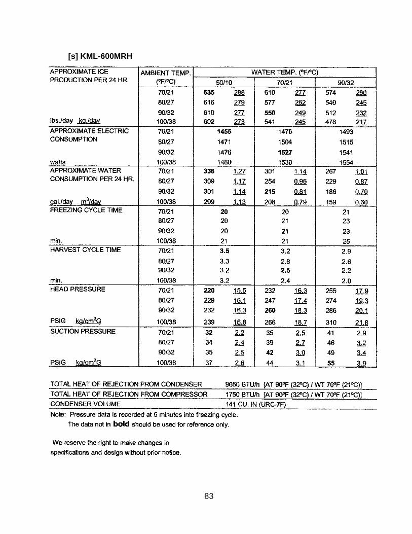
[s] KML-600MRH
84
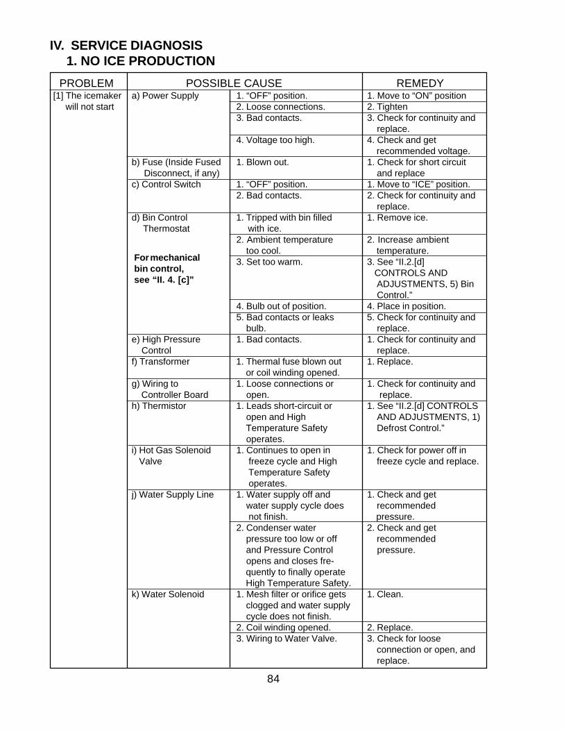
PROBLEM POSSIBLE CAUSE REMEDY[1] The icemaker a) Power Supply 1. “OFF” position. 1. Move to “ON” position will not start 2. Loose connections. 2. Tighten
3. Bad contacts. 3. Check for continuity and replace.
4. Voltage too high. 4. Check and get recommended voltage.
b) Fuse (Inside Fused 1. Blown out. 1. Check for short circuit Disconnect, if any) and replacec) Control Switch 1. “OFF” position. 1. Move to “ICE” position.
2. Bad contacts. 2. Check for continuity and replace.
d) Bin Control 1. Tripped with bin filled 1. Remove ice. Thermostat with ice.
2. Ambient temperature 2. Increase ambient too cool. temperature.3. Set too warm. 3. See “II.2.[d]
CONTROLS AND ADJUSTMENTS, 5) Bin Control.”
4. Bulb out of position. 4. Place in position.5. Bad contacts or leaks 5. Check for continuity and bulb. replace.
e) High Pressure 1. Bad contacts. 1. Check for continuity and Control replace.f) Transformer 1. Thermal fuse blown out 1. Replace.
or coil winding opened.g) Wiring to 1. Loose connections or 1. Check for continuity and Controller Board open. replace.h) Thermistor 1. Leads short-circuit or 1. See “II.2.[d] CONTROLS
open and High AND ADJUSTMENTS, 1) Temperature Safety Defrost Control.” operates.
i) Hot Gas Solenoid 1. Continues to open in 1. Check for power off in Valve freeze cycle and High freeze cycle and replace.
Temperature Safety operates.
j) Water Supply Line 1. Water supply off and 1. Check and get water supply cycle does recommended not finish. pressure.2. Condenser water 2. Check and get pressure too low or off recommended and Pressure Control pressure. opens and closes fre- quently to finally operate High Temperature Safety.
k) Water Solenoid 1. Mesh filter or orifice gets 1. Clean. clogged and water supply cycle does not finish.2. Coil winding opened. 2. Replace.3. Wiring to Water Valve. 3. Check for loose
connection or open, and replace.
IV. SERVICE DIAGNOSIS1. NO ICE PRODUCTION
For mechanicalbin control,see “II. 4. [c]”
85
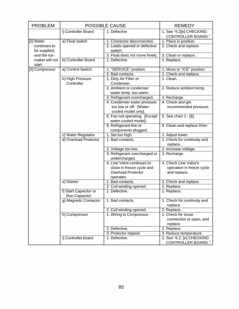
PROBLEM POSSIBLE CAUSE REMEDYl) Controller Board 1. Defective 1. See “II.2[e] CHECKING
CONTROLLER BOARD.”[2] Water a) Float switch 1. Connector disconnected. 1. Place in position. continues to 2. Leads opened or defective 2. Check and replace. be supplied, switch. and the ice- 3. Float does not move freely. 3. Clean or replace. maker will not b) Controller Board 1. Defective. 1. Replace. start.[3] Compressor a) Control Switch 1. “SERVICE” position. 1. Move to “ICE” position.
2. Bad contacts. 2. Check and replace.b) High Pressure 1. Dirty Air Filter or 1. Clean. Controller Condenser.
2. Ambient or condenser 2. Reduce ambient temp. water temp. too warm.3. Refrigerant overcharged. 3. Recharge.4. Condenser water pressure 4. Check and get too low or off. [Water- recommended pressure. cooled model only].5. Fan not operating. [Except 5. See chart 1 - [6]. water-cooled model].6. Refrigerant line or 6. Clean and replace Drier. components plugged.
c) Water Regulator 1. Set too high. 1. Adjust lower.d) Overload Protector 1. Bad contacts. 1. Check for continuity and
replace.2. Voltage too low. 2. Increase voltage.3. Refrigerant overcharged or 3. Recharge. undercharged.4. Line Valve continues to 4. Check Line Valve's close in freeze cycle and operation in freeze cycle Overload Protector and replace. operates.
e) Starter 1. Bad contacts. 1. Check and replace.2. Coil winding opened. 2. Replace.
f) Start Capacitor or 1. Defective. 1. Replace. Run Capacitorg) Magnetic Contactor 1. Bad contacts. 1. Check for continuity and
replace.2. Coil winding opened. 2. Replace.
h) Compressor 1. Wiring to Compressor. 1. Check for loose connection or open, and replace.
2. Defective. 2. Replace.3. Protector tripped. 3. Reduce temperature.
i) Controller board 1. Defective. 1. See “II.2. [e] CHECKING CONTROLLER BOARD.”
86
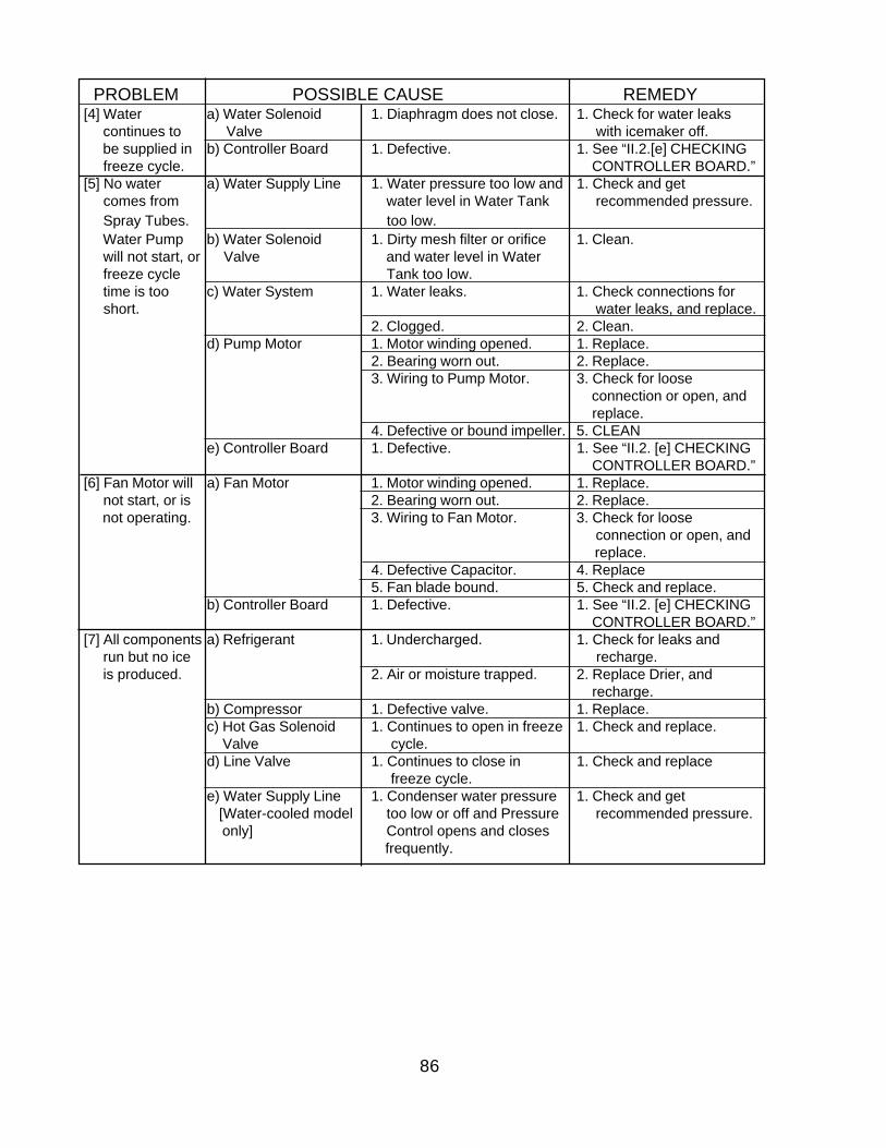
PROBLEM POSSIBLE CAUSE REMEDY[4] Water a) Water Solenoid 1. Diaphragm does not close. 1. Check for water leaks continues to Valve with icemaker off. be supplied in b) Controller Board 1. Defective. 1. See “II.2.[e] CHECKING freeze cycle. CONTROLLER BOARD.”[5] No water a) Water Supply Line 1. Water pressure too low and 1. Check and get comes from water level in Water Tank recommended pressure. Spray Tubes. too low. Water Pump b) Water Solenoid 1. Dirty mesh filter or orifice 1. Clean. will not start, or Valve and water level in Water freeze cycle Tank too low. time is too c) Water System 1. Water leaks. 1. Check connections for short. water leaks, and replace.
2. Clogged. 2. Clean.d) Pump Motor 1. Motor winding opened. 1. Replace.
2. Bearing worn out. 2. Replace.3. Wiring to Pump Motor. 3. Check for loose
connection or open, and replace.
4. Defective or bound impeller. 5. CLEANe) Controller Board 1. Defective. 1. See “II.2. [e] CHECKING
CONTROLLER BOARD.”[6] Fan Motor will a) Fan Motor 1. Motor winding opened. 1. Replace. not start, or is 2. Bearing worn out. 2. Replace. not operating. 3. Wiring to Fan Motor. 3. Check for loose
connection or open, and replace.
4. Defective Capacitor. 4. Replace5. Fan blade bound. 5. Check and replace.
b) Controller Board 1. Defective. 1. See “II.2. [e] CHECKING CONTROLLER BOARD.”
[7] All components a) Refrigerant 1. Undercharged. 1. Check for leaks and run but no ice recharge. is produced. 2. Air or moisture trapped. 2. Replace Drier, and
recharge.b) Compressor 1. Defective valve. 1. Replace.c) Hot Gas Solenoid 1. Continues to open in freeze 1. Check and replace. Valve cycle.d) Line Valve 1. Continues to close in 1. Check and replace
freeze cycle.e) Water Supply Line 1. Condenser water pressure 1. Check and get
[Water-cooled model too low or off and Pressure recommended pressure. only] Control opens and closes
frequently.
87
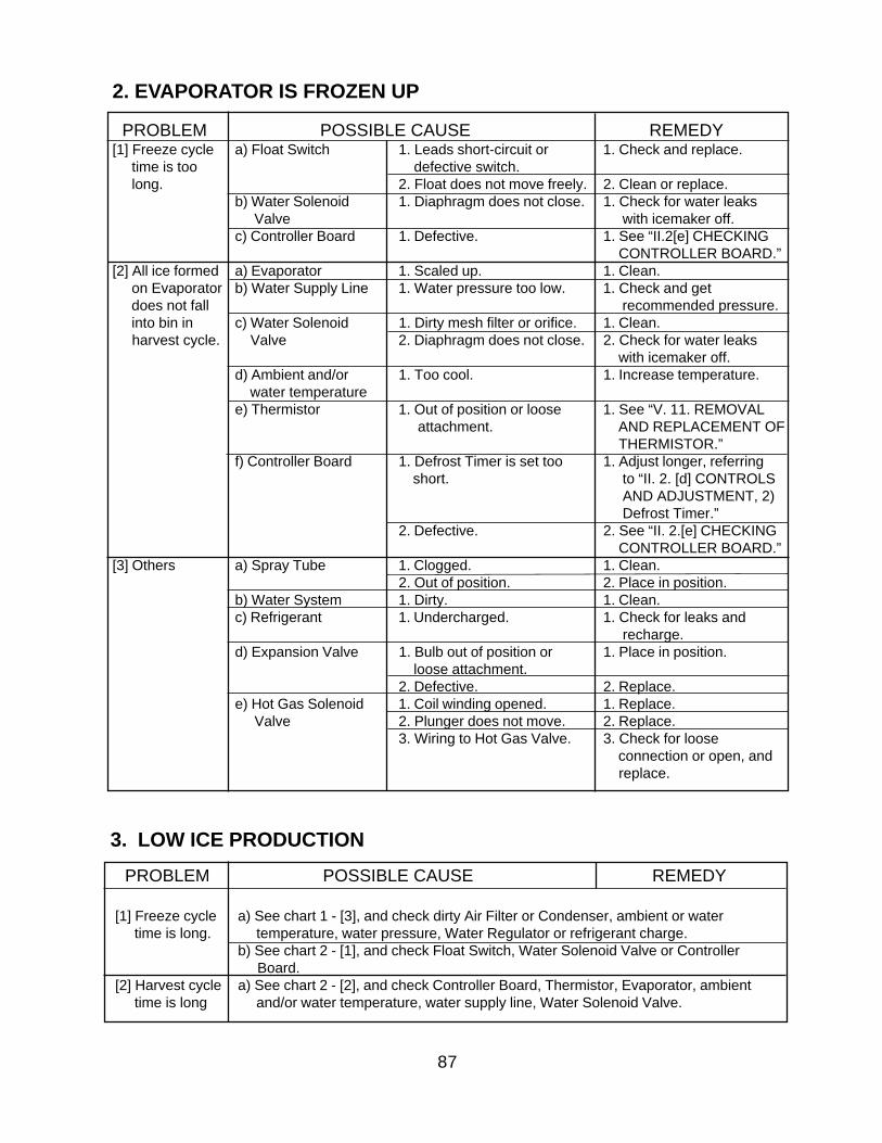
3. LOW ICE PRODUCTION
PROBLEM POSSIBLE CAUSE REMEDY[1] Freeze cycle a) Float Switch 1. Leads short-circuit or 1. Check and replace. time is too defective switch. long. 2. Float does not move freely. 2. Clean or replace.
b) Water Solenoid 1. Diaphragm does not close. 1. Check for water leaks Valve with icemaker off.c) Controller Board 1. Defective. 1. See “II.2[e] CHECKING
CONTROLLER BOARD.”[2] All ice formed a) Evaporator 1. Scaled up. 1. Clean. on Evaporator b) Water Supply Line 1. Water pressure too low. 1. Check and get does not fall recommended pressure. into bin in c) Water Solenoid 1. Dirty mesh filter or orifice. 1. Clean. harvest cycle. Valve 2. Diaphragm does not close. 2. Check for water leaks
with icemaker off.d) Ambient and/or 1. Too cool. 1. Increase temperature. water temperaturee) Thermistor 1. Out of position or loose 1. See “V. 11. REMOVAL
attachment. AND REPLACEMENT OF THERMISTOR.”
f) Controller Board 1. Defrost Timer is set too 1. Adjust longer, referring short. to “II. 2. [d] CONTROLS
AND ADJUSTMENT, 2) Defrost Timer.”
2. Defective. 2. See “II. 2.[e] CHECKING CONTROLLER BOARD.”
[3] Others a) Spray Tube 1. Clogged. 1. Clean.2. Out of position. 2. Place in position.
b) Water System 1. Dirty. 1. Clean.c) Refrigerant 1. Undercharged. 1. Check for leaks and
recharge.d) Expansion Valve 1. Bulb out of position or 1. Place in position.
loose attachment.2. Defective. 2. Replace.
e) Hot Gas Solenoid 1. Coil winding opened. 1. Replace. Valve 2. Plunger does not move. 2. Replace.
3. Wiring to Hot Gas Valve. 3. Check for loose connection or open, and replace.
2. EVAPORATOR IS FROZEN UP
PROBLEM POSSIBLE CAUSE REMEDY
[1] Freeze cycle a) See chart 1 - [3], and check dirty Air Filter or Condenser, ambient or water time is long. temperature, water pressure, Water Regulator or refrigerant charge.
b) See chart 2 - [1], and check Float Switch, Water Solenoid Valve or Controller Board.
[2] Harvest cycle a) See chart 2 - [2], and check Controller Board, Thermistor, Evaporator, ambient time is long and/or water temperature, water supply line, Water Solenoid Valve.
88
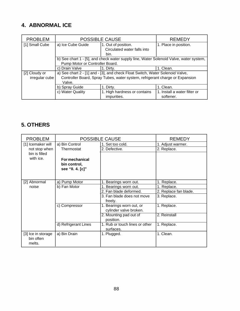
PROBLEM POSSIBLE CAUSE REMEDY[1] Icemaker will a) Bin Control 1. Set too cold. 1. Adjust warmer. not stop when Thermostat 2. Defective. 2. Replace. bin is filled with ice.
[2] Abnormal a) Pump Motor 1. Bearings worn out. 1. Replace. noise b) Fan Motor 1. Bearings worn out. 1. Replace.
2. Fan blade deformed. 2. Replace fan blade.3. Fan blade does not move 3. Replace. freely.
c) Compressor 1. Bearings worn out, or 1. Replace. cylinder valve broken.2. Mounting pad out of 2. Reinstall position.
d) Refrigerant Lines 1. Rub or touch lines or other 1. Replace. surfaces.
[3] Ice in storage a) Bin Drain 1. Plugged. 1. Clean. bin often melts.
PROBLEM POSSIBLE CAUSE REMEDY[1] Small Cube a) Ice Cube Guide 1. Out of position. 1. Place in position.
Circulated water falls into bin.
b) See chart 1 - [5], and check water supply line, Water Solenoid Valve, water system, Pump Motor or Controller Board.c) Drain Valve 1. Dirty. 1. Clean.
[2] Cloudy or a) See chart 2 - [1] and - [3], and check Float Switch, Water Solenoid Valve, irregular cube Controller Board, Spray Tubes, water system, refrigerant charge or Expansion
Valve.b) Spray Guide 1. Dirty. 1. Clean.c) Water Quality 1. High hardness or contains 1. Install a water filter or
impurities. softener.
4. ABNORMAL ICE
5. OTHERS
For mechanicalbin control,see “II. 4. [c]”
89
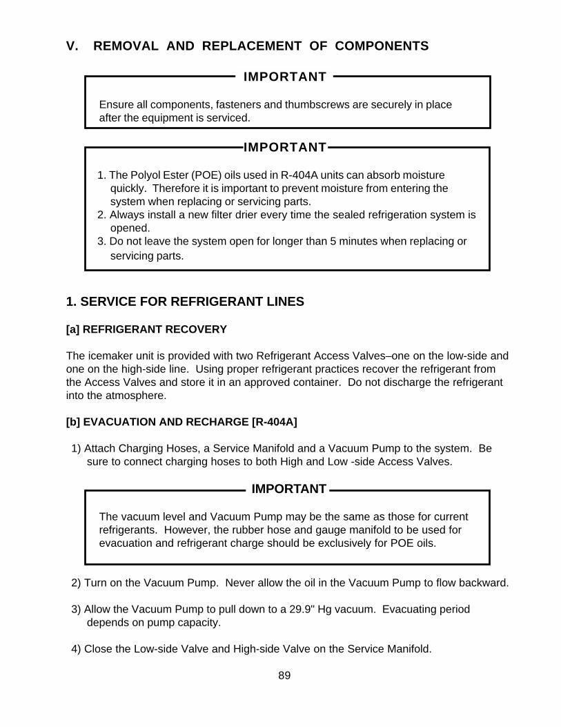
V. REMOVAL AND REPLACEMENT OF COMPONENTS
IMPORTANT
Ensure all components, fasteners and thumbscrews are securely in placeafter the equipment is serviced.
IMPORTANT
1. The Polyol Ester (POE) oils used in R-404A units can absorb moisturequickly. Therefore it is important to prevent moisture from entering thesystem when replacing or servicing parts.
2. Always install a new filter drier every time the sealed refrigeration system isopened.
3. Do not leave the system open for longer than 5 minutes when replacing orservicing parts.
1. SERVICE FOR REFRIGERANT LINES
[a] REFRIGERANT RECOVERY
The icemaker unit is provided with two Refrigerant Access Valves–one on the low-side andone on the high-side line. Using proper refrigerant practices recover the refrigerant fromthe Access Valves and store it in an approved container. Do not discharge the refrigerantinto the atmosphere.
[b] EVACUATION AND RECHARGE [R-404A]
1) Attach Charging Hoses, a Service Manifold and a Vacuum Pump to the system. Besure to connect charging hoses to both High and Low -side Access Valves.
IMPORTANT
The vacuum level and Vacuum Pump may be the same as those for currentrefrigerants. However, the rubber hose and gauge manifold to be used forevacuation and refrigerant charge should be exclusively for POE oils.
2) Turn on the Vacuum Pump. Never allow the oil in the Vacuum Pump to flow backward.
3) Allow the Vacuum Pump to pull down to a 29.9" Hg vacuum. Evacuating perioddepends on pump capacity.
4) Close the Low-side Valve and High-side Valve on the Service Manifold.
90
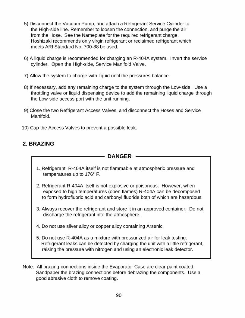
5) Disconnect the Vacuum Pump, and attach a Refrigerant Service Cylinder tothe High-side line. Remember to loosen the connection, and purge the airfrom the Hose. See the Nameplate for the required refrigerant charge.Hoshizaki recommends only virgin refrigerant or reclaimed refrigerant whichmeets ARI Standard No. 700-88 be used.
6) A liquid charge is recommended for charging an R-404A system. Invert the servicecylinder. Open the High-side, Service Manifold Valve.
7) Allow the system to charge with liquid until the pressures balance.
8) If necessary, add any remaining charge to the system through the Low-side. Use athrottling valve or liquid dispensing device to add the remaining liquid charge throughthe Low-side access port with the unit running.
9) Close the two Refrigerant Access Valves, and disconnect the Hoses and ServiceManifold.
10) Cap the Access Valves to prevent a possible leak.
2. BRAZING
DANGER
1. Refrigerant R-404A itself is not flammable at atmospheric pressure and temperatures up to 176° F.
2. Refrigerant R-404A itself is not explosive or poisonous. However, when exposed to high temperatures (open flames) R-404A can be decomposed
to form hydrofluoric acid and carbonyl fluoride both of which are hazardous.
3. Always recover the refrigerant and store it in an approved container. Do not discharge the refrigerant into the atmosphere.
4. Do not use silver alloy or copper alloy containing Arsenic.
5. Do not use R-404A as a mixture with pressurized air for leak testing. Refrigerant leaks can be detected by charging the unit with a little refrigerant,
raising the pressure with nitrogen and using an electronic leak detector.
Note: All brazing-connections inside the Evaporator Case are clear-paint coated.Sandpaper the brazing connections before debrazing the components. Use agood abrasive cloth to remove coating.
91
3. REMOVAL AND REPLACEMENT OF COMPRESSOR
IMPORTANT
Always install a new Drier every time the sealed refrigeration system is opened.Do not replace the Drier until after all other repair or replacement has beenmade.
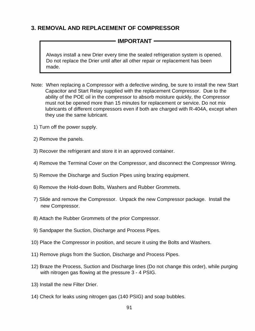
Note: When replacing a Compressor with a defective winding, be sure to install the new StartCapacitor and Start Relay supplied with the replacement Compressor. Due to theability of the POE oil in the compressor to absorb moisture quickly, the Compressormust not be opened more than 15 minutes for replacement or service. Do not mixlubricants of different compressors even if both are charged with R-404A, except whenthey use the same lubricant.
1) Turn off the power supply.
2) Remove the panels.
3) Recover the refrigerant and store it in an approved container.
4) Remove the Terminal Cover on the Compressor, and disconnect the Compressor Wiring.
5) Remove the Discharge and Suction Pipes using brazing equipment.
6) Remove the Hold-down Bolts, Washers and Rubber Grommets.
7) Slide and remove the Compressor. Unpack the new Compressor package. Install thenew Compressor.
8) Attach the Rubber Grommets of the prior Compressor.
9) Sandpaper the Suction, Discharge and Process Pipes.
10) Place the Compressor in position, and secure it using the Bolts and Washers.
11) Remove plugs from the Suction, Discharge and Process Pipes.
12) Braze the Process, Suction and Discharge lines (Do not change this order), while purgingwith nitrogen gas flowing at the pressure 3 - 4 PSIG.
13) Install the new Filter Drier.
14) Check for leaks using nitrogen gas (140 PSIG) and soap bubbles.
92
4. REMOVAL AND REPLACEMENT OF DRIER
IMPORTANT
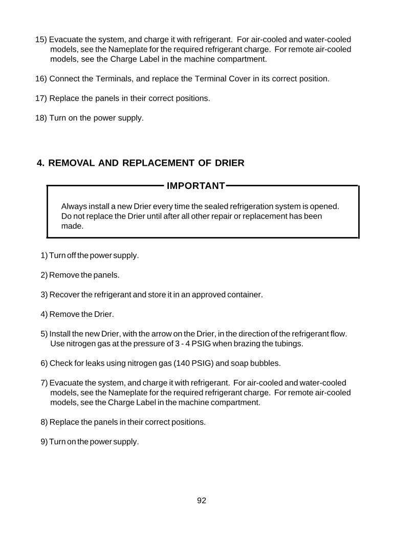
Always install a new Drier every time the sealed refrigeration system is opened.Do not replace the Drier until after all other repair or replacement has beenmade.
1) Turn off the power supply.
2) Remove the panels.
3) Recover the refrigerant and store it in an approved container.
4) Remove the Drier.
5) Install the new Drier, with the arrow on the Drier, in the direction of the refrigerant flow.Use nitrogen gas at the pressure of 3 - 4 PSIG when brazing the tubings.
6) Check for leaks using nitrogen gas (140 PSIG) and soap bubbles.
7) Evacuate the system, and charge it with refrigerant. For air-cooled and water-cooledmodels, see the Nameplate for the required refrigerant charge. For remote air-cooledmodels, see the Charge Label in the machine compartment.
8) Replace the panels in their correct positions.
9) Turn on the power supply.
15) Evacuate the system, and charge it with refrigerant. For air-cooled and water-cooledmodels, see the Nameplate for the required refrigerant charge. For remote air-cooledmodels, see the Charge Label in the machine compartment.
16) Connect the Terminals, and replace the Terminal Cover in its correct position.
17) Replace the panels in their correct positions.
18) Turn on the power supply.
93
5. REMOVAL AND REPLACEMENT OF EXPANSION VALVE
IMPORTANT
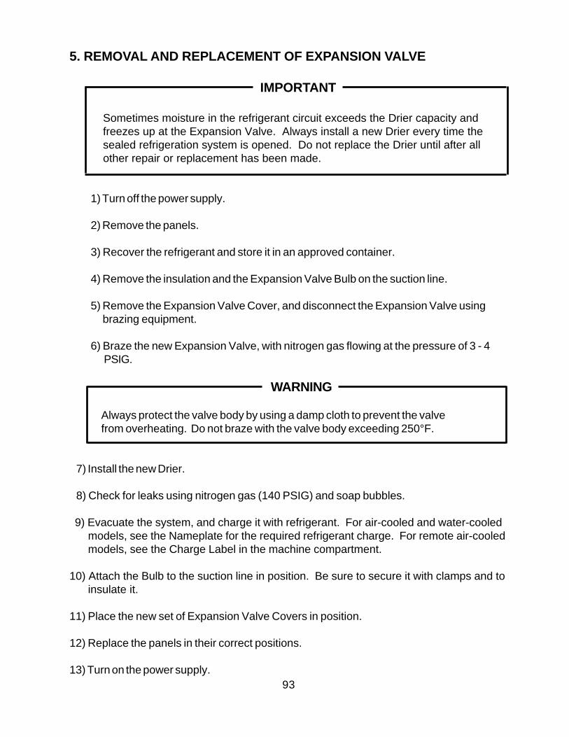
Sometimes moisture in the refrigerant circuit exceeds the Drier capacity andfreezes up at the Expansion Valve. Always install a new Drier every time thesealed refrigeration system is opened. Do not replace the Drier until after allother repair or replacement has been made.
1) Turn off the power supply.
2) Remove the panels.
3) Recover the refrigerant and store it in an approved container.
4) Remove the insulation and the Expansion Valve Bulb on the suction line.
5) Remove the Expansion Valve Cover, and disconnect the Expansion Valve using brazing equipment.
6) Braze the new Expansion Valve, with nitrogen gas flowing at the pressure of 3 - 4PSIG.
WARNING
Always protect the valve body by using a damp cloth to prevent the valvefrom overheating. Do not braze with the valve body exceeding 250°F.
7) Install the new Drier.
8) Check for leaks using nitrogen gas (140 PSIG) and soap bubbles.
9) Evacuate the system, and charge it with refrigerant. For air-cooled and water-cooledmodels, see the Nameplate for the required refrigerant charge. For remote air-cooledmodels, see the Charge Label in the machine compartment.
10) Attach the Bulb to the suction line in position. Be sure to secure it with clamps and toinsulate it.
11) Place the new set of Expansion Valve Covers in position.
12) Replace the panels in their correct positions.
13) Turn on the power supply.
94
6. REMOVAL AND REPLACEMENT OF HOT GAS VALVE AND LINEVALVE
CAUTION
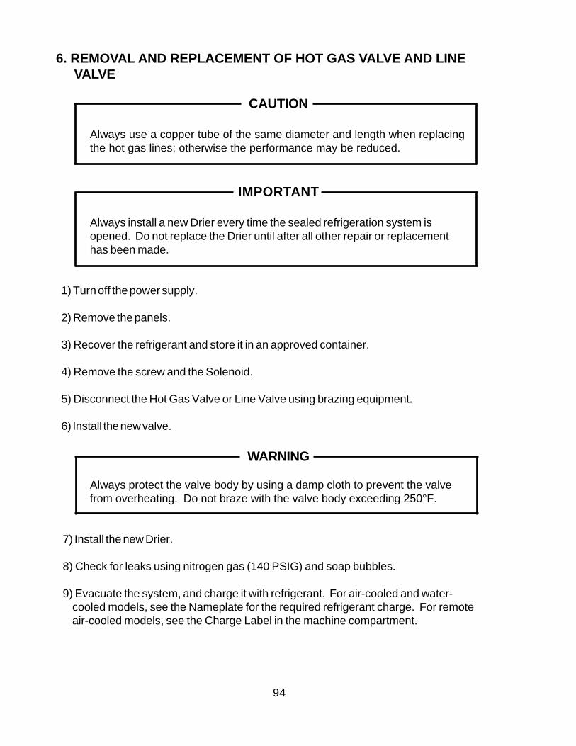
Always use a copper tube of the same diameter and length when replacingthe hot gas lines; otherwise the performance may be reduced.
IMPORTANT
Always install a new Drier every time the sealed refrigeration system isopened. Do not replace the Drier until after all other repair or replacementhas been made.
1) Turn off the power supply.
2) Remove the panels.
3) Recover the refrigerant and store it in an approved container.
4) Remove the screw and the Solenoid.
5) Disconnect the Hot Gas Valve or Line Valve using brazing equipment.
6) Install the new valve.
WARNING
Always protect the valve body by using a damp cloth to prevent the valvefrom overheating. Do not braze with the valve body exceeding 250°F.
7) Install the new Drier.
8) Check for leaks using nitrogen gas (140 PSIG) and soap bubbles.
9) Evacuate the system, and charge it with refrigerant. For air-cooled and water- cooled models, see the Nameplate for the required refrigerant charge. For remote air-cooled models, see the Charge Label in the machine compartment.
95
10) Cut the leads of the Solenoid allowing enough lead length to reconnect using closed end connectors.
11) Connect the new Solenoid leads.
12) Attach the Solenoid to the valve body, and secure it with a screw.
13) Replace the panels in their correct positions.
14) Turn on the power supply.
96
7. REMOVAL AND REPLACEMENT OF EVAPORATOR
IMPORTANT
Always install a new Drier every time the sealed refrigeration system isopened. Do not replace the Drier until after all other repairs or replacementhave been made.
1) Turn off the power supply.
2) Remove the panels and the Top Insulation over the Evaporator.
3) Recover the refrigerant and store it in an approved container.
4) Remove the Spray Tubes and the Insulations at the “U” shaped notch where therefrigeration tubings go through the molded chassis.
5) Remove the Insulation Tube, and disconnect the Evaporator Inlet Tubing at the Tee next to the Expansion Valve.
6) Lift up the Evaporator, and disconnect the Evaporator Outlet Tubing.
7) Install the new Evaporator.
8) Install the new Drier.
9) Check for leaks using nitrogen gas (140 PSIG) and soap bubbles.
10) Evacuate the system, and charge it with refrigerant. For air-cooled and water- cooled models, see the Nameplate for the required refrigerant charge. For remote air-cooled models, see the Charge Label in the machine compartment.
11) Replace the removed parts in the reverse order of which they were removed.
12) Replace the Top Insulation and the panels in their correct positions.
13) Turn on the power supply.
97
8. REMOVAL AND REPLACEMENT OF WATER REGULATING VALVE -WATER-COOLED MODEL ONLY
IMPORTANT
Always install a new Drier every time the sealed refrigeration system isopened. Do not replace the Drier until after all other repair or replacementhas been made.
1) Turn off the power supply.
2) Close the Water Supply Line Shut-off Valve.
3) Remove the panels.
4) Recover the refrigerant and store it in an approved container.
5) Disconnect the Capillary Tube at the Condenser outlet using brazing equipment.
6) Disconnect the Flare-connections of the valve.
7) Remove the screws and the valve from the Bracket.
8) Install the new valve, and braze the Capillary Tube.
9) Install the new Drier.
10) Check for leaks using nitrogen gas (140 PSIG) and soap bubbles.
11) Evacuate the system, and charge it with refrigerant. See the Nameplate for the required refrigerant charge.
12) Connect the Flare-connections.
13) Open the Water Supply Line Shut-off Valve.
14) Check for water leaks.
15) Replace the panels in their correct positions.
16) Turn on the power supply.
98
9. ADJUSTMENT OF WATER REGULATING VALVE - WATER-COOLEDMODEL ONLY
The Water Regulating Valve (also called “WATER REGULATOR”) is factory-adjusted.No adjustment is required under normal use. Adjust the Water Regulator, if necessary,using the following procedures.
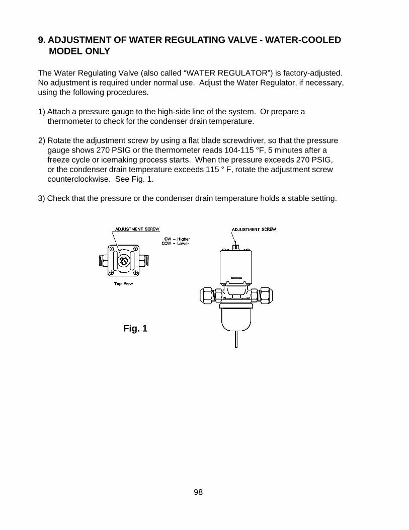
1) Attach a pressure gauge to the high-side line of the system. Or prepare athermometer to check for the condenser drain temperature.
2) Rotate the adjustment screw by using a flat blade screwdriver, so that the pressuregauge shows 270 PSIG or the thermometer reads 104-115 °F, 5 minutes after afreeze cycle or icemaking process starts. When the pressure exceeds 270 PSIG,or the condenser drain temperature exceeds 115 ° F, rotate the adjustment screwcounterclockwise. See Fig. 1.
3) Check that the pressure or the condenser drain temperature holds a stable setting.
Fig. 1
99
10. REMOVAL AND REPLACEMENT OF CONDENSING PRESSURE REGULATOR (C.P.R.) - REMOTE AIR-COOLED MODEL ONLY
IMPORTANT
Always install a new Drier every time the sealed refrigeration system isopened. Do not replace the Drier until after all other repair or replacementhas been made.
1) Turn off the power supply.
2) Remove the panels from the remote condenser unit.
3) Recover the refrigerant and store it in an approved container.
4) Before heating, break off the stub on the dome to release the dome charge.
5) Disconnect the C.P.R. using brazing equipment.
6) Install the new C.P.R. Use nitrogen gas at the pressure of 3 - 4 PSIG when brazingthe C.P.R.
WARNING
Always protect the C.P.R. body by using a damp cloth to prevent theC.P.R. from overheating. Do not braze with the C.P.R. body exceeding250° F.
7) Install the new Drier in the icemaker.
8) Check for leaks using nitrogen gas (140 PSIG) and soap bubbles.
9) Evacuate the system and charge it with refrigerant. See the Charge Label in themachine compartment in the icemaker.
10) Replace the panels in their correct positions.
11) Turn on the power supply.
100
11. REMOVAL AND REPLACEMENT OF THERMISTOR
CAUTION
1. Fragile, handle very carefully.
2. Always use a recommended sealant (High Thermal Conductive Type),Model KE4560RTV manufactured by SHINETSU SILICONE, Part Code60Y000-11, or Part Code 4A0683-01 or equivalent.
3. Always use a recommended foam insulation (Non-absorbent Type) orequivalent.
4. Do not shorten or cut the Thermistor leads when installing it.
1) Turn off the power supply.
2) Remove the panels.
3) Remove the Control Box Cover.
4) Disconnect the Thermistor leads from the K3 Connector on the Controller Board.
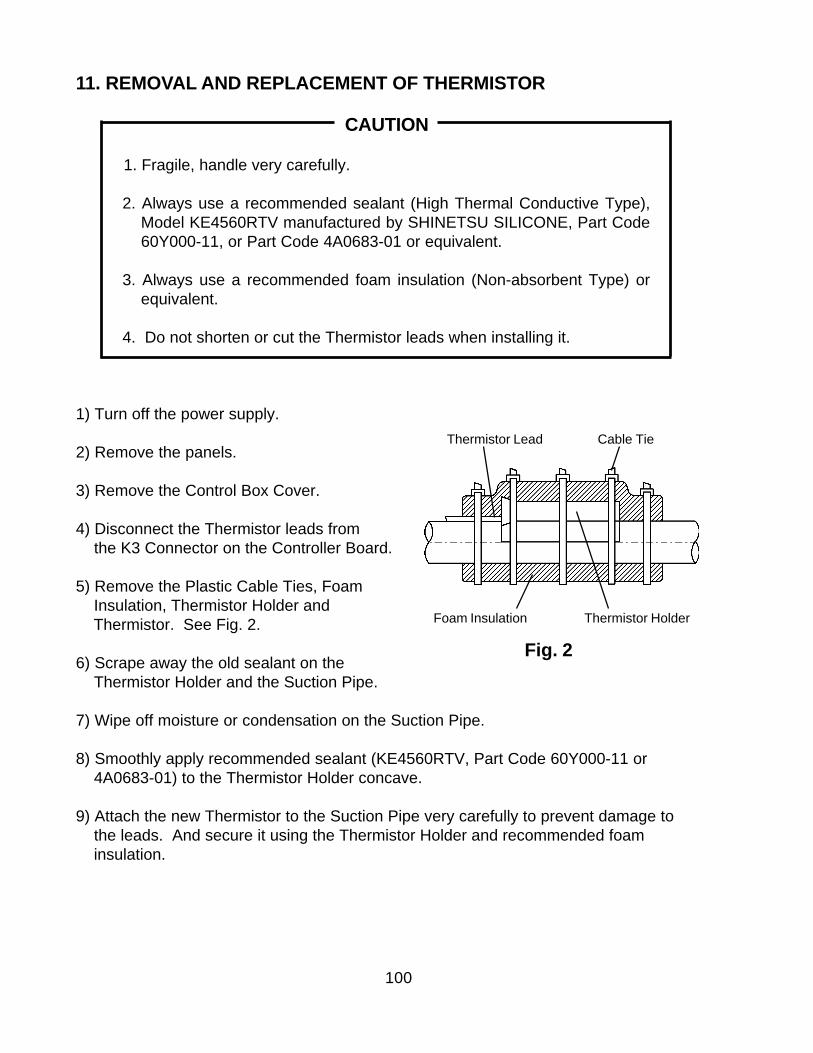
5) Remove the Plastic Cable Ties, Foam Insulation, Thermistor Holder and Thermistor. See Fig. 2.
6) Scrape away the old sealant on the Thermistor Holder and the Suction Pipe.
7) Wipe off moisture or condensation on the Suction Pipe.
8) Smoothly apply recommended sealant (KE4560RTV, Part Code 60Y000-11 or 4A0683-01) to the Thermistor Holder concave.
9) Attach the new Thermistor to the Suction Pipe very carefully to prevent damage to the leads. And secure it using the Thermistor Holder and recommended foam insulation.
Fig. 2
Foam Insulation Thermistor Holder
Thermistor Lead Cable Tie
101
10) Secure the insulation using the Plastic Cable Ties.
11) Connect the Thermistor leads through the bushing of the Control Box to the K3Connector on the Controller Board.
Note: Do not cut the leads of the Thermistor while installing it.
12) Replace the Control Box Cover and the panels in their correct positions.
13) Turn on the power supply.
12. REMOVAL AND REPLACEMENT OF FAN MOTOR
Note: When replacing a Fan Motor with defective winding, it is recommended that a new capacitor be installed.
1) Turn off the power supply.
2) Remove the panels.
3) Remove the Junction Box Cover from the remote condenser unit (Remote Air-cooled model).
4) Remove the closed end connectors from the Fan Motor leads.
5) Remove the Fan Motor Bracket and Fan Motor.
6) Install the new Fan Motor, and replace the removed parts in the reverse order of whichthey were removed.
7) Replace the panels in their correct positions.
8) Replace the Junction Box Cover in its correct position (Remote Air-cooled model).
9) Turn on the power supply.
102
13. REMOVAL AND REPLACEMENT OF WATER VALVE
1) Turn off the power supply.
2) Close the Water Supply Line Shut-off Valve.
3) Remove the Front Panel.
4) Remove the Valve Outlet Tubing by releasing the Clamp.
5) Remove the Bracket from the unit.
6) Remove the Fitting Nut and Water Valve.
7) Disconnect the Terminals from the Water Valve.
8) Install the new Water Valve, and replace the removed parts in the reverse order of which they were removed.
9) Open the Water Supply Line Shut-off Valve.
10) Turn on the power supply.
11) Check for leaks.
12) Replace the Front Panel in its correct position.
103
15. REMOVAL AND REPLACEMENT OF SPRAY TUBES
1) Turn off the power supply.
2) Remove the Front Panel and the Insulation Panel.
3) Remove the Rubber Hoses from the Spray Tubes (Water Supply Pipe).
4) Release the Clamps, and disconnect the Rubber Hoses.
5) Remove the Spray Tubes by squeezing the side tabs.
6) Install the new Spray Tubes, and replace the removed parts in the reverse order of which they were removed.
7) Replace the panels in their correct positions.
8) Turn on the power supply.
14. REMOVAL AND REPLACEMENT OF PUMP MOTOR
1) Turn off the power supply.
2) Remove the Front Panel.
3) Remove the three screws and the Float Switch Assembly.
4) Remove the wiring connectors from the Pump Motor leads.
5) Remove the four screws and the Pump Motor.
5) Install the new Pump, and replace the removed parts in the reverse order of which they were removed.
6) Turn on the power supply, and check for leaks.
7) Replace the Front Panel in its correct position.
104
VI. MAINTENANCE AND CLEANING INSTRUCTIONS
IMPORTANT
Ensure all components, fasteners and thumbscrews are securely in place afterany maintenance or cleaning is done to the equipment.
1. PREPARING THE ICEMAKER FOR LONG STORAGE
WARNING
When shutting off the icemaker for an extended time, drain out all water fromthe water tank and remove the ice from the Storage Bin. TheStorage Bin should be cleaned and dried. Drain the icemaker to preventdamage to the water supply line at sub-freezing temperatures, using air orcarbon dioxide. Shut off the icemaker until the proper ambient temperatureis resumed.
• When the icemaker is not used for two or three days, it is sufficient to only move theControl Switch to the “OFF” position, unless the icemaker will be at sub-freezingtemperatures.
[1] On water-cooled model only, first remove the water from the water-cooled condenser:
1) Turn off the power supply.
2) Remove the Front Panel.
3) Move the Control Switch, on the Control Box, to the “OFF” position.
4) Wait 3 minutes.
5) Move the Control Switch to the “ICE” position.
6) Replace the Front Panel and turn on the power supply.
7) Allow 5 minutes for the icemaker to fill with water and the Water Pump to start operating.
8) Close the Water-cooled Condenser Water Supply Line Shut-off Valve.
9) Open the Drain Valve for the water-cooled condenser water supply line.
105
[2] Remove the water from the potable water supply line:
1) Turn off the power supply and remove the Front Panel.
2) Move the Control Switch, on the Control Box, to the “OFF” position.
3) Wait 3 minutes.
4) Close the Potable Water Supply Line Shut-off Valve and open the Potable WaterSupply Line Drain Valve.
5) Allow the line to drain by gravity.
6) Attach compressed air or carbon dioxide supply to the Potable Water Line Drain Valve.
7) Move the Control Switch to the “ICE” position.
8) Replace the Front Panel and turn on the power supply.
9) Blow the potable water line out using compressed air or carbon dioxide.
[3] Drain the Potable Water Tank:
1) Turn off the power supply.
2) Remove the Front Panel.
3) Move the Control Switch to “SERVICE” and move the Service Switch to the “DRAIN” position
4) Replace the Front Panel and turn on the power supply for 2 minutes.
5) Turn off the power supply.
10) Allow the line to drain by gravity.
11) Attach compressed air or carbon dioxide supply to the Condenser Water Line DrainValve.
12) Blow the water-cooled Condenser out, using compressed air or carbon dioxide until water stops coming out.
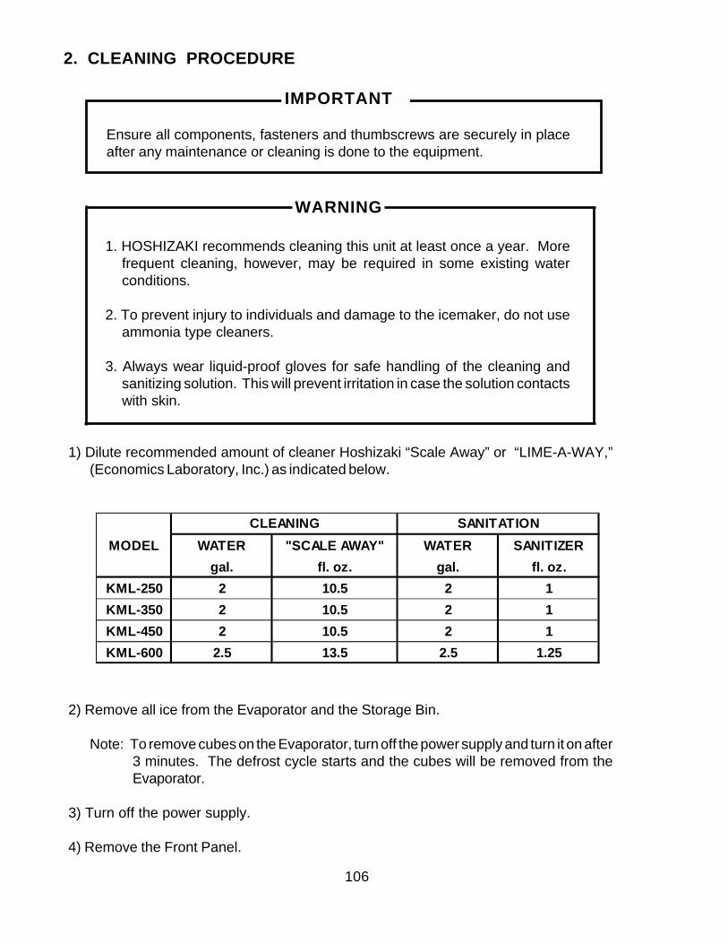
106
MODEL WATER "SCALE AWAY" WATER SANITIZERgal. fl. oz. gal. fl. oz.
KML-250 2 10.5 2 1KML-350 2 10.5 2 1KML-450 2 10.5 2 1KML-600 2.5 13.5 2.5 1.25
CLEANING SANITATION
2. CLEANING PROCEDURE
IMPORTANT
Ensure all components, fasteners and thumbscrews are securely in placeafter any maintenance or cleaning is done to the equipment.
WARNING
1. HOSHIZAKI recommends cleaning this unit at least once a year. Morefrequent cleaning, however, may be required in some existing waterconditions.
2. To prevent injury to individuals and damage to the icemaker, do not useammonia type cleaners.
3. Always wear liquid-proof gloves for safe handling of the cleaning andsanitizing solution. This will prevent irritation in case the solution contactswith skin.
1) Dilute recommended amount of cleaner Hoshizaki “Scale Away” or “LIME-A-WAY,”(Economics Laboratory, Inc.) as indicated below.
2) Remove all ice from the Evaporator and the Storage Bin.
Note: To remove cubes on the Evaporator, turn off the power supply and turn it on after3 minutes. The defrost cycle starts and the cubes will be removed from theEvaporator.
3) Turn off the power supply.
4) Remove the Front Panel.
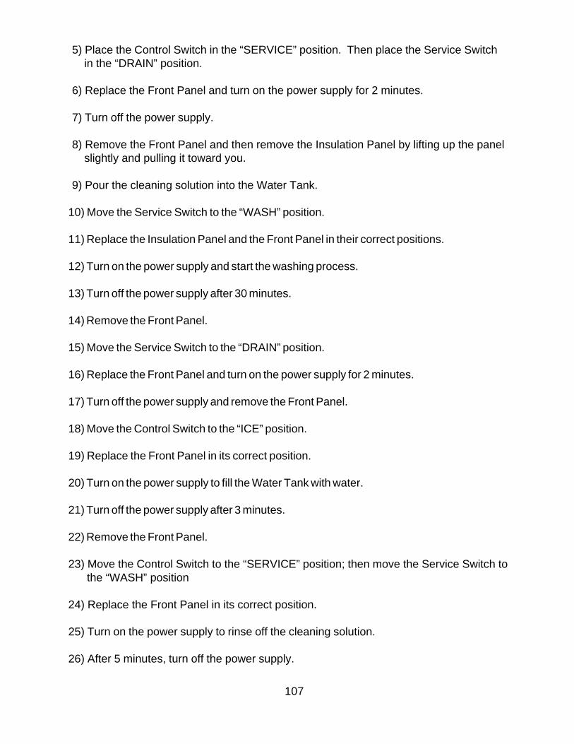
107
5) Place the Control Switch in the “SERVICE” position. Then place the Service Switch in the “DRAIN” position.
6) Replace the Front Panel and turn on the power supply for 2 minutes.
7) Turn off the power supply.
8) Remove the Front Panel and then remove the Insulation Panel by lifting up the panel slightly and pulling it toward you.
9) Pour the cleaning solution into the Water Tank.
10) Move the Service Switch to the “WASH” position.
11) Replace the Insulation Panel and the Front Panel in their correct positions.
12) Turn on the power supply and start the washing process.
13) Turn off the power supply after 30 minutes.
14) Remove the Front Panel.
15) Move the Service Switch to the “DRAIN” position.
16) Replace the Front Panel and turn on the power supply for 2 minutes.
17) Turn off the power supply and remove the Front Panel.
18) Move the Control Switch to the “ICE” position.
19) Replace the Front Panel in its correct position.
20) Turn on the power supply to fill the Water Tank with water.
21) Turn off the power supply after 3 minutes.
22) Remove the Front Panel.
23) Move the Control Switch to the “SERVICE” position; then move the Service Switch tothe “WASH” position
24) Replace the Front Panel in its correct position.
25) Turn on the power supply to rinse off the cleaning solution.
26) After 5 minutes, turn off the power supply.
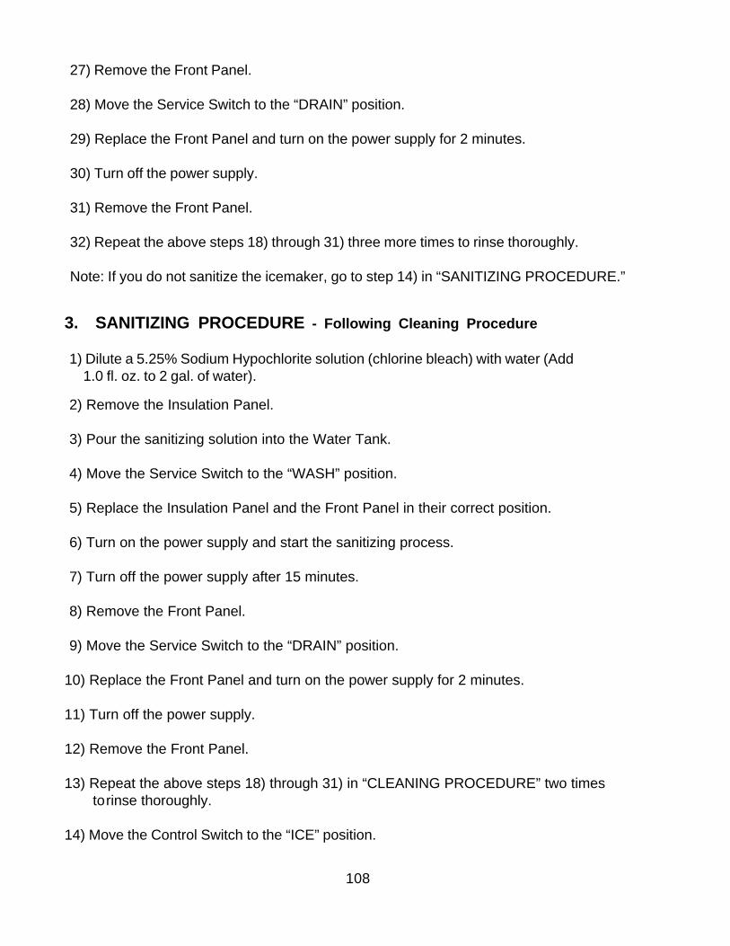
108
3. SANITIZING PROCEDURE - Following Cleaning Procedure
1) Dilute a 5.25% Sodium Hypochlorite solution (chlorine bleach) with water (Add 1.0 fl. oz. to 2 gal. of water).
2) Remove the Insulation Panel.
3) Pour the sanitizing solution into the Water Tank.
4) Move the Service Switch to the “WASH” position.
5) Replace the Insulation Panel and the Front Panel in their correct position.
6) Turn on the power supply and start the sanitizing process.
7) Turn off the power supply after 15 minutes.
8) Remove the Front Panel.
9) Move the Service Switch to the “DRAIN” position.
10) Replace the Front Panel and turn on the power supply for 2 minutes.
11) Turn off the power supply.
12) Remove the Front Panel.
13) Repeat the above steps 18) through 31) in “CLEANING PROCEDURE” two times to rinse thoroughly.
14) Move the Control Switch to the “ICE” position.
27) Remove the Front Panel.
28) Move the Service Switch to the “DRAIN” position.
29) Replace the Front Panel and turn on the power supply for 2 minutes.
30) Turn off the power supply.
31) Remove the Front Panel.
32) Repeat the above steps 18) through 31) three more times to rinse thoroughly.
Note: If you do not sanitize the icemaker, go to step 14) in “SANITIZING PROCEDURE.”
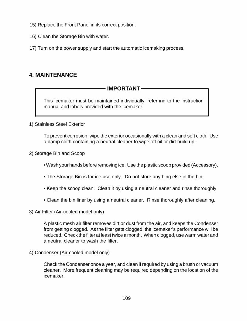
109
4. MAINTENANCE
IMPORTANT
This icemaker must be maintained individually, referring to the instructionmanual and labels provided with the icemaker.
1) Stainless Steel Exterior
To prevent corrosion, wipe the exterior occasionally with a clean and soft cloth. Usea damp cloth containing a neutral cleaner to wipe off oil or dirt build up.
2) Storage Bin and Scoop
• Wash your hands before removing ice. Use the plastic scoop provided (Accessory).
• The Storage Bin is for ice use only. Do not store anything else in the bin.
• Keep the scoop clean. Clean it by using a neutral cleaner and rinse thoroughly.
• Clean the bin liner by using a neutral cleaner. Rinse thoroughly after cleaning.
3) Air Filter (Air-cooled model only)
A plastic mesh air filter removes dirt or dust from the air, and keeps the Condenserfrom getting clogged. As the filter gets clogged, the icemaker’s performance will bereduced. Check the filter at least twice a month. When clogged, use warm water anda neutral cleaner to wash the filter.
4) Condenser (Air-cooled model only)
Check the Condenser once a year, and clean if required by using a brush or vacuumcleaner. More frequent cleaning may be required depending on the location of theicemaker.
15) Replace the Front Panel in its correct position.
16) Clean the Storage Bin with water.
17) Turn on the power supply and start the automatic icemaking process.
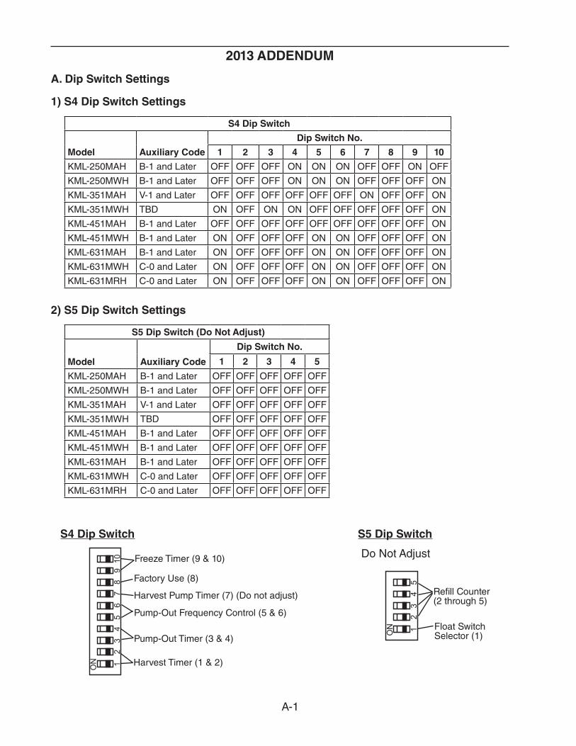
A-1
2013 ADDENDUM
A. Dip Switch Settings
1) S4 Dip Switch Settings
S4 Dip Switch
Model Auxiliary Code
Dip Switch No.
1 2 3 4 5 6 7 8 9 10
KML-250MAH B-1 and Later OFF OFF OFF ON ON ON OFF OFF ON OFF
KML-250MWH B-1 and Later OFF OFF OFF ON ON ON OFF OFF OFF ON
KML-351MAH V-1 and Later OFF OFF OFF OFF OFF OFF ON OFF OFF ON
KML-351MWH TBD ON OFF ON ON OFF OFF OFF OFF OFF ON
KML-451MAH B-1 and Later OFF OFF OFF OFF OFF OFF OFF OFF OFF ON
KML-451MWH B-1 and Later ON OFF OFF OFF ON ON OFF OFF OFF ON
KML-631MAH B-1 and Later ON OFF OFF OFF ON ON OFF OFF OFF ON
KML-631MWH C-0 and Later ON OFF OFF OFF ON ON OFF OFF OFF ON
KML-631MRH C-0 and Later ON OFF OFF OFF ON ON OFF OFF OFF ON
2) S5 Dip Switch Settings
S5 Dip Switch (Do Not Adjust)
Model Auxiliary Code
Dip Switch No.
1 2 3 4 5
KML-250MAH B-1 and Later OFF OFF OFF OFF OFF
KML-250MWH B-1 and Later OFF OFF OFF OFF OFF
KML-351MAH V-1 and Later OFF OFF OFF OFF OFF
KML-351MWH TBD OFF OFF OFF OFF OFF
KML-451MAH B-1 and Later OFF OFF OFF OFF OFF
KML-451MWH B-1 and Later OFF OFF OFF OFF OFF
KML-631MAH B-1 and Later OFF OFF OFF OFF OFF
KML-631MWH C-0 and Later OFF OFF OFF OFF OFF
KML-631MRH C-0 and Later OFF OFF OFF OFF OFF
12
34
5
ON
12
34
56
78
910
ON
Freeze Timer (9 & 10)
Pump-Out Frequency Control (5 & 6)
Pump-Out Timer (3 & 4)
Harvest Timer (1 & 2)
Harvest Pump Timer (7) (Do not adjust)
Factory Use (8)
S4 Dip Switch
Do Not Adjust
S5 Dip Switch
Refill Counter (2 through 5)
Float Switch Selector (1)
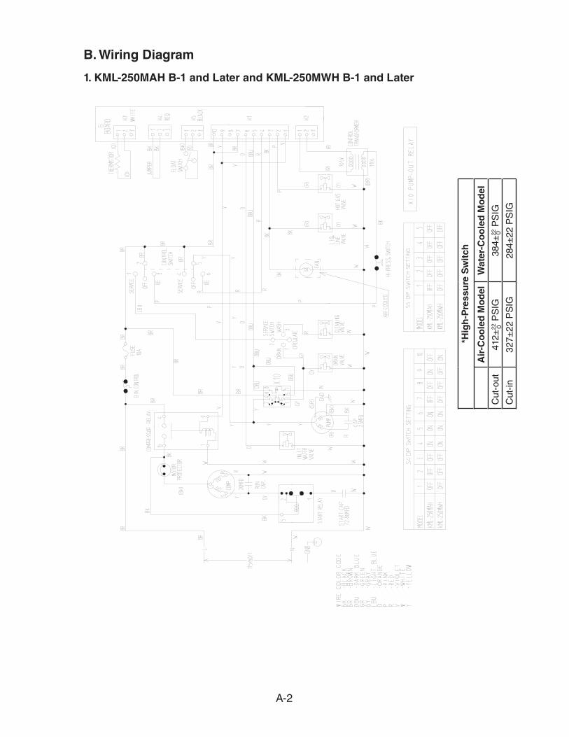
A-2
B. Wiring Diagram
1. KML-250MAH B-1 and Later and KML-250MWH B-1 and Later
*Hig
h-P
ress
ure
Sw
itch
Air
-Co
ole
d M
od
elW
ater
-Co
ole
d M
od
el
Cut
-out
412±
22 P
SIG
384±
22 P
SIG
Cut
-in
327±
22 P
SIG
284±
22 P
SIG
00


