1 HOT GAS FILTRATION USING SINTERED METAL FILTERS Dr. Kenneth L. Rubow Billy Huang Mike Wilson Edward Mahon Mott Corporation Presented at the 4 th China International Conference Shanghai, China November 2006
Transcript
1
HOT GAS FILTRATION USING SINTEREDMETAL FILTERS
Dr. Kenneth L. RubowBilly HuangMike Wilson
Edward MahonMott Corporation
Presented at the4th China International Conference
Shanghai, China
November 2006
2
ABSTRACT
Filtration systems utilizing sintered metal media have proven to be an effective, reliable and economicalchoice for gas/solids (particulate) separation in numerous industrial gas filtration applications in thechemical process, oil refining, petrochemical and power generation industries. Applications requireparticulate removal to protect downstream equipment, for product separation, for catalyst recycling, forcontaminate removal, or to meet environmental regulations. Today these processes are requiringseparation of increasingly finer particulate along with more reliable filter media. Filters fabricated fromsintered metal media offer unique performance characteristics for gas/solids separation in thesedemanding environments. These filters can provide particulate capture efficiencies of 99.9% or betterusing either surface or depth media. Operating temperature can be as high as 1000
oC, depending on
the selection of metal alloy. Along with the filtration efficiency consideration, equally important criteriainclude corrosion resistance, mechanical strength at service temperature, cake release (blowbackcleanability), and long on-stream service life. The design of particulate separation systems to meet thesecriteria is critical to achieving successful, cost effective operations.
Gas filtration is the process of removing solid particles from a gaseous fluid using a porous media with theultimate objective to achieve a pre-determined level of fluid purity. Sintered metal media combine manydifferent properties, ranging from its outstanding filtration and cleaning characteristics and its excellentchemical and thermal resistance to its mechanical strength. The two main dynamic modes of filtration,i.e., depth filtration and surface filtration, must be considered and exploited in the appropriate design andselection of optimal filter media. In the case of depth filtration, the particles are captured inside themedia, while in surface filtration they are retained, as the term explains, at the surface wheresubsequently a cake of particles is formed. The life of such filter media (filter operating life) depends onthe particulate characteristics (e.g., size, shape, composition) and the filter’s particulate holding capacity,corresponding pressure drop and ability to be cleaned, either on or off-line.
The benefits of using either sintered metal powder or sintered metal fiber filters are described in thispaper for industrial applications requiring semi-permanent filtration in especially demanding applicationsincluding corrosive environments at high temperatures and pressures. Filter operation and performanceare discussed for selected applications, including fluid catalytic cracking (FCC) and continuous catalyticreforming/regeneration (CCR) process operations.
INTRODUCTION
The chemical process industries must strive to meet ever more demanding economic and environmentalchallenges that result from market globalization, environmental regulations, rising costs, demands formore efficient processes, and changing workforce requirements. Products and processes involving solids(particulate) handling are ubiquitous in these industries, thereby requiring particle separation solutions.
Numerous types of industrial process equipment, employing different technologies for gas/solidsseparations, are available for the myriad of processes requiring gas/solids separation. These separationtechnologies include filtration (metal and ceramic elements, fabric bag houses), cyclones, electrostaticprecipitators and scrubbers. Each has its own degree of effectiveness and cost. In applications wherehigh removal efficiency is critical, filtration has no equal. The reason for this is simple. Compared to othermethods, filtration is the only one that provides a positive barrier between the process and the “solidsfree” stream whereby the particulate matter is removed from the gas stream through mechanicalseparation. Filtration can improve product purity, increase throughput capacity, eliminate effluentcontamination (minimizing or preventing air pollution), provide protection to valuable equipmentdownstream of the filter and/or allow for recycling of process catalysts.
Sintered porous metal filter media offers unique performance characteristics for gas/solids separation.Precision porous metal media, with its precise bubble point control, and excellent uniformity ofpermeability assures reliable filtration performance, effective blowback cleaning and long on-stream
3
service life. Furthermore, filtration systems, utilizing sintered metal media, have proven to be an effectiveand economical alternative to other separation equipment susceptible to pressure spikes, hightemperatures, and aggressive environments.
Advances in filtration technology and filter system designs, with their unique operating capabilities, haveresulted in the development of continuous processes to replace old batch process technology. Cost savingsinclude less hazardous waste for disposal and labor savings from new technology. Fully automated filtersystems can be integrated into plant process controls. Sintered metal filtration systems have provenperformance in the recovery of catalysts, products for chemical processing and pharmaceuticalsapplications, rock quarries, metal mining industry, power generating facilities, coal and coke handlingoperations, and many other applications.
SINTERED POROUS METAL FILTER MEDIA
Sintered porous metal media, fabricated from either metal powder or metal fiber, are widely used forindustrial gas and liquid filtration in various processes found in the chemical process, petrochemical,power generation and semiconductor industries where filtration is required to protect downstreamequipment, for process separation, or to meet environmental regulations. Filters with semi-permanentmedia are cost effective, since such units lend themselves to minimal downtime, closed and automaticoperation with minimal operator intervention, and infrequent maintenance. The proper selection of filtermedia with appropriate pore size, strength and corrosion resistance enables long-term filter operation withhigh efficiency particle retention.
Sintered porous metal media meets these criteria and offers high removal efficiency to meet tighteremission standards for today’s industrial applications. The development of specially designed andengineered sintered porous metal media with a stable porous matrix, precise bubble point specifications,close thickness tolerances, and uniformity of permeability assures reliable filtration performance, effectiveblowback cleaning and long on-stream service life.
The properties of metal filters, fabricated from various metal alloys, for gas filtration applications allow theuse in extreme conditions: high temperature, high pressure and corrosive atmospheres. The primarybenefits of sintered metal filters are: strength and fracture toughness, high pressure and temperaturecapabilities, high thermal shock resistance, corrosion resistance, cleanability, all-welded assembly, andlong service life.
Sintered metal media can be considered as semi-permanent media with an all welded construction. Anadvantage of metal filters is that they are welded to metal hardware to obtain strong sealed joints. Themedia can withstand pressure spikes with no evidence of media migration. The inherent toughness of themetal filters provides for continuous, back pulsed operation for extended periods. For high temperatureapplications, additional criteria such as creep-fatigue interactions and high temperature corrosionmechanisms need to be addressed. Filters with semi-permanent media are cost effective, since suchunits lend themselves to minimal downtime, closed and automatic operation with minimal operatorintervention, and infrequent maintenance.
Filter cartridges fabricated from sheet or tubes have an all welded construction. The filter media isdesigned and engineered with a stable porous matrix, precise bubble point specifications, close thicknesstolerances, and uniformity of permeability, which assure reliable filtration performance, effective backwashcleaning and long on-stream service life.
Sintered Metal Powder MediaSintered metal powder filter elements have been commercially available for more than 40 years. Theyare made from various alloy powders to meet corrosion and strength requirements.
4
Sintered metal powder media are manufactured by pressing pre-alloyed powder either into tubes or asporous sheet, followed by high temperature sintering. A scanning electron photomicrograph of typicalmedia is shown in Figure 1.
The combination of powder size, pressing, and sintering operations defines the pore size distribution,strength, and permeability of the porous media. Pore size of sintered metal media is determined usingASTM E-128. The media grade designation is equivalent to the mean flow pore, or average pore size ofthe filter. Sintered metal media are offered in grades 0.1, 0.2, 0.5, 1, 2, 5, 10, 20, 40 and 100. Thefiltration rating in gas ranges from 0.1 to 100 m absolute.
The sintered metal powder media are available in different alloys - including stainless steel 316L,Hastelloy
®B, C-22, C276, N and X; Inconel
®600, 625, and 690; Monel
®400; nickel 200; alloy 20 and
titanium - to handle wide-ranging corrosion and temperature environments.
Sintered metal powder media offer a temperature range of 750 to 1750°F depending on alloy material andatmospheric conditions (oxidizing or reducing). Temperature limitations of sintered porous metal in anoxidizing environment are not due to strength of material, but due to oxides that form at elevatedtemperatures. The specific void volume of the oxide is much greater than the parent metal, which resultsin plugging of the pores in the media. In a reducing or neutral atmosphere, temperature limitations aredue to strength of the material at elevated temperatures.
Figure 2. Photomicrograph of sintered metal fibermedia.
Sintered Fiber Metal MediaMetal fiber filter media consists of very thin (1.5 to 80 µm) metal filaments uniformly laid to form a three-dimensional non-woven structure sintered at the contact points. A scanning electron photomicrograph ofa typical sintered metal filter media is shown in Figure 2. These media are explicitly designed for eithersurface or depth filters. Either single or multi-layered construction are utilized with each layer comprisedof potentially different diameter fibers to achieve optimal performance, e.g., pressure drop, filtrationefficiency, particle loading capacity, and media strength. The multi-layered material has a graduateddesign, so the dirt holding capacity is much higher and consequently the life expectancy is longer. Thefinal filter rating is determined by the weight per used layer, the fiber composition of the layer and the
Figure 1. Photomicrograph of sinteredmetal powder metal media.
5
combination of several layers. The availability of a high porous structure (up to 85%) offers higherpermeability and hence a low pressure drop.
Fiber metal media have a higher porosity than the powder metal media, thereby resulting in lowerpressure drop. These fiber media are often manufactured from 316L stainless steel fibers, which aresuitable for a wide range of process operating conditions. For higher temperature or more corrosiveapplications, Inconel® 601 and Fecralloy® are used for high temperatures (up to 560°C and 1000°Crespectively) whereas Alloy HR can withstand temperatures up to 600°C and wet corrosive environments.
The proper selection of filter media with appropriate pore size, strength and corrosion resistance enableslong-term filter operation with high efficiency particle retention. The filtration rating in gas ranges from 0.1to 10 m absolute.
FILTRATION FUNDAMENTALS AND MEDIA DESIGN
Understanding of the fundamental processes of particle removal as a gas stream passes through a filteris critical to optimum selection of appropriate media and to successful filter design and operation. Forgases with low levels of particulate contamination, filtration by capturing the particles within the depth of aporous media is key to achieving high levels of particle efficiency. The structure of sintered metalprovides a tortuous path in which particles are captured. Continued particle capture can lead to formationof cake of deposited particles on the media surface, as particles are now captured on previouslydeposited particles, first by filling (blocking) the surface pores and subsequently collecting on the mediasurface. The life of such filters will depend on its dirt-holding capacity and the corresponding pressuredrop.
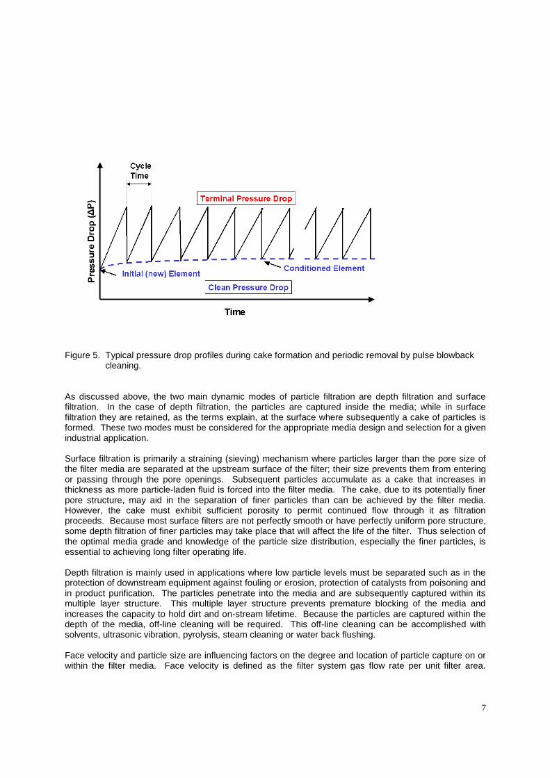
For gases with high dust loading, the operative filtration mechanism becomes cake filtration as the mediais specifically engineered to ensure surface filtration and the possibility of cake particulate removal viapulse blowback cleaning. A particle cake is developed on the surface of the filter media, as illustrated inFigure 3 and shown in Figure 4, that becomes the filtration layer and causes additional pressure drop.The pressure drop increases as the particle loading increases, as shown in Figure 5. Once a terminalpressure is reached during the filtration cycle, the filter element is blown back with a pulse of clean gas todislodge the filter cake. If the pore size in the filter media is chosen correctly, the pressure drop of themedia can be recovered to the initial pressure drop. However, if particles become lodged within theporous media during forward flow, and progressively load the media, the pressure drop may not becompletely recovered after the cleaning cycle. This increase in clean “recovery” pressure drop is shownin Figure 5. The optimal design application results in minimal increase in the clean (recovery) pressuredrop after a blowback cleaning cycle, and more importantly, ensures an equilibrium operating conditionafter an initial series of blowback cycles.
The effectiveness of the cleaning cycle and the pressure drop recovery is a critical function of theproperties of the cake and media pore size. The cake strength depends upon the dust particlemorphology and size distribution, electrostatic and chemical interactions, and cake moisture levels.
6
Figure 3. Particle loading during surface filtration and subsequent cake release during pulse blowback.
Figure 4. Photograph of cake release during pulse blowback.
7
Figure 5. Typical pressure drop profiles during cake formation and periodic removal by pulse blowbackcleaning.
As discussed above, the two main dynamic modes of particle filtration are depth filtration and surfacefiltration. In the case of depth filtration, the particles are captured inside the media; while in surfacefiltration they are retained, as the terms explain, at the surface where subsequently a cake of particles isformed. These two modes must be considered for the appropriate media design and selection for a givenindustrial application.
Surface filtration is primarily a straining (sieving) mechanism where particles larger than the pore size ofthe filter media are separated at the upstream surface of the filter; their size prevents them from enteringor passing through the pore openings. Subsequent particles accumulate as a cake that increases inthickness as more particle-laden fluid is forced into the filter media. The cake, due to its potentially finerpore structure, may aid in the separation of finer particles than can be achieved by the filter media.However, the cake must exhibit sufficient porosity to permit continued flow through it as filtrationproceeds. Because most surface filters are not perfectly smooth or have perfectly uniform pore structure,some depth filtration of finer particles may take place that will affect the life of the filter. Thus selection ofthe optimal media grade and knowledge of the particle size distribution, especially the finer particles, isessential to achieving long filter operating life.
Depth filtration is mainly used in applications where low particle levels must be separated such as in theprotection of downstream equipment against fouling or erosion, protection of catalysts from poisoning andin product purification. The particles penetrate into the media and are subsequently captured within itsmultiple layer structure. This multiple layer structure prevents premature blocking of the media andincreases the capacity to hold dirt and on-stream lifetime. Because the particles are captured within thedepth of the media, off-line cleaning will be required. This off-line cleaning can be accomplished withsolvents, ultrasonic vibration, pyrolysis, steam cleaning or water back flushing.
Face velocity and particle size are influencing factors on the degree and location of particle capture on orwithin the filter media. Face velocity is defined as the filter system gas flow rate per unit filter area.
8
Optimal design of filtration systems requires proper selection of face velocity to achieve long on-streamlife operation and prevent particle intrusion into the media. A filter design, which exceeds the maximumface velocity, can lead to premature blinding of the filter element(s). Gas filtration performance isenhanced when a surface or cake is formed providing additional long-term filtration. Optimal facevelocities typically are in the range of 6-8 ft/min (3-4 cm/s) to ensure adequate cake removal during pulseblowback cleaning cycles.
FILTER SYSTEM DESIGN AND OPERATION
Gas/solids filtration systems for chemical process applications operate in one of two basic processdesigns, namely as continuous process filters or final (or trap filters). Both designs are well suited forsintered porous metal elements. In their typical operating mode, both designs function in a similarfashion, gas flows through the media whereas particulates are retained and accumulate on it. Thefundamental difference between the two is the frequency and method of solids removal and elementregeneration. The decision on which type of filter to employ depends on individual process parameters,primarily the solids loading in the feedstream.
Final or trap filters are used on basically clean streams where the objective is either polishing orprotection of downstream processes and equipment. These filters are not intended for in-situ cleaningand solids removal requires disassembly. Elements are normally cleaned externally using chemical orultrasonic methods. The interval between cleaning varies with the solids load and the feed gas.
A continuous process filter is ideally suited for heavily particulate laden streams or in processescontaining hazardous materials. Again, the cleaning or blowback interval depends on the solids loading.Typical periods range from 1 to 2 minutes up to many hours. The blowback cycle can be initiated eithermanually or automatically based on time lapse or differential pressure. Figure 5 illustrates two sequentialseries of filter cleaning cycles during the initial and subsequent equilibrium portion of the filter operatinglife.
Mott Corporation offers two different continuous process filter designs, the HyPulse GSP (Gas-Solids-Plenum) and the HyPulse GSV (Gas-Solids-Venturi). Both systems are well suited for automated processcontrol and include in-situ cleaning for the elements but in somewhat different ways.
Particulate loading on the filter elements is similar for both filter configurations. During the filter cycle, thegas/solids mixture enters the unit and flows toward the outside of the sintered metal filter elements, wheresolids are retained. The “cleaned” gas passes through the element wall, into the plenum chamber, and isdischarged from the filter system.
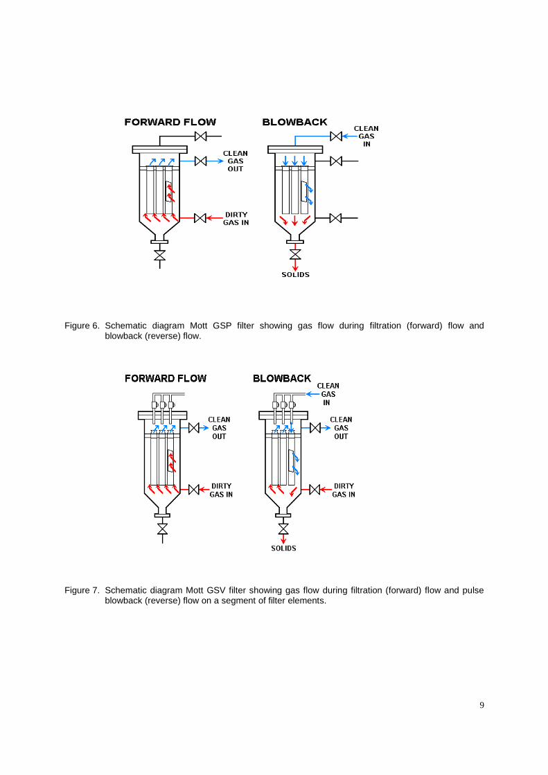
The forward flow (filtration cycle) and reverse flow (blowback cleaning) for the HyPulse GSP filter systemis illustrated in Figure 6. Upon reaching a given differential pressure or cycle time, the feed isdiscontinued and the backflow cycle begins. The filter is isolated and gas enters the gas inlet. Reverseflowing through the plenum chamber and elements discharges the cake from the element wall.
The forward flow (filtration cycle) and reverse flow (blowback cleaning) for the HyPulse GSV filter systemis shown in Figure 7. This system delivers high throughput with minimum backpulse gas requirements.Sintered metal cartridge filters are manifolded together and backpulsed sequentially while the unitremains on-line. When a predetermined differential pressure or cycle time is realized, the elements arebackpulsed to remove the cake. While on-line, a burst of high pressure gas enters the nozzle manifoldthrough the upstream solenoid valves. The blowback gas exits the nozzles and enters the venturisentraining the gas from the plenum chamber. The resulting gas flow creates a high-energy backpulse onthe elements that lifts off the filter cake. The cake falls into a discharge hopper and is removed. Thereverse pulse of blowback gas typically lasts from 2 to 3 sec. Only a portion of the elements are pulsecleaned at any one time while the remainder continue to operate in the filtration mode, thereby ensuringcontinuous flow of the process gas stream.
9
Figure 6. Schematic diagram Mott GSP filter showing gas flow during filtration (forward) flow andblowback (reverse) flow.
Figure 7. Schematic diagram Mott GSV filter showing gas flow during filtration (forward) flow and pulseblowback (reverse) flow on a segment of filter elements.
10
Figure 8. Cutaway illustration of GSV filter system as installed on catalyst hopper.
Figure 9. Tubesheet bundle frame assembly.
11
A cutaway illustration of a GSV filter system, as installed on catalyst hopper, is presented in Figure 8.The figure shows the flanged filter top head bonnet assembly, accumulator tank (for the blowback gas)and backpulse valves. Figure 9 illustrates a tubesheet bundle frame assembly. The filter is designedsuch that the filter can be easily disassembled for service and/or replacement of filter elements.
Media Selection and System Performance
Extended testing provides data relevant to the trends of performance efficiency and indicated desirablerates of operation. Recovery pressure drop after blowback can be determined to ensure long-termtrends. Optimum operating conditions are criteria for long operating life.
Proper particle loading and pulse blowback cleaning are critically important to the selection of theoptimum operating system conditions. For example, a study with flyash particles was conducted todetermine the appropriate operating conditions. The filter housing was fabricated from transparent acrylicplastic, to allow direct visual observation of filtration and blowback, and accommodated a maximum of 6filter elements with an associated verturis, solenoid valve manifold, and blowback control system. Figure4 shows the cake release of the flyash at the inception of the pulse blowback cycle. Equilibrium recoverydifferential pressure, as graphically shown in Figure 5, typical occur within 25 blowback cycles, but aredependent on media selection, face velocity and particle characteristics (namely size, shape andcomposition).
COMMERCIAL APPLICATIONS: CASE STUDIES
Gas filters are typically used on catalyst hoppers and duct vents employed in the fluid catalytic cracking(FCC) and continuous catalytic reforming/regeneration (CCR) process operations used in crude oilrefining and petrochemical industries. Process flow schemes for typical operations are shown in Figures10 and 11. The filters efficiently remove catalyst particles from the vent gas streams, thereby minimizingparticulate air pollutants while allowing for these materials to be either reused or deposed in anenvironmental appropriated manner. Sintered metal filters are ideal for these applications, as the metallicmedia are well suited to provide long-term life. These filters offer lower capital cost for the filter system,lower installed cost, and lower annual operating costs, while providing high levels of particle removalefficiency.
Figure 10 shows a process flow scheme for a typical FCC process operation at a crude oil refinery. Thereare typically three types of catalyst storage hoppers in FCC process, namely: “fresh”, “equilibrium” and“spent” catalyst storage hoppers. Fresh catalyst storage hoppers are for storage of fresh catalyst at theplant site. Equilibrium catalyst storage hoppers are used for in-process storage as the catalyst istransferred between the reactor and regenerator. The spent catalyst storage hoppers are for temporarystorage prior to off-site disposal of spent catalyst.
Dust control filters are typical required and installed on these catalyst hoppers for three reasons. Thepneumatic transfer of catalyst creates dust during the transfer process. Dust must be controlled tominimize atmospheric emissions per governmental regulations. In-place recovery and reuse of costlycatalyst during the unload/fill/transfer operations reduces operating costs.
A typical catalyst hopper, with an associated dust filter mounted on the top, is shown in Figure 12. Thesehoppers typical have a diameter of 8 to 17 ft (2.4 to 5.2 m) and height of 35 to 65 ft (10.7 to 20 m), with aresulting storage capacity of 50 to 270 tons (45 to 250 metric tons). Figure 8 shows in greater detail aGSV filter assembly mounted on top of catalyst hopper. The typical filter is 24 to 48 inch (0.60 to 1.20 m)outside diameter.
12
Figure 10. Process flow scheme of typical FCC process operation showing the location of 3 catalysthoppers and filters (F1, F2 and F3).
Figure 11. Process flow scheme of typical CCR process operation showing the location of 2 filters (F1 andF2).
13
Figure 12. GSV filter system mounted on top of catalyst hopper.
Typical operating conditions of the catalyst hoppers are as follows. Catalyst is moved in and out ofstorage hoppers by pneumatic transfer using compressed gas. This gas is constantly vented from the topof each hopper during catalyst transfer operations. The vent hopper gas must be filtered for dustsuppression. The catalyst dust particles in the vent gas can range in size from 1 to 100 m in diameter.The hopper vent gas operating pressures range from partial vacuum to 25 psig (1.7 bar). The operatingtemperatures range from 60 °F to 650 °F (15 °C to 340 °C). The required filtration efficiency is usually99% solids removal or a dust emissions concentration level less than 50 mg/Nm3.
Porous metal media is robust and is very well suited for catalyst hopper vent filter applications as thefilters must be capable of operating over a very wide range of flow, temperature and pressure conditions.Many of these applications are ideally suited to 316L stainless steel media, which can handle servicetemperatures up to 750° to 1000° F (400 °C to 540 °C). Filters are capable of ensuring that the particleemission standards, which may be as low as 30 to 50 mg/Nm
3, can be met.
One primary function of the filter in CCR processes is to prevent fine catalyst particle from re-entering thereactor where they can deposits on the inner reactor surfaces, thereby adversely affecting the reactionrate. These fines are generated by attrition of the original catalyst particles. The operating pressures insome systems range from 170 to 350 psig (12 to 25 kg/cm
2) while in others processes, the pressure can
be as low as 50 psig (3.5 kg/cm2). The operating temperatures typically range from 210 °F to 400 °F (100
°C to 200 °C).
SUMMARY
Sintered metal media provides an effective means of filtering to remove particulate whether they areimpurities, valuable by-product, or catalyst within a chemical process stream. Sintered metal media issemi-permanent and is well suited for dust removal and gas treatment, particularly where pressure
14
spikes, high temperatures, corrosive atmospheres, hot gasses and sparks are present. Filtration systemsutilizing sintered metal media have been used successfully in place of bag houses, cyclones, electrostaticprecipitators and scrubbers.
Filter operating conditions affect its useful life and impact the efficiency of blowback solids removal.Media grade selection coupled with particle characteristics, and filter design operating flowrate, areimportant parameters to ensure optimal filter media operating life. Sintered metal filters should beoperated within the design parameters to prevent premature blinding of the media due to fluctuations inprocess operations. The cake becomes the filter media and the porous media acts as a septum to retainthe filter cake. Filter cakes can be effectively removed via pulse blowback cleaning from the filterelements and removed as bulk powders from the bottom of the filter housing or fall directly into thecatalyst hopper.
Both plenum blowback and venturi pulse blowback process systems are effective and can be designed toaccommodate a wide range of applications and performance requirements. Recovery pressureequilibrium depends on both filter rating and face velocity. Extended testing provided data relevant to thetrends of performance efficiency and indicated desirable rates of operation. Recovery pressure drop afterblowback was examined for long-term trends at different flow velocities. Optimum operating conditionswere determined for long operating life.
__________Hastelloy is a registered trademark of Hayes International, Inc.Inconel and Monel are registered trademarks of Special Metals Corporation.Fecralloy is a registered trademark of UKEA, UK.