170
HOUSING DEVELOPMENT Halmstad, Sweden Callén Gil, Ana-Cruz Construction engineering

HOUSING DEVELOPMENT
Halmstad, Sweden
Callén Gil, Ana-Cruz
Construction engineering
Housing development Ana Cruz Callén GilHalmstad, Sweden
2
Table of contents
1. Personal information. 41.1 Project author. • 5
1.2 Project supervisor. • 5
2. Data and project schedule. 62.1 Building precedents. • 7
2.2 Description of the area. Site location. • 7
2.3 Abbreviated project description. • 9
3. Design 123.1 Room height 1• 3
3.2 The design of dwellings 1• 3
3.3 Climate zone 1• 3
4. Technical description. 184.1 Conditioning of the area. 1• 7
4.2 Foundation. 1• 9
4.3 Structure. 2• 2
4.4 Walls 2• 4
4.5 Floors. 2• 8
4.6 Roof. 2• 9
4.7 Installations. 3• 0
4.8 Carpentry. 3• 1
4.9 Salubrity installations 3• 3
4.10 Plumbing installations. 3• 4
4.11 Hot and cold water 3• 4
4.12 Heating. 3• 5
4.13 Electrical installations. 3• 6
4.14 Isover 3• 7
4.15 Floors 3• 8

Housing development Ana Cruz Callén GilHalmstad, Sweden
3
5. Protection against fi re 405.1 Laws and regulations 4• 1
5.2 Regulations. 4• 1
5.3 Safety In Case Of Fire. 4• 1
6. Health and Safety Study 546.1 Object of the Study of Health and Safety. 5• 5
6.2 Conditions of the surroundings. 5• 7
6.3 Site preparation. 5• 7
6.4 Provisional facilities at work. 5• 9
6.5 Demolition. 6• 6
6.6 Movements of Lands 6• 8
6.7 Structure 7• 4
6.8 Permanent facilities 7• 9
6.9 Auxiliary equipment 8• 4
6.10 Machinery in general 8• 7
6.11 Appendix 8• 8
7. Emergency action plan 907.1 Scope a plan 9• 1
7.2 Emergency plan coordinators 9• 1
7.3 Elements of the plan 9• 1
8. Gantt chart 96
9. Budget 100
10. Pictures 120
11. Drawings 124

4
Personal information
Housing development Ana Cruz Callén GilHalmstad, Sweden
5
Personal information.1.
Project author.1.1
Ana-Cruz Callén Gil, student of Construction Engineering in “Escuela Universitaria Politéc-
nica de La Almunia de Doña Godina” in Zaragoza, Spain.
Project supervisor.1.2
Åke Spångberg, teacher of Civil engineering in the School of Business and Engineering at
Construction Engineering Programme at Halmstad University.

6
Data and project
schedule

Housing development Ana Cruz Callén GilHalmstad, Sweden
7
Data and project schedule.2.
Building precedents.2.1
Halmstad was founded close to the Nissan river in 1307. In 1320’s the town moved to the
present day town centre.
HALMSTAD
Halmstad is an industrial and recreational city with
a port. It is a quiet city at the mouth of Nissan in
the province of Halland. As we can see on the map,
Halmstad is on the Swedish west coast.
All areas around the river have always been impor-
tant places for trade. From the 19th century all the
whole area has been full of industries. However, a few
years ago this area started to change and nowadays
there are plans for making this zone more attractive
to inhabitants and tourists.
As widely as possible all industries around this area
will be reallocated. This is a main reason why the city
is growing in this area, therefore I decided to build a residential zone; a project which
will give more life to the actual industry zone in Halmstad. Without this project, this area
will continue to remain unused and quiet.
Description of the area. Site location.2.2
The plot where I am going to construct is close to the river Nissan, not so far from the
city centre. The picture shows the exact position.
Housing development Ana Cruz Callén GilHalmstad, Sweden
8
The site is situated in Stationsgatan near the Nissan River (Halmstad, Sweden). The site
has a regular shape with almost fl at surface.
The plot has a surface of 15.538m2. The undeveloped plot at present is empty. The only
building is a one-storey building with a sloped roof, owned by a local electrical company.
The building is not in use and it is going to be removed.
Running through the plot are old railroad tracks where trains formerly ran. However the
new railways runs to the east side of the plot.
Surrounding building2.2.1
Styrmansgatan
Sta
tions
g ata
n
Stuvaregatan
Rive
r Nis
san
plot
1
3
2
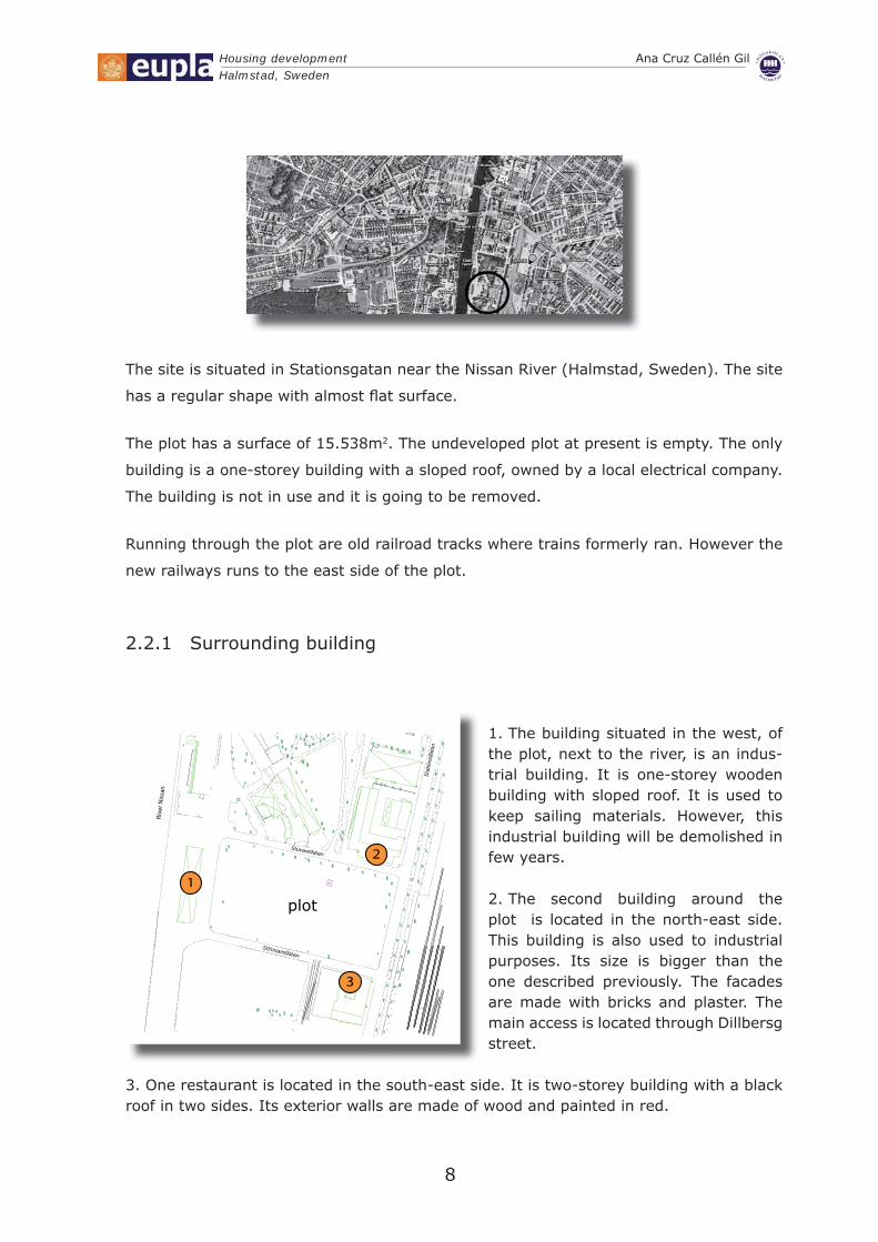
The building situated in the west, of 1. the plot, next to the river, is an indus-trial building. It is one-storey wooden building with sloped roof. It is used to keep sailing materials. However, this industrial building will be demolished in few years.
The second building around the 2. plot is located in the north-east side. This building is also used to industrial purposes. Its size is bigger than the one described previously. The facades are made with bricks and plaster. The main access is located through Dillbersg street.
One restaurant is located in the south-east side. It is two-storey building with a black 3. roof in two sides. Its exterior walls are made of wood and painted in red.

Housing development Ana Cruz Callén GilHalmstad, Sweden
9
The rest of the plot is surrounded by green areas.
Abbreviated project description.2.3
The project consists in nine single-family detached houses with a residential activity
building. This project is designed to suit the inhabitants who live in Halmstad. It includes
green areas to walk, playing areas and gardens. However, for many months the weather
in Halmstad is relatively cold, therefore, the project includes a common building where
residents can play sports, relax, meet even sunbathe. This will enhance the status of the
area.
My work pushes towards a form of architecture with less emphasis on ornament and a
greater emphasis on form, function, materials, clarity and quality. All homes in the plot
are designed to cater for a more relaxed mode of family living. These dwellings fi t with a
modern lifestyle, with the main points being comfort and with a balance between private
and communal space within the home.
Residential activity building2.3.1
This two-storey building has two separate structures which are linked by a walkway
on second fl oor level. Inside of the biggest structure, a double-height swimming pool
dominates.
This building retains an emphasis based on pure geometry and clear lines and blends into
the surrounding.
In addition to the previous description, the project has been designed in accordance
with the present building regulations of Halmstad, Sweden. In the design I took into
account requirements and comfort. Style and function come together in these buildings
designed for those looking for tranquillity and comfort. Furthermore, disabled people
absolutely can use all facilities because the building complies with the minimum acces-
sibility standards.
The common building is in the north-east zone of the plot. This position makes to keep
out noise of residential area because the trains run to the east side of the plot, in such a
way that future residential houses do not endure bother noise when trains run.
There are houses and a green area in front of the building which faces southwest.
Housing development Ana Cruz Callén GilHalmstad, Sweden
10
The ground fl oor is divided into two parts; relax area and multipurpose room. They are
not communicated between each other.
The multipurpose room is 102m2. In this room there are two toilets, one of them is
adapted to disabled people. Inside of the multipurpose room there are tables, chairs and
couches.
When you go inside of relax area you can fi nd the lobby and the access to the changing
rooms. They are connected to the swimming pool, the jacuzzi with capacity for 6 people
and the cold water pool. In the same fl oor, furthermore, there is a boiler room which
heats the water of all facilities. Finally, there is a storage room for all kinds of swimming
tools.
The lobby has an access to the fi rst fl oor, the lift or stairs can be used to reach the
training area. It includes training machines and tools to practice exercise. In the fi rst
fl oor, moreover, there is a vapour bath, a sauna and showers with different temperatures
and intensities. It is also possible to go up from the stairs which are next to the swim-
ming pool.
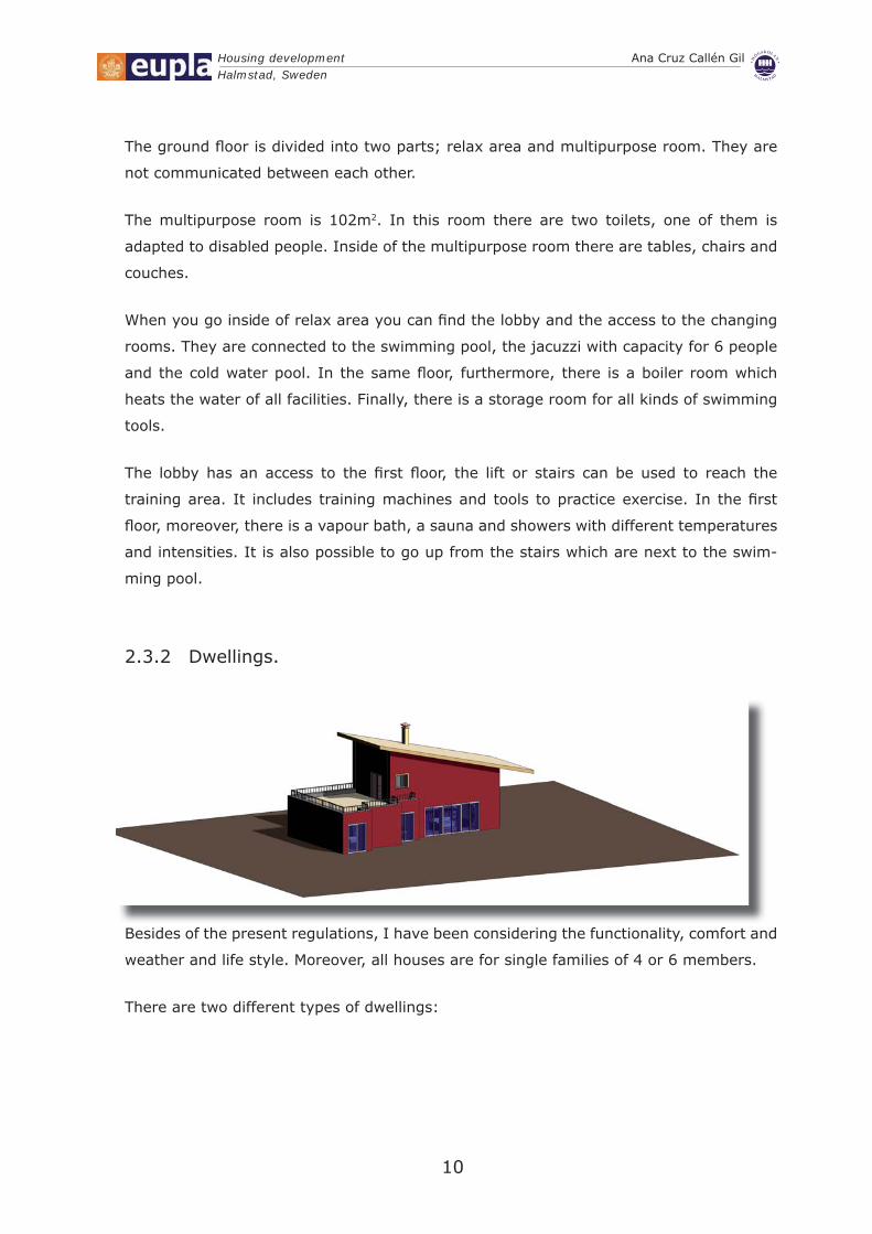
Dwellings.2.3.2
Besides of the present regulations, I have been considering the functionality, comfort and
weather and life style. Moreover, all houses are for single families of 4 or 6 members.
There are two different types of dwellings:
Housing development Ana Cruz Callén GilHalmstad, Sweden
11
Type 1: In the north side there are four dwellings with the same design. The houses
have two storeys. On the ground fl oor, there are a living room, kitchen, two bathrooms,
two bedrooms and a laundry room. On the fi rst fl oor there are one more bedroom, a
bathroom and a study room. The picture also shows big windows in the living room. The
bedroom located in the fi rst fl oor are connected with a terrace and one bathroom.
Type 2: In the south part of the plot there are fi ve dwellings with different design
comparing to the ones described previously. Those houses are bigger than type 1. This
kind of dwellings have four rooms, three of them are located in the ground fl oor. In the
same level there is also a kitchen, one living room, a laundry, a pantry, one toilet and two
bathrooms. In the upper level there is one more bathroom and a terrace.
Exterior areas.2.3.3
For gardens design and green roofs the current vegetation of Sweden will be used. In this
plot will be planted mainly pines and beeches.
In the exterior it will be also placed outdoor benches in wood and a children playground
in the middle of the plot.

12
Design

Housing development Ana Cruz Callén GilHalmstad, Sweden
13
Design3.
The design is one of the most important things in the project. A good design will made
buildings more comfortable. Swedish Building Regulations (BBR) have been followed in
this section.
Room height3.1
Following the regulation section 3, height of habitable rooms and workrooms are not less
than 2.40 meters. In single family houses, the height of the rooms in the attic and base-
ment is more than 2.30 meters.
The design of dwellings3.2
Following the current regulations , the houses designed in this project have at least:
A room with fi tting and equipment for personal hygiene,•
A room for everyday social contact,•
A room for sleep and rest,•
A room, or a separate part of room, with fi tting and equipment for cooking and •
storage food,
A dinning space in or near the kitchen,•
A space for homework,•
A place near the entrance with space for outdoor clothes.•
Space for storage.•
These dwellings have more than one storey. In the entrance storey there is a bathroom
for disable people sitting in a wheelchair.
Climate zone3.3
Before deciding the materials used in this project, it has been necessary to consider the
climate zone where Halmstad is.

Housing development Ana Cruz Callén GilHalmstad, Sweden
14
Sweden is divided into three climatic zones. Halmstad is located in the Halland area which
is in the climate zone III. It means that houses will be designed to a specifi c energy
consumption, electric power for heating and average heating transfer coeffi cient for the
structural elements that enclose the building .
In the following table show the maximum values used in houses that have new heating
method such as district heating.
Climate zone III
Specifi c energy 55
Installed capacity for heating 4,5
U m 0,40
The materials used in the project are in accordance with data described above.
Access to buildings: The entrances have been designed to be accessible for disabled
people.
Roads in the exterior areas can be used by physically disabled people. People with visual
and/or hearing impairment and people who become easily confused have suffi cient space
for handling wheelchair.
Residential activity building is provided with bathrooms for people sitting in a
wheelchair.


16
Technical description
Housing development Ana Cruz Callén GilHalmstad, Sweden
17
Technical description.4.
First the residential activity building will be constructed, when it will be nearly fi nished,
dwellings will be started to build. Finally trees, gardens and fl owers will be planted.
Conditioning of the area.4.1
The building site is accessible by all type of machines and equips that are going to be
used in the construction. There is enough space for keeping part of the material which
will be used in the buildings
Demolition.4.1.1
We have to proceed to the demolition of the small building that nowadays exist in our
plot.
The demolition of this building will be done in two phases: The fi rst phase will be a
manual demolition, to recover and to be able to re-use most of cables that now exist in
the current building. This phase is very important, as recycling, we can generate less
waste of materials.
The second phase of demolition, it will be done by suitable machinery, and with these
machines we will knock down all that we could not recover and re-use.
Explanations4.1.2
We will make the cleaning of the land, and removal of the topsoil layer. Later, the corre-
sponding land transport will be made with machine trucks loaded until the closest garbage
deposit.
Housing development Ana Cruz Callén GilHalmstad, Sweden
18
Building layout.4.1.3
Once the place is clean, it will be become to lay the zones to excavate out, letting
witnesses of this topographic layout to be able to make the pertinent verifi cations at any
time.
The area will be excavated by mechanical methods. The topographic layout of the walls
and foundation will be hand made, letting witnesses of this layout to be able to make the
pertinent verifi cations in any time, remaining always clean of rubbish and ground.
Finishing the layout part, the part of excavation of foundation of the swimming pool and
the laying of footings of the building will be made.
Layout techniques are described in the following paragraphs. The following are the used
layout tools and materials:
A string line is used to distinguish the dimensions of the building layout.•
A sledgehammer is used to sink corner stakes or batter boards and posts.•
A posthole auger is used to dig the holes required to set posts properly in some •
soils.
A handsaw is used to cut batter boards and posts.•
An ax or a hatchet is used to sharpen batter-board posts and stakes.•
A hammer is used for building batter boards.•
A chalk line is used to deposit chalk on the surface in order to make a straight •
guideline.
A 30-meter tape is used for measuring diagonally •
Tracing tape is used for laying out excavation or foundation lines. The tape is made •
of cotton cloth approximately 1 inch wide. It usually comes in a 200 foot length.
A carpenter’s level is used to level a surface and to sight level lines. It may be used •
directly on the surface or with a straightedge.
A line level has a spirit bubble to show levelness. The level is hung from a taut •
line. It gives the greatest accuracy when it is placed halfway between the points to
be levelled.
An automatic level measures approximate differences in elevation and can estab-•
lish grades over limited distances.
A plumbing bob is used to locate the corners of the building dimensions.•
A framing square is used to check the squareness of lines•
Housing development Ana Cruz Callén GilHalmstad, Sweden
19
Construction of drains4.1.4
The fi rst necessity in the construction of drains is a ground plan of the premises, showing
the position of the whole sanitary appliances from which the waste-water has to be
conveyed away. It is also important to show the position of the sewer or cesspool with
which they have to be connected.
As the excavation proceeds, the sides of the trench will be supported by strong
timbering.
The drain will be made by mechanical method, being adopted the opportune measures to
avoid as much our damages as the public way, following at any moment the fulfi lments
of the regulation.
The leftover grounds of the drain will be transported with trucks to the nearest waste
treatment plant.
Foundation.4.2
The building foundation is the part of a structure which is placed below the surface of the
ground and which transmits the upper structure load to the underlying soil.
It is the part of a structural system that supports and anchors the upper part of the
structure in the building.
Foundation is the most important part of a building. Building activity starts with the
formation of foundation. Main activities of building foundation are:
Distribute building load to soil beneath•
Distribute the load uniformly•
Grapnel the structure to the ground to resist movement due to lateral force•
Housing development Ana Cruz Callén GilHalmstad, Sweden
20
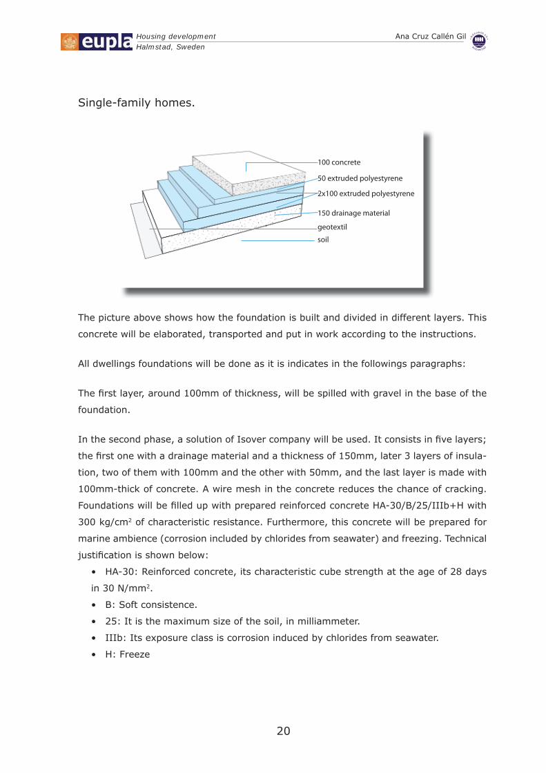
Single-family homes.
100 concrete
50 extruded polyestyrene
2x100 extruded polyestyrene
150 drainage material
geotextil
soil
The picture above shows how the foundation is built and divided in different layers. This
concrete will be elaborated, transported and put in work according to the instructions.
All dwellings foundations will be done as it is indicates in the followings paragraphs:
The fi rst layer, around 100mm of thickness, will be spilled with gravel in the base of the
foundation.
In the second phase, a solution of Isover company will be used. It consists in fi ve layers;
the fi rst one with a drainage material and a thickness of 150mm, later 3 layers of insula-
tion, two of them with 100mm and the other with 50mm, and the last layer is made with
100mm-thick of concrete. A wire mesh in the concrete reduces the chance of cracking.
Foundations will be fi lled up with prepared reinforced concrete HA-30/B/25/IIIb+H with
300 kg/cm2 of characteristic resistance. Furthermore, this concrete will be prepared for
marine ambience (corrosion included by chlorides from seawater) and freezing. Technical
justifi cation is shown below:
HA-30: Reinforced concrete, its characteristic cube strength at the age of 28 days •
in 30 N/mm2.
B: Soft consistence.•
25: It is the maximum size of the soil, in milliammeter.•
IIIb: Its exposure class is corrosion induced by chlorides from seawater.•
H: Freeze•

Housing development Ana Cruz Callén GilHalmstad, Sweden
21
Residential activity building:
Isolated column footings are used to support single columns. Each individual isolated
footing provides support for each individual column, they act as a base for a column.
They transfer the superimposed structural load to a wide range soil. All columns in this
project are square. Furthermore they are made with reinforced cement concrete.
For this building there are also combined footings. It has been constructed for avoiding
when a column lies very close to the property line and preventing overlapping of footings
when columns are very adjacent. They are rectangular in fi rst instance.
In case of column subjected to heavy loading and bending this type of column footing
provides a superior solution in shallow foundation. Made with reinforcement and concrete
this type of footing is high on strength and bending. The footing is reinforced with rebar.
This type of footing is capable of transmitting massive loads with a reduced footing
depth.
Steps of insulated footing:
Soil excavation: To set a footing, the fi rst step is to excavate the soil of the respec-•
tive area. At fi rst the area should be located.
Levelling & dressing of soil surface: After excavation, the most important step is to •
level the soil surface. The load of the construction should be vertical, for this, levelling
and dressing is required. Otherwise the construction might be subjected to tilting to
one side.
Giving a cement concrete layer on it: This layer has 10cm of thickness. It provides •
a smooth, uniform and strong surface for reinforcement frame.
Shuttering: It mens the solid boundary around the concrete. Wooden shuttering •
will be used for this project.
Placing of reinforcement •
Pour concrete•
Curing: This is one of essential requirements of the concrete process. The strength •
of concrete increases more rapidly in the fi rst few days after setting and afterwords the
rate of increase in strength goes on retarding. The period curing should be continued
depends upon atmospheric conditions such as temperature, humidity and wind velocity.
Correct curing also increases of concrete to abrasion and reduces shrinkages.
Removal of form•
Backfi lling of excavated area•
Housing development Ana Cruz Callén GilHalmstad, Sweden
22
Structure.4.3
Single-family houses.
Timber frames: As its name implies, timber frame construction is a method of building,
which relies on a timber frame as a means of structural support.
Timber frame construction is based on factory-made structural elements. The timber
framed wall panels carry the loads on the building to the foundations whilst the outer clad-
ding provides decoration and weather protection. The outer cladding is made of brick.
Factory production of the timber frame panels ensures that they are accurately manufac-
tured to precise tolerances in a controlled environment.
Timber frame wall panels are made up of softwood vertical studs and horizontal rails
with a wood-based panel sheathing and a plasterboard lining. The studs carry vertical
loads through the structure and transfer them to the foundations. The sheathing provides
resistance to lateral wind loads (known as racking resistance). Thermal insulation incor-
porated in the spaces between the studs of external walls and protective membrane
materials are required. The timber frame panels are quickly erected on site.
Timber frame is the fastest growing method of construction in Sweden today, and there
are many good reasons for this.
Timber frame delivers high build quality, a faster and much more effi cient construction
process. Furthermore it is a renewable construction material and the softwoods used in
timber frame are sourced from environmentally sustainable Swedish forests.
The external wooden frame walls are also put together on site. The building envelope is
highly insulated. Wood trusses will be used in the upper level to support the roof. Double
cantilever has been chosen for sloped roofs.

Housing development Ana Cruz Callén GilHalmstad, Sweden
23
Residential activity building:
The load bearing structure is made of precast concrete. These columns are used to
support beams in the precast concrete structural system. They are designed to multilevel
components. Furthermore, they have been made with conventional reinforcing bars.
They are cast in a horizontal position and rotated to their fi nal position at the jobsite by
the erection crew.
Size and shape used:
Square 40x40cm•
Circle: diameter 50cm.•
Beams1.
Beams are horizontal components which support hollow-core slabs. They are considered
structural components. For this project, rectangular beams have been chosen.
The beams used during the engineering design are reinforced with conventional rein-
forcing bars.
Since beams are cast upright, the bottom part, all sides in the house, and ledges are
cast against a form and they will be provided with an “as cast” fi nishing in results in a
smooth, hard fi nish. The top is intentionally roughened to create a bond with cast-in-
place concrete that it will be putted on top of it. It resistance is 348kg/m2.
Hollow-Core slabs2.
Hollow-core slabs are used for fl oor and roof deck components.
Dimensions are the followings: The slabs are 120cm wide with 20cm thicknesses with
5cm of reinforced topping concrete.
Finishes: Form side (bottom) is smooth as cast and remains that way in the fi nished
construction. The top side is slightly rough to receive a layer of cast in-place concrete.
Stairs3.
Precast concrete stairs will be used. They are fabricated as shorter components consisting
of only the tread/stair section supported by separate landing components.

Housing development Ana Cruz Callén GilHalmstad, Sweden
24
These modules of stairs provide fast erection and durable access in the residential activity
building.
Abrasive nosing pieces are cast into the treads to create a non-slip surface.
Finishes: The bottom will be trowelled to the desired degree of smoothness and it will
remain exposed to view in the fi nal construction.
Walls4.4
Outer closings. 4.4.1
Single-family houses.
Today’s modern housing needs to provide much more than basic shelter from the elements,
it must offer high standards of quality and safety throughout. Just as high standards
of energy effi ciency have now become the norm, families today require a comfortable
thermal environment all year round, and excellent acoustic protection from both inter-
nally and externally generated noise.
Equally important are issues such as fi re protection and the longevity of the property
and, of course the quality of the internal air within the building.
To address these challenges, I have chosen the following materials:
The facades will be composed by a solution made with
13mm of plasterboard, 120mm timber stud with insula-
tion Isover UNI-Skiva 33 between, a vapour control and
airtightness membrane “Isover VARIO DUPLEX”, another
170mm of timber stud with the same insulation between,
13mm of plasterboard, 80mm of insulation Isover Fasad-
skiva 31 and one clear cavity. After this, the external
fi nish will be made with brick solution of 12mm of thick-
ness. The total thickness of the wall is 536mm.
Housing development Ana Cruz Callén GilHalmstad, Sweden
25
Mineral wool: Isover insulation does not absorb water, therefore does not sustain vermin,
or promote the growth of mould, fungi or bacteria.
Timber: There is a long tradition of woodworking in the Swedish industry, ensuring quality
in production. Sweden is a big timber exporter, approximately 70% of its total produc-
tion go to other countries. The sawn timber is mainly softwood, Spruce/whitewood (Picea
abies), pine/redwood (Pinus sylvestris) and just a few per cent is hardwood. Normally
softwood is used for most structural timber, as it is easily worked due to its softness and
straightness of grain.
I have chosen the pine as structure to all dwellings mindful some qualities as density
(3,9 kg/m3), thermal conductivity (0.14 W / m • °C), coeffi cient of thermal expansion
(34 x 10-6). Furthermore, The pine is fi brous and elastic, making it strong in tension and
compression. Its maximum use temperature is 200 °C.
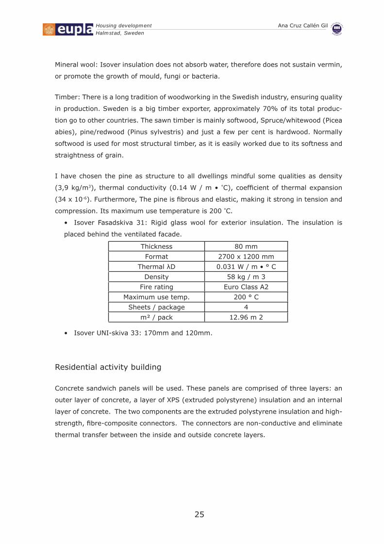
Isover Fasadskiva 31: Rigid glass wool for exterior insulation. The insulation is •
placed behind the ventilated facade.
Thickness 80 mm
Format 2700 x 1200 mm
Thermal λD 0.031 W / m • ° C
Density 58 kg / m 3
Fire rating Euro Class A2
Maximum use temp. 200 ° C
Sheets / package 4
m² / pack 12.96 m 2
Isover UNI-skiva 33: 170mm and 120mm.•
Residential activity building
Concrete sandwich panels will be used. These panels are comprised of three layers: an
outer layer of concrete, a layer of XPS (extruded polystyrene) insulation and an internal
layer of concrete. The two components are the extruded polystyrene insulation and high-
strength, fi bre-composite connectors. The connectors are non-conductive and eliminate
thermal transfer between the inside and outside concrete layers.
Housing development Ana Cruz Callén GilHalmstad, Sweden
26
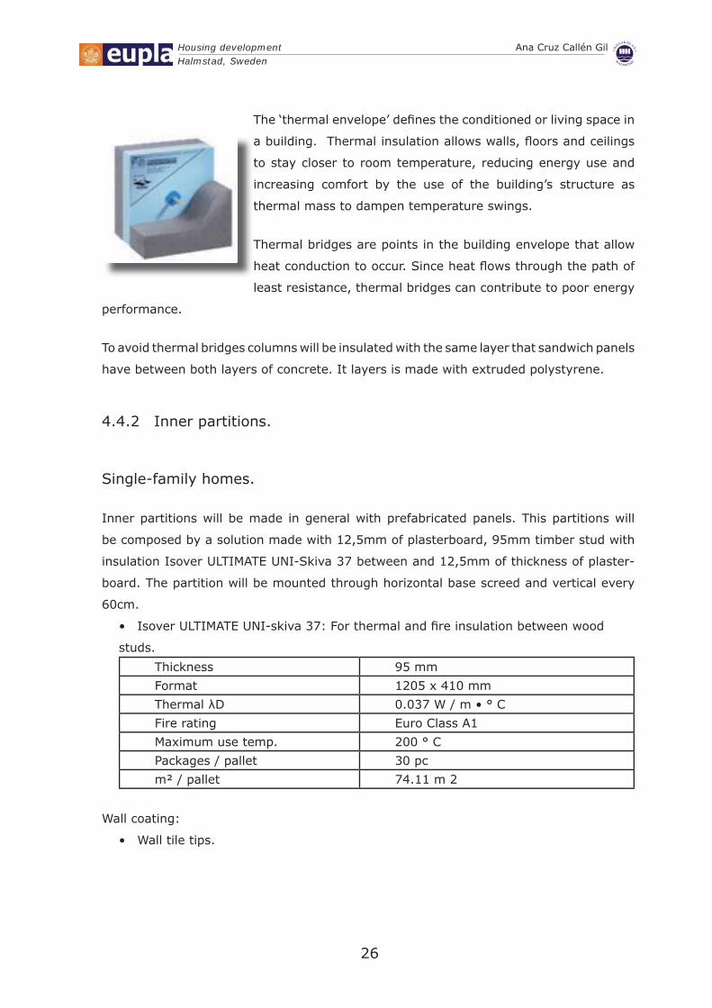
The ‘thermal envelope’ defi nes the conditioned or living space in
a building. Thermal insulation allows walls, fl oors and ceilings
to stay closer to room temperature, reducing energy use and
increasing comfort by the use of the building’s structure as
thermal mass to dampen temperature swings.
Thermal bridges are points in the building envelope that allow
heat conduction to occur. Since heat fl ows through the path of
least resistance, thermal bridges can contribute to poor energy
performance.
To avoid thermal bridges columns will be insulated with the same layer that sandwich panels
have between both layers of concrete. It layers is made with extruded polystyrene.
Inner partitions.4.4.2
Single-family homes.
Inner partitions will be made in general with prefabricated panels. This partitions will
be composed by a solution made with 12,5mm of plasterboard, 95mm timber stud with
insulation Isover ULTIMATE UNI-Skiva 37 between and 12,5mm of thickness of plaster-
board. The partition will be mounted through horizontal base screed and vertical every
60cm.
Isover ULTIMATE UNI-skiva 37: For thermal and fi re insulation between wood •
studs.
Thickness 95 mm
Format 1205 x 410 mm
Thermal λD 0.037 W / m • ° C
Fire rating Euro Class A1
Maximum use temp. 200 ° C
Packages / pallet 30 pc
m² / pallet 74.11 m 2
Wall coating:
Wall tile tips.•

Housing development Ana Cruz Callén GilHalmstad, Sweden
27
Tiled of kitchens and baths tile of stoneware enameled, of format 40x40cm., resistant
to cleaning products, received with cement mortar with lime or plasticized and sand of
metering 2:1:10, even with decorative border or serigraphy, pieces to miter in edges, mixed
with grout of white cement and fi nal cleaning, executed according to the regulations.
Paintings.•
Plasterboard will be installed on walls horizontally. Ceiling sheets will be installed parallel
to primary light source and where appropriate back-blocked. Where possible full sheets
should be used thus minimising the need for butt joints. Jointing will comprise a 3 coat
system. Each coat should be fully dried. The top coat will be sanded to a smooth, even
fi nish. Edges will be feathered in order to minimise scuffi ng of the paper face. Similarly,
internal and external corners, fi xings and cornice installation will be fi nished to the same
standard. This will deliver a substrate in a suitable condition to accept paint.
All walls and ceilings of interior, with exception of kitchens and baths will be painted
mastered angles and corners.
Sealing the Surfaces An essential fi rst step is to seal the face of the plasterboard and
the plaster joints with a good quality sealer/undercoat. This will ensure an even “suction
rate” and provide a degree of opacity for subsequent paint coats. The sealer/undercoat
could be considered as the most important component within the paint system. The
application of the sealer/undercoat should be carried out in such a way as to ensure that
the plasterboard paper face fi bres remain fl at.
Once the sealer/ undercoat has fully dried 2 top coats of water based paint will be applied
(ensuring adequate drying between coats)
The performance of the fi nished paint system and the appearance of walls and ceilings
are highly dependent on the quality of the paint used, application method, colour and
sheen level.
Expectations of Painted Plasterboard
A level surface with no visible joints •
A good sheen decorative•
These expectations will be diffi cult to achieve due to:
Poor design concepts •
Poor workmanship •
Poor quality paint •

Housing development Ana Cruz Callén GilHalmstad, Sweden
28
Failure to use a suitable sealer/ undercoat •
Glancing light due to natural and/or artifi cial lighting conditions •
Crowned or starved joints •
Insuffi cient drying times •
Dark coloured paints •
Gloss paints•
Floors.4.5
Single-family houses.
Floor framing consists of a system of sills and girders that provides support for fl oor loads
and gives lateral support to exterior walls.
Beams and girders are of solid timber in which multiple pieces are nailed together with
the wide faces vertical. Beams and girders that are not continuous are tied together
across supports.
2x13 gypsum floor board
15 mineral woll
22 chipboard
170 wooden beam
95 mineral wool
28 wooden for furring
Bearing partitions are placed over girders or walls which support the fl oor system.
Residential activity buildings.
They are made with hollow-core slabs with concrete topping. Pre-stressed, hollow-core
concrete slabs offer several advantages over in-situ fl oor casting, including speed of erec-
tion, lower building costs and consistent quality level
Slabs are 1200mm width and 200mm of thickness.
Housing development Ana Cruz Callén GilHalmstad, Sweden
29
A layer of dry lean concrete about 100mm thick covering the bottom of an excavation,
directly on the foundation. After that there are hollow concrete blocks to create an air
cavity. Hollow-core slabs cover hollow concrete blocks, dimensions of this slabs used in
all building are the same. Above of this slabs there is a layer of insulation of extruded
polyestyrene. Finally it will be installed a fl ooring heating.
Roof.4.6
Residential activity building:
In this building there will be two kinds of roofs. One of them covered all the second fl oor,
and the other one covered part of the fi rst fl oor, where there is a terrace. The roof of the
second fl oor will be a green roof made with pre-stressed hollow core-slabs with topping
concrete, arlita slope formation, polyestyrene foil, extruded polyestyrene, waterproofi ng,
one membrane protection layer, drainage layer other fi lter layer and moixture protec-
tion, the upper layer is composed of soil for planting. And the roof of the fi rst fl oor will
be passable fl at roof.
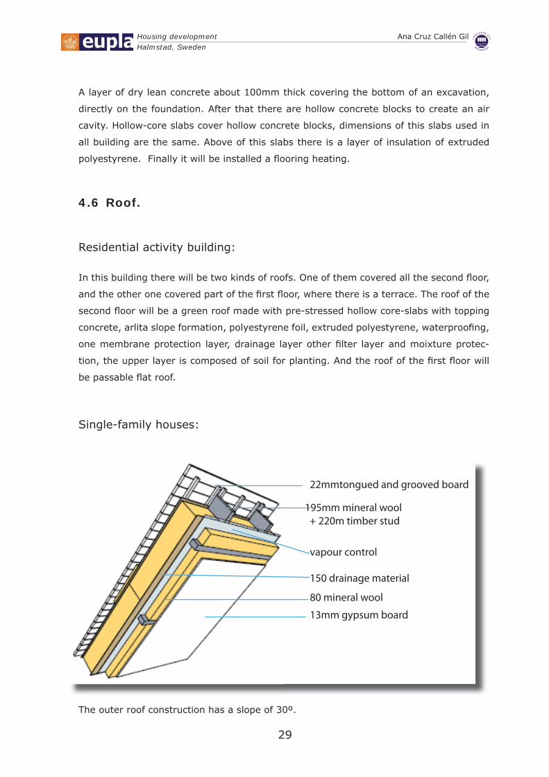
Single-family houses:
Single-family houses.Single-family houses.
195mm mineral wool + 220m timber stud
vapour control
22mmtongued and grooved board
150 drainage material
80 mineral wool
13mm gypsum board
The outer roof construction has a slope of 30º.
Housing development Ana Cruz Callén GilHalmstad, Sweden
30
False ceilings.
All the ceilings of the building will have a false ceiling with stucco plates, of dimen-
sions 1000x600mm sustained with esparto and paste of stucco E35 type, with perimeter
section of 80x200 and executed with stucco molding according to the regulation.
Installations.4.7
Ventilation:4.7.1
The primary function of the ventilation system is to maintain excellent indoor air quality.
The ventilation rates are determined according to national indoor air quality regulations.
It recommends a supply fl ow rate of 30 m3/h per person (8.5 l/s, person) and the system
should also allow for a minimum air supply setting for times with no occupancy, with a
corresponding air fl ow rate of 0.2 h-1.
When a ventilation heat exchanger is used, as in this project, the temperature of the
supply air delivered to the living area is preheated by the exhaust air, which helps to keep
a comfortable indoor temperature. The heat exchangers will have an effi ciency of at least
80% to minimize the ventilation losses. The unit will also be very quiet and it should be
easy to change filters.
The unit must be easy to clean and the energy use for the fans in the unit must be low.
Furthermore, the ventilation system will be equipped with a bypass of the heat exchanger
to keep the indoor temperature low in the summer.
The ventilation unit in an apartment building will be placed as small separate units in
each apartment. It is important that the ducts are carefully insulated. Ducts without
insulation could also cause a thermal bridge carrying cold outdoor air through the heated
area on its way to the heat exchanger and the supply air device.

Housing development Ana Cruz Callén GilHalmstad, Sweden
31
Airtightness in exterior walls
Only when the construction is airtight can warm air be retained within the building and
cold air kept outside. Preventing unpleasant draughts means greater living comfort and
increased energy effi ciency, which in turn leads to lower heating costs. Airtightness also
protects the building fabric against damage, helping to maintain its appearance and
extending the building’s life.
The ventilation cross-section between the bricks and the mineral wool is suffi cient to
ensure ventilation of the exterior skin.
Carpentry.4.8
Single-famiily houses.
Wood carpentry: All interior doors and windows are made with wood. They are fabricated
in Sweden, in accordance with the regulations.
Dwelling type 1: There are tive different models of doors, four of them will be blind with
moldings to varnish made pine of Sweden, claws of galvanized steel fi xation and lock
chromed. Exterior doors are well insulated with a low U value. This door and interior
doors are 1,02m of width and 2,14 of head height. There are two types of sliding door s,
one of them are used to one bathroom and to the laundry room, the others sliding doors
are situated in the exterior walls.
There are three different models of windows, two of them have the same dimensions and
their difference is that one type is fi xed and the other one can be open.
The windows will be from SP-windows, with a total U-value of 0.71 W/m2 K for the fixed
windows, and 0.85 W/m2 K for the operable windows. The glass, the distance between
the panes and the gas in the gaps were the same in both window types. This glass combi-
nation was also used in the terrace doors and resulted in a total U-value of the doors of
0.95 W/m2K.
Double-glazed timber windows are situated in the openings, their glass will be 4/6/4. It
means that the air cavity is 6mm of thinkness.
Housing development Ana Cruz Callén GilHalmstad, Sweden
32
Dwelling type 2: This house has four types of windows of different sizes but they will be
made with the same material that the windows described in the previous paragraphs
Residential activity building
Metallic carpentry. All the windows of the residential activity building will be made with
aluminium profi les hard anodizing of 15 microns, with quality steal, natural color, without
guide. The windows used are made with double insulating glass, with the same thickness
that windows used for dwellings. They made up of colourless glass 4mm, in the interior,
dehydrated air chamber of 6mm sealed, and colourless glass 4mm in the outside, with
double sealed of butyl and poly sulphur, executed according regulation.
Doors in scape routes have been chosen following BBR regulations in section of prevent
of fi re. To ensure that doors in escape routes equipped with an escape door system
conform with the required regulations, only three components are required as the control
electronics are already integrated in the terminal.
The panel for central monitoring and control is in BUS technology.
Fail-unlocked principle: Systems for locking escape routes operate according to the fail-
unlocked principle. In case of release, emergency unlocking or current failure, the door
is released without immediately.
The locking elements: The actual electrical locking mechanism is selected according to
use and the local conditions. It provides both electromechanical (form locked) and elec-
tromagnetic (frictionally locked) locking elements. The former are only used when fl ush
mounting is necessary for optical or security reasons.
The electromagnetic door locking mechanisms are used when doors in fi re barriers are
upgraded with escape door systems or when subsequent installation of an escape door
system does not require any structural changes to the door leaf and frame.
Surface holding magnets are also advantageous for doors that are frequently entered and
exited thanks to their virtually silent operation.
The hall sensor integrated in surface holding magnets activates a status check to the
control device and thus ensures protection against tamper and manipulation. A micros-
witch is responsible for this function in escape doors and panic strikes.

Housing development Ana Cruz Callén GilHalmstad, Sweden
33
Door of storage room will be made with panels of steel plate galvanized and stuffed of
injected polyurethane foam, forming panels of 40mm of thickness with acrylic painting
with lock of interchangeable cylinder. There will be also some doors situated in the upper
fl oor are made with steel and glass.
Salubrity installations4.9
Canalizations4.9.1
The canalization will be made of PVC with the diameters and lengths.
Drain spouts.
All the drain spouts of water evacuation are pluvial or residual and
all the water drainages of sanitary apparatuses and sinks will be made with PVC pipe hot
series of URAPLAST or similar, of diameter and lengths specifi ed in project. All the joints
and elbows will go with their corresponding meetings of union and special pieces. One
will consider that in all the water-drainages of sanitary apparatuses and sinks will have
to settle with their corresponding individual siphon.
Smoke ventilation and gases.
The evacuation of vapour and gases will be made through conduits of forced ventilation,
type “shunt”, formed by double pieces prefabricated, received with plaster paste type YG
Metallic grid and layer of heat insulation in the passages of forged and always according
to the practical standards of Construction.
Ventilation in the kitchens will be made by means of fl exible lamina tube of aluminium
and polyester, mounted on steel thread spiral with non-fl ammable tube of rigid PVC of
120mm will arrange in addition an extractor to smoke and gases, with centrifugal venti-
lator, of double aspiration and with single phase incorporated electrical motor, mounted
with vibration-proof systems and elastic connection in the mouth, with a power of 800
evacuation of m3/h. It will be demanded that the extractors have offi cial certifi cate of
operation.

Housing development Ana Cruz Callén GilHalmstad, Sweden
34
Plumbing installations.4.10
We have chosen: Wärtsilä BioPower plant for district heating in Halmstad.
Wärtsilä was awarded a contract to supply the equipment and installation for a biomass-
fuelled combined heat and power plant (CHP) by Halmstads Energi och Miljö AB (HEM), a
municipal company active in the energy and environmental sectors of the community.
The biomass-fuelled power plant, named KVV-Turbingatan, has a thermal output of 19.3
MWth and an electrical output of 3.2 MWe. The CHP plant supplies heat and electricity.
The plant uses wood residue from various sources as fuel. It delivers hot water to the
district heating network of Halmstad, a city of 88,000 inhabitants. Some of the hot water
also are used by local industry. The electricity produced is exported to the Swedish
national grid.
Wärtsilä’s biomass-fuelled plants are clean and effi cient. They are a practical solution
to the need for renewable energy supply with minimum environmental impact. They
incorporate patented Wärtsilä BioGrate combustion technology to burn biofuels with high
combustion effi ciency and low NOx and CO emissions.
The BioPower plant operates on a closed steam-feed water system separate from the
district heating water system. Steam is generated in an effi cient water-tube boiler, and
supplied to a back-pressure steam turbine driving an alternator. Turbine exhaust steam
then heats the district heating water and the condensate is returned as feed water to the
boiler.
Hot and cold water4.11
All the network of hot and cold water distribution will be made with electrolytic copper
pipe with meetings welded, in dimensions and diameters according to plane of project. It
will be installed, verifi ed and measured according to regulation.
Copper tube is used to convey potable water in buildings. Copper is used for plumbing
tube principally because of its corrosion resistance and high level of heat transfer.

Housing development Ana Cruz Callén GilHalmstad, Sweden
35
A heat exchanger is required in each dwelling. The unit provides thermostatically controlled
mains pressure hot water at high fl ow rates. This allows installation to be in almost any
position in the home.
The store is indirectly heated by primary water from the central district heating supply and
requires a minimum fl ow temperature of 80ºC for optimum effi ciency. The unit provides
heating and hot water to each dwelling. This use offers such benefi ts as:
No gas pipework•
No fl ue terminals•
No risk of carbon monoxide or other gases escaping and placing resident at risk.•
Landlords do not require annual gas safety certifi cates for the individual •
apartments.
Joining Tube: The method of joining copper tubing systems is soldering with capillary
fi ttings. Such joints are commonly used in plumbing for water lines and sanitary drainage.
Brazed joints with capillary fi ttings are used where greater strength is required or where
service temperatures are high.
Mechanical joints involving fl ared tube ends are used for underground tubing, for joints
where the use of heat is impractical and for joints that may have to be disconnected from
time to time.
Plumbing fi xtures: The bathroom fi ttings will be of vitrifi ed white porcelain. They have
faucets of ceramic chrome-plated discs. Its main features are shiny, mono-control with
airfl ow and individual siphon of water-drainage. The sink will be 1200x600 mm vitrifi ed
white porcelain. The total plumbing fi xtures will be accredited.
Heating.4.12
Single-family houses.
In a two-pipe system, steam supply to the heating units and condensate return from
heating units are through separate pipes. Air accumulation in piping and heating units
discharges from the system through the open vent on the condensate pump receiver.
Piping and heating units will be installed with proper pitch to provide gravity fl ow of all
condensate to the pump receiver.

Housing development Ana Cruz Callén GilHalmstad, Sweden
36
Each heating unit has a type supply valves, it admits steam to the heating unit through its
top inlet connection. Furtheremore the heating unist also have thermostatic steam traps,
they are located at the bottom outlet connection of the heating unit, thermostatic trap
stops fl ow-out of live steam, but opens to drain condensate and air into the return.
Electrical installations.4.13
As an electrical conductor for building wire systems, copper is the most effi cient, strongest,
most reliable metal available today.
Because of its strength, copper resists neck-down, creep, nicks and breaks. These are
the reasons it has been chosen in wiring systems throughout the dwellings and the resi-
dential activity building.
The electrical system will be made interlocked, with copper conductor of double protected
plastic isolation with fl exible tube of P.V.C., verifi ed and measured, according to the
construction regulations and Electro-technic Regulation of Low Tension. It will have a
general box of protection and magneto thermal switches in each circuit. The mecha-
nisms, boxes, etc., will be of the series Niessen Stylo or similar.
Electrical Code Requirements and Energy Effi cient Specifi cations:
One half of the kitchen lighting wattage must be High Effi ciency (fl uorescent or •
equivalent) and switched separately from other lights.
Kitchen counter tops will be provided with an electrical outlet at on centre. Ground •
fault circuit interrupters protection is required for these outlets. GFCI protection must
be provided in home electrical wiring for receptacle outlets installed in the following
locations:
Outdoors –
Bathrooms –
Garage –
Workshop –
Specifi c Receptacles in Basement Areas –
Kitchen –
Areas adjacent to a wet-bar in recreation rooms –
Hot Tubs, Jacuzzi Tubs, Swimming Pool Equipment –
Provide a minimum of 2 - 20 amp electric circuits for kitchen appliances.•
Provide 2 small-appliance branch circuits for outlets in the kitchen limited to •
supplying wall and counter space outlets only.
Housing development Ana Cruz Callén GilHalmstad, Sweden
37
The home electrical wiring for kitchens requires a 4-wire oven receptacle for elec-•
tric an range.
Isover 4.14
Products for air and wind-tightness. Polyestirene foil.4.14.1
A special water vapour retardant, non-woven, laminated climate membrane for sealing
and moisture protection in lightweight and solid construction.
External walls
Isover Vario Duplex: non-woven, reinforced, water vapour regulating climate •
membrane. Easy to lay, thanks to guideline markings For sealing the insulation layer
in all building elements. Excellent moisture protection for new buildings.
Format 40000 x 1500 mm
m² / pack 60 m 2
Partitions.
Wooden fl oor joist between heated rooms.
Isover takboard 33: Glass wool to be used as a load-distributing upper insulation •
board in several layers at the external insulation of the roof.
Thickness 15 mm
Format 2400 x 1200 mm
Thermal λD Premium Product 0.033 W / m • ° C
Density 125 kg / m 3
Fire rating Euro Class A2
Maximum use temp. 200 ° C
Pallet or package Stool
m² / pallet 201.6 m 2
Isover UNI-skiva 36: Glass wool for insulation between wood studs, wooden •
beams.
Thickness 95 mm
Format 1160 x 560 mm
Thermal λD 0.036 W / m • ° C
Density 16 kg / m 3
Fire rating Euro Class A1
Housing development Ana Cruz Callén GilHalmstad, Sweden
38
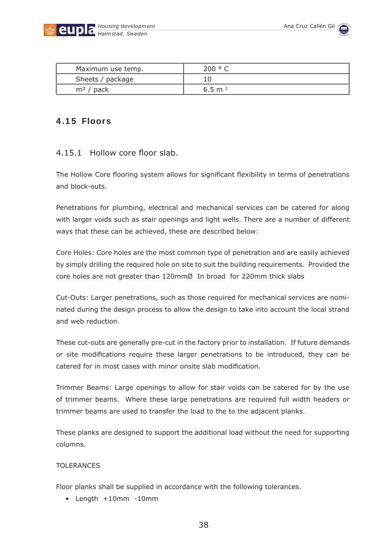
Maximum use temp. 200 ° C
Sheets / package 10
m² / pack 6.5 m 2
Floors4.15
Hollow core fl oor slab.4.15.1
The Hollow Core fl ooring system allows for signifi cant fl exibility in terms of penetrations
and block-outs.
Penetrations for plumbing, electrical and mechanical services can be catered for along
with larger voids such as stair openings and light wells. There are a number of different
ways that these can be achieved, these are described below:
Core Holes: Core holes are the most common type of penetration and are easily achieved
by simply drilling the required hole on site to suit the building requirements. Provided the
core holes are not greater than 120mmØ In broad for 220mm thick slabs
Cut-Outs: Larger penetrations, such as those required for mechanical services are nomi-
nated during the design process to allow the design to take into account the local strand
and web reduction.
These cut-outs are generally pre-cut in the factory prior to installation. If future demands
or site modifi cations require these larger penetrations to be introduced, they can be
catered for in most cases with minor onsite slab modifi cation.
Trimmer Beams: Large openings to allow for stair voids can be catered for by the use
of trimmer beams. Where these large penetrations are required full width headers or
trimmer beams are used to transfer the load to the to the adjacent planks.
These planks are designed to support the additional load without the need for supporting
columns.
TOLERANCES
Floor planks shall be supplied in accordance with the following tolerances.
Length +10mm -10mm•

Housing development Ana Cruz Callén GilHalmstad, Sweden
39
Width +3mm -6mm •
Thickness +3mm -3mm •
Squareness of end +6mm -6mm •
Bow / Wind 10mm per 3000mm •
Location of inserts +20mm -20mm •
Cover to strand +3mm -3mm •

40
Protection against fi re

Housing development Ana Cruz Callén GilHalmstad, Sweden
41
Protection against fi re5.
Laws and regulations5.1
Building legislation is required for the completed building. In construction laws (BVL) and
construction regulations (BVF) are rules that apply to all buildings and other structures.
These rules apply for the new construction.
BLM states that the fundamental technical performance requirements are:
Buoyancy and stability•
Safety in case of fi re•
Protection with regard to hygiene, health and environment•
Safety in use•
Protection against noise•
Energy economy and heat retention•
Fitness for purpose•
Accessibility and usability for people with limited mobility or orientation capacity•
Conservation of water and waste•
Regulations.5.2
Building Regulations (BBR) must be followed.
Safety In Case Of Fire.5.3
All lawful required measures have been followed regarding fi re-safety.
Mandatory rule and general advice in fi re-safety are collected from the Building Regu-
lations (BBR), section 5 . Guidelines for fi re resistance in Planning Design Regulations
(BKR) section 10 , and European construction standards (EKS), Section C.

Housing development Ana Cruz Callén GilHalmstad, Sweden
42
Documentation.5.3.1
According to (BFS 1995:17) section 5:12, the fi re protection documentation is drawn up
in the followings pages. This document set the conditions on which fi re protection is to be
based and the design of fi re protection.
In this documentation are set out the fi re resistance classes of the building and its compo-
nents, compartments, escape strategy.
Fire resistance classes.5.3.2
Classifi cation for buildings in Sweden are as follows: These Br1, Br2 or Br3 follow general
recommendation of the Board’s Design Regulations (BKR) section 5:21
The residential activity building of the project falls into the classifi cation, Class Br2 •
due to the large multipurpose room at ground level.
As started in the regulations, a place of assembly can be defi ned how any premises or
group of premises in a fi re compartment in which a large number of people who do not
have full knowledge of the premises may be present. In the upper level is the sport hall
which regarded as a place of assembly.
Normally, this building will be used by few people, as it is a private building, however, on
occasions, up to 60 people will be present.
Single-family houses falls into the classifi cation, Class Br3 due to the large multi-•
purpose room at ground level.
Escape in the event of fi re. 5.3.3
All buildings designed in this project allow satisfactory escape routes in case of fi re. This
implies either complete evacuation of people who are present in a building. Special atten-
tion has been paid in the common building as the risk is higher; as people may be injured
by the fall of structural or non-structural elements or due to panic and congestion, and
the risk that persons may be trapped.
Residential activity building•
Housing development Ana Cruz Callén GilHalmstad, Sweden
43
As is described in the regulations, in premises where people are present other than occa-
sionally must be provided with not less than two mutually independent escape routes and
if premises have more than one storey, at least one escape route shall be provided on
each storey. For this reason the common building is provided with four scape routes. Two
of them in the upper level and one more in the ground fl oor.
Single-family houses.•
A door leading directly to a street (principal access door) is the only escape route from
dwellings.
if it is necessary, windows can be used for emergency escape because at least there is
an openable without a key (as it is required by the regulation) and has a clear vertical
opening not less than 0.5 meters wide and not less than 0.6 meters high. The sum of
width and height are not not less than 1.5 meters. The bottom of the window opening are
not more than 1.2 m above fl oor level.
Separation from other escape routes in the residential activity 5.3.4
building.
Escape routes have been separated from one another in such a way that only one of them
can become full of smoke or blocked by the same fi re. Therefore have been subdivided
into sections of appropriate length so that prevent the spread of fi re gases.
As it is recommended by BFS 2002:19 regulation section 5:32, that escape routes
designed in the building have been separated from one another in the project of design
using a class to not less than E 15-C. Corridors have also been subdivided into sections
not more than 60 meters in length, separated from one another by construction to not
less than Class E15-C.
Travel distance to and along an escape route.5.3.5
The travel distance inside a fi re compartment to the nearest escape route allows perfectly
to a compartment be evacuated before critical conditions.
The maximum travel distance from the farest area is 26 meters and regulation advise
being less than 30 meters when the escape can be used in two directions.
Housing development Ana Cruz Callén GilHalmstad, Sweden
44
Access. The dimensions of escape routes 5.3.6
Escape routes have been designed to be spacious and to allow such ease of movement
that they are capable of serving the number of persons for which they are intended.
Following the BFS 2002:19 5 rules, the residential activity building have been designed
maximun to 60 people and the width of an escape route could be not less than 0.9
meters. In this case the width of the main access is 1.50 meters.
Doors in escape routes 5.3.7 Residential activity building.•
All doors in the escape route open outwards in direction of escape and they are easily
identifi able as exits. Doors situated in one scape route have been chosen to be open
easily, however, exterior doors are possible to open into an escape route from places of
assembly by merely pushing against the door or by opening it with an easily operated
handle. As it is said in BFS 1995:17.
Furthermore the doors in escape routes can be fi tted with a device which permits persons
to return after they have passed through. The force needed to open the door should not
exceed 130 Newtons applied to normal opening devices.
Single-family houses.•
Some inward opening doors are used in dwellings are permitted if they are intended for
a small number of people, such as detached houses of the project, because a moderate
number of people who live in this kind of construction may be expected to have good
knowledge of their houses.
Doors which can be opened only with a key are used in this houses because all people
who live in each house can have its own key to open the door in accordance with the BFS
1995:17 regulation.
Equipment 5.3.8 Guidance signs.•
Guidance signs for escape have been situated in every door or point where the people can
get confused to fi nd the escape way.
Housing development Ana Cruz Callén GilHalmstad, Sweden
45
Illuminated signs will be hanged on top of each door for every escape route, also fl oor
plans with scape routes will be placed near exit doors. The size of this panels will be
appropriate to be clearly visible. The panels have been made in accordance with the
regulations and general recommendations of the Swedish Board of Occupational Safety
and Health, Safety marking and safety signalling at places of work (BFS 1998:38).
Lighting.5.3.9
Escape routes are provided with general lighting which can work with a satisfactory
degree of safety in the event of escape from the building.
Emergency lighting permit escape in a safe and effective manner even in the event
of power failure. It is also provided in all stairways which are used in escape from a
building with more than eight storeys. Emergency lighting shall be provided The guid-
ance signs are provided with emergency lighting unless this is evidently unnecessary. The
emergency lighting shall perform its function in every escape route which has not been
blocked by fi re.
In the event of power failure the emergency lighting will provide the intended illumination
at least 60 minutes.
Electric cables for emergency have fi re resistance in accordance with class EI 30.
Evacuation alarm.5.3.10
Automatic fi re alarm system in the residential activity building is installed, smoke detec-
tors will be also installed. The system will send a signal to a staffed position when persons
are present in the building. In this building, it is not necessary loudspeaker.
The alarm can be activated automatically or from a staffed position when a fi re is
indicated.
As it is shown in (BFS 1998:38) the common building is provided with devices for the
early detection of fi re and evacuation alarms.
Housing development Ana Cruz Callén GilHalmstad, Sweden
46
Signals will be audible in all areas where people are present other than occasionally. The
early detection of fi re and evacuation alarms in this building is obtained by installing an
appropriate number (four os this in all building) of wired or battery operated self-con-
tained smoke alarms.
The place where alarms are placed is shown in the fi re protection plans.
In design with respect to the safety of escape, the conditions in the building do not
become such that the limiting values for critical conditions are exceeded during the time
needed for escape.
In evaluating critical conditions, special consideration has been given to visibility, thermal
radiation, temperature, noxious gases and the combination of temperature and noxious
gases.
This data is shown below:
Visibility: level of fi re gases not lower than 1.6 + (0.1 x H) m, where H is the height •
of the room.
Radiation: a short term thermal radiation intensity of maximum 10 kW/m• 2, a
maximum radiant energy of 60 kJ/m2 in addition to the energy from a radiation of 1
kW/m2.
Temperature: air temperature not higher than 80°C.•
Protection against the outbreak of fi re. Dwellings and residential 5.3.11
activity building.
Heat producing appliances, burners, heating installations and cookers, and fl ues have
been arranged so that they do not give rise to ignition of nearby structural or non-
structural elements, fi xtures or fi ttings. The temperature of the surface of nearby struc-
tural and non-structural elements, fi xtures or fi ttings of combustible materials has been
chosen to not exceed 85°C.
Heating panels or similar will be protected against being covered to the extent required
to prevent the outbreak of fi re.
Following the rule (BFS 2002:19), Parts of installations which may assume a temperature
higher than 85°C are insulated, the insulation is of material of not less than A2-s1,d0
(non-combustible material).

Housing development Ana Cruz Callén GilHalmstad, Sweden
47
The same rule that governs the preceding paragraph indicates that heat producing
appliances, fl ues and similar should be placed at a suitable distance away from nearby
structural elements, fi xtures and fi ttings made of combustible materials. The distance is
dependent on different factors as the area and the temperature of the radiating surface.
For an uninsulated and non-water jacketed heat producing appliance or an uninsulated
fl ue, a minimum distance of 0.5 meters is recommended. As an alternative, a cover made
of material of Class A2-s1,d0 (non-combustible material) may protect the wall against
radiance provided that the cover has suffi cient dimensions vertically and sideways and is
placed at an appropriate distance.
In this project there are some heat producing appliances and subsidiary fl ues this prod-
ucts have been selected with suffi cient strength to withstand the loads and other actions
to which they may be subjected.
Heat producing appliances, burners, and similar are placed on a base of suffi cient load
bearing capacity. This base shall be constructed so that the spread of fi re downwards is
prevented (BFS 1998:38).
Depending on the type of building, the base has been designed having as reference
the general recommendations of regulations. Following fi re resistance classes have been
chosen:
Residential activity building REI 60.•
In single-family houses to not less than class REI 15.•
Other recommendations: Gases shall not escape from heat producing appliances and
burners. The heat-producing appliance shall be supplied with a suffi cient amount of air
for combustion.
Heaters which have a rating higher than 60 kW are placed in boiler rooms, such as boilers
that heat water of the swimming pool, showers and jacuzzy situated in the common
building.
HEARTHS
Heat producing appliances for solid or liquid fuel shall be provided with a hearth. The
hearth shall have such size and be of such material that ignition of the fl oor is prevented.
If there is a clear space below the heat producing appliance or the bottom of the fi rebox,
the hearth shall also cover this space.
Following dimensions are required in (BFS 1998:38) section 5:42:

Housing development Ana Cruz Callén GilHalmstad, Sweden
48
The hearth of heaters for solid fuel should be not less than 2 meters wide in front of the
opening of the heater and not less than 1 meter outside other parts.
A hearth should consist of not less than 50 milliammeter concrete, tiles or similar.
For smaller enclosed heat producing appliances, the hearth should be provided up to a
distance of not less than 0.3 meters in front of the heat producing appliance and up to a
distance of not less than 0.1 meters on each side of the appliance.
At a tiled stove the lateral dimension of the hearth may however be limited to the width
of the opening of the stove plus not less than 0.2 meters on each side of the opening.
At an open fi re the hearth should be arranged so that the horizontal distance between the
centre of the fi re and the unprotected combustible fl oor is not less than 1.0 m.
If the bottom of the appliance is higher than 0.4 m above the fl oor, the distance should
be increased by one half of the vertical distance in excess of this fi gure.
Hearths for smaller heat producing appliances in habitable rooms may be of 0.7 mm steel
sheet.
Flue casings (BFS 1998:38) and (BFS 2002:19)
Flues made of materials that do not maintain their qualities after a chimney fi re shall be
surrounded by a casing of material of Class A2-s1,d0 (non-combustible material) with
suffi cient strength. The fl ue casing is designed so that the appropriate safety distance to
combustible material is maintained.
Depending on the type of building, the walls of the casing has been designed having as
reference the general recommendations of regulations. Following fi re resistance classes
have been chosen:
Residential activity building EI 60.•
In single-family houses to more than class EI 15.•
Subsidiary fl ues and lining tubes (BFS 1998:38)
Warm air heaters for heating premises in more than one fi re compartment, will be installed
in a boiler room. Neither supply air nor return air shall be taken from such boiler room.
The walls of ducts in the boiler room will be constructed so that the spread of fi re to both
supply air and return air ducts is prevented for 30 minutes. (BFS 2002:19)

Housing development Ana Cruz Callén GilHalmstad, Sweden
49
Protection against the spread of fi re inside a fi re compartment.5.3.12
The next text is written in the regulation: Materials in structural and non-structural
elements, fi ttings and fi xtures shall have such properties or form part of the structural
or non-structural elements in such a way that in the event of fi re they do not give rise to
ignition or rapid spread of fi re, nor do they rapidly evolve large quantities of heat or fi re
gases. They shall not melt and drip down outside the immediate vicinity of the seat of
fi re. The stipulated class of performance for the material depends on the quantity of heat
and fi re gases which can be permitted to evolve in the building. The choice of material
is dictated by the class to which the building is assigned. Materials in ceilings and walls,
fi ttings and fi xtures shall not be deformed when slightly affected by fi re and shall not fall
down or change in any other way so that the risk of injury to persons increases.
In spaces other than escape routes and such premises as mentioned in 5:513 the following
surface fi nishes should be selected:
The common building belongs to Class Br2:•
Ceiling surfaces have surface fi nish of not less than Class C-s2,d0 (Class II), applied to
material of Class A2-s1,d0 (non-combustible material) or fi re protection cladding.
Wall surfaces have surface fi nish of not less than Class D-s2,d0 (Class III).
In a building of Class Br3, as single-family houses:•
Ceiling and wall surfaces have surface fi nish of not less than Class D-s2,d0 (Class III).
Surface fi nishes and claddings in escape routes.5.3.13
As mentioned in the regulation, surface fi nishes and claddings in escape routes shall be
of materials which provide negligible contribution to the spread of fi re. In building of
Class Br2, ceiling surfaces and internal wall surfaces in escape routes shall have surface
fi nish of Class Bs1, d0 (Class I). The surface fi nish shall be applied to material of Class
A2-s1,d0 (non-combustible material) or to fi re protection cladding.
Floor coverings with a moderate propensity to spread fi re and evolve fi re gases will be
constructed to not less than Class Cfl -s1 (Class G). (BFS 2002:19)
Housing development Ana Cruz Callén GilHalmstad, Sweden
50
Surface fi nishes and claddings in certain premises.5.3.14
In places which presents a fi re hazard, walls and ceilings will be constructed so that
development of fi re in the premises receives no appreciable contribution from the surface
fi nish and claddings of ceilings and walls.
The fl oor covering in this places will be constructed of a material with a moderate propen-
sity to spread fi re and evolve fi re gases. (BFS 2002:19)
Protection against the spread of fi re and fi re gases between fi re 5.3.15
compartments.
The Residential activity building has been divided into fi re compartments separated by
structural or non-structural elements which impede the spread of fi re and fi re gases.
Each fi re compartment is comprise a room − or associated groups of rooms − In which
the activity has no immediate connection with other activities in the building.
Each fi re compartment is separated from other spaces in the building by structural or
non-structural elements constructed to not less than the fi re resistance class commensu-
rate with the requirements in next paragraphs.
The following areas; stairways, boiler rooms, storage rooms, and escape routes are
examples of self contained fi re compartment
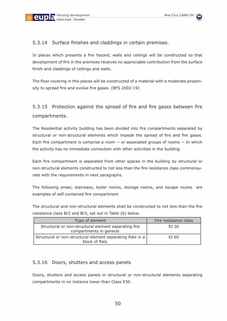
The structural and non-structural elements shall be constructed to not less than the fi re
resistance class Br2 and Br3, set out in Table (b) below.
Type of element Fire resistance class
Structural or non-structural element separating fi re compartments in general
EΙ 30
Structural or non-structural element separating fl ats in a block of fl ats
EΙ 60
Doors, shutters and access panels 5.3.16
Doors, shutters and access panels in structural or non-structural elements separating
compartments in no instance lower than Class E30.
Housing development Ana Cruz Callén GilHalmstad, Sweden
51
Doors and similar of material of Class A2-s1,d0 (noncombustible material) which satisfy
the requirements regarding insulation of Group 2 (previously Class A) and integrity in
accordance with the the Board’s general recommendations Guidelines for type approval,
Safety in case of fi re (BFS 1993:2) or corresponding previous regulations, may however
be used as alternatives to doors and similar of Class EI. (BFS 2002:19)
Doors and similar into, or inside, escape routes are self closing. Doors and similar into
spaces which are normally kept locked, situated above storeys where people are present
other than occasionally, need not however be self closing.
Self-closing doors are fi tted with a door stop provided that this automatically closes when
fi re gases are detected near it.
External walls and windows 5.3.17
In accordance with BFS 2002:19, Facade cladding shall not in the event of fi re evolve
heat and smoke to such an extent that escape and fi re fi ghting are impeded or in such a
way that there is a serious risk of injury to persons in its vicinity.
Facade cladding is made of low ignitability materials or comply with the requirement for
surface fi nish Class D-s2,d0 (Class III).
Windows in external walls 5.3.18
Windows in different fi re compartments which face one another have been designed
and situated so that the spread of fi re between the compartments is impeded. It is not
possible for such windows to be opened other than by a tool, key or similar.
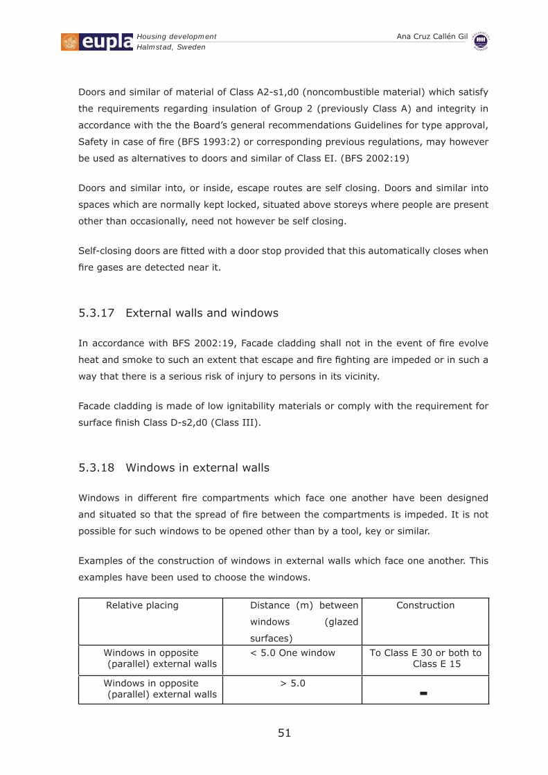
Examples of the construction of windows in external walls which face one another. This
examples have been used to choose the windows.
Relative placing Distance (m) between
windows (glazed
surfaces)
Construction
Windows in opposite (parallel) external walls
< 5.0 One window To Class E 30 or both to Class E 15
Windows in opposite (parallel) external walls
> 5.0 -
Housing development Ana Cruz Callén GilHalmstad, Sweden
52
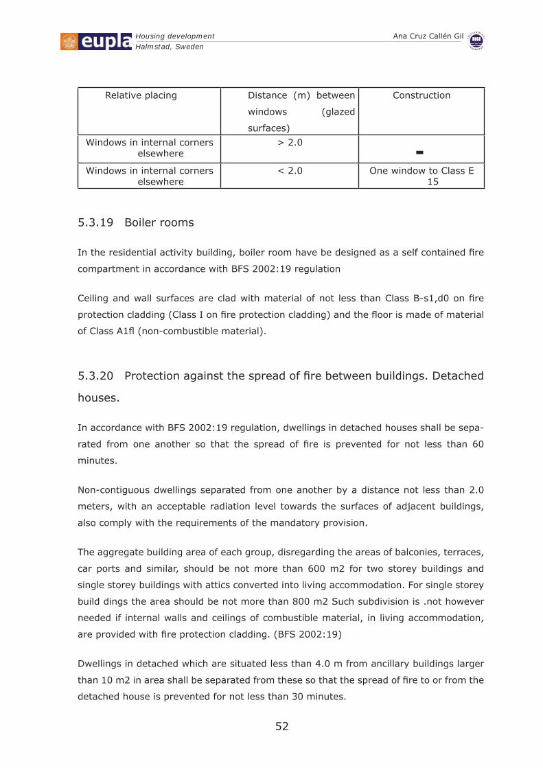
Relative placing Distance (m) between
windows (glazed
surfaces)
Construction
Windows in internal corners elsewhere
> 2.0 -Windows in internal corners
elsewhere< 2.0 One window to Class E
15
Boiler rooms 5.3.19
In the residential activity building, boiler room have be designed as a self contained fi re
compartment in accordance with BFS 2002:19 regulation
Ceiling and wall surfaces are clad with material of not less than Class B-s1,d0 on fi re
protection cladding (Class I on fi re protection cladding) and the fl oor is made of material
of Class A1fl (non-combustible material).
Protection against the spread of fi re between buildings. Detached 5.3.20
houses.
In accordance with BFS 2002:19 regulation, dwellings in detached houses shall be sepa-
rated from one another so that the spread of fi re is prevented for not less than 60
minutes.
Non-contiguous dwellings separated from one another by a distance not less than 2.0
meters, with an acceptable radiation level towards the surfaces of adjacent buildings,
also comply with the requirements of the mandatory provision.
The aggregate building area of each group, disregarding the areas of balconies, terraces,
car ports and similar, should be not more than 600 m2 for two storey buildings and
single storey buildings with attics converted into living accommodation. For single storey
build dings the area should be not more than 800 m2 Such subdivision is .not however
needed if internal walls and ceilings of combustible material, in living accommodation,
are provided with fi re protection cladding. (BFS 2002:19)
Dwellings in detached which are situated less than 4.0 m from ancillary buildings larger
than 10 m2 in area shall be separated from these so that the spread of fi re to or from the
detached house is prevented for not less than 30 minutes.

Housing development Ana Cruz Callén GilHalmstad, Sweden
53
General recommendation: The requirements of the mandatory provision can be complied
with if the facing walls of either building are constructed to not less than Class EI 30. If
one of the external walls has portions with no or a lower fi re resistance class, the safety
distance should be not less than 2.0 m and the radiation level towards the surface of the
nearby building should be limited to an acceptable level.
Roof covering 5.3.21
Design of roof covering has been done with following recommendations:
Roof covering on a material of Class A2-s1,d0 (non-combustible backing) may be made
of Class T.
Some spread of fi re may be permitted to occur in detached houses and in a residential
area outside a concentrated town centre development and on free-standing buildings.
In the case of single-family houses board material of low ignitability may be used as
cantilever roofs above carports and patios and as canopies above entrances. The risk of a
roof being ignited from a chimney serving a central heating installation shall be limited.

54
Health and safety study

Housing development Ana Cruz Callén GilHalmstad, Sweden
55
Health and Safety Study6.
Object of the Study of Health and Safety.6.1
A hazard is the potential for harm. In practical terms, a hazard often is associated with a
condition or activity that, if left uncontrolled, can result in an injury or illness. Identifying
hazards and eliminating or controlling them as early as possible will help prevent injuries
and illnesses.
A job hazard analysis is a technique that focuses on job tasks as a way to identify hazards
before they occur.
It focuses on the relationship between the worker, the task, the tools, and the work envi-
ronment. After identify uncontrolled hazards, we will take steps to eliminate or reduce
them to an acceptable risk level.
This Safety and Health study establishes, during the construction of the work, the fore-
casts respect to prevention of risks and occupational accidents so that all the works that
compose this work develop surely, avoiding dangerous actions or situations by lack of
foresight, lack of information on the possible risks or means insuffi ciency, as well as the
sanitary services common to the workers.
It will serve to provide basic directives to the constructions companies to carry its obliga-
tions in prevention fi eld of professional risks out, taking easy its development under the
control of the Coordinator in Security and Health during the execution of the work.
A Plan to Emergencies is described. It guarantees performance standards at the time of
facing situations of gravity, detailing the escape routes and places where the people can
keep out of harm.
General performances.6.1.1
The work consists of the construction of housing development located in Stationgatan
street of Halmstad (Sweden).
The promoter of this work is Halmstad University.

Housing development Ana Cruz Callén GilHalmstad, Sweden
56
The author of this Safety and Health study is Ana-Cruz Callén Gil, with professional offi ce
situated in Brogatan street, number 2 of Halmstad.
Training of employees6.1.2
Employers must ensure employees are either suffi ciently experienced to do their work
safely or are supervised by an experienced person. In addition, employees must be
adequately trained in the safe use of equipment in the place of work, including protective
clothing and equipment.
Safety of people who are not employees6.1.3
Employers are also responsible for the health and safety of people who are not employees.
Employers must take all practicable steps to ensure that employees do not harm any
other person while at work, including members of the public or visitors to the place of
work.
Accidents and serious harm (records and notifi cation)6.1.4
The law requires employers to keep a register of work-related accidents and serious
harm. This includes every accident that harmed:
Any employee at work;•
Any person in a place of work under the employer’s control.•
Main sources of risk in construction projects. 6.1.5 The common sources of risk in construction projects are listed below•
Misunderstanding of contract terms and conditions•
Design changes and errors•
Poorly coordinated work•
Poor estimates•
Poorly defi ned roles and responsibilities•
Unskilled staff•
Natural hazards•
Political and legal problems.•
Whit the Safety and Health Study all this risk will be prevented.

Housing development Ana Cruz Callén GilHalmstad, Sweden
57
Conditions of the surroundings.6.2
The rolled access is paved, reason why the accesses to future housing development
projected does not present any special problem
The plot has a surface of 15.538m2 and it topography is fl at. The site has regular form.
The streets which surround the plot are totally urbanized, referring to the services, the
plot has provision of electrical energy, water supply and residual water evacuation.
The water provision is predicted by means of a derivation of the potable water, being
pending of confi rmation on the part of the providing company the specifi c connection
point.
BUDGET EXECUTION OF THE PROJECT: 259.058,02 € + indirect costs.
IMPLEMENTATION TIME: two months and twelve days each dwelling type 1.
NUMBER OF WORKERS ANTICIPATED for the totality of the project will not surpass the
number of 10 workers with different specialities.
Site preparation.6.3
Before beginning the execution of a work, the fi rst thing that it will be necessary to
consider is the order of realization of the preliminary works, keeping in mind the risks
that can involve.
The characteristics of the building won’t only be known to build but rather, in the visit
to the land registrations will be located, wells, caskets and everything that indicates the
existence of underground conductions, will be requested to the suppliers companies of
service (water, gas, electricity) the different data where they are signal the situation of
the different facilities.
During the previous phase to the execution of the work will be defi ned the services which
can be affected, the level of risk that they offer, the provisional installations.
The provisional installation of water, besides being able to cause damages at third, will
also become special attention to the break of conductions of water that they can be the
cause problems in foundations of adjacent buildings.

Housing development Ana Cruz Callén GilHalmstad, Sweden
58
Finally, it will be necessary to check the existence of air or underground conductions and
to obtain the pertinent information on the same ones, furthermore, other consideration,
not less important than the previous one it will be to know the data corresponding to the
state of the nearest buildings.
For the storing of materials and machinery, it loads and it discharges, as well as the auxil-
iary works will be used one area of the plot.
Fencing around the plot.6.3.1
Before the beginning of the work, it will be carried out the hedge of the plot along all its
perimeter, maintaining a security distance from the fences until the border of casting of
lands similar to 2.00. This distance will stays in the perimeter of the work, in the access
for the machinery and It also stays in the staff access.
The hedge will be carried out with welded net, supported with metallic feet fi xed on bases
of reinforced concrete, assuring its assurance and resistance. It will present the following
characteristic:
The height of the barrier will be same or superior to two meters.•
Be diffi cult to climb •
Be diffi cult to gain access underneath •
Be stable and able to withstand anticipated loads •
Gates and joints in the fence should be secure and not present a weak point for •
entry.
An access will be enabled for vehicles of 5m. of width.•
Sheets of reinforcing mesh should not be used for site fencing as it allows adequate hand
and foot holds for children to climb over and the protruding ends of sheets could result
in penetrating injuries.
In case of emergency, the signs will be clearly visible from outside the site, stating the
names and contact telephone numbers of the person with control of the building work.
An independent access will be enabled for staff with a width of leaf of 1m, its height will
be 2m.
Besides this protection, Signalling boards will inform about general risks of the work.

Housing development Ana Cruz Callén GilHalmstad, Sweden
59
Signalling
It will present as minimum the following signalling:
No admittance to no unauthorised personnel.•
Forbidden the step of pedestrians for the entrance of vehicles.•
Safety helmets must be worn.•
Safety footwear must be worn on this site.•
All visitors and drivers must report to site offi ce.•
Danger men at work.•
High visibility jackets must be worn beyond this point.•
No smoking.•
Detection of the common hazards:Lifting and Carrying (Manual materials handling.•
Stooped postures.•
Whole Body Vibration.•
Preventive norms:Two-Mason Lift Technique.•
Use of portable storage carts.•
Worker rotation.•
Provisional facilities at work.6.4
Sanitary cabin.6.4.1
The construction is metal, facing with corrugated steel with double PVC coated; insulated
with EPS material or rock wool; PVC-lined panel.
Based on the maximum number of workers who can be found in work, we will determine
the necessary surface and elements for these facilities. In our case the greater presence
of simultaneous personnel obtains with 10 workers, determining the following sanitary
elements: one shower, two toilets, two washbasins and two mirrors.
Housing development Ana Cruz Callén GilHalmstad, Sweden
60
Changing room will be equipped with seats and individual lockers with key to store clothing
and footwear. Furthermore, it will be available warm and cold water in the shower.
Dining room are not necessary because there is a restaurant near the plot.
There will be a container for garbage collection.
Perfect state of cleaning and conservation will stay in.
In the work offi ce one will settle a fi rst aid kid with the minimum content indicated by the
effective legislation, furthermore there will be a portable fi re extinguisher.
Toilets
Workers will have access to conveniently located toilet facilities. The toilets will be
connected to the sewerage system. These toilets will be serviced in accordance with the
supplier’s information and instructions, before work starts.
To provide an acceptable standard of hygiene and privacy, the toilet must be:
Kept clean •
Weatherproof •
Well lit and well ventilated, either naturally or artifi cially•
Provided with a hinged seat and lid.•
Provided with a door which can be locked from inside.•
Provided with a well drained fl oor above ground level which is covered with a •
durable waterproof material
Provided with a plentiful supply of toilet paper •
Set up to remain level and stable under all working conditions. •
Where female workers are present on site, appropriate measures for sanitary item
disposal should be made, such as a disposal unit provided in the portable toilet or sewer
connected toilet closet.
Site offi ce.6.4.2
This prefabricated site offi ce cabin is compact and it has high structural strength.
Key specifi cations of Prefabricated Site Offi ce Cabin are:

Housing development Ana Cruz Callén GilHalmstad, Sweden
61
Easy to transport•
Dismantling / reassembling facilities•
Well insulated•
Maintenance free•
Storage container.6.4.3
The construction is metal, facing with corrugated steel with double PVC coated; insulated
with EPS material.
The fl oor structure is constructed of a metal grid elevated 120mm from the ground,
hydrophobic plywood of 22mm thickness and laminated fl ooring - Class AC3.
Electrical installation consists of junction boxes, fl uorescent lamps, outdoor lighting
fi xture, sockets and switches.
Joinery is constructed from four-glazed PVC profi les for windows and doors are made of
thick aluminum profi les.
Every corner of the storage container is equipped with brackets (ears), which permit the
loading and unloading activities when container is transported Transportation is done
with log truck with a crane.
Discharge of water from the roof is provided by the lateral corner columns.
Water supply
This underground canalization of drinkable water, residual or of watering are conductions
with fl ow and variable pressure before a break or overfl ow, they present fl ood risk, with
nuisances and delays.
In our work, the installation of a provisional net of supply of drinkable water will be
executed to satisfy the necessities.
Once it is hired the supply of the assault with the supplier company, it will be settled the
accountant, the general key and the exit to the different distributions.
Drinking Water

Housing development Ana Cruz Callén GilHalmstad, Sweden
62
A readily accessible and plentiful supply of drinking water will be available to all workers
on the site.
Mains water supply should be provided at the earliest possible time.
Drinking water facilities will be separated from toilet facilities to ensure adequate
hygiene.
Meal and shelter facilities 6.4.4
It will be provide hygienic and weatherproof meal and shelter facilities in an area acces-
sible to the building under construction.
These facilities will include:
Adequate seating (which could include a board across two trestles and other alter-•
natives to chairs) and a clean surface upon which to place food (could include an esky
provided by the worker or subcontractor or other material owned or controlled by the
relevant subcontractor)
A rubbish bin with a lid or appropriate alternatives for the hygienic disposal of food •
scraps.
Temporary Electrical installation.6.4.5
It is necessary to check the pertinent information about electric facilities. It is also neces-
sary to check places where cables of high intensity are.
Once this informations is known, the itinerary and depth of the underground conduction
will be marked with the maximum precision. The axis of the conduction will be traced,
being placed a board indicating the existent danger, being left an area of security, to
both sides of the excavation axis, of 1.5m. Underground conductions of electricity will be
cover with sand, bricks, tape of plastic in red colour and fi ller material.
With this information, it will be able to begin the works and provisional facilities of work.
The measures to take will be;
The trench will be made with excavating shovel until the depth authorized by the company.
Starting from there the excavation will continue with manual tools.

Housing development Ana Cruz Callén GilHalmstad, Sweden
63
The equipment of individual protection that the workers will use are helmets, gloves and
dielectrics boots and all tools used in this phase will be isolated.
Once we have covered the trench, we will determine the location of the cables following
the minimum distance between the different types of service with relationship to the level
of the sidewalk, the distances among conductions according to the regulations will be:
Electricity of High tension 1.2m•
Electricity of Low tension 0.7m•
Lighting 0.40m•
Low tension with telephony, water and gas: 0.20m•
The line used in this project will be low tension of 380 volts.
We will have to keep in mind that pointed out previously concerning to low tension line,
as according to the current regulations, this project will use this mode of tension.
Furthermore, for buried lines of low tension the minimum depth will be of 0.7m following
the side walk line and with a minimum separation of 1m.
We will also keep in mind that for the illumination their spread will be able to be carried
out following the line of sidewalks with the medium ones from roadway separation to a
minimum depth of 0.4m and a separation of the line of curb of 0.75m. Once open the
gutter;
Placement of layer of colored sand.
Placement of the protection conduction that it has also a certain colour.1.
Cover the conduction with colored sand and a plastic tape with an annotation.2.
Placement of line of bricks. 3.
When is fi nished this it will proceed to cover and compact the earth.
Detection of the common hazards:Sharp wound in hands•
Falls at the same level•
Electrocution: direct and indirect electrical contacts derived mainly from:•
Works with tension –
Try to work without tension but it is not total confi rmed. –

Housing development Ana Cruz Callén GilHalmstad, Sweden
64
Malfunction of protection mechanism and systems. –
Using of improper or damaged equipment. –
Bad behaviour or incorrect installation of the system of protection against –
indirect electrical contacts in general, and the ground in particular.
Preventive norms:All electrical outlets shall carry a ground connection requiring a 3-pronged plug.•
The grounding pin of a 3-pronged plug shall not be removed.•
All wiring operations shall be conducted by a licensed electrician.•
In the event that equipment becomes wet, or in the event of a water fl ood in the •
shop, power should be disconnected at the breaker, and a lock applied.
Electrical potential shall be discharged before conducting work on equipment •
containing high voltage power supplies or capacitors.
Use only CO• 2 or dry chemical extinguishers on electrical fi res.
For the prevention of possible indirect electrical contacts, the protection system chosen is
the grounding of the masses and cutting devices for fault current (switches).
Standard rules for preventing type cables:
The section of the electric wiring shall be according to the electrical charge that has •
to bear in terms of machinery and lighting provided.
All drivers used are isolated rated voltage of 1000 volts or higher and without •
signifi cant defects (tears and similar).
The distribution from the general panel of work to secondary panels will be made •
though buried pipes.
In case of use laying of cables and hoses , it will be done at a minimum 2m of •
height in pedestrians places and 5m in the cross of vehicles, measures above the
pavement.
The laying of the cables to cross road of work shall be buried. It will be marked •
”way of cable” using a permanent stud boards that it will target the protection through
burden sharing, and noted the existence of “electric cable” vehicles. The cable will be
protected inside a rigid tube.
In case of having to make joints between hoses will be considered:•
If it always will be high. It is forbidden to keep them on the fl oor. –
The interim joints between hoses will be made implemented trough stand- –
ardt connections watertight moisture.
The defi nitive joints will be completed using standard junction boxes water- –
tight security.

Housing development Ana Cruz Callén GilHalmstad, Sweden
65
The interconnection of the secondary panels will be made by buried pipelines.•
The layout of the electrical supple hoses will not match with the provisional water •
supply to plants.
The hoses like extensions:•
If they are for short periods may be stretched on the fl oor, but leaning against –
the vertical face. It will be rejoined by moisture sealed standard connections or
isolating sleeves heat shrink wrapping, with minimal protection against water
jets.
Standard rules for preventing type switchesIt will comply expressly specifi ed in the electro-low voltage Regulations.•
The switches will be installed inside standards panels, with security lock in the •
door.
The switch panels shall have a sticker standard sign on its door “danger, •
electricity”.The switch panels will be hung either the vertical walls or of “studs” stable.•
Standard rules for preventing type takes power:The outlets shall be fi tted with switches that allow court omnipolar tension leaving •
them if they have to be used.
The sockets for the tables are made of switchboards, standard pinarmored (protected •
against direct contact).
The circuit breakers are installed on all outlet lines distribution boards and power in •
the machinery and machine tools.
The earth leakage circuit breakers will be installed in accordance to the following •
sensitivities:
300mA: Power to the machinery. –
30mA: Power of machinery and enhanced level of security. –
30mA:For not portable electric lighting installations. –
The portable lighting will be fed to 24v. Transformers agency, preferably with –
separation of circuits.
Standard rules for ground connectionsThe transformer will be equipped with a ground connection adjusted to the existing •
regulations of supplying about the power company in the area.The metal parts of any electrical equipment have a ground connection.•

Housing development Ana Cruz Callén GilHalmstad, Sweden
66
The installation will be neutral grounded.• The ground wire will always be protected with macaroni in yellow and green. It is •
expressly forbidden to use it for other uses. Only driver may be used bare cooper cable of 95mm2 section at least buried horizontally and stretches that will be considered as artifi cial electrode installation.
The overall network of land will be unique for the entire installation including the • grounding connections of the rails to stay or moving cranes.
If the crane could approach a power line medium or high voltage insulator lacks •
adequate shielding, grounding, both must be electrically independent of the overall
network installation land interim electrical work.
Demolition.6.5
Demolition by hand.6.5.1
The fi rst phase will be a manual demolition, to recover and to be able to re-use most of
cables that now exist in the current building. Hand demolition is not the quickest method;
only hand tools are used. Cables must be removed regularly and not allowed to pile up.
Detection of the common hazards:Noise.•
Back injuries•
Electric shock•
Particles in the eyes •
Burns•
Cuts•
Strain•
Preventive norms:
Safety equipment protects must be used in accordance with the supplier’s instructions. A
number of hazards in demolition work require the use of personal protective equipment.
Employers must ensure that employees are provided with, and use, the following protec-
tive clothing and equipment:
Goggles•
Protective clothing•
Face shields•

Housing development Ana Cruz Callén GilHalmstad, Sweden
67
Hearing protection devices•
Gloves •
Appropriate respirators for dust•
Safety helmets and safety footwear must be worn at all times on demolition sites, •
except that operators may remove their helmets while inside a FOPs-protected cab
Hand tools
Common hand tool injuries can be avoided by observing the following safety rules:
Select the right tool for the job.•
Keep tools in good condition.•
Inspect tools regularly, and either replace or repair at once if found to be •
defective.
Use tools in a safe manner.•
Keep tools in a safe place at all times.•
Sledge hammers and picks: These are dangerous tools when their heads chip or come
loose from their handles. Hammer chipping can be reduced by:
Replacing a hammer head that is beginning to mushroom;•
Swinging only as hard as is necessary and safe;•
Hitting the target straight-on, never at an angle.•
Hammer heads fl ying off handles can be eliminated by carefully inspecting handles •
for cracks, splinters and looseness.
Chisels: the safe use of chisels begins with the selection of a sharp instrument of the right
size for the job, and a hammer of appropriate weight. Chisel heads that have begun to
mushroom should be ground to avoid the danger of fl ying chips. Goggles must always be
worn when chisels are in use.
Crowbars: A safe crowbar has a point that grips the object to be moved, and a heel to
act as a fulcrum. Makeshift crowbars, such as pieces of pipe iron bars, should be avoided.
They are more likely to slip or break and cause injury.
Shovels :back injuries are the most serious injuries resulting from the use of shovels.
To avoid such injuries, proper attention should be paid to the employee’s stance, their
lifting technique, and the way they turn and empty the shovel. Twisting the spine should
Housing development Ana Cruz Callén GilHalmstad, Sweden
68
be avoided: the legs, rather than the arms, shoulders, and back should be used wher-
ever possible. Employees should use the ball of the foot rather than the arch to push the
shovel. That way, if the foot slips the shovel’s sharp corner will not cut the ankle
Mechanical demolition.6.5.2
Hydraulically operated excavators fi tted with pusher arm.
The main advantages of such machines are that they are extremely mobile, have a high
output, and are able to work on vertical faces and fl oors above standing level. The disad-
vantages are that the machines need adequate access, a fi rm and relatively fl at base to
work from, and can only work within the reach of their booms. To operate these machines
effi ciently, the length of boom when fully extended should
be at least 1.5 metres above the height of the building being demolished.•
The pusher arm method is suitable for small buildings as this. •
The building is pushed over by a horizontal force from the machine.•
Using this method, always:•
Work from outside the building and never let anyone enter the building while plant •
is wrecking the building.
Be sure the operator has been trained in the work or is being instructed by a trained •
person.
Use hand demolition to get the building to a level where pushing can start.•
Make sure the debris does not build up•
Movements of Lands6.6
Description and organization of the works.
The topography of the land is sensibly horizontal without appreciable differences.
The earth movements to carry out are:
The cleaning of the layer of earth.•
The excavation of the land until arriving to the bench mark required for the support •
of the foundation.
Housing development Ana Cruz Callén GilHalmstad, Sweden
69
Excavations and trenches6.6.1
Before excavation work is carried out, the relevant person or principal contractor, for
construction work, must:
Find out what underground services exist•
Obtain relevant information about the service (location, type, depth, restrictions to •
be followed)
Record the information.•
A relevant person must:
Consider the information•
Follow any reasonable restrictions•
Implement necessary control measures.•
A relevant person is responsible for managing the risks associated with:
An excavation collapsing•
Objects falling into an excavation•
A person falling into an excavation•
A hoarding at least 900mm must be erected around an excavation of swimming pool.
A barricade at least 900mm high must be erected around a trench that is 1 metre or more
deep unless it is not possible or only workers involved with the trench will be in the area;
or another form of barrier exists, for example, excavated materials near the trench.
Excavated or other loose material must be effectively stored or retained not closer Than
600mm from the edge of the face unless the face is specially shored to allow for the
increased load, and suitable toe boards or other safeguards are provided
Mechanical plant, vehicles or any heavy loads must not approach closer than 600mm
from the edge of an excavation.
Detection of the common hazards:
In the clear:
Accidents, blows and collisions with machines and vehicles•
Overturns and false manoeuvres of the machinery for movement of lands (exca-•
vating machines and trucks)
Housing development Ana Cruz Callén GilHalmstad, Sweden
70
Noise and vibrations•
Over efforts•
In the realization of the excavation:
Fallen to the same one and the different level of people or machinery•
Landslide of the land, buries (for fi ltrations, vibrations, it overloads, etc.)•
Accidents, blows and collisions with machines and vehicles•
Overturns and false manoeuvres of the machinery for movement of lands (exca-•
vating machines and trucks)
Fall of objects from a superior level•
Floods•
Noise and vibrations•
Over efforts•
Preventive norms
In the clear:
Because of the many services such as electric power cables, telegraph cables, gas •
pipes, water pipes, oil pipes and sewer reticulation that are located underground,
employers must, before starting work, ascertain the location of all services that are
likely to be affected by the excavation. The owners of these services must be advised
and their assistance sought.
It will be limited the interference with third placing foot barriers in passing in areas •
of pedestrians, making you use of the signalling if it is affected to circulation roads,
using you signs as: “Warning gutters”, Use of PPE.
The minimum distances of separation will be delimited among operatives in func-•
tion of the tools that use.
The operatives who don’t manage the machinery, will remain outside of the radius •
of action of the same one, paying special attention when they develop their work near
the machines.
The works will be suspended under the regimen of rains.•
In excavations when the vehicles circulate in normal direction to the cut, the •
enclosed area will enlarge that direction in two times the depth of the cut and not less
than 4 meters when it is necessary to place signalling of reduction of speed.
When the extracted lands are polluted they will be disinfected as well as the walls •
of the corresponding excavations.
Anybody won’t work simultaneously in vertical different levels of the same one. In •

Housing development Ana Cruz Callén GilHalmstad, Sweden
71
the event of having to work under these conditions, the operative of the inferior level
will remain with the helmet of security during his work.
They will be revised the contentions before beginning the work day, tightening the •
elbow pieces when they have loosened
These preventions will be carried to an extreme after work interruptions of more •
than 1 day and/or atmospheric alterations as rains or icy.
In the event of presence of water (strong rains, breaks of pipes, fl oods, etc.) it will •
proceed immediately to its reduces, in prevention of alterations of the land.
The extracted lands will be gathered at a distance of the border of the excavation.•
The contention elements won’t be used to ascend or to lower the gutter.•
The contentions or part of these will take off when they stop to be necessary only •
and for horizontal fringes beginning with the inferior part of the cut.
Any step that is necessary to make on the gutters, will be made with gangplanks •
protected in its perimeter with handrails of 0.90 m, intermediate bar and baseboard.
It will prepare in the work, to provide in each case the indispensable team to the •
operative, of a provision of levers, wedges, bars, props and planks that won’t be used
for the contention and they will be reserved for their use by the salvage team, as well
as of other means that can be good for eventualities or the operatives’ aid that could
have an accident.
In the works in gutters will have a signal list in the hoisted of loads when the •
maneuvers are diffi cult or the fi eld of vision is limited. The operatives won’t remain
under the loads.
It will be verifi ed the state of the elements daily of hoisted elements.•
It will be placed some endings which prevent that the vehicles approach on the •
edge of the gutters.
To humidify the front of attack of the excavation to eliminate the powder that takes •
place as much as possible.
When the level of noise taken place by the used machinery will be equal or bigger •
than 80 decibels the operatives has to use auditory plugs.
Personal protection equipment:In the clear and in the excavation of gutters and wells:•
Polyethylene helmet (workers will use it, machinists and truck drivers that want or •
they should abandon the booths of conduction of the vehicles will use it too).
Security footwear•
Security rubber boots (or PVC)•
Leather gloves and canvas against mechanical risks•

Housing development Ana Cruz Callén GilHalmstad, Sweden
72
Work clothes•
Raincoats for humid or rainy atmospheres•
Auditory protection in works with pneumatic machinery•
Glasses against projections•
Mask of fi lter mechanic (against powder)•
Lumbar bands•
Machinery for the movement of lands.6.6.2
Detection of the common hazards:Overturn of the machine.•
Accidents.•
Those derived of the maintenance operations.•
Vibrations and noises.•
Thermal stress•
Environmental powder and blows.•
Fallen when ascending or to get off the machine.•
Collide against other vehicles.•
Blows with parts motives of the machine, to be in their action radio•
To cross with electric lines•
Fires and explosions •
Preventive norms:The handling of the machines will only be allowed to bigger than 18 years, with •
the formation and appropriate professional category, he/she will be proven that each
driver has received the specifi c norms of security for his machine.
They will be behind endowed with march lighthouses and advance, rear-view in •
both sides, luminous and acoustic signs.
They will be endowed with a bridge of security antiovverturning and antiimpact.•
They will be endowed with a stamped extinguisher and with the corresponding •
revisions.
Warning signs and stuck signs will be placed or received in the chassis of the •
machine.
They will be inspected controlling the good operation of the motor periodically, •
hydraulic systems, controls, address, lights, acoustic signs (horn setback), transmit-
ters, chains, tires and booth.

Housing development Ana Cruz Callén GilHalmstad, Sweden
73
Do not work or to remain inside the radius of security of 5 meters of the arm of •
action of the machinery.
The distance to any line of high tension will be as minimum 5 meters•
It won’t be allowed to transport people on these machines, to avoid risks of acci-•
dents of fallen.
They will settle you collide of security of journey end, before the coronation of •
courts of banks or embankments, marking the distance of approach of the machinery,
to avoid the risks for the fall of the machine.
The roads of internal circulation will be signalled by means of small fl ags and •
normalized signs of traffi c.
The drivers of the machines won’t be able to abandon them without stopping the •
motor of the same ones, leaving the motors on the dot dead.
Is not allowed the maintenance works or repair of the machinery with the motor in •
march, in prevention of unnecessary risks.
The entrances and exits of the work will be carried out with caution, assisting the •
signs of an operative in charge of the maneuvers.
The loads to transport will be the appropriate ones (not to surpass the maximum •
load) taking care that they don’t stand out to avoid accidents.
Is not allowed in this work the realization of replants you or of mensurations in •
the areas where they are operating the machines for the movement of lands. Before
proceeding to the enunciated tasks, it will be necessary to stop the machinery, or to
move away it to other cuts.
Is not allowed the storing of lands to less than 2 m. of the border of the •
excavation.
It won’t be dug beyond the vertical of the machine.•
They will be parked or they will park outside of the work area •
Personal protection equipment:
If exists expressed approval of the Ministry of Work and Social Security, the garments of
personal protection to use in this work, they will be homologated.
Polyethylene helmet. Class N. (of obligatory use to abandon the booth).•
Security glasses, Class C (in case the machine doesn’t have booth)•
Leather gloves.•
Work clothes.•
Clothes for rainy time.•
Security nonskid boots. Class III.•
Protective auditory (obligatory if the beginner of noise is superior to 80 dB).•
Housing development Ana Cruz Callén GilHalmstad, Sweden
74
Mask anti powder (in the event of being necessary)•
Belt abdominal anti vibration.•
Structure6.7
The accomplishment of a compound structure by precast concrete columns, on site
concrete footings, pre-stressed concrete beams and hollow core slabs with topping
concrete.
It will be determined that the erection platform can support the construction and erection
loads and provide verifi cation to the crane owner/operator prior to the commencement
of the work.
Erection preparation
Prior to commencing the handling and/or erection of precast concrete elements, the
following items should be considered by the manufacturer or builder as appropriate.
Check access to the site to prevent trucks damaging fl oor during access. •
Obtain verifi cation that the erection platform can support the erection loads.•
Ensure the locating dowels and levelling shims are correctly located. Dowels rather •
than blocks should be used to restrain the base of face-lifted panels when they are
being positioned.
Clear the site for truck and crane access ensuring room for crane outriggers, coun-•
terweight tail swing, boom swing and under hook and overhead obstructions.
Ensure that suffi cient space is available for precast propping or panel bracing.•
The builder must ensure that adequate temporary base restraint is provided for any •
precast element to prevent a sliding failure at the base or support of the element.
Check that the means of temporary support, including false work is adequate for the •
intended purpose and located correctly prior to the precast elements being placed.
Verify that the concrete has obtained the specifi ed strength for lifting. This may •
already have been done if the element was manufactured off-site.
Check that the lifting inserts are in their correct location and that recesses are •
cleaned out in preparation for lifting.
Check that the strong backs, if required, are available and correctly installed.•
Determine if it is necessary to equalise loads on lifting points.•
Ensure that the appropriate rigging equipment is available. This includes lifting •
beams and correct attachments for cast-in anchors or inserts.
Wherever possible the lifting of tilt-slab panels should be under taken from within •
Housing development Ana Cruz Callén GilHalmstad, Sweden
75
the building envelope. In this way, the crane operator is able to keep the rigging and
lifting eyes in view at all times.
Erection should be possible without the need for any worker to be positioned under-•
neath a precast element or on the underside of a tilt-up panel during erection.
For general precast elements, such as beams or fl at slabs, care should be taken to deter-
mine if it is necessary to equalise loads between lifting points on any element.
formwork:6.7.1
Form: the form of the slabs for dwellings and for footings in the residential activity build-
ingg will be of wood.
Detection of the common hazards:Lossening by badly piled up of the wood.•
Blows in the hands during nailing.•
Upsets of the wood packages (planks, boards, props, strap, supports, etc), during •
he manoeuvres of hoisting slabs.
Fall of wood to the emptiness during the operations of take out the formwork.•
Fall of people by the edge or hollows of the forged one.•
Fall of people at the same level.•
Cuts when using the hand mountain ranges.•
Cuts when using the circular mountain range of table.•
Footsteps on sharp objects.•
Electrocution by cancellation of land takings of electrical machinery.•
Over exerts by inadequate positions.•
Blows in general by objects.•
Dermatoid by contacts with the cement.•
The derivates of works on wet surfaces. •
Manipulation of the concrete 6.7.2
Detection of the common hazards:Fall of people at the same level.•
Fall of people y/u objects at different level.•
Housing development Ana Cruz Callén GilHalmstad, Sweden
76
Fall of people y/u objects to the emptiness.•
Formwork collapse.•
Formwork breakage.•
Footsteps on sharp objects.•
Footsteps on transit surfaces.•
The derived ones from works on humid or wet grounds.•
Contacts with the concrete (dermatitis by cements).•
Tramping.•
Electrocution. Electric touches.•
Preventive norms: Spill by means of bucket or bucket.•
Forbidden to load the bucket over the permissible fully factored load of the crane •
that sustains it.
The opening of the bucket for spill will be executed exclusively by the incorporated •
suitable mechanism to the same one in avoidance of accidents by blockage or corks.
Before the beginning of the spill of the concrete, the Overseer (or Ordered), will •
review the good state of security of the timbering of territories containment of the
slopes of the drained one that they interest to the zone of wall that goes away has to
concrete, to make the reinforcements or sanitation that were necessary.
The access to extrados of the wall (formwork space between external and the slope •
of the drained one), will take place by means of ladders: Forbidden access, formwork
climbing, being an uncertain action.
Before the beginning of the concrete one, the Overseer (or Ordered), will review the •
good state of security of the formworks ones in prevention of blow-out and I spill.
Before the beginning of the concrete, and as the formwork ends of the works of, •
the servicing platform of coronation of the wall from which will have been constructed
to help the workings of vibrated spill and.
The formwork for spill and vibrated platform of coronation of, that will settle down •
all along of the wall; it will have the following dimensions:
Length: The one of the wall.•
Width: 60 cm., (3 planks minimum). -Attachment: Struts on the formwork.•
Protection: Railing of 90 cm. of height formed by banister rails, intermediate strip •
and end tile of 15 cm.
Access: By means of prescribed ladder.•
They will settle down to a minimum range of 2 m.s, (like general norm), forts tops •
of end of route, for the vehicles that must on the brink of madness come near the

Housing development Ana Cruz Callén GilHalmstad, Sweden
77
slopes of the drained one, to spill the concrete (Dumper, truck, concrete mixer).
The concrete spill in the interior of the formwork one will be made distributing it •
throughout the same one uniformly, by regular layers, in avoidance of overloads props
that can deform or burst the formwork.
Work at heights6.7.3
(Excluding work on ladders or trestle ladder platforms and scaffolding work)
Risks must be managed if a person could fall less than 3 metres (housing construction),
2 metres if work is on a roof pitch not more than 26°. Hazards that may present a risk
from a fall include:
Vertical reinforcing steel, the edge of a rubbish skip, a picket fence, or a stack of •
bricks below workers
unsheeted fl oor bearers and joists 2 metres below workers•
Work on a brittle roof.•
Factors such as the type of activity being carried out should be taken into consideration
to establish the degree of risk.
Control measures used to manage risks must comply with regulatory requirements.
Detection of the common hazards:
Relevant people carrying out work above these heights or on a roof pitch more than 26°
must:
prevent a fall•
if prevention is not possible, arrest the fall and prevent or minimise the risk of •
death or injury from the arrest of the fall.
Preventive norms:
Edge protection systems around elevated work areas must:
be erected and used in accordance with the instructions of the manufacturer, •
supplier, engineer or competent person
be designed to withstand a force which may reasonably be expected to fall against •
it be at least 900 mm high.

Housing development Ana Cruz Callén GilHalmstad, Sweden
78
A fall protection cover placed over holes and openings must be:
able to withstand the impact of a fall onto it of any person who may reasonably be •
expected to fall onto it
be securely fi xed in place to prevent it being moved or removed accidentally.•
A travel restraint system is a personal fall prevention device and must:
not allow a free fall either from an edge or through the work surface•
be installed by a competent person and be inspected by a competent person at •
least every six months (a written record of the inspection must be obtained)
have an anchorage point with a capacity to withstand any load that could be exerted •
on it in its normal operation
only be used by a person who has been trained in the safe and correct use of the •
system
not to be used if a component of the system shows evidence of wear or weakness •
to an extent that may affect the system’s safety.
A fall arrest system consisting of harnesses or ladder belts attached by lanyards to a suit-
able anchor point must:
Have each anchorage point:•
Designed by an engineer and inspected and approved by a competent person before it
is fi rst used
With a capacity of 12 kN, if only 1 person is using the anchorage point and –
the person could have a limited free fall
With a capacity of 15 kN, if only 1 person is using the anchorage point and –
the person could have a free fall
With a capacity of 21 kN, if 2 people are using the anchorage point –
Have each anchorage point located so that the person using the system can attach •
a lanyard without the risk of falling
Limit the force applied to a person by a fall to not more than 6 kN by the use of a •
personal energy absorber
Be installed and maintained in accordance with the instructions of the manufac-•
turer, supplier, engineer or competent person
Have suffi cient free fall distance taking into consideration:•
The person’s height –
the height and position of the anchorage point –
the length of the lanyard –
any slack in the static line –
any stretching of the lanyard or static line when extended by a fall –

Housing development Ana Cruz Callén GilHalmstad, Sweden
79
the length of the energy absorber when extended by a fall –
any other relevant factor –
Have no part of the system come into contact with anything that could affect the •
safe use of the system
Only be used by a person trained in the safe and correct use of the system•
Have written safe rescue procedures•
Not to be used if a component of the system shows evidence of wear or weakness •
to an extent that may affect the system’s safety
Be inspected by a competent person at least every 6 months (a written record of •
the inspection must be obtained)
Not be used after a fall unless its manufacturer or a competent person has inspected •
it and decided that it is fi t for safe use
Not be used by a person working alone.•
Twin tail fall arrest lanyards failure can be fatal - recommendations for design and lanyard
assembly.
An industrial safety net must:
Be designed by an engineer or competent person•
Be made of material designed to minimise injury to a person falling into the net•
Have energy absorbing characteristics to reduce the shock or injury to a person •
falling into the net
Be installed so that a person falling into the net will not hit anything below the net•
Be installed as close as possible below to where the person is working but not •
more than the distance specifi ed by the manufacturer, supplier, engineer or competent
person
Be installed, used, installed and maintained in accordance with the instructions of •
the manufacturer, supplier, engineer or competent person.
Permanent facilities 6.8
Description and organization of the works
The permanent facilities can be subdivided in:
Mechanical: elevators, electricity, plumbing, gas and special facilities•
Termomechanics: heating, air conditioning, ventilation. •

Housing development Ana Cruz Callén GilHalmstad, Sweden
80
The trust factor increases the number of accidents.
Detection of the common hazards:Cut for the handling of foils•
Cut for the managing tools with edge•
Cut for the use of the glass fi bre•
Risks that are detected during the connection tests and setting inservice of the •
installation.
Fall of personal to the same and different level•
Fallen of objects•
Cut for handling of manual tools•
Cut for handling of the guides and drivers•
Being the most common the electrocution or burns, for the bad protection of electric
boxes, for incorrect manoeuvres in the lines, for use of tools without isolation, for bridge
of the protection mechanisms, for direct connections without pegs male-female
Trappings among heavy pieces•
The inherent ones to the use of the autogenous, electric welding, oxiacetilénic and •
oxicut
Footfalls on sharp objects•
Burns•
Over efforts•
Direct and indirect electric contacts•
Explosion of the torch or of the deposit of liquefi ed gas•
Trappings between engagements and transmissions, during the setting operations •
to point or assembly
The inherent accidents to the auxiliary equipment to use•
Dermatosis for contacts with fi bers •
Personal protection equipment:Polyethylene helmet, during the displacements for the work and in places with risk •
of fall of objects or of blows
Insulating boots for electricity (in connecting works)•
Security boots (in wired)•
Insulating gloves•
Leather gloves•
Work clothes•

Housing development Ana Cruz Callén GilHalmstad, Sweden
81
Security belt. Types TO, B and C•
Belt appropriate behaver-tools•
Insulating carpet•
Checkers of tension•
Insulating tools •
For welding works:
Welder’s glasses•
Welder’s helmet•
Hand or fi xed welder’s screen•
Leather gloves•
Rubber gloves or of PVC•
Leather wrists that cover the arms•
Leather leggings•
Leather apron •
Permanent electric facilities 6.8.1
Description and organization of the works
The taking of earth will be carried out with cable. That specifi ed in the Electrotech-
nical regulation of low tension will be continued in any event (it has already been justi-
fi ed before in the memory the reason why we will make use of the spanish normative
regarding the facilities).
Detection of the common hazards:Electrocution or burns for incorrect maneuvers in the lines•
Electrocution of burns for use of tools without appropriate isolation•
Electrocution or burns for check of protection mechanisms•
Electrocution or burns for direct connections without pegs male-female•
Fallen to the same and different level•
Cut and blows for handling of manual tools•
Cut for handling of guides and drivers•
More common risks during the connection and setting in service of the installation•
Electrocution or burns for bad protection in electric boxes•

Housing development Ana Cruz Callén GilHalmstad, Sweden
82
Preventive norms:The portable electric tools will have double isolation of security•
The security belts won’t be used if they have deformed rings, or break points are •
appreciated
The embedded conductors will be located in horizontal or vertical address, avoiding •
to cross the walls in diagonal
The work place will be often ordered and cleaned in the phase of opening work and •
closing of holes for facilities, to avoid the risks of footfalls or stumbles
The illumination of the cuts won’t be inferior to 100 lux measured to 2 meters of •
the fl oor
The illumination by means of portable ones will be made using tight lampboxes with •
insulating handle fed to 24 volts
Use of the pegs male-female•
The use of hand stairways or of scaffolds in places with fall risk from heightIt will •
be forbidden in work, installing the appropriate protection of security
The tools to use will be protected with normalized insulating material •
If a fi re was originated in an installation in tension, they will come in the following way:
The sources in tension will be disconnected•
Extinguishers that have the indication of not using in presence of electric current •
won’t be used
Insulating gloves will be used to hold the extinguisher•
The extinguisher will be at a minimum distance of 0.50 meters of the fi re during its •
use in facilities of low tension.
Personal protection equipment:Security helmet•
Insulating boots for electricity (in connection works)•
Security boots (in wired)•
Insulating gloves•
Work clothes•
Security belt•
Maneuver bench•
Insulating carpet for works in tension•
Checkers of tension•
Belt behaver-tools appropriate•
Housing development Ana Cruz Callén GilHalmstad, Sweden
83
Installation of heating 6.8.2
Description and organization of the works
The conductions will be made of steel galvanized for the tracts in common elements
and of copper inside the housings. The elements of transmission of heat will be steel
radiators.
As it goes getting up the structure, the columns of the heating system will be mounted,
since they will refl ect for the interior of walls and wrought. The installation corresponding
to the heating elements will settle at the end.
Detection of the common hazards:Fall to the same and different level•
Fallen of height•
Trappings among heavy pieces•
Infrared and ultraviolet radiations generated during the welding•
Explosions, as well as burns and fi res•
The inherent ones to the use of the autogenous welding•
Blows and courts for the handling of tools•
Footfalls on sharp objects•
Overefforts•
Preventive normsThe plumbing facilities in height will be executed when the defi nitive protection are •
lifted.
The pipe transport to the shoulder for a single man, will be carried out inclining the •
load back, in such a way that the end that goes for before it overcomes man’s height
If exists electric lines in work position, they will be left without service, and if this •
was not possible it will be protected with insulating cases to avoid the direct contact
They will recover the protection of the holes of the roofs once carried out the •
plumbed, the operative who carries out the plumbed will use security belt
During the settling of canalization, fi les and channels, they will be proven the scaf-•
folds daily
The places where it is welded will be ventilated, the workers have to use mask, •
besides the protection glasses against the radiations
Housing development Ana Cruz Callén GilHalmstad, Sweden
84
The work place will stay always clean of rubbles and cuttings, retiring periodically •
those that take place and evacuating them to the rubbish storing.
Personal protection equipments:Security helmet•
Leather gloves and security boots•
Leather apron (for weldings)•
Glasses against projections•
Glasses against the radiations•
Mask•
Work clothes•
Auxiliary equipment 6.9
Scaffolds.6.9.1
Detection of the common hazards:Landslide of the scaffold due to being not well seated•
Oxidation of the elements that form it, mainly the unions, as well as the claws and •
screws
Deformation of the elements of the scaffold due to overefforts•
Wrong adjusts from the fasteners and lack of calculation of the loads to support for •
the scaffold
Fallen at different level•
Fallen to the hole•
Fallen at the same level•
Trappings during the assembly•
Fallen of objects•
Blows for objects •
Preventive norms:The work platform, will only be loaded with the strictly necessary materials to •
assure the continuity of the works, being distributed these evenly by the whole fl oor
of the platform
During the assembly works and disassembly they will use belts of security associated •
Housing development Ana Cruz Callén GilHalmstad, Sweden
85
to anti-falls devices
In any case the scaffolds will lean on supplementary elements formed by materials •
of low resistance or stability
The hoisted of the loads will be made using pulleys (when some general hoisted •
equipment doesn’t exist), they will be placed on the vertical element of anyone of the
supplements of height that it consists the scaffold
Protection visors will be used, under the area of work of the scaffolds embedded to •
the tubular structure, of rigid or elastic materials
When one works on sidewalks in external walls, passing piazzas, that avoid the fall •
of objects or materials on those who circulate below the same ones, will be placed
The works will be prohibited in days of strong wind, or when the adverse meteoro-•
logical conditions advise this way it
The tubular scaffolds will be mounted according to the distribution and accesses •
indicated in the planes
It will be forbiden to use borriquetas scaffolds on the platforms of work of the •
tubular scaffolds
To communicate the different levels in the scaffold it is adviced the employment of •
metallic stairways, being able to use those formed by subject “ patés “ by their center
to a right foot, their minimum width will be of 50 cm
When the land where the scaffold leans is not resistant, it must to be placed wooden •
sleepers on those the starting pieces will be nailed
The metallic scaffolds will be mounted at a distance of 30 cm or smaller than it of •
the vertical wall
They will be braced to strong points of the vertical walls, each 3 m in vertical and •
horizontal sense
The platform will have a minimum dimension of 60 cm, with nonskid fl oor, provided •
of the following protection handrails: Front: 70 cm, Later: 90 cm, Of closing: 90 cm
They will be formed by handrails, intermediate chart and baseboard of 20 cm.•
In all the scaffolds, in the interior face of the front handrail the following signalings •
will be placed:
Obligatory use of the security belt –
Obligatory use of the security helmet –
Signal with the text “It’s forbidden to enter or to leave the scaffold without –
being anchored horizontally”
The metallic scaffold won’t be placed in streets with superior slopes to 20%•
They won’t close the scaffolds vertically, with canvases or other elements for the •
fall risk because of strong winds, since these makes the function of a sail. If they are
placed it will be proven that this canvas are provided of holes that let the air pass,

Housing development Ana Cruz Callén GilHalmstad, Sweden
86
eliminating in this way the fl ight risk
In the event of be near to electric lines of low tension the tension of the line will be •
cut during the assembly and disassembly of the scaffold
Before beginning the works the naked line it will be isolated with the appropriate •
diélectric, straying the line to 3 m of the area of infl uence of the works
The coordinator of Security and Health in the execution of the works will have the •
responsibility to prove all the anchorages from the scaffold to the beginning of each
day and the execution of all the norms of prevention of accidents
A new level won’t begin without before to have concluded the departure level, with •
all the elements of stability (with crosses of San Andrés and bracements)
The screws of the gags will crowd together being carried out an inspection of the •
tract executed before beginning the following one in prevention of the risks for the
existence of slack screws equally or of lack of some of them
It’s possible to brace a tubular scaffold with the mooring from this to a prop fi rmly •
coined among the fl oors, or to a screw without end, coined fi rmly to the windowsills
of a window or hole
The bracements can also be made by a rigid bar. It will be forbidden the rope use, •
assimilable wires for this
The materials will be distributed evenly on the work platforms, in prevention of •
accidents for unnecessary overload
It will be forbidden in this work to work on platforms located in levels below other •
platforms in those that one is working, in prevention of accidents for fallen of objects
Anybody won’t jump or run on the scaffolds•
The scaffolds will be free of brashes.•
Any class of materials won’t be thrown from the scaffolds.•
In the disassembly they won’t allow to fall charts, railway ties or any other element •
of the scaffold
Personal protection equipmet:
If exists expressed approval of the Ministry of Work and Social Security, the personal
protection garments will be used in this work, they will be homologated.
Polyethylene helmet. Class N •
Work clothes •
Nonskid footwear•
Security belt •

Housing development Ana Cruz Callén GilHalmstad, Sweden
87
Machinery in general6.10
Detection of the common hazards:Overturn of the machine.•
Accidents.•
Those derived of the maintenance operations (burns, etc.).•
Vibrations and noises.•
Environmental powder, blows and projections.•
Fallen when ascending or to get off the machine.•
Fallen at any level.•
Collide against other vehicles.•
Blows with parts motives of the machine, to be in their action radio•
Sinkings.•
Formation of aggressive atmospheres or you bother.•
Explosion and fi res.•
Atrapamientos.•
Cut.•
Contacts with the electric power.•
The inherent ones to the own use place.•
The inherent ones to the own work to execute. •
Preventive norms:The motors with transmission through axes and pulleys, will be endowed with secu-•
rity chassis (lawn mowers, saw, compressors, etc.).
The electric motors will be covered with security chassis eliminating of chassis or •
important deteriorations of these.
Is not allowed the manipulation of any component element of a machine worked by •
means of electric power, being connected to the supply net.
The engagements of any type, of mechanical, electric or manual working, will be •
covered for security chassis antiatrapamientos.
The irregular or damaged operation machines will be retired immediately for their •
repair.
The damaged machines that they cannot retire they will signal with warning posters •
with the legend: “IT SCHEMES DAMAGED, NOT TO CONNECT”
Is not allowed the manipulation and adjustment operations and arrangements of •
machines to the personnel not specialized specifi cally in the machine repair object.

Housing development Ana Cruz Callén GilHalmstad, Sweden
88
As additional caution to avoid the setting in service of damaged machines or of •
irregular operation, the starters will be blocked, or in their case, the electric fuses will
be extracted.-
The same person that installs the sign of warning of damaged machine will be the •
one in charge of retiring it, in prevention of connections or on in service outside of
control.
The authorized personnel will only be the one in charge of the use of a certain •
machine or machinetool.
The machines that are not of manual sustentation will always lean on even elements •
and sign.
The elevation or descent to machine of objects, will be made slowly, hoisting them •
in vertical address.
The hooks of it hangs of the apparatuses of hoisting they will be free of loads during •
the descent phases.
The loads of suspended transport will always be visible, with the purpose of avoiding •
the accidents for lack of visibility of the trajectory of the load.
The angles without vision of the load trajectory, will be replaced by means of opera-•
tives that using Known signs replaces the vision of the one mentioned worker.
Is not allowed the permanency or the work of operatives in areas under the trajec-•
tory of suspended loads.
The apparatuses of hoisting to use in this work, they will be equipped with constrainer •
of journey of the car and of the hooks, and of load in tip for interference.
Appendix6.11
MANUFACTURER’S CERTIFICATION OF COMPLIANCE FOR PRECAST CON-
CRETE ELEMENTSProject Name:•
Site Address: •
Manufacturer’s Name: •
Designer’s Name:•
Date of Lift or Erection: •
Element Schedule.
Component Identifi cation Numbers:•

Housing development Ana Cruz Callén GilHalmstad, Sweden
89
I, .................................................... on behalf of the manufacturer, hereby certify
that the elements scheduled above, have been manufactured in accordance regulations
of the Approved Code of Practice for the Safe Handling, Transportation and Erection of
Precast Concrete.
Manufacturing Details
Concrete design strength as recorded on delivery docket:•
Date elements cast:•
Concrete strength test result and age of test:•
Element Details•
Calculated element weight (tonnes):•
Lifting inserts positioned correctly:•
Reinforcement located correctly:•
Lifting insert manufacturer/type/safe working load:•
Lifting insert length:•
Release agent used (for tilt-up panels only):•
Type of lift:•
Signature: ____________________ Position: ____________________
Date: ___ / ___ / ___

90
Emergency action plan
Housing development Ana Cruz Callén GilHalmstad, Sweden
91
Emergency action plan7.
The following section is a plan to prepare for emergencies. By auditing the work area, by
training employees, by procuring and maintaining necessary equipment, and by assigning
responsibilities and preparing for an emergency, human life and employer resources will
be preserved. The intent of the plan is to ensure all employees a safe and healthful
working environment. Those employees assigned specifi c emergency duties under the
plan should be provided the necessary training and protective equipment to ensure their
safety.
Scope a plan7.1
The plan applies to emergencies that could be reasonably expected in the workplace.
Emergency plan coordinators7.2
The Emergency Plan and Fire Protection Plan Coordinators are as follows:
name phoneJose Luis Callén Lasheras 976125270
The Coordinator is responsible for maintenance of equipment. The Coordinator may be
contacted for further information on or explanation of the Plan.
Elements of the plan7.3
Preferred Means of Reporting Fire and Emergencies7.3.1
All fi res and emergencies will be reported by one of the following means:
Verbally to the Coordinator if during standard work hours 1.
By telephone if after hours or on weekends 2.
By the alarm system 24 hours a day 3.
Housing development Ana Cruz Callén GilHalmstad, Sweden
92
Public address system 4.
The following numbers will be posted at all telephones having outside lines: 5.
FIRE +46 (0)290-443 55
POLICE: 112
AMBULANCE +46 (0)280-143 71
COMPANY NAME AND ADDRESS/LOCATION:
Hospital: Turistkartan, Stationshuset, Box 30, 782 21 Malung, Sweden
Alarm System Requirements7.3.2
Alarm system requirements for notifying all employees in an emergency are the
following:
Provides warning for safe escape1.
Can be perceived by all employees2.
Alarm is distinctive and recognizable3.
Employees are properly trained4.
Emergency telephone numbers posted5.
Emergency alarms have priority6.
Alarm system is maintained properly by trained personnel 7.
Sounding the Alarm7.3.3
The signal for immediate evacuation for the facility will be one continuous sound.

Housing development Ana Cruz Callén GilHalmstad, Sweden
93
Evacuation Plans7.3.4
Emergency evacuation escape route plans (see appendix A) are posted in key areas
throughout the buildings. All employees have been trained concerning these plans
and should also be familiar with the evacuation plans for the other buildings within the
company.
Employee Accountability Procedures After Evacuation7.3.5
In the event of a fi re emergency all occupants will promptly exit the building by the
nearest exit. Once clear of the building, go to the designated point and immediately
report to their supervisor. After evacuation, each supervisor (or designee) is responsible
for accounting for each employee assigned to that supervisor by rallying at the desig-
nated point and by conducting a head count. Each employee will be accounted for by
name. Each employee is responsible for reporting to his or her supervisor so an accurate
head count can be made. All supervisors are required to report their head count (by
Name) to the Emergency Plan Coordinator.
Designated Rallying Points
Residential activity building
Primary location: _____________________________
Secondary location: ___________________________
Re-entry7.3.6
Once the building is evacuated, no one is to re-enter the building for any reason. Rescue
personnel (if designated and properly trained) are excluded from this rule. When the
Fire Department or other responsible agency has notifi es us the building is safe for
re-entry, then, and only then, will personnel return to their workstations. VIII. Training
for Employees Who Assist in Evacuation
The personnel listed below have been trained to assist in the safe and orderly emergency
evacuation of employees. Employee training is provided to employees when: (a) the plan
is initiated; (b) when employee’s required actions and responsibilities change; (c) there
are any changes to the plan.

Housing development Ana Cruz Callén GilHalmstad, Sweden
94
task building / area personFire Extinguisher:
Emergency shut-down:
Evacuation Assistant:
Training for Employees7.3.7 Employee training is provided when:•
The plan is initiated•
When employee’s required actions and responsibilities change•
There are any changes to the plan•
Initially for new employees•
Refresher training.•
Items Reviewed:
Emergency Escape Procedures 1.
Escape Route Assignments 2.
Fire Extinguisher Locations and Training 3.
Procedures to Account for Employees 4.
Major Workplace Fire Hazards 5.
Employee Training Programs 6.
Fire Prevention Practices 7.
Closing doors behind you 8.
Means of Reporting Fire and Other Emergencies 9.
Names and Titles of Emergency Plan and Fire Protection Coordinators 10.
Alarm Systems 11.
Proper Housekeeping 12.
Emergency and Fire Prevention Plan Availability 13.
Hazard Weather Procedures14.

Housing development Ana Cruz Callén GilHalmstad, Sweden
95
Hazard Weather Emergency Plan7.3.8
When a hazardous weather alert is announced by the Plan Coordinator all employees
should the work area.

96
Gantt chart
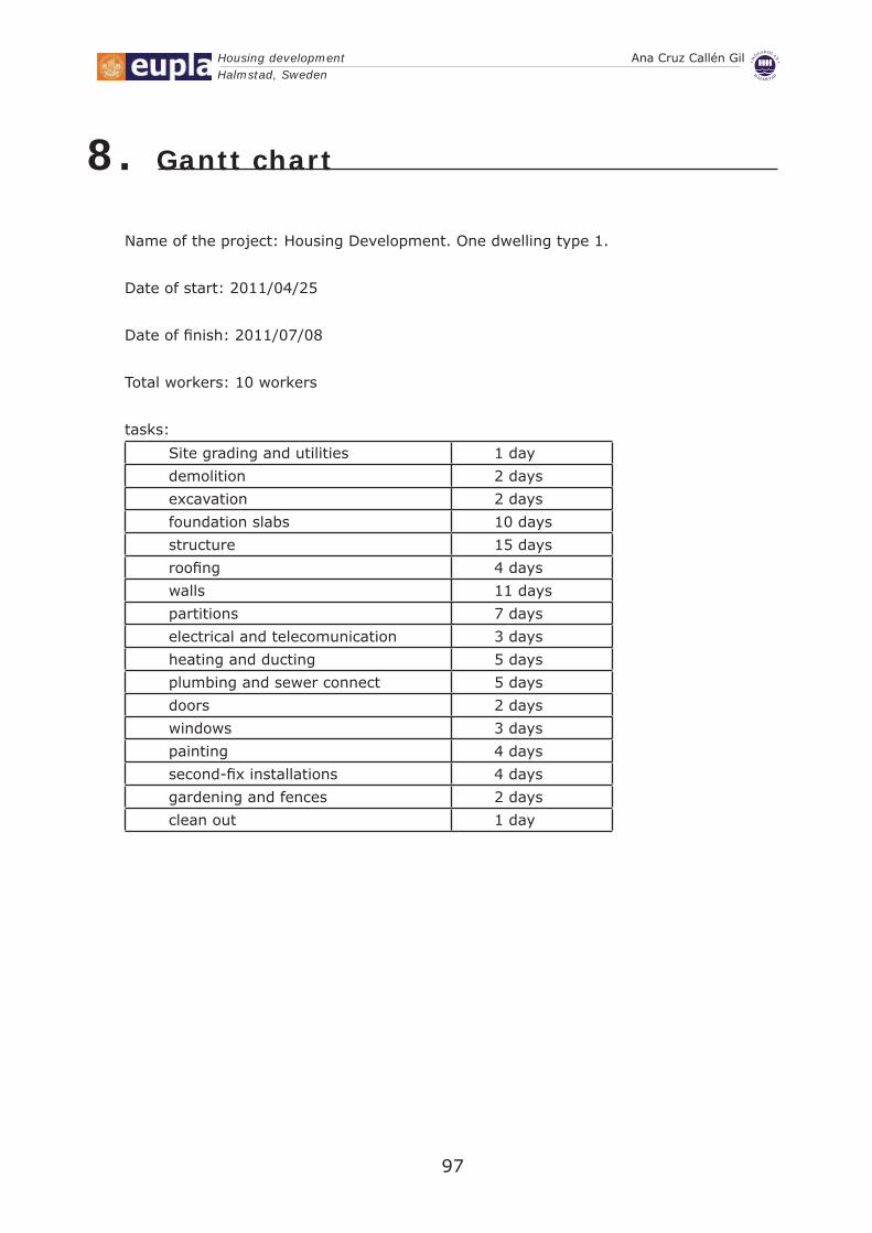
Housing development Ana Cruz Callén GilHalmstad, Sweden
97
Gantt chart8.
Name of the project: Housing Development. One dwelling type 1.
Date of start: 2011/04/25
Date of fi nish: 2011/07/08
Total workers: 10 workers
tasks:
Site grading and utilities 1 day
demolition 2 days
excavation 2 days
foundation slabs 10 days
structure 15 days
roofi ng 4 days
walls 11 days
partitions 7 days
electrical and telecomunication 3 days
heating and ducting 5 days
plumbing and sewer connect 5 days
doors 2 days
windows 3 days
painting 4 days
second-fi x installations 4 days
gardening and fences 2 days
clean out 1 day

Housing development Ana Cruz Callén GilHalmstad, Sweden
98
IDTa
sk N
ame
1Site
gra
din
g a
nd u
tilit
ies
2dem
olit
ion
3ex
cava
tion
4fo
undat
ion s
labs
5st
ruct
ure
6ro
ofing
7w
alls
8par
titions
9el
ectr
ical
and t
elec
om
unic
atio
n10
hea
ting a
nd d
uct
ing
11plu
mbin
g a
nd s
ewer
connec
t12
doors
13w
indow
s14
pai
nting
15se
cond-f
ix inst
alla
tions
16gar
den
ing a
nd f
ence
s17
clea
n o
ut
MF
TS
WS
TM
FT
SW
ST
MF
TS
WS
TM
18 A
pr '1
102
May
'11
16 M
ay '1
130
May
'11
13 J
un '1
127
Jun
'11
11 J
Task
Spl
it
Pro
gres
s
Mile
ston
e
Sum
mar
y
Pro
ject
Sum
mar
y
Ext
erna
l Tas
ks
Ext
erna
l Mile
ston
e
Dea
dlin
e
DW
ELL
ING
TY
PE
1 in
Hal
mst
ad, S
wed
en.
Pag
e 1
Pro
ject
: DW
ELL
ING
1.m
ppD
ate:
Wed
27/
04/1
1


100
Budget

Housing development Ana Cruz Callén GilHalmstad, Sweden
101
Budget9.

BUDGET SUMMARY CHAPTER RESUME EUROS %
CAP 01 SITE GRADING AND UTILITIES................................................................................................................... 19.191,90 7,41CAP 02 DEMOLITION............................................................................................................................................... 721,37 0,28CAP 03 FOUNDATION............................................................................................................................................. 13.547,54 5,23CAP 04 STRUCTURE............................................................................................................................................... 120.927,61 46,68CAP 05 ROOF......................................................................................................................................................... 49.073,70 18,94CAP 06 PARTITIONS............................................................................................................................................... 22.706,09 8,76CAP 07 EQUIPMENT................................................................................................................................................ 2.142,05 0,83CAP 08 COATINGS................................................................................................................................................. 3.215,35 1,24CAP 09 STAIRS...................................................................................................................................................... 6.304,58 2,43CAP 10 WINDOWS.................................................................................................................................................. 1.806,97 0,70CAP 11 INSTALLATIONS........................................................................................................................................ 7.978,49 3,08CAP 12 DOORS...................................................................................................................................................... 4.519,49 1,74CAP 13 EXTERIOR WORKS.................................................................................................................................... 6.922,88 2,67
TOTAL EJECUCIÓN MATERIAL 259.058,0213,00% Gastos generales .................... 33.677,546,00% Beneficio industrial................... 15.543,48
SUMA DE G.G. y B.I. 49.221,02
16,00% I.V.A..................................................................... 49.324,65
TOTAL BUDGET OF CONTRACT 357.603,69
TOTAL BUDGET 357.603,69
General budget is THREE HUNDRED FIFTY SEVEN THOUSAND SIX HUNDRED THREE EUROS with SIXTY NINECÉNTIMOS
27 de abril de 2011 Página 1
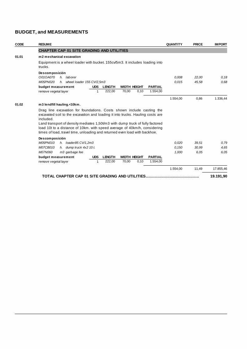
BUDGET, and MEASUREMENTS CODE RESUME QUANTITY PRICE IMPORT
CHAPTER CAP 01 SITE GRADING AND UTILITIES 01.01 m2 mechanical excavation
Equipment is a wheel loader with bucket. 155cv/5m3. It includes loading intotrucks.
DescomposiciónO01OA070 h. laborer 0,008 22,00 0,18M05PN020 h. wheel loader 155 CV/2,5m3 0,015 45,58 0,68budget measurement UDS LENGTH WIDTH HEIGHT PARTIALremove vegetal layer 1 222,00 70,00 0,10 1.554,00
1.554,00 0,86 1.336,44
01.02 m3 lendfill hauling.<10km.
Drag line excavation for foundations. Costs shown include casting theexcavated soil to the excavation and loading it into trucks. Hauling costs areincluded.Land transport of density mediates 1,50t/m3 with dump truck of fully factoredload 10t to a distance of 10km. with speed average of 40km/h, consideringtimes of load, travel time, unloading and returned even load with backhoe.
DescomposiciónM05PN010 h. loader85 CV/1,2m3 0,020 39,51 0,79M07CB010 h. dump truck 4x2 10 t. 0,150 30,99 4,65M07N060 m3 garbage fee 1,000 6,05 6,05budget measurement UDS LENGTH WIDTH HEIGHT PARTIALremove vegetal layer 1 222,00 70,00 0,10 1.554,00
1.554,00 11,49 17.855,46
TOTAL CHAPTER CAP 01 SITE GRADING AND UTILITIES............................................. 19.191,90
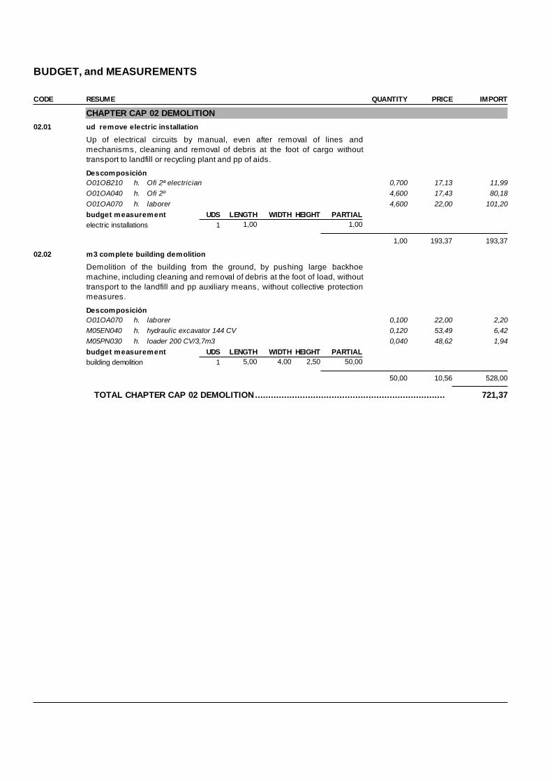
BUDGET, and MEASUREMENTS CODE RESUME QUANTITY PRICE IMPORT
CHAPTER CAP 02 DEMOLITION 02.01 ud remove electric installation
Up of electrical circuits by manual, even after removal of lines andmechanisms, cleaning and removal of debris at the foot of cargo withouttransport to landfill or recycling plant and pp of aids.
DescomposiciónO01OB210 h. Ofi 2ª electrician 0,700 17,13 11,99O01OA040 h. Ofi 2º 4,600 17,43 80,18O01OA070 h. laborer 4,600 22,00 101,20budget measurement UDS LENGTH WIDTH HEIGHT PARTIALelectric installations 1 1,00 1,00
1,00 193,37 193,37
02.02 m3 complete building demolition
Demolition of the building from the ground, by pushing large backhoemachine, including cleaning and removal of debris at the foot of load, withouttransport to the landfill and pp auxiliary means, without collective protectionmeasures.
DescomposiciónO01OA070 h. laborer 0,100 22,00 2,20M05EN040 h. hydraulic excavator 144 CV 0,120 53,49 6,42M05PN030 h. loader 200 CV/3,7m3 0,040 48,62 1,94budget measurement UDS LENGTH WIDTH HEIGHT PARTIALbuilding demolition 1 5,00 4,00 2,50 50,00
50,00 10,56 528,00
TOTAL CHAPTER CAP 02 DEMOLITION........................................................................ 721,37
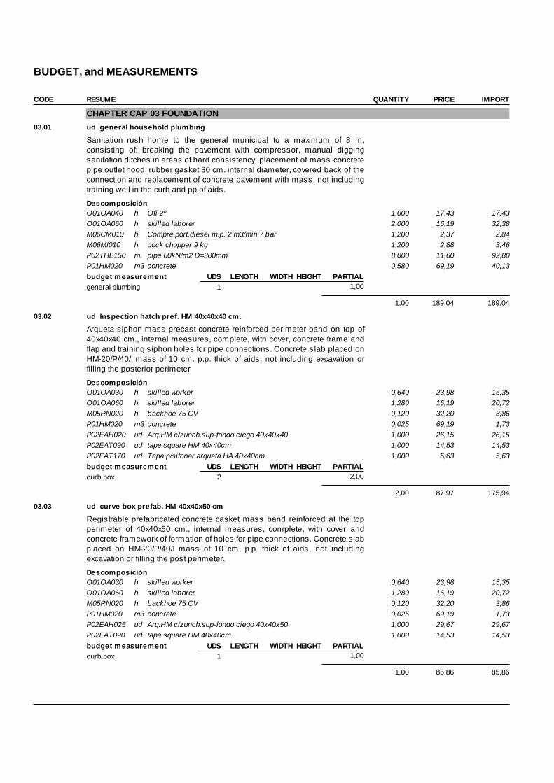
BUDGET, and MEASUREMENTS CODE RESUME QUANTITY PRICE IMPORT
CHAPTER CAP 03 FOUNDATION 03.01 ud general household plumbing
Sanitation rush home to the general municipal to a maximum of 8 m,consisting of: breaking the pavement with compressor, manual diggingsanitation ditches in areas of hard consistency, placement of mass concretepipe outlet hood, rubber gasket 30 cm. internal diameter, covered back of theconnection and replacement of concrete pavement with mass, not includingtraining well in the curb and pp of aids.
DescomposiciónO01OA040 h. Ofi 2º 1,000 17,43 17,43O01OA060 h. skilled laborer 2,000 16,19 32,38M06CM010 h. Compre.port.diesel m.p. 2 m3/min 7 bar 1,200 2,37 2,84M06MI010 h. cock chopper 9 kg 1,200 2,88 3,46P02THE150 m. pipe 60kN/m2 D=300mm 8,000 11,60 92,80P01HM020 m3 concrete 0,580 69,19 40,13budget measurement UDS LENGTH WIDTH HEIGHT PARTIALgeneral plumbing 1 1,00
1,00 189,04 189,04
03.02 ud Inspection hatch pref. HM 40x40x40 cm.
Arqueta siphon mass precast concrete reinforced perimeter band on top of40x40x40 cm., internal measures, complete, with cover, concrete frame andflap and training siphon holes for pipe connections. Concrete slab placed onHM-20/P/40/I mass of 10 cm. p.p. thick of aids, not including excavation orfilling the posterior perimeter
DescomposiciónO01OA030 h. skilled worker 0,640 23,98 15,35O01OA060 h. skilled laborer 1,280 16,19 20,72M05RN020 h. backhoe 75 CV 0,120 32,20 3,86P01HM020 m3 concrete 0,025 69,19 1,73P02EAH020 ud Arq.HM c/zunch.sup-fondo ciego 40x40x40 1,000 26,15 26,15P02EAT090 ud tape square HM 40x40cm 1,000 14,53 14,53P02EAT170 ud Tapa p/sifonar arqueta HA 40x40cm 1,000 5,63 5,63budget measurement UDS LENGTH WIDTH HEIGHT PARTIALcurb box 2 2,00
2,00 87,97 175,94
03.03 ud curve box prefab. HM 40x40x50 cm
Registrable prefabricated concrete casket mass band reinforced at the topperimeter of 40x40x50 cm., internal measures, complete, with cover andconcrete framework of formation of holes for pipe connections. Concrete slabplaced on HM-20/P/40/I mass of 10 cm. p.p. thick of aids, not includingexcavation or filling the post perimeter.
DescomposiciónO01OA030 h. skilled worker 0,640 23,98 15,35O01OA060 h. skilled laborer 1,280 16,19 20,72M05RN020 h. backhoe 75 CV 0,120 32,20 3,86P01HM020 m3 concrete 0,025 69,19 1,73P02EAH025 ud Arq.HM c/zunch.sup-fondo ciego 40x40x50 1,000 29,67 29,67P02EAT090 ud tape square HM 40x40cm 1,000 14,53 14,53budget measurement UDS LENGTH WIDTH HEIGHT PARTIALcurb box 1 1,00
1,00 85,86 85,86

BUDGET, and MEASUREMENTS CODE RESUME QUANTITY PRICE IMPORT
03.04 m2 expanded polyestyrene panel PST+concrete.
Insulation in floors and improved to 31 dB noise impact by PST panel. ofIsover, placing the panels butt welded together and sockets perimeter of 6cm. in partitions, sealing all joints of panels and sockets, prior to pouring themortar slab mesh for execution., consisting of concrete HA-25/P/20/I, i / ppCutting, placement, mesh, concrete pouring and troweling and aids. Readyto receive any type of pavement (not included).
DescomposiciónO01OA030 h. skilled worker 0,120 23,98 2,88O01OA050 h. assistant 0,120 16,83 2,02P07AL350 m2 high density panel 1,150 7,28 8,37E04SE090 m3 concrete slab 0,040 103,38 4,14P03AM020 m2 mesh 15x15x5 2,078 kg/m2 1,000 1,25 1,25budget measurement UDS LENGTH WIDTH HEIGHT PARTIALconcrete slab 1 19,70 11,00 216,70
216,70 18,66 4.043,62
03.05 m2 expanded polyestyrene panel PST
Improving insulation and noise of 22 dBA to impact on intermediate floors, toimplement appropriate leveling layer, absorbing and removing any existingirregularities greater than 4 mm., being dry, flooring panels butt Isover PST,sealing joints with plastic tape and installation of laminated flooring directly, i/ pp Cutting, placement, support facilities and indirect costs.
DescomposiciónO01OA030 h. skilled worker 0,120 23,98 2,88O01OA050 h. assistant 0,120 16,83 2,02P07AL350 m2 high density panel 1,150 7,28 8,37P07W350 ud adhesive 0,020 1,69 0,03budget measurement UDS LENGTH WIDTH HEIGHT PARTIALconcrete slab 2 19,70 11,00 433,40
433,40 13,30 5.764,22
03.06 m2 extruded polyestyrene XPS.
Floor insulation, using extruded polystyrene rigid plates of Ursa NIII I XPS of10 mm. thick, even p.p. cutting and placemen
DescomposiciónO01OA030 h. skilled worker 0,050 23,98 1,20O01OA050 h. assistant 0,050 16,83 0,84P07TX315 m2 P.pol.extr.Ursa XPS NIII I 10mm. 1,050 9,90 10,40budget measurement UDS LENGTH WIDTH HEIGHT PARTIALsolera de hormigon 1 19,70 11,00 216,70
216,70 12,44 2.695,75
03.07 m2 geotextile
Supply and installation of punched polyester geotextile with a weight of 200g/m2 and <38 mm. Opening in Dynamic perforation test, extended on theground with overlaps of 10 cm., for subsequent filling with earth.
DescomposiciónO01OA070 h. laborer 0,010 22,00 0,22P06BG060 m2 Fieltro geotextil Danofelt PY-200 gr/m2 1,100 0,60 0,66budget measurement UDS LENGTH WIDTH HEIGHT PARTIALconcrete slab 1 19,70 11,00 216,70
216,70 0,88 190,70

BUDGET, and MEASUREMENTS CODE RESUME QUANTITY PRICE IMPORT
03.08 m3 gravel
Filling, spreading and compacting graded aggregates open by mechanicalmeans, in tiers of 30 cm. thick, to achieve a degree of compaction of 95% ofnormal proctor, including watering and refining the same slope, and pp ofaids, considering the pit walk graded aggregates ..
DescomposiciónO01OA070 h. laborer 0,085 22,00 1,87P01AF040 t. Zahorra artifici. huso Z-3 DA<25 1,700 6,26 10,64M08NM020 h. Motoniveladora de 200 CV 0,015 71,55 1,07M08RN020 h. vibrant roller autopropuls.mixto 7 t. 0,095 45,78 4,35M08CA110 h. Cisterna agua s/camión 10.000 l. 0,020 32,01 0,64budget measurement UDS LENGTH WIDTH HEIGHT PARTIALconcrete slab 1 19,70 11,00 0,10 21,67
21,67 18,57 402,41
TOTAL CHAPTER CAP 03 FOUNDATION....................................................................... 13.547,54
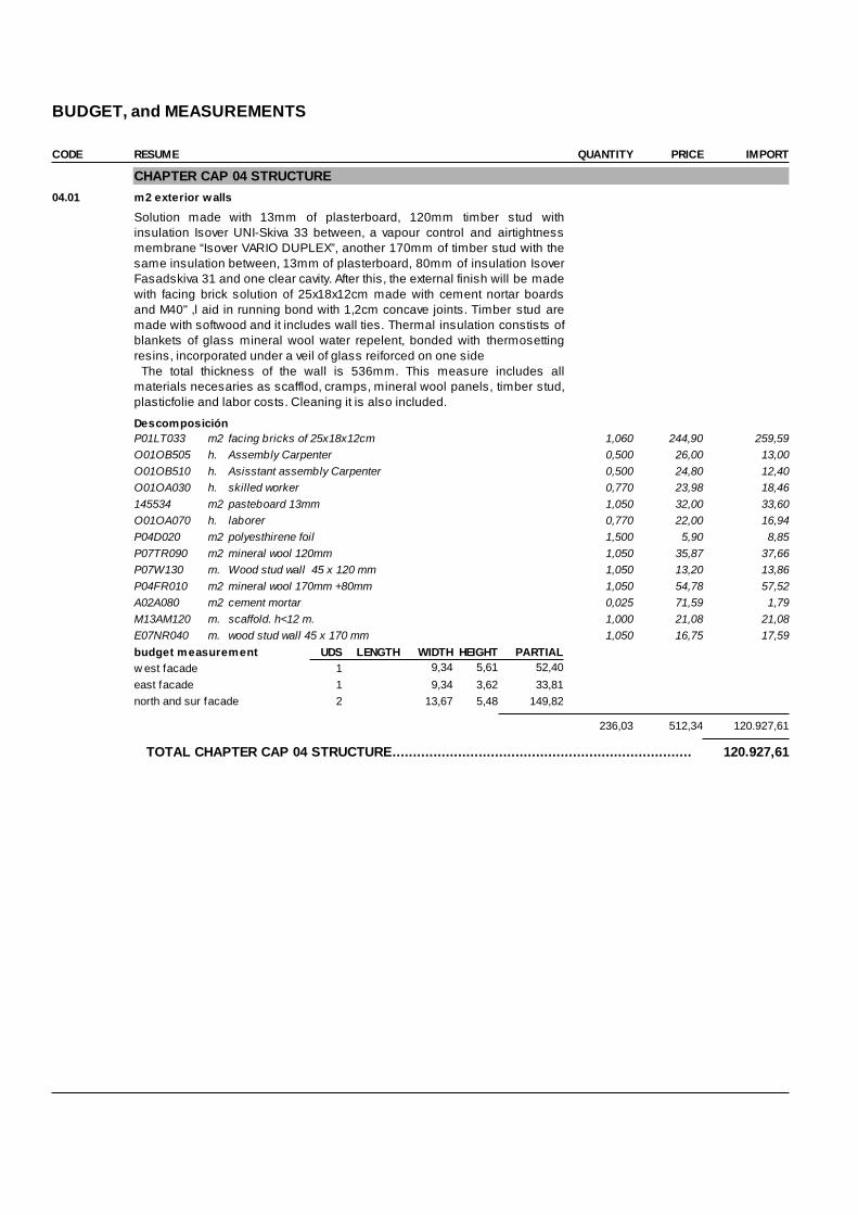
BUDGET, and MEASUREMENTS CODE RESUME QUANTITY PRICE IMPORT
CHAPTER CAP 04 STRUCTURE 04.01 m2 exterior walls
Solution made with 13mm of plasterboard, 120mm timber stud withinsulation Isover UNI-Skiva 33 between, a vapour control and airtightnessmembrane “Isover VARIO DUPLEX”, another 170mm of timber stud with thesame insulation between, 13mm of plasterboard, 80mm of insulation IsoverFasadskiva 31 and one clear cavity. After this, the external finish will be madewith facing brick solution of 25x18x12cm made with cement nortar boardsand M40" ,l aid in running bond with 1,2cm concave joints. Timber stud aremade with softwood and it includes wall ties. Thermal insulation constists ofblankets of glass mineral wool water repelent, bonded with thermosettingresins, incorporated under a veil of glass reiforced on one side The total thickness of the wall is 536mm. This measure includes allmaterials necesaries as scafflod, cramps, mineral wool panels, timber stud,plasticfolie and labor costs. Cleaning it is also included.
DescomposiciónP01LT033 m2 facing bricks of 25x18x12cm 1,060 244,90 259,59O01OB505 h. Assembly Carpenter 0,500 26,00 13,00O01OB510 h. Asisstant assembly Carpenter 0,500 24,80 12,40O01OA030 h. skilled worker 0,770 23,98 18,46145534 m2 pasteboard 13mm 1,050 32,00 33,60O01OA070 h. laborer 0,770 22,00 16,94P04D020 m2 polyesthirene foil 1,500 5,90 8,85P07TR090 m2 mineral wool 120mm 1,050 35,87 37,66P07W130 m. Wood stud wall 45 x 120 mm 1,050 13,20 13,86P04FR010 m2 mineral wool 170mm +80mm 1,050 54,78 57,52A02A080 m2 cement mortar 0,025 71,59 1,79M13AM120 m. scaffold. h<12 m. 1,000 21,08 21,08E07NR040 m. wood stud wall 45 x 170 mm 1,050 16,75 17,59budget measurement UDS LENGTH WIDTH HEIGHT PARTIALw est facade 1 9,34 5,61 52,40east facade 1 9,34 3,62 33,81north and sur facade 2 13,67 5,48 149,82
236,03 512,34 120.927,61
TOTAL CHAPTER CAP 04 STRUCTURE......................................................................... 120.927,61
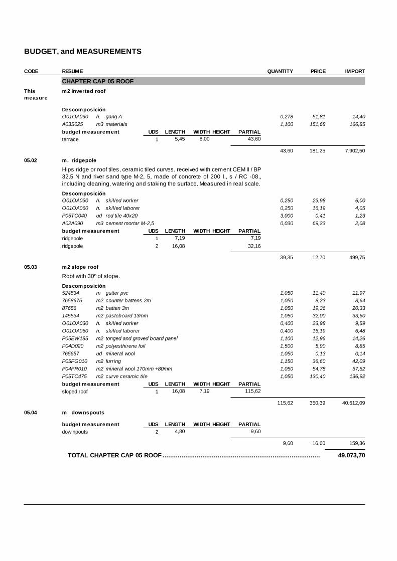
BUDGET, and MEASUREMENTS CODE RESUME QUANTITY PRICE IMPORT
CHAPTER CAP 05 ROOF Thismeasure
m2 inverted roof
DescomposiciónO01OA090 h. gang A 0,278 51,81 14,40A03S025 m3 materials 1,100 151,68 166,85budget measurement UDS LENGTH WIDTH HEIGHT PARTIALterrace 1 5,45 8,00 43,60
43,60 181,25 7.902,50
05.02 m. ridgepole
Hips ridge or roof tiles, ceramic tiled curves, received with cement CEM II / BP32.5 N and river sand type M-2, 5, made of concrete of 200 l., s / RC -08.,including cleaning, watering and staking the surface. Measured in real scale.
DescomposiciónO01OA030 h. skilled worker 0,250 23,98 6,00O01OA060 h. skilled laborer 0,250 16,19 4,05P05TC040 ud red tile 40x20 3,000 0,41 1,23A02A090 m3 cement mortar M-2,5 0,030 69,23 2,08budget measurement UDS LENGTH WIDTH HEIGHT PARTIALridgepole 1 7,19 7,19ridgepole 2 16,08 32,16
39,35 12,70 499,75
05.03 m2 slope roof
Roof with 30º of slope.
Descomposición524534 m gutter pvc 1,050 11,40 11,977658675 m2 counter battens 2m 1,050 8,23 8,6487656 m2 batten 3m 1,050 19,36 20,33145534 m2 pasteboard 13mm 1,050 32,00 33,60O01OA030 h. skilled worker 0,400 23,98 9,59O01OA060 h. skilled laborer 0,400 16,19 6,48P05EW185 m2 tonged and groved board panel 1,100 12,96 14,26P04D020 m2 polyesthirene foil 1,500 5,90 8,85765657 ud mineral wool 1,050 0,13 0,14P05FG010 m2 furring 1,150 36,60 42,09P04FR010 m2 mineral wool 170mm +80mm 1,050 54,78 57,52P05TC475 m2 curve ceramic tile 1,050 130,40 136,92budget measurement UDS LENGTH WIDTH HEIGHT PARTIALsloped roof 1 16,08 7,19 115,62
115,62 350,39 40.512,09
05.04 m downspouts
budget measurement UDS LENGTH WIDTH HEIGHT PARTIALdow npouts 2 4,80 9,60
9,60 16,60 159,36
TOTAL CHAPTER CAP 05 ROOF ................................................................................... 49.073,70

BUDGET, and MEASUREMENTS CODE RESUME QUANTITY PRICE IMPORT
CHAPTER CAP 06 PARTITIONS 06.01 m2 inner walls
Costs are per square meter of wall, measured on one face. It is ready topaint.Inner partitions will be made in general with prefabricated panels. Thispartitions will be composed by a solution made with 13mm of plasterboard,95mm timber stud with insulation Isover ULTIMATE UNI-Skiva 37 betweenand 13mm of thickness of plasterboard. The partition will be mountedthrough horizontal base screed and vertical every 60cm.ENT
Descomposición12344 m2 mineral wool 80mm 1,050 30,10 31,61O01OA030 h. skilled worker 0,350 23,98 8,39O01OA050 h. assistant 0,350 16,83 5,89145534 m2 pasteboard 13mm 2,050 32,00 65,60P04SC280 m wood stud 45x95mm 3,500 35,79 125,27P05CW030 ud accesories 0,500 0,50 0,25M13W210 h. elevation machinery 0,150 61,73 9,26budget measurement UDS LENGTH WIDTH HEIGHT PARTIALf irst f lloor 1 11,59 3,20 37,09ground f loor 1 20,41 2,70 55,11
92,20 246,27 22.706,09
TOTAL CHAPTER CAP 06 PARTITIONS......................................................................... 22.706,09

BUDGET, and MEASUREMENTS CODE RESUME QUANTITY PRICE IMPORT
CHAPTER CAP 07 EQUIPMENT 07.01 ud sanitaries
.
DescomposiciónE21ADC040 ud shower 195x90cm 1,000 201,00 201,00E21ABC036 ud Bathtub white 170x70cm 1,000 207,66 207,66E21ADA020 ud shower.90x90cm 1,000 255,20 255,20E21SRM020 ud white sink 120x60cm 3,000 196,63 589,89E21SRM030 ud white wc 3,000 296,10 888,30
1,00 2.142,05 2.142,05
TOTAL CHAPTER CAP 07 EQUIPMENT.......................................................................... 2.142,05
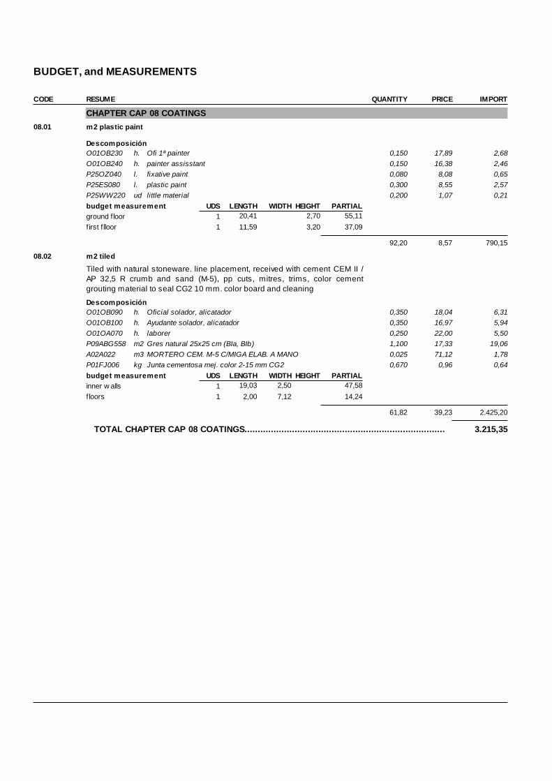
BUDGET, and MEASUREMENTS CODE RESUME QUANTITY PRICE IMPORT
CHAPTER CAP 08 COATINGS 08.01 m2 plastic paint
DescomposiciónO01OB230 h. Ofi 1ª painter 0,150 17,89 2,68O01OB240 h. painter assisstant 0,150 16,38 2,46P25OZ040 l. fixative paint 0,080 8,08 0,65P25ES080 l. plastic paint 0,300 8,55 2,57P25WW220 ud little material 0,200 1,07 0,21budget measurement UDS LENGTH WIDTH HEIGHT PARTIALground f loor 1 20,41 2,70 55,11first f lloor 1 11,59 3,20 37,09
92,20 8,57 790,15
08.02 m2 tiled
Tiled with natural stoneware. line placement, received with cement CEM II /AP 32,5 R crumb and sand (M-5), pp cuts, mitres, trims, color cementgrouting material to seal CG2 10 mm. color board and cleaning
DescomposiciónO01OB090 h. Oficial solador, alicatador 0,350 18,04 6,31O01OB100 h. Ayudante solador, alicatador 0,350 16,97 5,94O01OA070 h. laborer 0,250 22,00 5,50P09ABG558 m2 Gres natural 25x25 cm (BIa, BIb) 1,100 17,33 19,06A02A022 m3 MORTERO CEM. M-5 C/MIGA ELAB. A MANO 0,025 71,12 1,78P01FJ006 kg Junta cementosa mej. color 2-15 mm CG2 0,670 0,96 0,64budget measurement UDS LENGTH WIDTH HEIGHT PARTIALinner w alls 1 19,03 2,50 47,58floors 1 2,00 7,12 14,24
61,82 39,23 2.425,20
TOTAL CHAPTER CAP 08 COATINGS............................................................................ 3.215,35
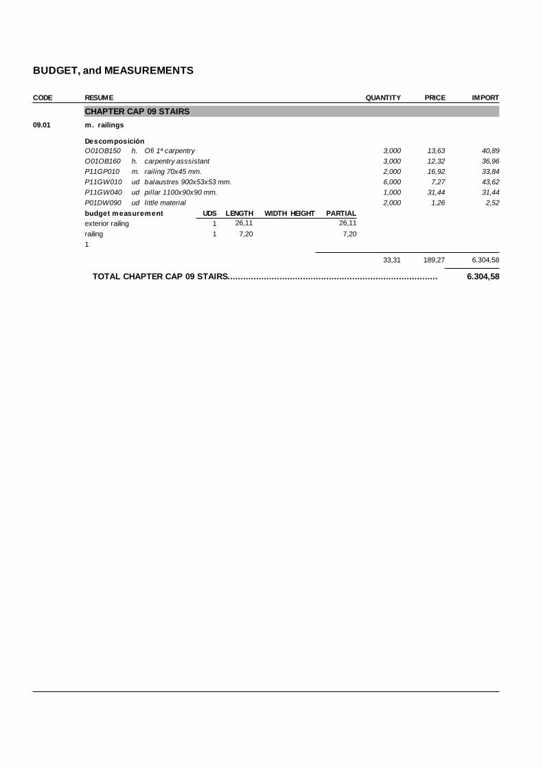
BUDGET, and MEASUREMENTS CODE RESUME QUANTITY PRICE IMPORT
CHAPTER CAP 09 STAIRS 09.01 m. railings
DescomposiciónO01OB150 h. Ofi 1ª carpentry 3,000 13,63 40,89O01OB160 h. carpentry asssistant 3,000 12,32 36,96P11GP010 m. railing 70x45 mm. 2,000 16,92 33,84P11GW010 ud balaustres 900x53x53 mm. 6,000 7,27 43,62P11GW040 ud pillar 1100x90x90 mm. 1,000 31,44 31,44P01DW090 ud little material 2,000 1,26 2,52budget measurement UDS LENGTH WIDTH HEIGHT PARTIALexterior railing 1 26,11 26,11railing 1 7,20 7,201
33,31 189,27 6.304,58
TOTAL CHAPTER CAP 09 STAIRS................................................................................. 6.304,58
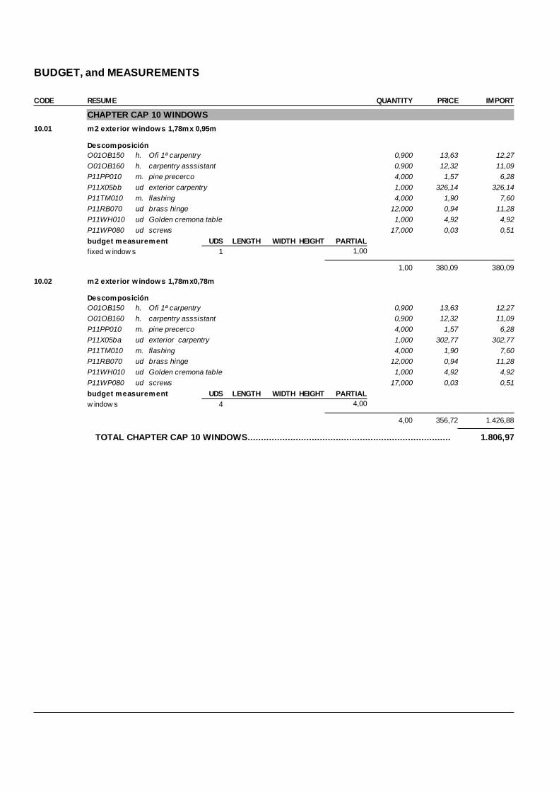
BUDGET, and MEASUREMENTS CODE RESUME QUANTITY PRICE IMPORT
CHAPTER CAP 10 WINDOWS 10.01 m2 exterior w indows 1,78mx 0,95m
DescomposiciónO01OB150 h. Ofi 1ª carpentry 0,900 13,63 12,27O01OB160 h. carpentry asssistant 0,900 12,32 11,09P11PP010 m. pine precerco 4,000 1,57 6,28P11X05bb ud exterior carpentry 1,000 326,14 326,14P11TM010 m. flashing 4,000 1,90 7,60P11RB070 ud brass hinge 12,000 0,94 11,28P11WH010 ud Golden cremona table 1,000 4,92 4,92P11WP080 ud screws 17,000 0,03 0,51budget measurement UDS LENGTH WIDTH HEIGHT PARTIALf ixed w indow s 1 1,00
1,00 380,09 380,09
10.02 m2 exterior w indows 1,78mx0,78m
DescomposiciónO01OB150 h. Ofi 1ª carpentry 0,900 13,63 12,27O01OB160 h. carpentry asssistant 0,900 12,32 11,09P11PP010 m. pine precerco 4,000 1,57 6,28P11X05ba ud exterior carpentry 1,000 302,77 302,77P11TM010 m. flashing 4,000 1,90 7,60P11RB070 ud brass hinge 12,000 0,94 11,28P11WH010 ud Golden cremona table 1,000 4,92 4,92P11WP080 ud screws 17,000 0,03 0,51budget measurement UDS LENGTH WIDTH HEIGHT PARTIALw indow s 4 4,00
4,00 356,72 1.426,88
TOTAL CHAPTER CAP 10 WINDOWS............................................................................ 1.806,97

BUDGET, and MEASUREMENTS CODE RESUME QUANTITY PRICE IMPORT
CHAPTER CAP 11 INSTALLATIONS 11.01 ud heating and warm water
In a two-pipe system, steam supply to the heating units and condensatereturn from heating units are through separate pipes. Air accumulation inpiping and heating units discharges from the system through the open venton the condensate pump receiver. Piping and heating units will be installedwith proper pitch to provide gravity flow of all condensate to the pumpreceiver.Warm water distribution will be made with electrolytic copper pipe withmeetings welded, in dimensions and diameters according to plane ofproject. It will be installed, verified and measured according to regulation.
DescomposiciónO01OB170 h. Ofil 1ª plumber 46,000 19,07 877,22O01OB180 h. Ofi 2ª plumber 46,000 17,37 799,02P20RA170 ud thermostat 220 V. 1,000 32,64 32,64P20WH010 m. chimney vent D=150 mm. 8,000 70,26 562,08P20WH060 ud elbow pipe. vent D=150 mm 2,000 44,68 89,36P20WH100 ud adapter exchanger D=150 mm 1,000 24,83 24,83P20DO020 ud heat exchanger 1,000 530,00 530,00P20MA030 ud aluminium element 126,000 13,80 1.738,80P20MW010 ud faucet 14,000 7,00 98,00P20MW020 ud automatic purger 14,000 0,94 13,16P20MW030 ud radiator support 30,000 0,80 24,00P17CH010 m. cooper pipe 10/12 mm. 135,000 2,86 386,10P17CH030 m. cooper pipe 16/18 mm. 70,000 4,32 302,40P17CH040 m. cooper pipe20/22 mm. 30,000 6,06 181,80P20TB020 m. PVC D=25 mm.i/acc. 135,000 0,95 128,25P20TB030 m. PVC D=32 mm.i/acc. 70,000 1,95 136,50P20TB040 m. PVC D=40 mm.i/acc. 30,000 2,98 89,40budget measurement UDS LENGTH WIDTH HEIGHT PARTIAL
1 1,00
1,00 6.013,56 6.013,56
11.02 ud ventilation system
Ventilation in the kitchens will be made by means of flexible lamina tube ofaluminium and polyester, mounted on steel thread spiral with non--flammable tube of rigid PVC of 120mm will arrange in addition an extractor tosmoke and gases, with centrifugal ventilator, of double aspiration and withsingle phase incorporated electrical motor, mounted with vibration-proofsystems and elastic connection in the mouth, with a power of 800 evacuationof m3/h. It will be demanded that the extractors have official certificate ofoperation.
DescomposiciónO01OB170 h. Ofil 1ª plumber 3,980 19,07 75,90E23MC090 m. PVC D=150 mm 8,000 32,98 263,84E23MC110 m. PVC D=120 mm 8,000 14,51 116,08E23MG010 ud extractor 4 mouths 1,000 151,68 151,68budget measurement UDS LENGTH WIDTH HEIGHT PARTIAL
1 1,00
1,00 607,50 607,50

BUDGET, and MEASUREMENTS CODE RESUME QUANTITY PRICE IMPORT
11.03 ud cold water
cold water distribution will be made with electrolytic copper pipe withmeetings welded, in dimensions and diameters according to plane ofproject. It will be installed, verified and measured according to regulation.
DescomposiciónE20XEC030 ud toilet 1,000 265,06 265,06E20XEC040 ud bathroom 2,000 392,00 784,00E20XEC050 ud kitchen 1,000 308,37 308,37budget measurement UDS LENGTH WIDTH HEIGHT PARTIAL
1 1,00
1,00 1.357,43 1.357,43
TOTAL CHAPTER CAP 11 INSTALLATIONS................................................................... 7.978,49
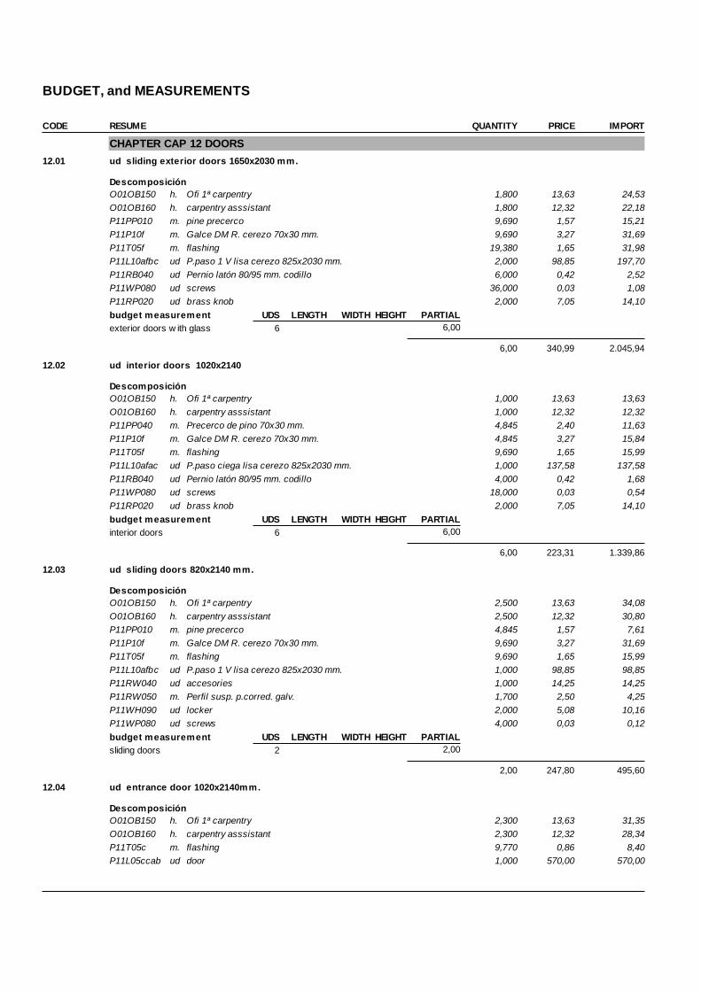
BUDGET, and MEASUREMENTS CODE RESUME QUANTITY PRICE IMPORT
CHAPTER CAP 12 DOORS 12.01 ud sliding exterior doors 1650x2030 mm.
DescomposiciónO01OB150 h. Ofi 1ª carpentry 1,800 13,63 24,53O01OB160 h. carpentry asssistant 1,800 12,32 22,18P11PP010 m. pine precerco 9,690 1,57 15,21P11P10f m. Galce DM R. cerezo 70x30 mm. 9,690 3,27 31,69P11T05f m. flashing 19,380 1,65 31,98P11L10afbc ud P.paso 1 V lisa cerezo 825x2030 mm. 2,000 98,85 197,70P11RB040 ud Pernio latón 80/95 mm. codillo 6,000 0,42 2,52P11WP080 ud screws 36,000 0,03 1,08P11RP020 ud brass knob 2,000 7,05 14,10budget measurement UDS LENGTH WIDTH HEIGHT PARTIALexterior doors w ith glass 6 6,00
6,00 340,99 2.045,94
12.02 ud interior doors 1020x2140
DescomposiciónO01OB150 h. Ofi 1ª carpentry 1,000 13,63 13,63O01OB160 h. carpentry asssistant 1,000 12,32 12,32P11PP040 m. Precerco de pino 70x30 mm. 4,845 2,40 11,63P11P10f m. Galce DM R. cerezo 70x30 mm. 4,845 3,27 15,84P11T05f m. flashing 9,690 1,65 15,99P11L10afac ud P.paso ciega lisa cerezo 825x2030 mm. 1,000 137,58 137,58P11RB040 ud Pernio latón 80/95 mm. codillo 4,000 0,42 1,68P11WP080 ud screws 18,000 0,03 0,54P11RP020 ud brass knob 2,000 7,05 14,10budget measurement UDS LENGTH WIDTH HEIGHT PARTIALinterior doors 6 6,00
6,00 223,31 1.339,86
12.03 ud sliding doors 820x2140 mm.
DescomposiciónO01OB150 h. Ofi 1ª carpentry 2,500 13,63 34,08O01OB160 h. carpentry asssistant 2,500 12,32 30,80P11PP010 m. pine precerco 4,845 1,57 7,61P11P10f m. Galce DM R. cerezo 70x30 mm. 9,690 3,27 31,69P11T05f m. flashing 9,690 1,65 15,99P11L10afbc ud P.paso 1 V lisa cerezo 825x2030 mm. 1,000 98,85 98,85P11RW040 ud accesories 1,000 14,25 14,25P11RW050 m. Perfil susp. p.corred. galv. 1,700 2,50 4,25P11WH090 ud locker 2,000 5,08 10,16P11WP080 ud screws 4,000 0,03 0,12budget measurement UDS LENGTH WIDTH HEIGHT PARTIALsliding doors 2 2,00
2,00 247,80 495,60
12.04 ud entrance door 1020x2140mm.
DescomposiciónO01OB150 h. Ofi 1ª carpentry 2,300 13,63 31,35O01OB160 h. carpentry asssistant 2,300 12,32 28,34P11T05c m. flashing 9,770 0,86 8,40P11L05ccab ud door 1,000 570,00 570,00

BUDGET, and MEASUREMENTS CODE RESUME QUANTITY PRICE IMPORT
budget measurement UDS LENGTH WIDTH HEIGHT PARTIALentrance door 1 1,00
1,00 638,09 638,09
TOTAL CHAPTER CAP 12 DOORS................................................................................. 4.519,49
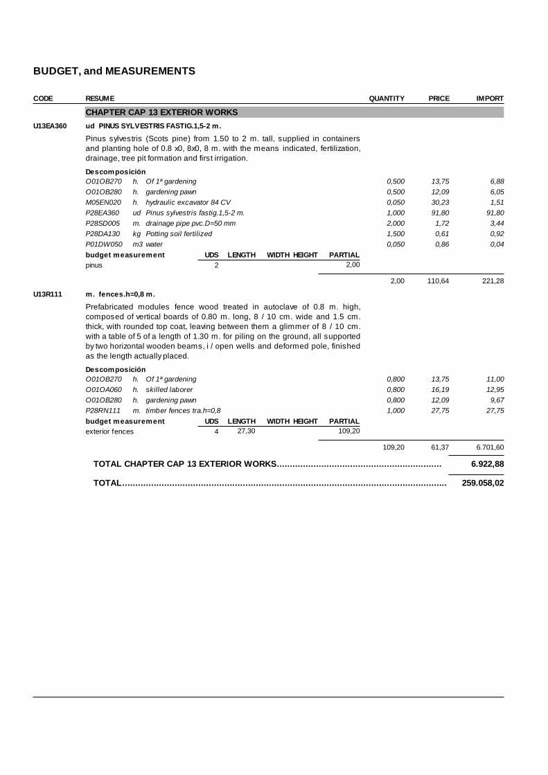
BUDGET, and MEASUREMENTS CODE RESUME QUANTITY PRICE IMPORT
CHAPTER CAP 13 EXTERIOR WORKS U13EA360 ud PINUS SYLVESTRIS FASTIG.1,5-2 m.
Pinus sylvestris (Scots pine) from 1.50 to 2 m. tall, supplied in containersand planting hole of 0.8 x0, 8x0, 8 m. with the means indicated, fertilization,drainage, tree pit formation and first irrigation.
DescomposiciónO01OB270 h. Of 1ª gardening 0,500 13,75 6,88O01OB280 h. gardening pawn 0,500 12,09 6,05M05EN020 h. hydraulic excavator 84 CV 0,050 30,23 1,51P28EA360 ud Pinus sylvestris fastig.1,5-2 m. 1,000 91,80 91,80P28SD005 m. drainage pipe pvc.D=50 mm 2,000 1,72 3,44P28DA130 kg Potting soil fertilized 1,500 0,61 0,92P01DW050 m3 water 0,050 0,86 0,04budget measurement UDS LENGTH WIDTH HEIGHT PARTIALpinus 2 2,00
2,00 110,64 221,28
U13R111 m. fences.h=0,8 m.
Prefabricated modules fence wood treated in autoclave of 0.8 m. high,composed of vertical boards of 0.80 m. long, 8 / 10 cm. wide and 1.5 cm.thick, with rounded top coat, leaving between them a glimmer of 8 / 10 cm.with a table of 5 of a length of 1.30 m. for piling on the ground, all supportedby two horizontal wooden beams, i / open wells and deformed pole, finishedas the length actually placed.
DescomposiciónO01OB270 h. Of 1ª gardening 0,800 13,75 11,00O01OA060 h. skilled laborer 0,800 16,19 12,95O01OB280 h. gardening pawn 0,800 12,09 9,67P28RN111 m. timber fences tra.h=0,8 1,000 27,75 27,75budget measurement UDS LENGTH WIDTH HEIGHT PARTIALexterior fences 4 27,30 109,20
109,20 61,37 6.701,60
TOTAL CHAPTER CAP 13 EXTERIOR WORKS............................................................... 6.922,88
TOTAL............................................................................................................................ 259.058,02

120
Pictures


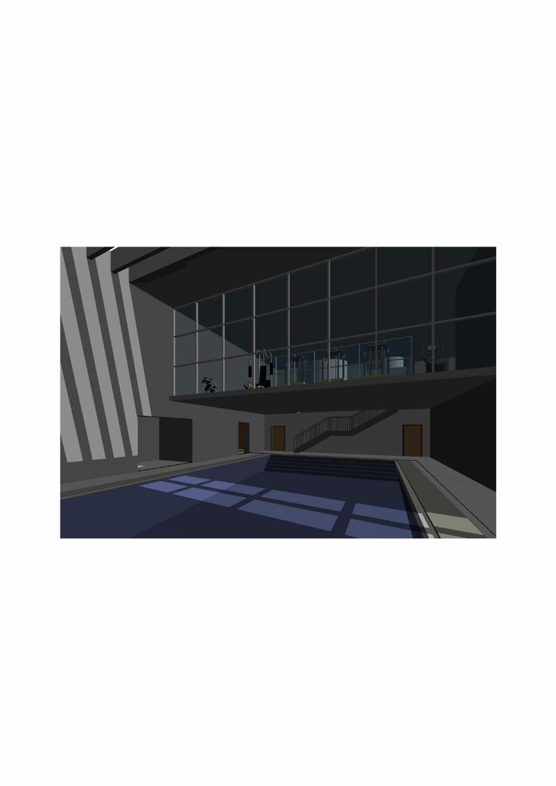

124
Drawings

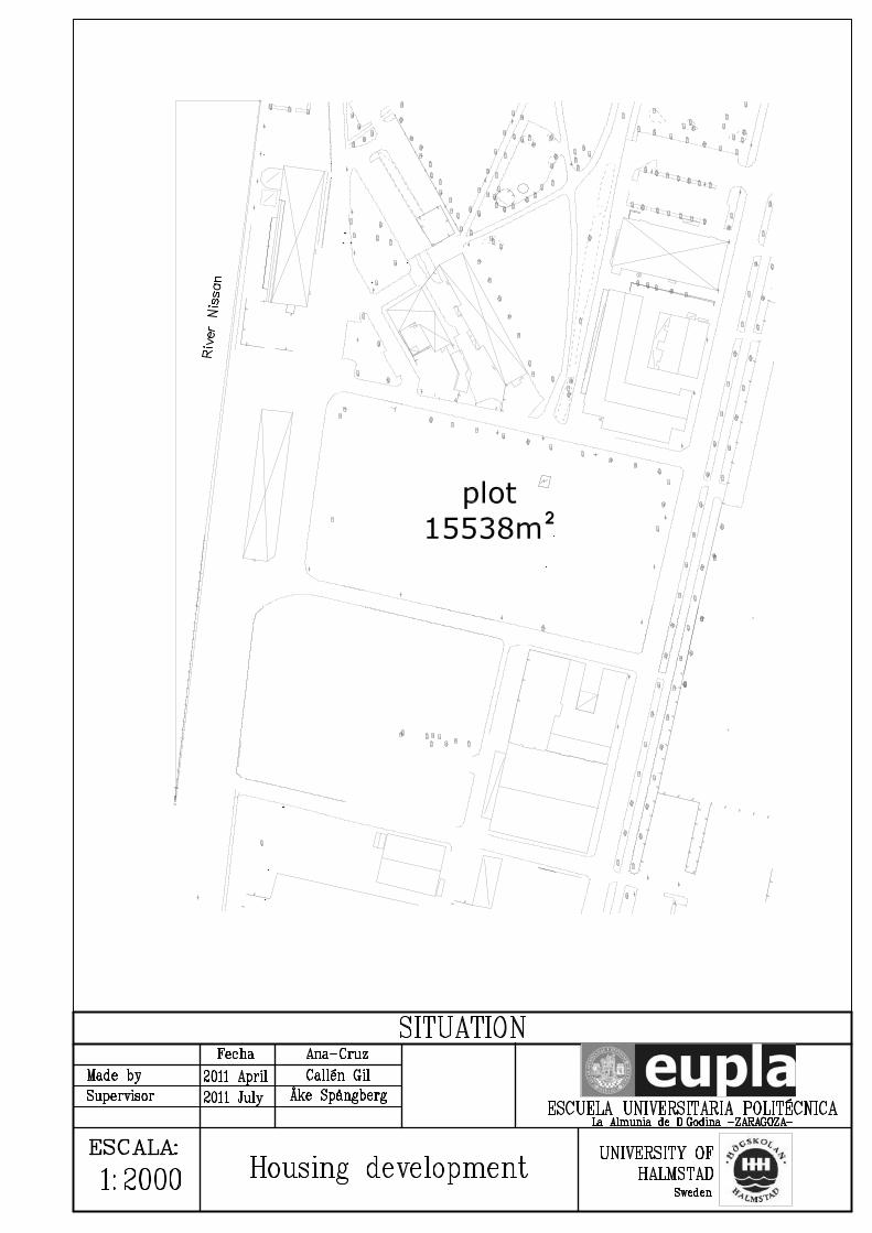
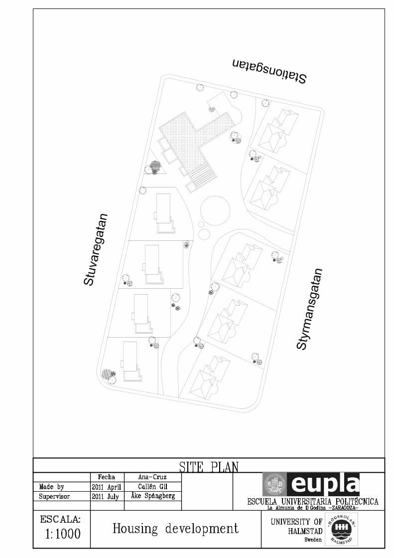
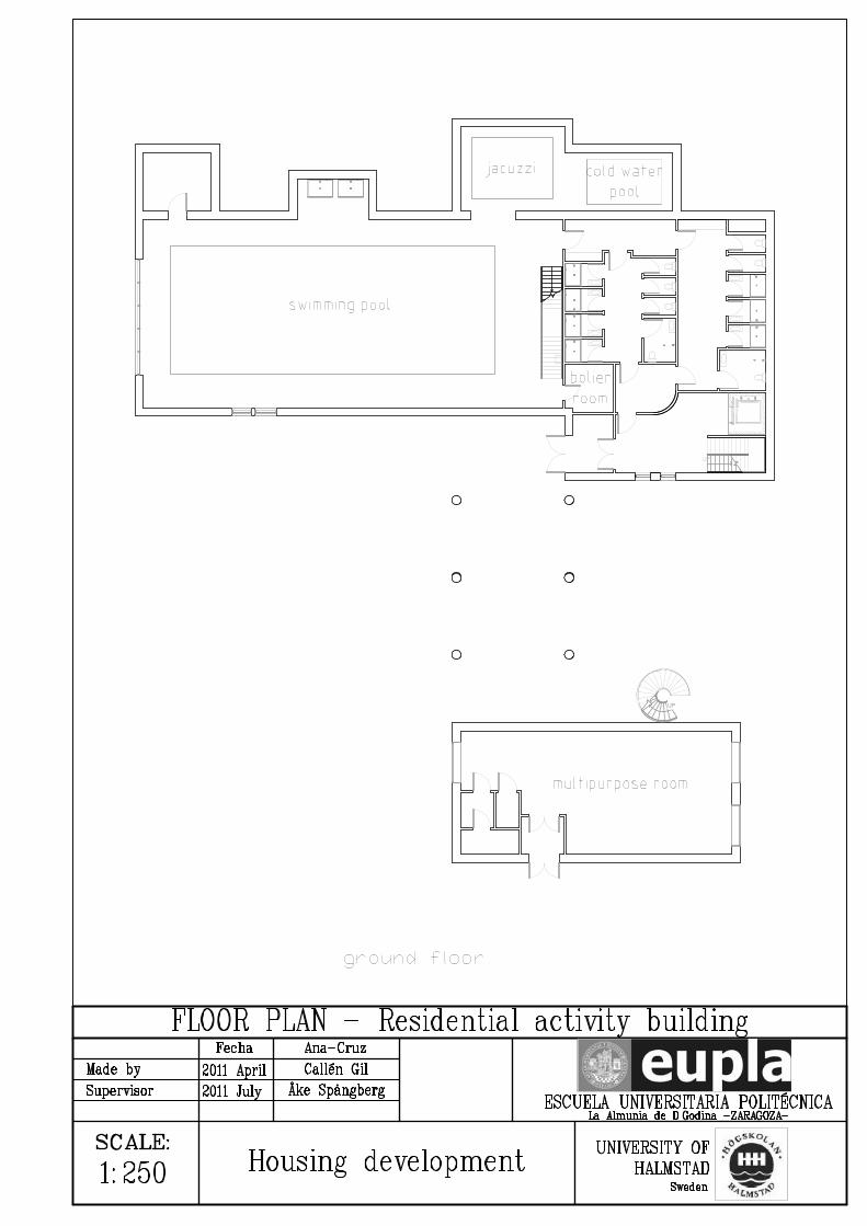
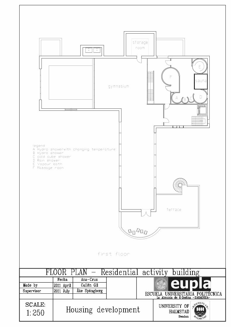
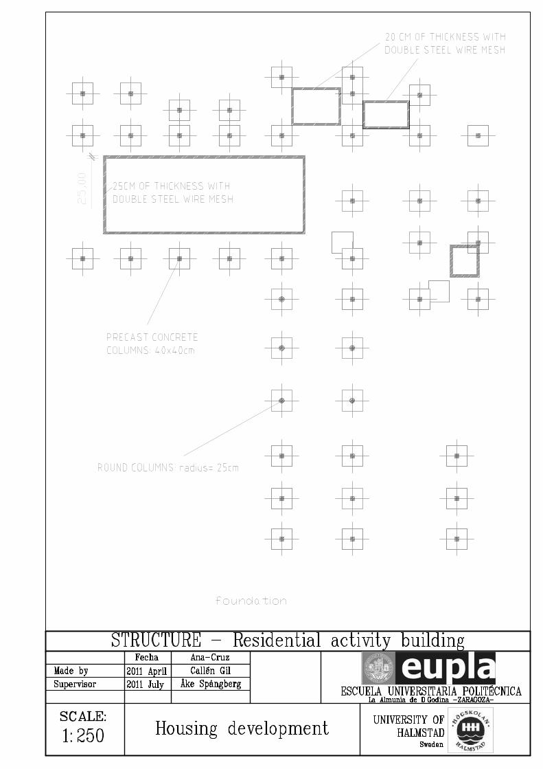
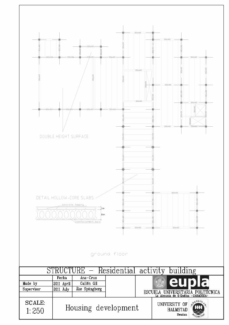
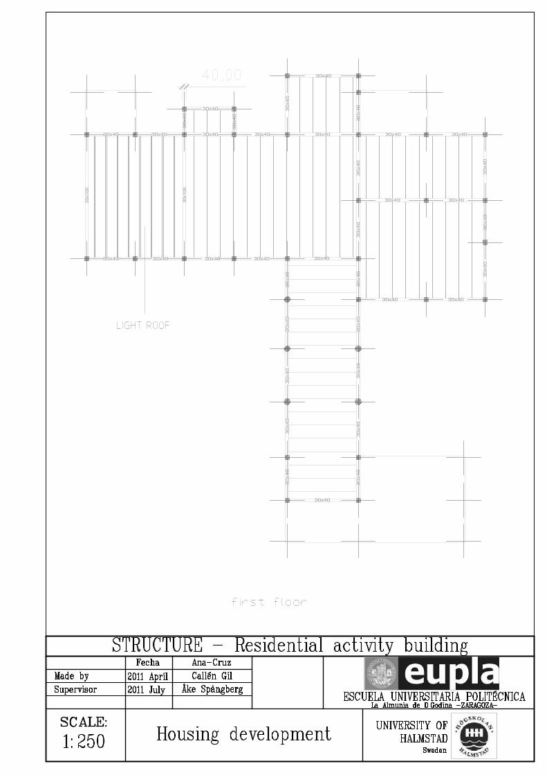


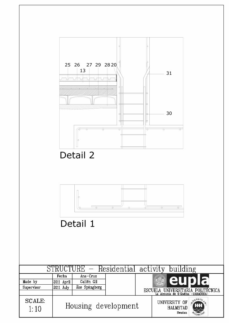

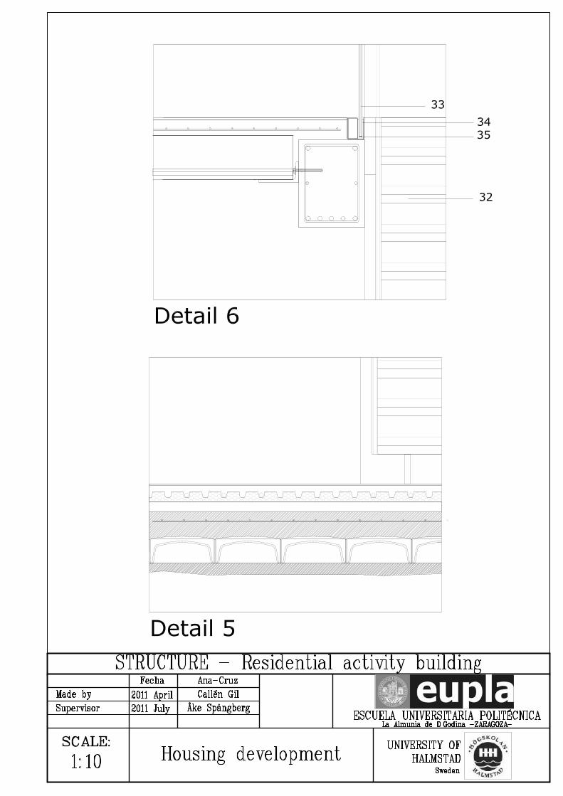


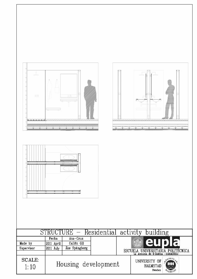
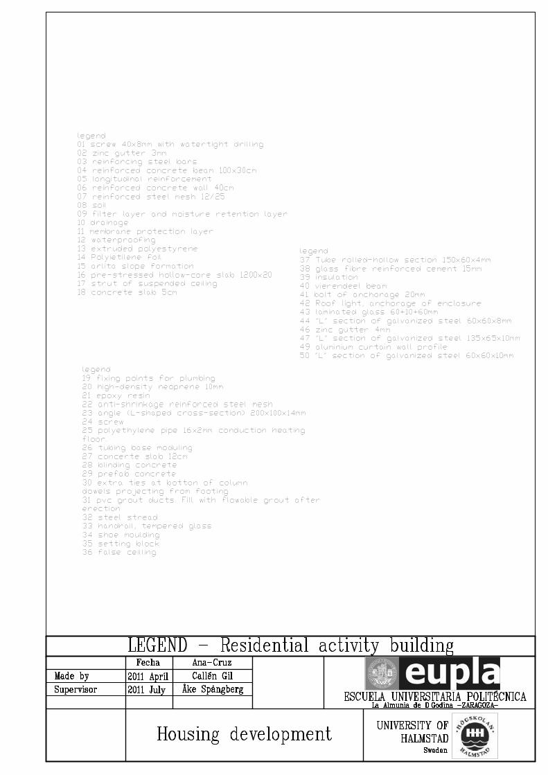


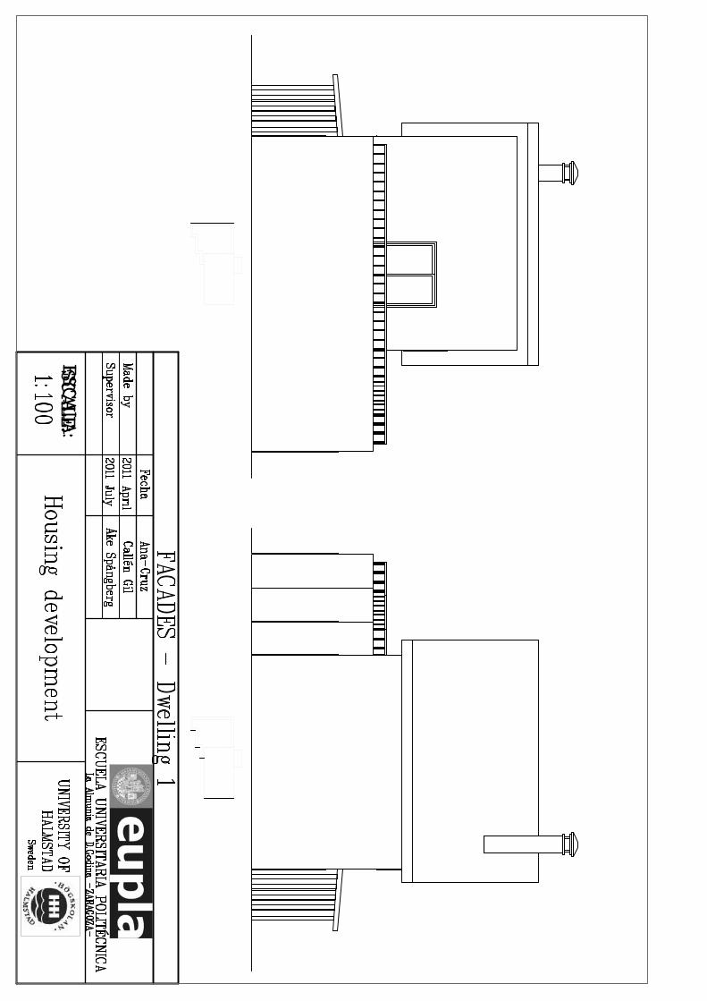


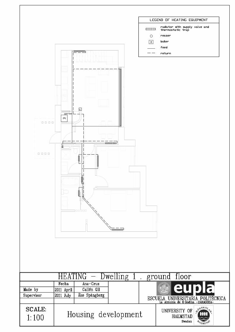
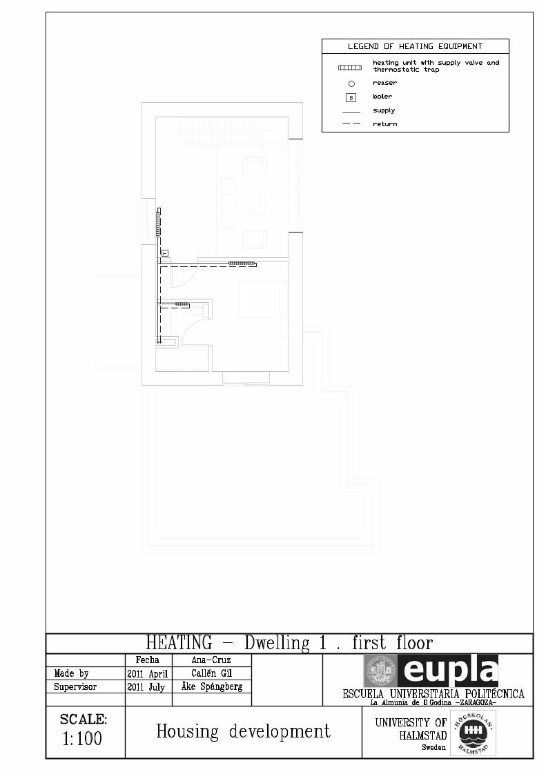
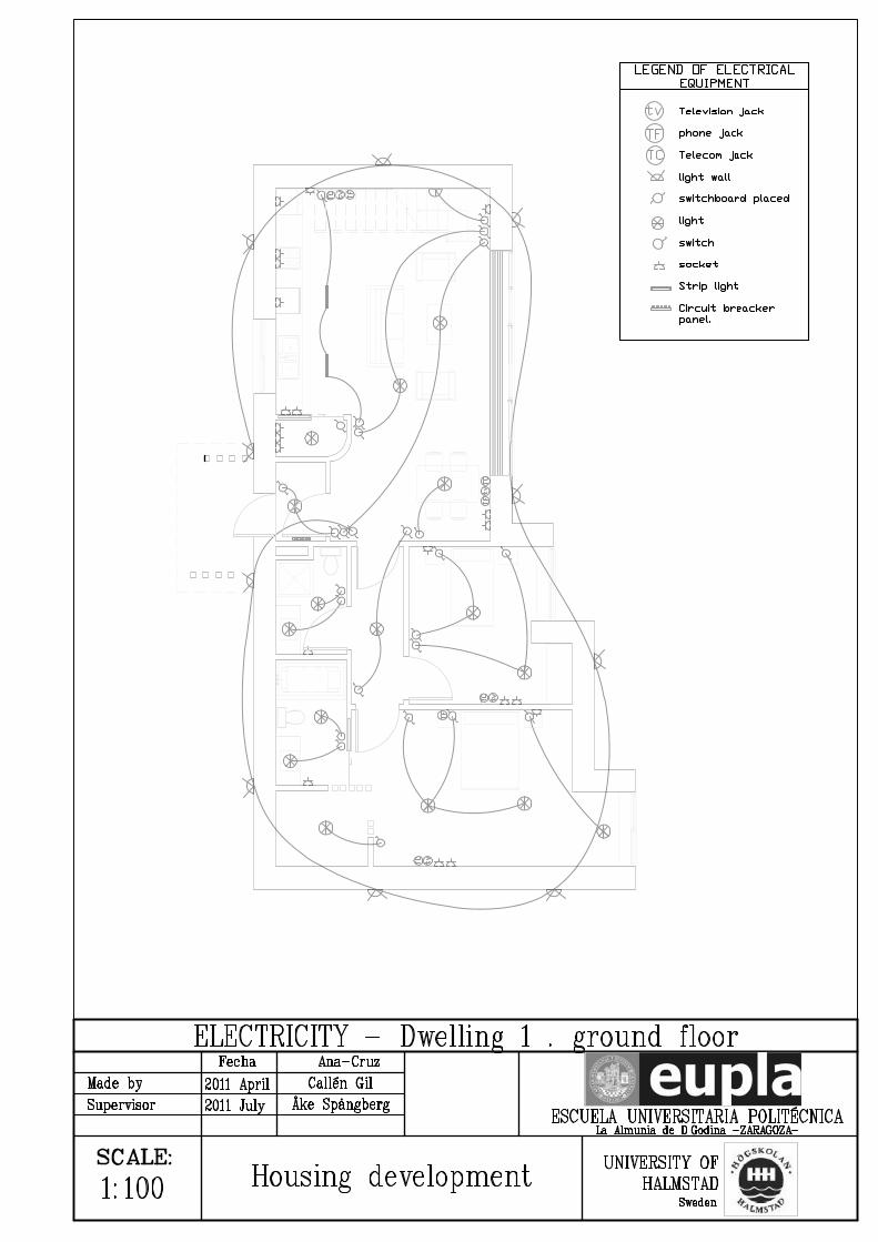
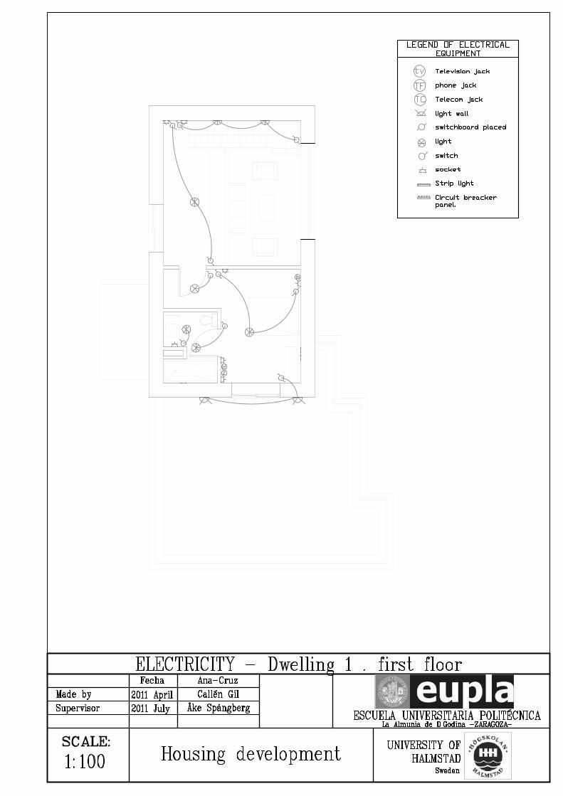
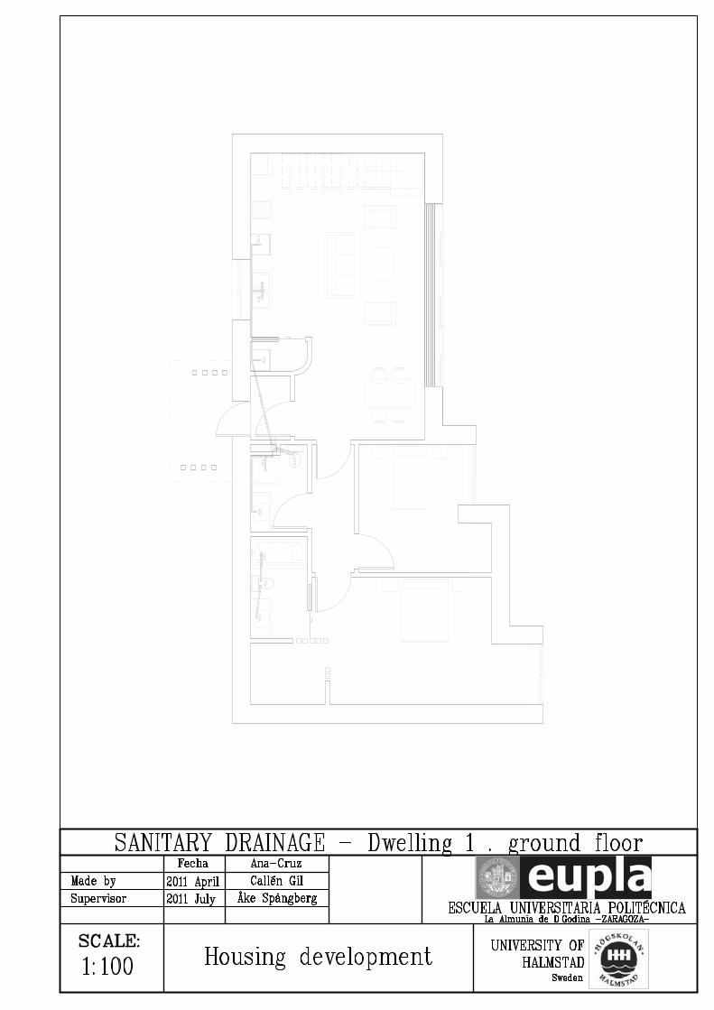


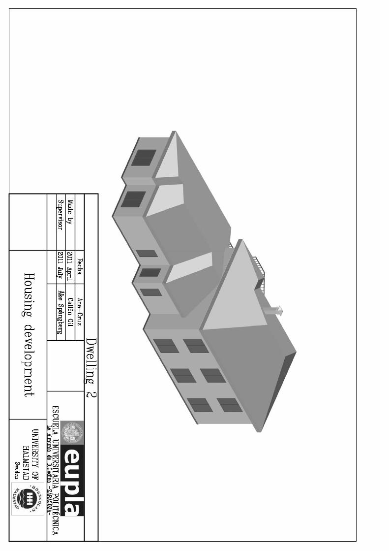

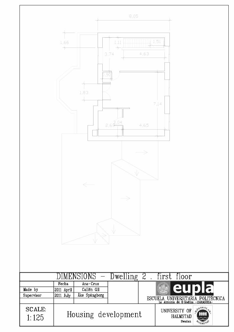

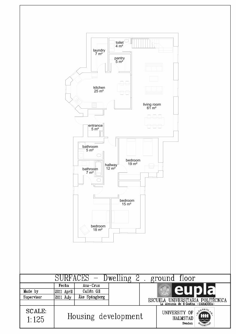

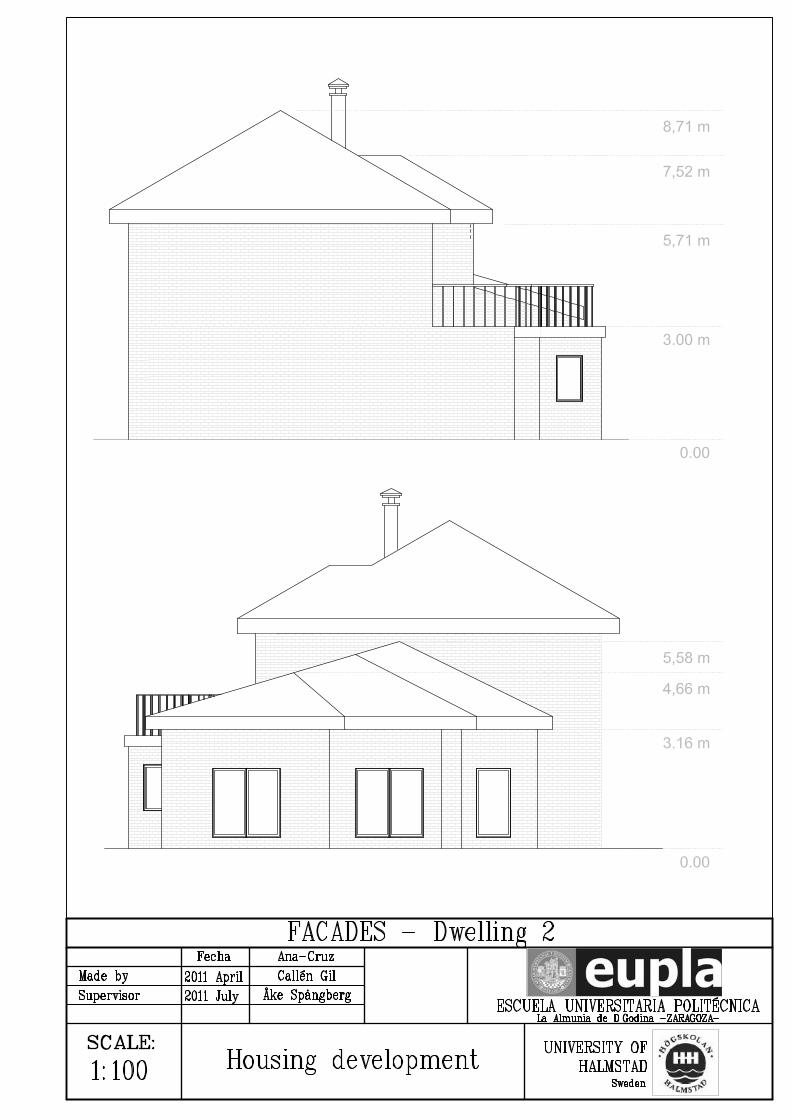
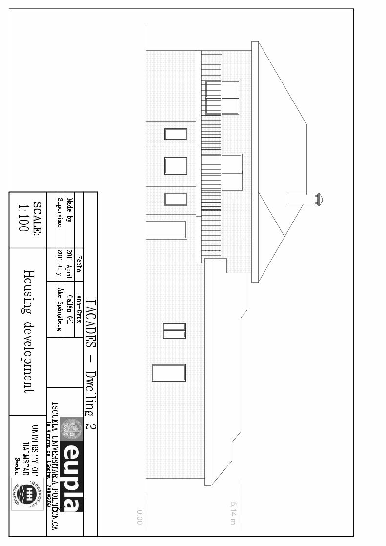


![PowerPoint Presentation · UNIVE I . hh.se HALMSTAD UNIVE I . hh.se HALMSTAD UNIVE I . hh.se HALMSTAD UNIVE I . Title: PowerPoint Presentation Author: Per-Ola Ulvenblad [peul] Created](https://static.documents.pub/doc/80x56/602fc2f942f8f67fe866b18d/powerpoint-presentation-unive-i-hhse-halmstad-unive-i-hhse-halmstad-unive.jpg)

