How Reliable is the Routing in Your SDH Network? Application Note 64 Advanced Network Test Solutions: Path trace analysis in complex SDH networks Wandel & Goltermann Communications Test Solutions
Transcript
How Reliable is the RoutinginYour SDH Network?
Application Note 64
Advanced NetworkTest Solutions:
Path trace analysis incomplex SDH networks
Wandel & GoltermannCommunications Test Solutions
Table of contents
The application of the Trace Identifierin complex SDH networks 3The arisal of a complextelecommunications environment 3
Trace Identifiers in thevarious SDH levels 4The J0 Byte in the RSOH 4The J1 byte in the VC-4 HP or as VC-3 LP 5The J2 byte in the VC-12 LP 5
Special meaning of the2 Mbit/s Trace Identifier 6
Differences between SDH systemsfrom different manufacturers 6
Use of the Trace Identifier in the ANT-20 7Selecting the channel for a givenTrace Identifier 7Activation / deactivation ofTrace Identifier monitoring 7Setting the Expected Trace Identifier value 8Setting the Trace Identifier on the transmit side 8Trace Identifier analysis 8Alarm detection and processing 9In-service monitoring of the Path Trace Identifierat a protected monitor point (PMP) 10The Path Trace Identifier in aSTM-1 VC-4 transparent leased line 11
Abbreviations
AIS Alarm Indication SignalAPS Automatic Protection SwitchingATM Asynchronous Transfer ModeC-n Container, n = 1 ... 4CRC Cyclic Redundancy CheckHP Higher Order PathJ0 Regenerator Section TraceJ1 Path Trace (POH in VC-3,4)J2 Path Trace (POH in VC-1,2)LP Lower Order PathMS Multiplex SectionMS-AIS Multiplex AISMSOH Multiplex Section OverheadNE Network ElementPOH Path OverheadRDI Remote Defect IndicatorRS Regenerator SectionRSOH Regenerator Section OverheadRX ReceiverSDH Synchronous Digital HierarchySOH Section OverheadSTM Synchronous Transport ModuleSTM-N Synchronous Transport Module,
Subject to change without noticeOrder no. E 3.99/WG1/64/3.5Printed in Germany
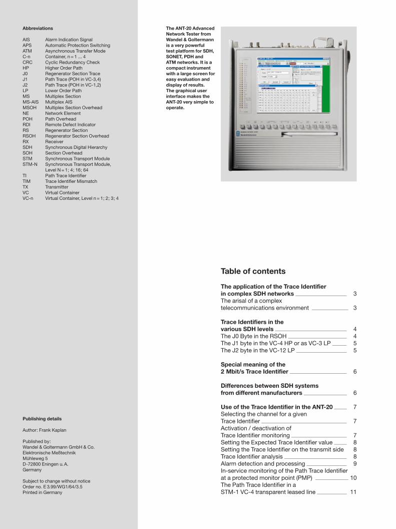
The ANT-20 AdvancedNetwork Tester fromWandel & Goltermannis a very powerfultest platform for SDH,SONET, PDH andATM networks. It is acompact instrumentwith a large screen foreasy evaluation anddisplay of results.The graphical userinterface makes theANT-20 very simple tooperate.
The application of the Trace Identifierin complex SDH networks
The arisal of a complextelecommunications environment
The removal of the state telecommunicationsmonopoly in many countries has lead to a rapidincrease in the number of domestic networkoperators and service providers.
Not all of these competing network providers canachieve complete coverage with their own back-bone networks. Particularly for long-distancetraffic, they tend to lease transport capacity fromcompetitors. This applies especially to the manymobile radio network operators, who dependon the 2 Mbit/s transport channels from a full-coverage backbone network. Added on top of thisare the many new Internet providers, PBX inter-connections, router links between local area net-works (LANs) and, due to the construction of newATM networks, providers of broadband multimediaservices, all of whom need a share of the transportcapacity of WANs. In the end run, all of thesefactors are creating more and more complexnetwork environments with many network inter-connections.
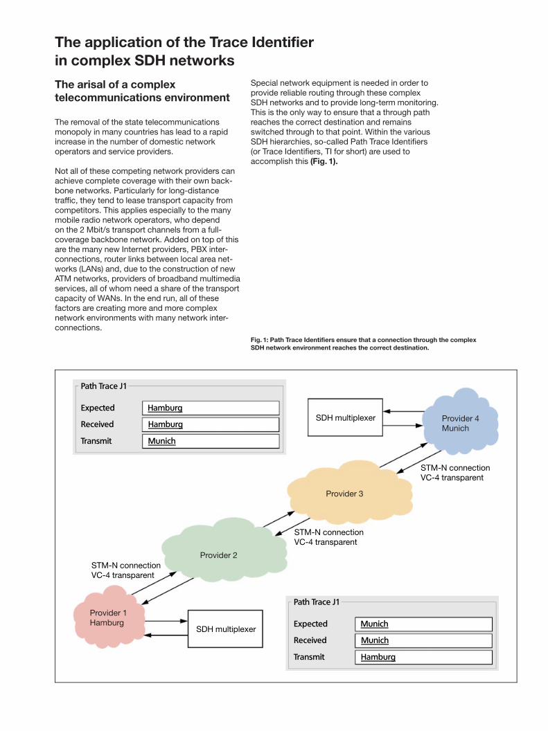
Special network equipment is needed in order toprovide reliable routing through these complexSDH networks and to provide long-term monitoring.This is the only way to ensure that a through pathreaches the correct destination and remainsswitched through to that point. Within the variousSDH hierarchies, so-called Path Trace Identifiers(or Trace Identifiers, TI for short) are used toaccomplish this (Fig. 1).
Path Trace J1
Expected Munich
Received Munich
Transmit Hamburg
Path Trace J1
Expected Hamburg
Received Hamburg
Transmit Munich
SDH multiplexer
STM-N connectionVC-4 transparent
Provider 2
STM-N connectionVC-4 transparent
Provider 3
Provider 4Munich
STM-N connectionVC-4 transparent
SDH multiplexer
Provider 1Hamburg
Fig. 1: Path Trace Identifiers ensure that a connection through the complexSDH network environment reaches the correct destination.
Trace Identifiers in thevarious SDH levels
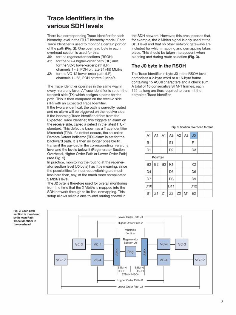
There is a corresponding Trace Identifier for eachhierarchy level in the ITU-T hierarchy model. EachTrace Identifier is used to monitor a certain portionof the path (Fig. 2). One overhead byte in eachoverhead section is used for this:J0: for the regenerator sections (RSOH)J1: for the VC-4 higher-order path (HP) and
for the VC-3 lower-order path (LP),channels 1 - 3, PDH bit rate 34 (45) Mbit/s
J2: for the VC-12 lower-order path (LP),channels 1 - 63, PDH bit rate 2 Mbit/s
The Trace Identifier operates in the same way inevery hierarchy level: A Trace Identifier is set on thetransmit side (TX) which assigns a name for thepath. This is then compared on the receive side(TR) with an Expected Trace Identifier.If the two are identical, the path is correctly routedand no alarm will be triggered on the receive side.If the incoming Trace Identifier differs from theExpected Trace Identifier, this triggers an alarm onthe receive side, called a defect in the latest ITU-Tstandard. This defect is known as a Trace IdentifierMismatch (TIM). If a defect occurs, the so-calledRemote Defect Indicator (RDI) alarm is set for thebackward path. It is then no longer possible totransmit the payload in the corresponding hierarchylevel and the levels below it (Regenerator SectionOverhead, Higher Order Path or Lower Order Path)(see Fig. 2).In practice, monitoring the routing at the regener-ator section level (J0 byte) has little meaning, sincethe possibilities for incorrect switching are muchless here than, say, at the much more complicated2 Mbit/s level.The J2 byte is therefore used for overall monitoringfrom the time that the 2 Mbit/s is mapped into theSDH network through to its final demapping. Thissetup allows reliable end-to-end routing control in
the SDH network. However, this presupposes that,for example, the 2 Mbit/s signal is only used at theSDH level and that no other network gateways areincluded for which mapping and demapping takesplace. This should be taken into account whenplanning and during route selection (Fig. 3).
The J0 byte in the RSOH
The Trace Identifier in byte J0 in the RSOH levelcomprises a 2-byte word or a 16-byte framecontaining 15 ASCII characters and a check sum.A total of 16 consecutive STM-1 frames, each125 ms long are thus required to transmit thecomplete Trace Identifier.
3
Higher Order Path J1
Lower Order Path J2
Lower Order Path J1
Higher Order Path J1
MultiplexSection
RegeneratorSection J0
Fig. 2: Each pathsection is monitoredby its own PathTrace Identifier inthe overhead.
Fig. 3: Section Overhead format
A1 A1 A1 A2 A2 A2 J0
B1 E1 F1
D1 D2 D3
Pointer
B2 B2 B2 K1 K2
D4 D5 D6
D7 D8 D9
D10 D11 D12
S1 Z1 Z1 Z2 Z2 M1 E2
STM-NRSOH
STM-NRSOH
STM-N MSOH
The J1 byte in the VC-4 HP or asVC-3 LP
The Trace Identifiers for the HP level in VC-4 or forthe LP level in VC-3 (34 Mbit/s or 45 Mbit/s pay-load) are identical. They comprise 16 J1 bytes thatare combined into a frame of 15 ASCII charactersand a check sum as per ITU-T G.707. In thismethod, the Trace Identifier is only evaluated onthe receive side if the incoming CRC check sumand the check sum calculated by the receiver are inagreement. Again, 16 consecutive STM-1 framesare needed to transmit this Trace Identifier. Foreasy detection of the CRC check sum, the first bitof the first byte is set to `̀ 1º while the first bit in theremaining 15 bytes is set to `̀ 0º (Fig. 4 and 5).
In practice, it may be that a bit error occurs in anASCII character of the Trace Identifier during trans-mission. The incorrect Trace Identifier results inthe triggering of a Trace Identifier Mismatch Alarmon the receive side, even though the routing wascorrect. Since the CRC check sum of the incomingsignal and the check sum calculated for thereceiver do not agree, the Trace Identifier will berejected and not evaluated.
A further method of transmitting the Trace Identifieruses a 64 byte frame. The frame end is indicatedby the ASCII value 00D (CR) for ASCII character 64or 00A (LF) for ASCII character 63. 64 consecutiveSTM-1 frames are needed to transmit this TraceIdentifier. In practice, however, a 16-byte TraceIdentifier is used.
If a STM-1 signal consists of a VC-4 with3634 Mbit/s substructure, then in addition to theVC-4 level Trace Identifier (Higher Order Path TraceIdentifier) separate Trace Identifiers also exist foreach of the 34 Mbit/s channels (Lower Order PathTrace Identifiers) on the VC-3 level.
The J2 byte in the VC-12 LP
On the LP level in the VC-12 (2 Mbit/s), the TraceIdentifier is formed from the J2 byte (Fig. 6).Basically the same method is used as for the J1byte in the VC-4/VC-3. Since the VC-12 only hasone overhead byte, the four bytes shown in Fig. 6must be transmitted periodically one after theother. The H4 byte in the VC-4 overhead is usedto indicate which byte is being transmitted atthe moment (Fig. 4); this counts up from 0 to 3continually, thus serving as a pointer for the VC-12overhead byte. 4 byte sequences and hence 64STM-1 frames are required to transmit a complete16 byte Trace Identifier, so a 64 byte Trace Identifierwould require 4664 = 256 STM-1 frames.
For a STM-1 frame structure with VC-4 loadedwith 63 2 Mbit/s channels there is a total of further63 Trace Identifiers on the VC-12 level in additionto the Trace Identifier on the VC-4 level.
4
J1
B3
C2
G1
F2
H4
F3
K3
N1
Trace Identifier
Quality Monitoring
Container Contents
Error Reporting
Maintenance
Multiframe Indicator
Maintenance
Automatic Protection Switching
Tandem Connection Monitoring
Format according to ITU-T G.707
1 C C C C C C C
0 X X X X X X X
0 X X X X X X X
.
.
.
0 X X X X X X X
0 X X X X X X X
0 X X X X X X X
0 X X X X X X X
Start of the16-byte frame
15-byte ASCII character
Fig. 5: The Trace Identifier consists of 16 J1 bytes (15 ASCII characters and check sum)combined into a frame (format as per ITU-T G.707).
V5
J2
N2
K4
Path Overhead VC-12
Trace Identifier
Tandem Connection Monitoring
Automatic Protection Switching
Fig. 4: The TraceIdentifier istransmitted inthe J1 byte ofthe overhead.
Fig. 6: The J2 byteforms the TraceIdentifier on theVC-12 LP level.
Special meaning of the 2 Mbit/s Trace Identifier
The 2 Mbit/s Trace Identifier has a special meaningin the SDH network environment. The reason forthis is the large number of existing connections andtheir complex interconnection. A link from A to Bcan be via the networks of different providers.Fig. 1 shows a connection from Hamburg to Munichvia four different network providers, of whom twoare city network providers and two are multi-regional providers. The last mile of the connectionis provided by the city networks. Each of these net-work providers has their own network managementsystem which is limited to their own property area.Trace Identifiers ensure that incorrect routing is
detected immediately, despite the distributedmanagement, and that appropriate remedial actioncan be taken straight away. If there were no TraceIdentifiers, only the end user would notice that theconnection was no longer functioning if incorrectswitching in one of the network sections causeda 2 Mbit/s connection to be routed to anotherlocation with the same signal structure.For the application of the Trace Identifier to beuseful, a system of assigning identifications thatspecify the source of the signal as exactly aspossible needs to be set up first.
5
Differences between SDH systemsfrom different manufacturers
There are differences in the way that the TraceIdentifier function is implemented by differentsystem manufacturers. While some systems manu-facturers have yet to integrate this function intotheir latest systems, others have incorporated thefunction but not on every hierarchy level. Still othermanufacturers have realized the function on alllevels completely, but it cannot be disabled. A fullsolution would mean that Trace Identifiers shouldbe implemented on every SDH hierarchy level insuch a way as they can be disabled if required.
A further problem is given by the fact that differentmanufacturer's systems use different methodsfor automatically filling the Trace Identifier to15 ASCII characters when less than 15 charactersare entered due to an incomplete identifierassignment. For example, some manufacturers'systems fill the blanks with spaces (ASCII value200) as shown in Fig. 7. The other possibility is touse the ASCII zero character (ASCII value 000) asshown in Fig. 8.
Since the ASCII values from Fig. 7 and Fig. 8 arenot the same, a Trace Identifier Mismatch (TIM)alarm will result if the wrong setting is made on thereceive side, even though both the Trace Identifiersare set to identical values. This problem often leadsto difficulties in coupling SDH networks togetherwhen they are made up from system componentsfrom different manufacturers. The same can alsooccur within a SDH network if network elementsfrom various sources are combined together.
It is therefore important to have a SDH analyzeravailable when coupling networks. This should becapable of displaying the individual characters inASCII format so that the differences in the TraceIdentifier fillers can be seen. This is important, too,because the network management system can notusually indicate any difference between spacesand ASCII zeros.
Selection of the channel in which measurementsare to be made or in which the Trace Identifier is tobe analyzed is made using the `̀ Signal StructureEditorº of the ANT-20. The same procedure is alsoused for the Trace Identifier itself.
In the following example, the 2 Mbit/s channelwith the number 1 is selected in the ANT-20 signalstructure editor (Fig. 9).
Activation / deactivation of TraceIdentifier monitoring
A check (✓) in the settings of the `̀ OverheadAnalyzerº activates the Trace Identifier in thecorresponding hierarchy level (Fig. 10). If theTrace Identifier on the receive side is activated,the incoming Trace Identifier can be displayed.Otherwise, viewing the incoming Trace Identifieris not possible. The default settings are restoredby pressing the ªDefaultº button.
6
Fig. 9: ANT-20 signal structure editor
Fig. 10: The setting menus for theANT-20 `̀ Overhead Analyzerº
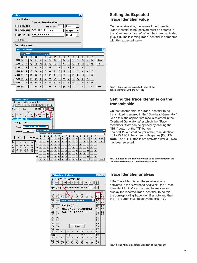
Setting the ExpectedTrace Identifier value
On the receive side, the value of the ExpectedTrace Identifier to be received must be entered inthe `̀ Overhead Analyzerº after it has been activated(Fig. 11). The incoming Trace Identifier is comparedwith this expected value.
Setting the Trace Identifier on thetransmit side
On the transmit side, the Trace Identifier to betransmitted is entered in the `̀ Overhead Generatorº.To do this, the appropriate byte is selected in theOverhead Generator, after which the `̀ TraceIdentifier Editorº can be opened by clicking the`̀ Editº button or the `̀ TIº button.The ANT-20 automatically fills the Trace Identifierup to 15 ASCII characters with spaces (Fig. 12).Note: The `̀ TIº button is not activated until a J bytehas been selected.
Trace Identifier analysis
If the Trace Identifier on the receive side isactivated in the `̀ Overhead Analyzerº, the `̀ TraceIdentifier Monitorº can be used to analyze anddisplay the received Trace Identifier. To do this,the corresponding Trace Identifier byte and thenthe ªTIº button must be activated (Fig. 13).
7
Fig. 11: Entering the expected value of theTrace Identifier with the ANT-20
Fig. 13: The ªTrace Identifier Monitorº of the ANT-20
Fig. 12: Entering the Trace Identifier to be transmitted in the`̀ Overhead Generatorº on the transmit side
Alarm detection andprocessing
The way that the payload signal is affected variesdepending on the SDH hierarchy level in which aTrace Identifier is evaluated. This can range from ablockade of a single 2 Mbit/s payload signal in theLP level up to a blockade of the entire payloadsignal in the regenerator section. The next part ofthis Application Note describes the effects on theindividual levels (Fig. 14).
If the J0 byte in the regenerator section signals aTrace Identifier Mismatch Alarm (RS-TIM), thisresults in the Alarm Indication Signal (AIS) beingset to `̀ all onesº and transmitted to the multiplexsection. At this point, the Multiplex Section RemoteDefect Indicator (MS-RDI) is activated for thereturn path. The AIS has an effect right down to thepayload channel level via the higher-order path andthe lower-order path. Transmission of payloadsignals is therefore no longer possible. Since thisalso applies to STM-4 or STM-16 signals, the resultmay finally be that the entire payload cannot betransmitted.
If the J1 byte in the higher-order path level signalsa TIM alarm (HP-TIM), the Alarm Indication Signal(AIS) is set to `̀ all onesº and passed on to thelower-order path level. Here, the higher-order pathRemote Defect Indicator (HP-RDI) is activated forthe return path. The AIS has an effect right downto the payload channels via the lower-order path.Transmission of payload signals then becomesimpossible in all payload channels of the affectedVC-4.
If the J2 byte in the lower-order path level signalsa TIM alarm (RS-TIM), the Alarm Indication Signal(AIS) is set to `̀ all onesº and passed on to theaffected payload (VC-12). There, the lower-orderpath Remote Defect Indicator (LP-RDI) is activatedfor the return path. This means that transmissionof payload signals is impossible in this channel.
8
Fig. 14:SDH maintenanceinteractions
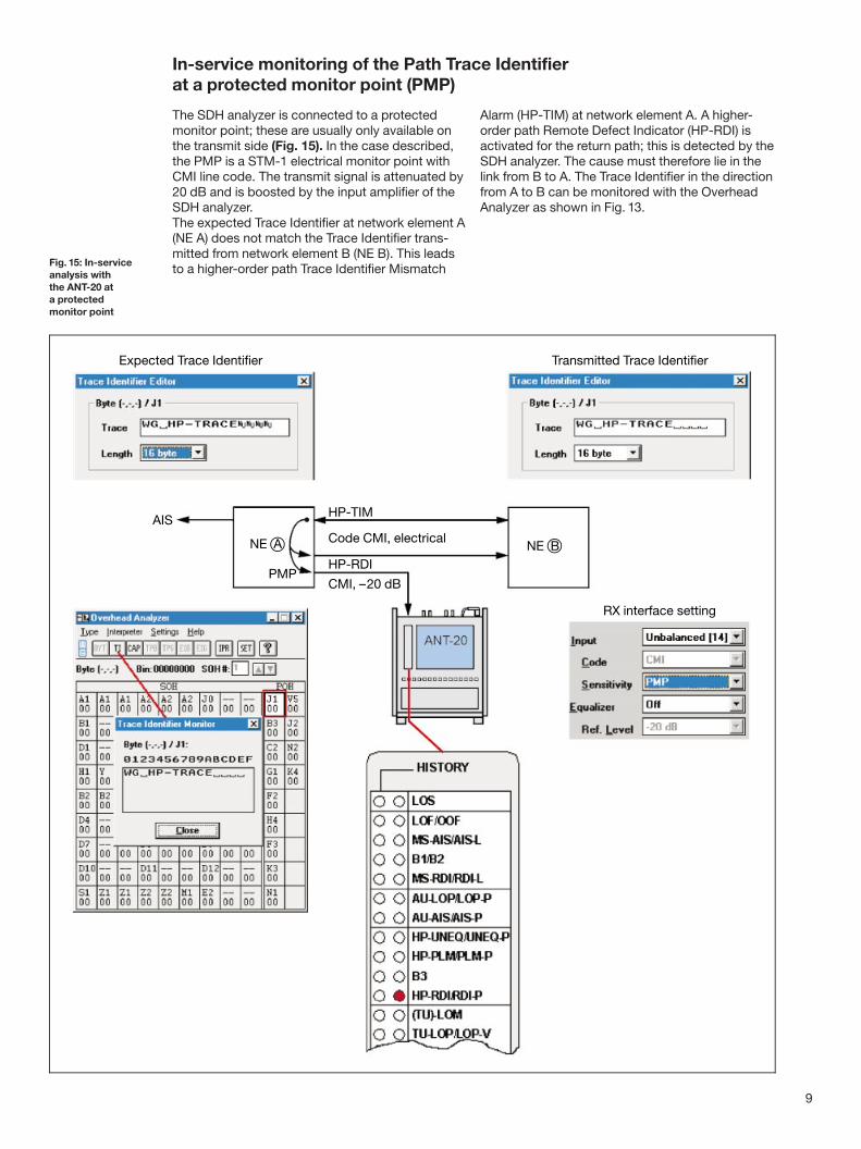
In-service monitoring of the Path Trace Identifierat a protected monitor point (PMP)
The SDH analyzer is connected to a protectedmonitor point; these are usually only available onthe transmit side (Fig. 15). In the case described,the PMP is a STM-1 electrical monitor point withCMI line code. The transmit signal is attenuated by20 dB and is boosted by the input amplifier of theSDH analyzer.The expected Trace Identifier at network element A(NE A) does not match the Trace Identifier trans-mitted from network element B (NE B). This leadsto a higher-order path Trace Identifier Mismatch
Alarm (HP-TIM) at network element A. A higher-order path Remote Defect Indicator (HP-RDI) isactivated for the return path; this is detected by theSDH analyzer. The cause must therefore lie in thelink from B to A. The Trace Identifier in the directionfrom A to B can be monitored with the OverheadAnalyzer as shown in Fig. 13.
Fig. 15: In-serviceanalysis withthe ANT-20 ata protectedmonitor point
The Path Trace Identifierin a STM-1 VC-4 transparent leased line
STM-1 VC-4 transparent leased lines (as perETSI EN 301164, chapter 5) are mainly used bynetwork providers that do not have their ownoptical fiber paths, forming their entire SDH net-work from these leased lines. Cross connects areinstalled at the crossing points of the STM-1 paths.These allow flexible switching of the payload(VC-4 containers). This type of circuit is also usedby network providers in regions where they do notmaintain their own infrastructure.
This type of STM-1 leased line allows the payloadto be filled with any payload (VC-4 transparent).As Fig. 16 shows, the entire higher order pathoverhead is contained in the payload. The J1 byte,which is responsible for the higher-order pathTrace Identifier is included in this. This TraceIdentifier is thus transmitted over a STM-1 VC-4transparent leased line from one end to the otherend without any changes; this can be verified usinga SDH analyzer (see Fig. 17 for test setup).
10
ANT-20
Provider 2
STM-N connectionVC-4 transparent
Provider 3
Provider 4Munich
STM-N connectionVC-4 transparent
ANT-20
Provider 1Hamburg
STM-N connectionVC-4 transparent
Payload VC-4(transport capacity bulk signal)
Fig. 16: The entirehigher-order pathoverhead with theJ1 byte is withinthe payload.
Fig. 17: Test setup with ANT-20 for end-to-end measurementon a transparent leased line
Brazil/Chile/Peru/Bolivia/ParaguayWandel & GoltermannInstrumentacË aÄ o Ltda. & Cia.Av. Eng. Luis Carlos Berrini,936-9. andar04571-000 SaÄ o Paulo, SPBrazilTel. +55-11 5503 3800Fax +55-11 5505 1598