15
How to Read Electrical Diagrams
How to Read Electrical Diagrams
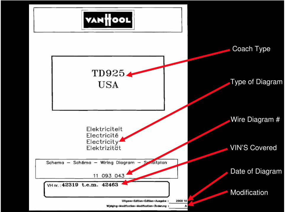
Coach Type
Type of Diagram
Wire Diagram #
VIN’S Covered
Date of Diagram
Modification
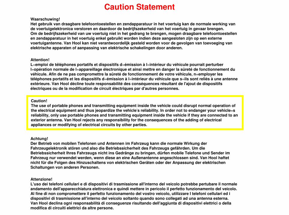
Caution Statement
Caution!The use of portable phones and transmitting equipment inside the vehicle could disrupt normal operation of the electrical equipment and thus jeopardize the vehicle’s reliability. In order not to endanger your vehicle=s reliability, only use portable phones and transmitting equipment inside the vehicle if they are connected to an exterior antenna. Van Hool rejects any responsibility for the consequences of the adding of electrical appliances or modifying of electrical circuits by other parties.
Waarschuwing!Het gebruik van draagbare telefoontoestellen en zendapparatuur in het voertuig kan de normale werking van de voertuigelektronica verstoren en daardoor de bedrijfszekerheid van het voertuig in gevaar brengen.Om de bedrijfszekerheid van uw voertuig niet in het gedrang te brengen, mogen draagbare telefoontoestellenen zendapparatuur in het voertuig enkel gebruikt worden indien deze aangesloten zijn op een externevoertuigantenne. Van Hool kan niet verantwoordelijk gesteld worden voor de gevolgen van toevoeging van elektrische apparaten of aanpassing van elektrische schakelingen door anderen.
Attention!L=emploi de téléphones portatifs et dispositifs d=émission à l=intérieur du véhicule pourrait perturberl=opération normale de l=appareillage électronique et ainsi mettre en danger la sûreté de fonctionnement du véhicule. Afin de ne pas compromettre la sûreté de fonctionnement de votre véhicule, n=employer lestéléphones portatifs et les dispositifs d=émission à l=intérieur du véhicule que s=ils sont reliés à une antenneextérieure. Van Hool décline toute responsabilité des conséquences résultant de l'ajout de dispositifsélectriques ou de la modification de circuit électriques par d'autres personnes.
Achtung!Der Betrieb von mobilen Telefonen und Antennen im Fahrzeug kann die normale Wirkung derFahrzeugelektronik stören und also die Betriebssicherheit des Fahrzeugs gefährden. Um die Betriebssicherheit Ihres Fahrzeugs nicht ins Gedränge zu bringen, dürfen mobile Telefone und Sender imFahrzeug nur verwendet werden, wenn diese an eine Außenantenne angeschlossen sind. Van Hool haftetnicht für die Folgen des Hinzuschaltens von elektrischen Geräten oder der Anpassung der elektrischenSchaltungen von anderen Personen.
Attenzione!L'uso dei telefoni cellulari e di dispositivi di trasmissione all'interno del veicolo potrebbe pertubare il normaleandamento dell'apparecchiatura elettronica e quindi mettere in pericolo il perfetto funzionamento del veicolo.Al fine di non compromettere il perfetto funzionamento del vostro veicolo, utilizzare I telefoni cellulari ed i dispositivi di trasmissione all'interno del veicolo soltanto quando sono collegati ad una antenna esterna.Van Hool declina ogni responsabilità di conseguenze risultando dell'aggiunta di dispositivi elettrici o dellamodifica di circuiti elettrici da altre persone.
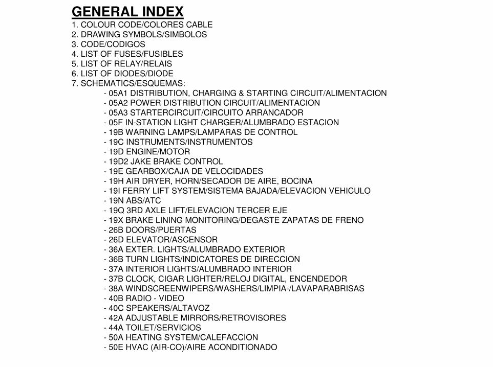
GENERAL INDEX1. COLOUR CODE/COLORES CABLE
2. DRAWING SYMBOLS/SIMBOLOS
3. CODE/CODIGOS4. LIST OF FUSES/FUSIBLES
5. LIST OF RELAY/RELAIS
6. LIST OF DIODES/DIODE
7. SCHEMATICS/ESQUEMAS:
- 05A1 DISTRIBUTION, CHARGING & STARTING CIRCUIT/ALIMENTACION- 05A2 POWER DISTRIBUTION CIRCUIT/ALIMENTACION
- 05A3 STARTERCIRCUIT/CIRCUITO ARRANCADOR
- 05F IN-STATION LIGHT CHARGER/ALUMBRADO ESTACION
- 19B WARNING LAMPS/LAMPARAS DE CONTROL
- 19C INSTRUMENTS/INSTRUMENTOS- 19D ENGINE/MOTOR
- 19D2 JAKE BRAKE CONTROL
- 19E GEARBOX/CAJA DE VELOCIDADES
- 19H AIR DRYER, HORN/SECADOR DE AIRE, BOCINA- 19I FERRY LIFT SYSTEM/SISTEMA BAJADA/ELEVACION VEHICULO
- 19N ABS/ATC
- 19Q 3RD AXLE LIFT/ELEVACION TERCER EJE
- 19X BRAKE LINING MONITORING/DEGASTE ZAPATAS DE FRENO
- 26B DOORS/PUERTAS- 26D ELEVATOR/ASCENSOR
- 36A EXTER. LIGHTS/ALUMBRADO EXTERIOR
- 36B TURN LIGHTS/INDICATORES DE DIRECCION
- 37A INTERIOR LIGHTS/ALUMBRADO INTERIOR
- 37B CLOCK, CIGAR LIGHTER/RELOJ DIGITAL, ENCENDEDOR- 38A WINDSCREENWIPERS/WASHERS/LIMPIA-/LAVAPARABRISAS
- 40B RADIO - VIDEO
- 40C SPEAKERS/ALTAVOZ
- 42A ADJUSTABLE MIRRORS/RETROVISORES
- 44A TOILET/SERVICIOS- 50A HEATING SYSTEM/CALEFACCION
- 50E HVAC (AIR-CO)/AIRE ACONDITIONADO


V-RGS
1. THE COLOR CODE IS AN ABBREVIATION
FROM THE DUTCH WORDING.
2. These are two types of color coding used
throughout the electrical drawings:
A. Solid color: ge
B. Solid color with single tracer: ge-b
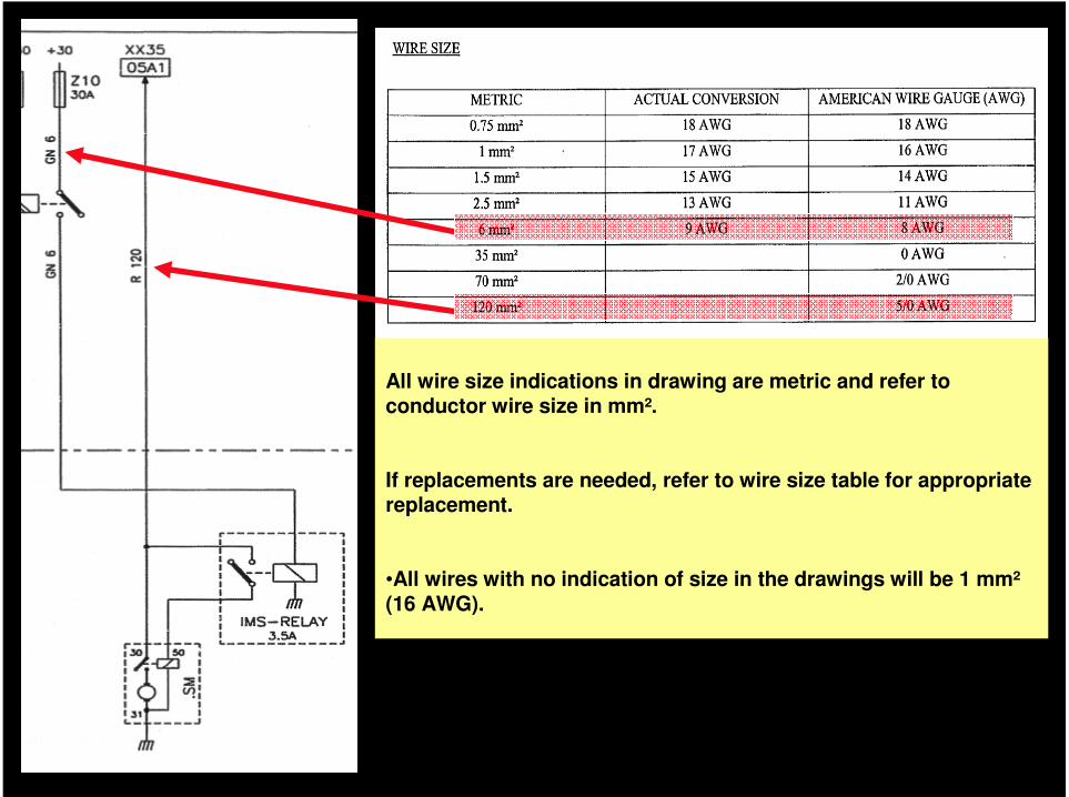
All wire size indications in drawing are metric and refer to conductor wire size in mm².
If replacements are needed, refer to wire size table for appropriate replacement.
•All wires with no indication of size in the drawings will be 1 mm²(16 AWG).

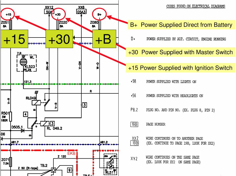
+15 +30 +B
B+ Power Supplied Direct from Battery
+30 Power Supplied with Master Switch
+15 Power Supplied with Ignition Switch

XX12 .36B:
Wire continues on to another page.
(EX. Continues to page 36B, Look
For XX12)
P101.3 Plug NO. and PIN NO.
(EX. Plug 101, Pin 3)
TB10 is indicated on the index page as
a Terminal Stud 24v.
TB10
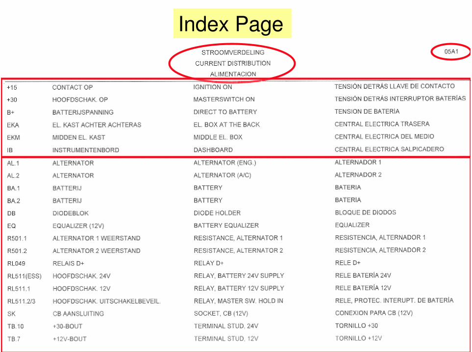
Index Page
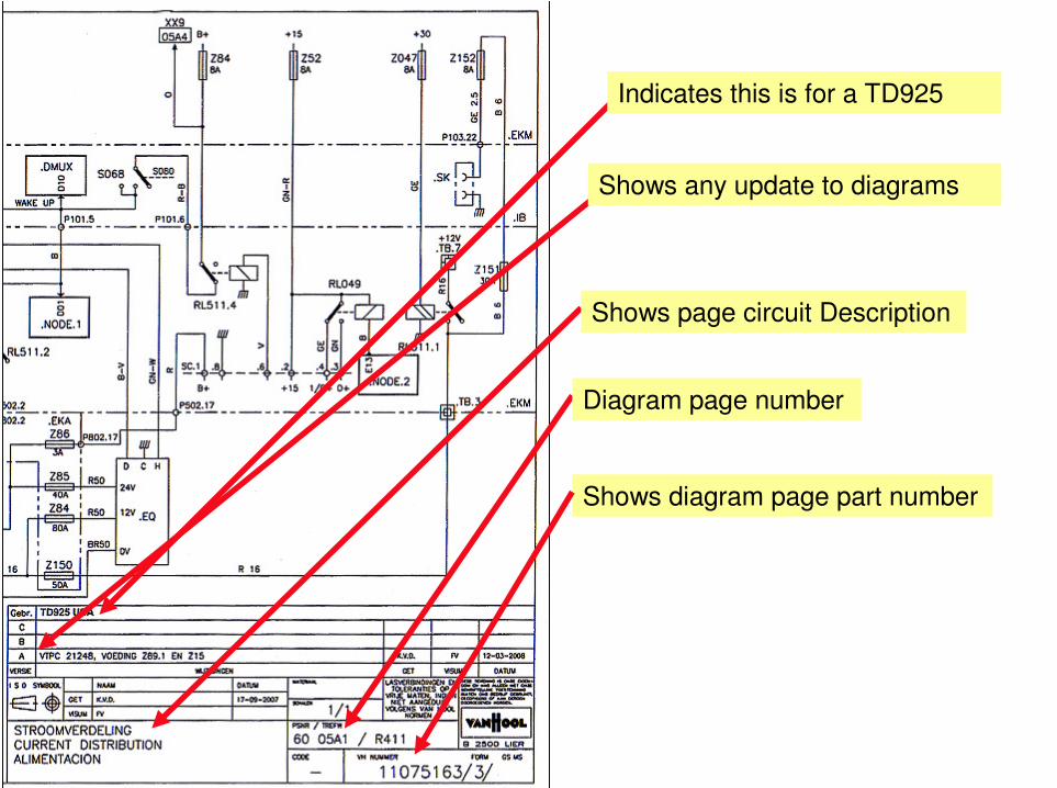
Indicates this is for a TD925
Shows any update to diagrams
Shows page circuit Description
Diagram page number
Shows diagram page part number
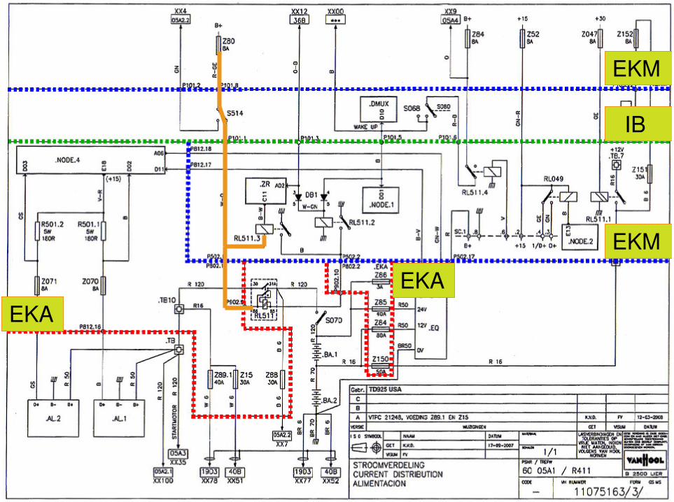
EKM
IB
EKM
EKA
EKA
Troubleshooting Tips
1. Know your circuit you are working on.
2. Check for clean & tight connections.
4. Pick a starting point to start checking your circuit.
3. Check all plugs are in securely and corrosive free.