37
Exisng Condions Experience: View NE along Howe Street near #101 Howe Street Solar Array Visual Migaon Analysis | Ashland, MA
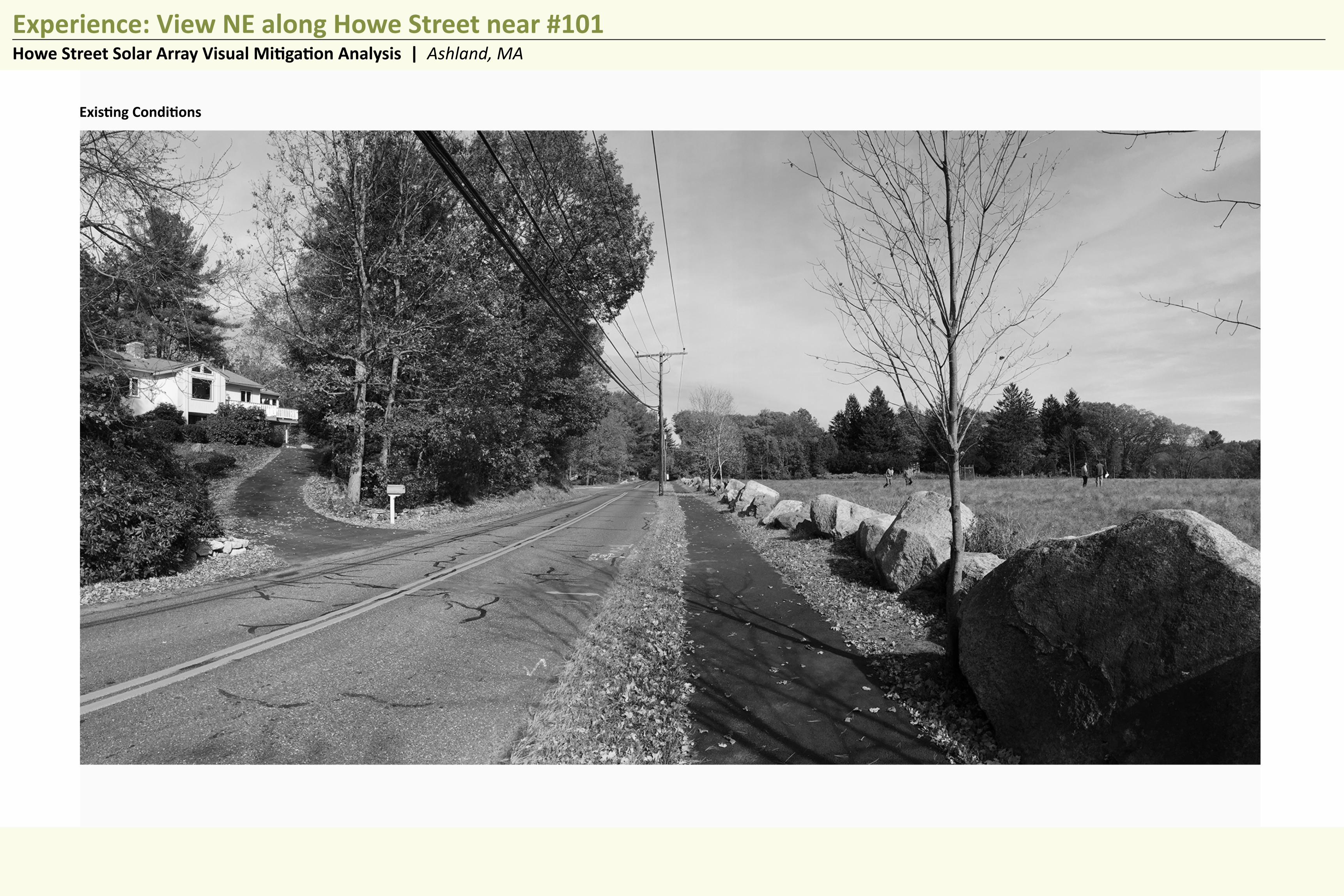
Existing Conditions
BEALS+THOMAS AMERESCO SolarPortland, ME
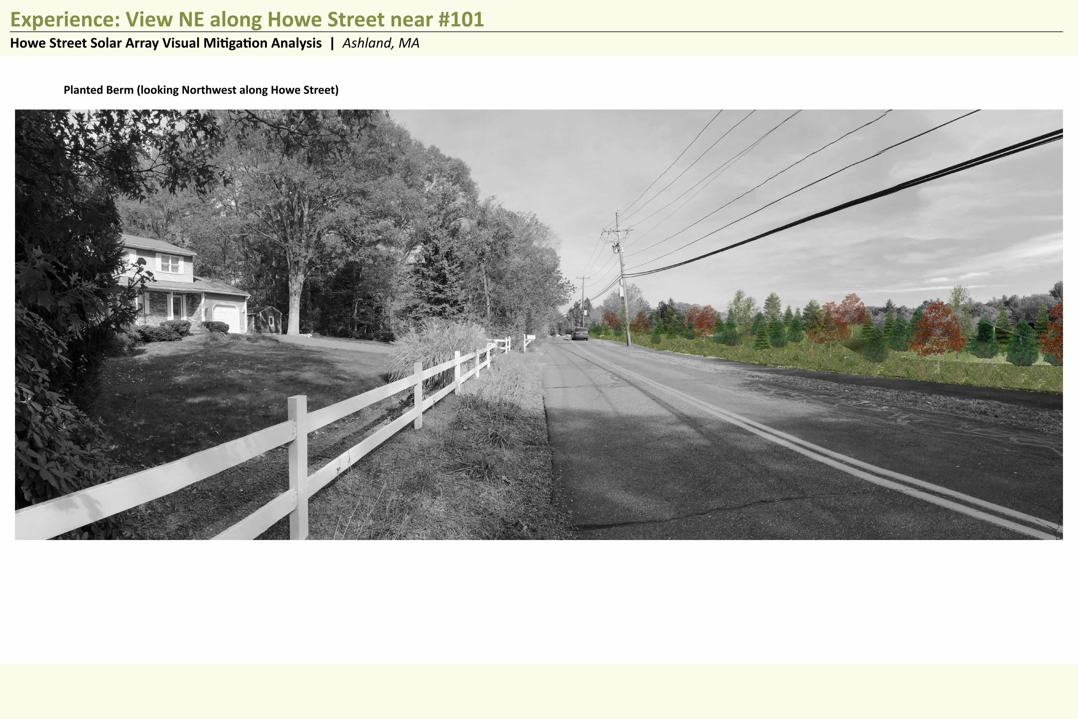
Experience: View NE along Howe Street near #101
DATE: 11/23/2015B+T FILE NO: 266900P002
Howe Street Solar Array Visual Mitigation Analysis | Ashland, MA

Solar Array without Mitigation
BEALS+THOMAS AMERESCO SolarPortland, MEDATE: 11/23/2015
B+T FILE NO: 266900P002
Experience: View NE along Howe Street near #101Howe Street Solar Array Visual Mitigation Analysis | Ashland, MA
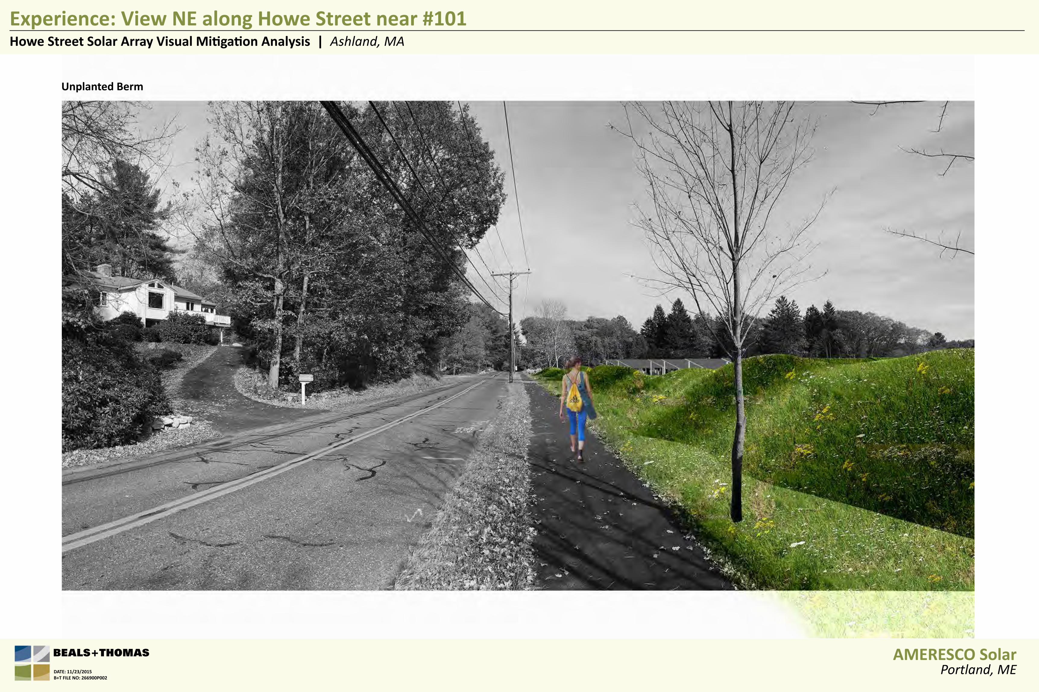
Unplanted Berm
BEALS+THOMAS AMERESCO SolarPortland, MEDATE: 11/23/2015
B+T FILE NO: 266900P002
Experience: View NE along Howe Street near #101Howe Street Solar Array Visual Mitigation Analysis | Ashland, MA

Planted Berm (looking Northwest along Howe Street)
BEALS+THOMAS AMERESCO SolarPortland, MEDATE: 11/23/2015
B+T FILE NO: 266900P002
Experience: View NE along Howe Street near #101Howe Street Solar Array Visual Mitigation Analysis | Ashland, MA
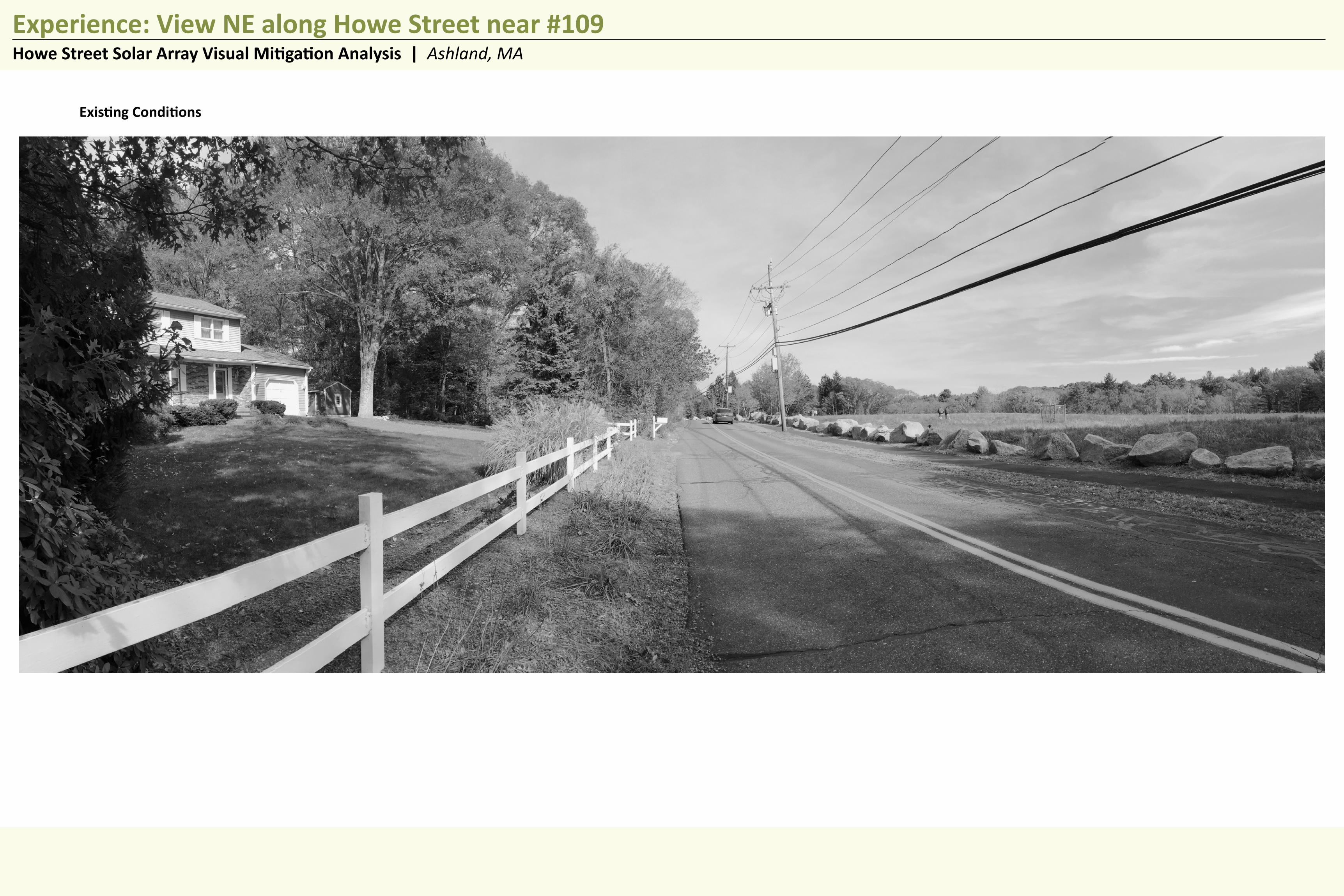
Existing Conditions
BEALS+THOMAS AMERESCO SolarPortland, ME
Experience: View NE along Howe Street near #109
DATE: 11/23/2015B+T FILE NO: 266900P002
Howe Street Solar Array Visual Mitigation Analysis | Ashland, MA

Solar Array without Mitigation
BEALS+THOMAS AMERESCO SolarPortland, MEDATE: 11/23/2015
B+T FILE NO: 266900P002
Experience: View NE along Howe Street near #101Howe Street Solar Array Visual Mitigation Analysis | Ashland, MA
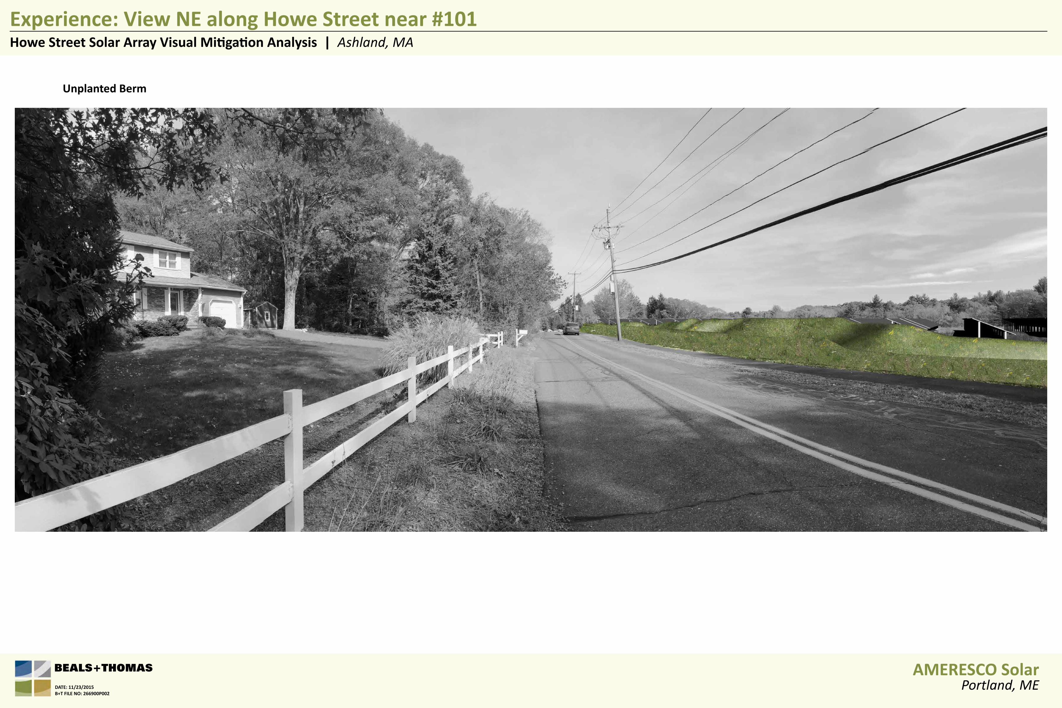
Unplanted Berm
Experience: View NE along Howe Street near #101Howe Street Solar Array Visual Mitigation Analysis | Ashland, MA
BEALS+THOMAS AMERESCO SolarPortland, MEDATE: 11/23/2015
B+T FILE NO: 266900P002
Planted Berm (looking Northwest along Howe Street)
Experience: View NE along Howe Street near #101Howe Street Solar Array Visual Mitigation Analysis | Ashland, MA
BEALS+THOMAS AMERESCO SolarPortland, MEDATE: 11/23/2015
B+T FILE NO: 266900P002

Appendix D – Solar Equipment Documentation


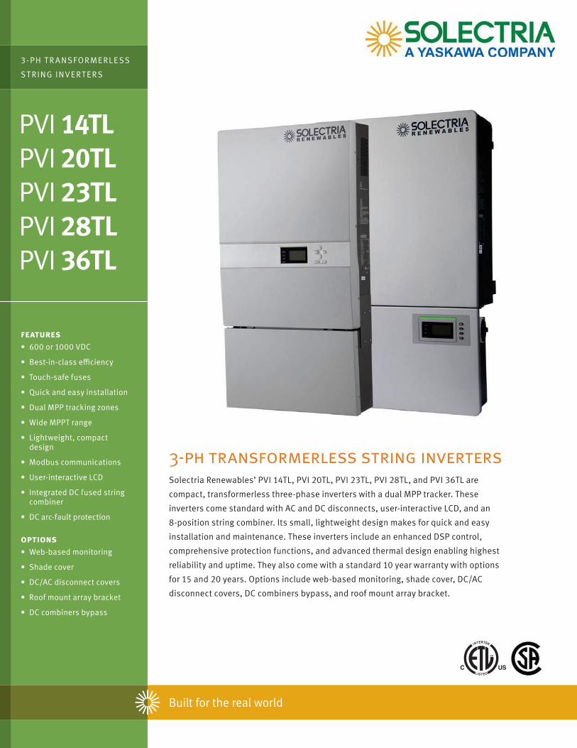
PVI 14TLPVI 20TLPVI 23TLPVI 28TLPVI 36TL
3-ph transformerless string invertersSolectria Renewables’ PVI 14TL, PVI 20TL, PVI 23TL, PVI 28TL, and PVI 36TL are
compact, transformerless three-phase inverters with a dual MPP tracker. These
inverters come standard with AC and DC disconnects, user-interactive LCD, and an
8-position string combiner. Its small, lightweight design makes for quick and easy
installation and maintenance. These inverters include an enhanced DSP control,
comprehensive protection functions, and advanced thermal design enabling highest
reliability and uptime. They also come with a standard 10 year warranty with options
for 15 and 20 years. Options include web-based monitoring, shade cover, DC/AC
disconnect covers, DC combiners bypass, and roof mount array bracket.
3-PH T R ANSFOR MERLE SS
ST RING INVERT ERS
features600 or 1000 VDC
Touch-safe fuses
Quick and easy installation
Dual MPP tracking zones
Wide MPPT range
Lightweight, compact design
Modbus communications
User-interactive LCD
Integrated DC fused string combiner
DC arc-fault protection
optionsWeb-based monitoring
Shade cover
DC/AC disconnect covers
Roof mount array bracket
DC combiners bypass
www.solectria.com | [email protected] | 978.683.9700
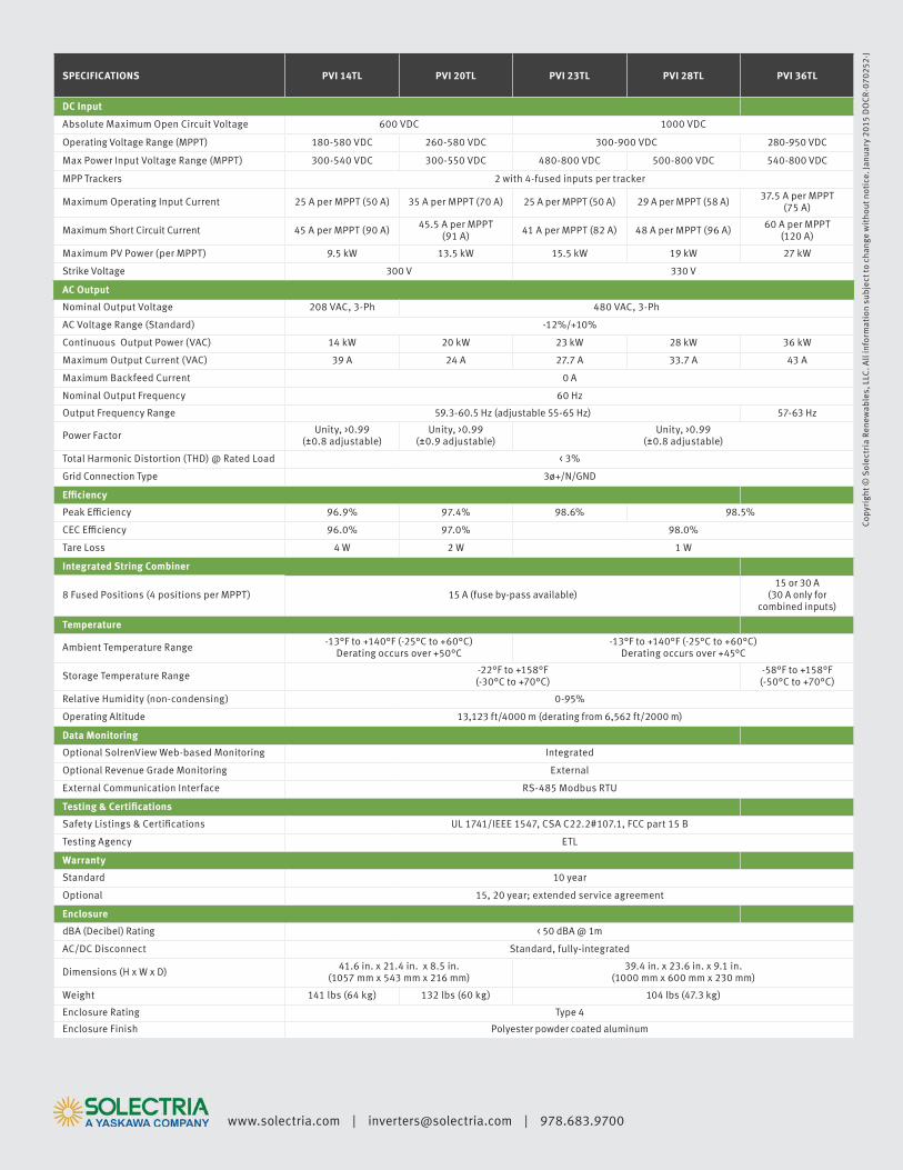
SPECIFICATIONS PVI 14TL PVI 20TL PVI 23TL PVI 28TL PVI 36TL
DC Input
Absolute Maximum Open Circuit Voltage 600 VDC 1000 VDC
Operating Voltage Range (MPPT) 180-580 VDC 260-580 VDC 300-900 VDC 280-950 VDC
Max Power Input Voltage Range (MPPT) 300-540 VDC 300-550 VDC 480-800 VDC 500-800 VDC 540-800 VDC
MPP Trackers 2 with 4-fused inputs per tracker
Maximum Operating Input Current 25 A per MPPT (50 A) 35 A per MPPT (70 A) 25 A per MPPT (50 A) 29 A per MPPT (58 A) 37.5 A per MPPT (75 A)
Maximum Short Circuit Current 45 A per MPPT (90 A) 45.5 A per MPPT (91 A) 41 A per MPPT (82 A) 48 A per MPPT (96 A) 60 A per MPPT
(120 A)
Maximum PV Power (per MPPT) 9.5 kW 13.5 kW 15.5 kW 19 kW 27 kW
Strike Voltage 300 V 330 V
AC Output
Nominal Output Voltage 208 VAC, 3-Ph 480 VAC, 3-Ph
AC Voltage Range (Standard) -12%/+10%
Continuous Output Power (VAC) 14 kW 20 kW 23 kW 28 kW 36 kW
Maximum Output Current (VAC) 39 A 24 A 27.7 A 33.7 A 43 A
Maximum Backfeed Current 0 A
Nominal Output Frequency 60 Hz
Output Frequency Range 59.3-60.5 Hz (adjustable 55-65 Hz) 57-63 Hz
Power Factor Unity, >0.99 (±0.8 adjustable)
Unity, >0.99 (±0.9 adjustable)
Unity, >0.99 (±0.8 adjustable)
Total Harmonic Distortion (THD) @ Rated Load < 3%
Grid Connection Type 3ø+/N/GND
96.9% 97.4% 98.6% 98.5%
96.0% 97.0% 98.0%
Tare Loss 4 W 2 W 1 W
8 Fused Positions (4 positions per MPPT) 15 A (fuse by-pass available)15 or 30 A
(30 A only for combined inputs)
Ambient Temperature Range -13°F to +140°F (-25°C to +60°C) Derating occurs over +50°C
-13°F to +140°F (-25°C to +60°C) Derating occurs over +45°C
Storage Temperature Range -22°F to +158°F (-30°C to +70°C)
-58°F to +158°F (-50°C to +70°C)
Relative Humidity (non-condensing) 0-95%
Operating Altitude 13,123 ft/4000 m (derating from 6,562 ft/2000 m)
Optional SolrenView Web-based Monitoring Integrated
Optional Revenue Grade Monitoring External
External Communication Interface RS-485 Modbus RTU
UL 1741/IEEE 1547, CSA C22.2#107.1, FCC part 15 B
Testing Agency ETL
Standard 10 year
Optional 15, 20 year; extended service agreement
dBA (Decibel) Rating < 50 dBA @ 1m
AC/DC Disconnect Standard, fully-integrated
Dimensions (H x W x D) 41.6 in. x 21.4 in. x 8.5 in. (1057 mm x 543 mm x 216 mm)
39.4 in. x 23.6 in. x 9.1 in. (1000 mm x 600 mm x 230 mm)
Weight 141 lbs (64 kg) 132 lbs (60 kg) 104 lbs (47.3 kg)
Enclosure Rating Type 4
Enclosure Finish Polyester powder coated aluminum
Cop
yrig
ht ©
Sol
ectr
ia R
enew
able
s, L
LC. A
ll in
form
atio
n su
bjec
t to
chan
ge w
itho
ut n
otic
e. Ja
nuar
y 20
15 D
OC
R-07
0252
-J
1
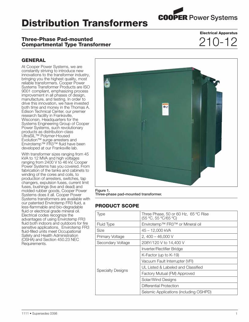
GENERALAt Cooper Power Systems, we are constantly striving to introduce new innovations to the transformer industry, bringing you the highest quality, most reliable transformers. Cooper Power Systems Transformer Products are ISO 9001 compliant, emphasizing process improvement in all phases of design, manufacture, and testing. In order to drive this innovation, we have invested both time and money in the Thomas A. Edison Technical Center, our premier research facility in Franksville, Wisconsin. Headquarters for the Systems Engineering Group of Cooper Power Systems, such revolutionary products as distribution-class UltraSIL™ Polymer-Housed Evolution™ surge arresters and Envirotemp™ FR3™ fluid have been developed at our Franksville lab.
With transformer sizes ranging from 45 kVA to 12 MVA and high voltages ranging from 2400 V to 46 kV, Cooper Power Systems has you covered. From fabrication of the tanks and cabinets to winding of the cores and coils, to production of arresters, switches, tap changers, expulsion fuses, current limit fuses, bushings (live and dead) and molded rubber goods, Cooper Power Systems does it all. Cooper Power Systems transformers are available with our patented Envirotemp FR3 fluid, a less-flammable and bio-degradable fluid or electrical grade mineral oil. Electrical codes recognize the advantages of using Envirotemp FR3 fluid both indoors and outdoors for fire sensitive applications. Envirotemp FR3 fluid-filled units meet Occupational Safety and Health Administration (OSHA) and Section 450.23 NEC Requirements.
Distribution Transformers
Three-Phase Pad-mounted Compartmental Type Transformer
Electrical Apparatus
210-12
1111 Supersedes 0398
Figure 1. Three-phase pad-mounted transformer.
Type Three Phase, 50 or 60 Hz, 65 ºC Rise (55 ºC, 55 ºC/65 ºC)
Fluid Type Envirotemp™ FR3™ or Mineral oil
Size 45 – 12,000 kVA
Primary Voltage 2, 400 – 46,000 V
Secondary Voltage 208Y/120 V to 14,400 V
Specialty Designs
Inverter/Rectifier Bridge
K-Factor (up to K-19)
Vacuum Fault Interrupter (VFI)
UL Listed & Labeled and Classified
Factory Mutual (FM) Approved
Solar/Wind Designs
Differential Protection
Seismic Applications (including OSHPD)
PRODUCT SCOPE
Three-Phase Pad-mounted Compartmental Type Transformer
2
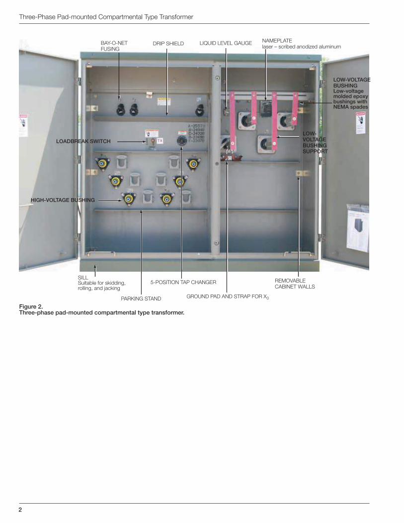
Figure 2. Three-phase pad-mounted compartmental type transformer.
LOW-VOLTAGE BUSHINGLow-voltage molded epoxy bushings with NEMA spades
LOW-VOLTAGE BUSHING SUPPORT
SILLSuitable for skidding, rolling, and jacking
LOADBREAK SWITCH
5-POSITION TAP CHANGER
GROUND PAD AND STRAP FOR X0PARKING STAND
LIQUID LEVEL GAUGENAMEPLATE
laser – scribed anodized aluminum
REMOVABLE
CABINET WALLS
DRIP SHIELDBAY-O-NET
FUSING
HIGH-VOLTAGE BUSHING

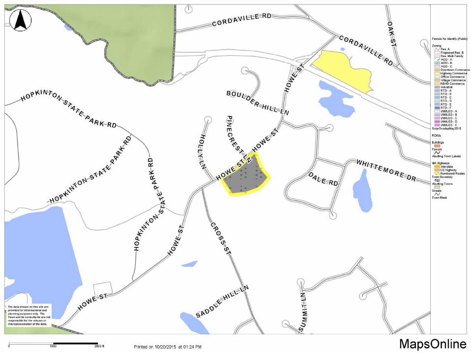
Appendix E – Zoning Maps

HIGH ST
CORDAVILLE RD
CROSS ST
WHITTEMORE DR
HOLLY LN
RAMBLEWOOD DR
INDIAN B R OOK RD
VALLEY RD
RUSSET HILL RD
BOULDER HILL LN
DALE RD
HUNTERS LN
PINECREST LN
FOX HILL RD
JOHNSON ST
BALDWIN CIR
ENDICOTT ST
OAKRIDGE LN
SANDSTONE WAY
EMPIRE CIR
HARPER LN
HOWE ST
INDIAN BROOK RD
BROGDEN RD
RIDGEWOOD ST
HIGH ST
CORDAVILLE RD
FOX HILL RD
HOWE ST
HOWE
ST
CROSS ST
GRYNCEL PARK
SUDBURY RIVER
SUDBURY RIVER
HUNTERS LN
CORDAVILLE RD
HOWE
ST
HIGH ST
WHITT
EMOR
E DRINDIAN BROOK
RD
TYDEMAN RD
28
8
2
8
7
9
7
6
2
3
3
2
1
5
5
7
5
1
5
6
4
4
8
1
9
6
1
7
8
9
183
51
3
86
9
4
2
65
29
6
4
8
8
6
3
5
16
41
9
20
70
49
53
31
29
45
65
39
43
6
19
11
60
49
73
74
12
40
56
29
32
19
4
74
11
57
10
43
111
49
38
90
110
18
20
54
24
11
70
55
67
55
10
78
36
12
13
1628
15
14
35
10
11
58
29
25
69
68
28
2
32
12
9
148
44
25 65
38
48
17
308
50
97
20
54
126
99
6115
47
48
24
40
35
45
44
5
61
39
77
55
23
61
34
66
114
98
22
106
31
128
23
54
2637
30
198
135
17
17
224
149
20
30
24
33
24
32
37
200
29
21
20
17
45
25
16
21
316318
13
53
125
23
99
39
70
16
61
34
10
28
50
84
25
120117
62
42
140
33
11
89
73
85
25
164
101
41
76
31
118
100
23
119
19
121
38
107
93
23
292
189
182
115
49
46
21
17
29
195
22
1
37
33
146
124
105
127
13
145
186
16
25
207
220
81
113
13
17
179101
142
18
105
140
21
178
17
130150
170
134
16
94
151
14
117
153
154
190
174
194
185
12
13
12
153
24
123
286
106
310
288
154
109
228
320-322
39
3860 10
321
34
2
11
04 05
17 18 19 20 21 22
06
01 02
1009
03
08
12 13 14 15 16
23 24 25 26
27 28 29 30
07
µ Information shown on this map is from the Ashland GIS database. The Town of Ashland does not guarantee the accuracy of the information.Users are responsible for determining its suitability for their intended use or purpose. Parcel lines depict approximate boundaries of land
ownership and should not be used to support any legal determination of boundaries related to rights or interests in real property.
May, 2014
12
07
18
11 13
06
1917
08
TOWN OF ASHLAND - ZONING & TAX PARCEL FY 2014
ZONING DISTRICTS
RESIDENTIAL MULTI_FAMILY RM
ADD - "C"DOWNTOWN COMMERCE CDHIGHWAY COMMERCE CHOFFICE COMMERCE CO
NEIGHBORHOOD COMMERCE CN
RTD "A"RTD "B"RTD "C"RTD "D"RTD "E"
WMUSD "C"WMUSD "D"WMUSD "E"
POND ST MIXED USE OVERLAYGROUNDWATER PROTECTION OVERLAY
kj kj kj
kj kj kj
kj kj kj SOLAR OVERLAYSURFACE WATER BODYRIVERTRAIN LINE
RESIDENTIAL
OTHER
WILDWOOD MIXED USE DISTRICT
RAIL TRANSIT DISTRICT
INDUSTRIAL
COMMERCIAL
0 200 400 600 800 1,000100 Feet
WMUSD "BUFFER"
RESIDENTIAL A RA
ADD -"A" OVERLAY
VILLAGE COMMERCE CV
WMUSD "B"WMUSD "A"
QUARRY REMEDIATION DISTRICT
TRAIN RIGHT OF WAY
BUILDINGSPARCELS
ADD - "B"
INDUSTRIAL
RTD "F"
EASEMENT
RESIDENTIAL B RB
12

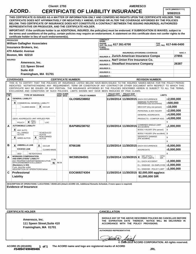
Appendix F – Liability Insurance
INSR ADDL SUBRLTR INSR WVD
DATE (MM/DD/YYYY)
PRODUCER CONTACTNAME:
FAXPHONE(A/C, No):(A/C, No, Ext):
E-MAILADDRESS:
INSURER A :
INSURED INSURER B :
INSURER C :
INSURER D :
INSURER E :
INSURER F :
POLICY NUMBERPOLICY EFF POLICY EXP
TYPE OF INSURANCE LIMITS(MM/DD/YYYY) (MM/DD/YYYY)
GENERAL LIABILITY
AUTOMOBILE LIABILITY
UMBRELLA LIAB
EXCESS LIAB
WORKERS COMPENSATIONAND EMPLOYERS' LIABILITY
DESCRIPTION OF OPERATIONS / LOCATIONS / VEHICLES (Attach ACORD 101, Additional Remarks Schedule, if more space is required)
AUTHORIZED REPRESENTATIVE
INSURER(S) AFFORDING COVERAGE NAIC #
Y / N
N / A(Mandatory in NH)
ANY PROPRIETOR/PARTNER/EXECUTIVEOFFICER/MEMBER EXCLUDED?
EACH OCCURRENCE $DAMAGE TO RENTED
COMMERCIAL GENERAL LIABILITY $PREMISES (Ea occurrence)
CLAIMS-MADE OCCUR MED EXP (Any one person) $
PERSONAL & ADV INJURY $
GENERAL AGGREGATE $
GEN'L AGGREGATE LIMIT APPLIES PER: PRODUCTS - COMP/OP AGG $
$PRO-POLICY LOCJECT
COMBINED SINGLE LIMIT$(Ea accident)
BODILY INJURY (Per person) $ANY AUTOALL OWNED SCHEDULED BODILY INJURY (Per accident) $AUTOS AUTOS
HIRED AUTOSNON-OWNED PROPERTY DAMAGE $AUTOS (Per accident)
$
OCCUR EACH OCCURRENCE $
CLAIMS-MADE AGGREGATE $
DED RETENTION $ $WC STATU- OTH-TORY LIMITS ER
E.L. EACH ACCIDENT $
E.L. DISEASE - EA EMPLOYEE $If yes, describe under
E.L. DISEASE - POLICY LIMIT $DESCRIPTION OF OPERATIONS below
SHOULD ANY OF THE ABOVE DESCRIBED POLICIES BE CANCELLED BEFORETHE EXPIRATION DATE THEREOF, NOTICE WILL BE DELIVERED INACCORDANCE WITH THE POLICY PROVISIONS.
THIS IS TO CERTIFY THAT THE POLICIES OF INSURANCE LISTED BELOW HAVE BEEN ISSUED TO THE INSURED NAMED ABOVE FOR THE POLICY PERIODINDICATED. NOTWITHSTANDING ANY REQUIREMENT, TERM OR CONDITION OF ANY CONTRACT OR OTHER DOCUMENT WITH RESPECT TO WHICH THISCERTIFICATE MAY BE ISSUED OR MAY PERTAIN, THE INSURANCE AFFORDED BY THE POLICIES DESCRIBED HEREIN IS SUBJECT TO ALL THE TERMS,EXCLUSIONS AND CONDITIONS OF SUCH POLICIES. LIMITS SHOWN MAY HAVE BEEN REDUCED BY PAID CLAIMS.
THIS CERTIFICATE IS ISSUED AS A MATTER OF INFORMATION ONLY AND CONFERS NO RIGHTS UPON THE CERTIFICATE HOLDER. THISCERTIFICATE DOES NOT AFFIRMATIVELY OR NEGATIVELY AMEND, EXTEND OR ALTER THE COVERAGE AFFORDED BY THE POLICIESBELOW. THIS CERTIFICATE OF INSURANCE DOES NOT CONSTITUTE A CONTRACT BETWEEN THE ISSUING INSURER(S), AUTHORIZEDREPRESENTATIVE OR PRODUCER, AND THE CERTIFICATE HOLDER.
IMPORTANT: If the certificate holder is an ADDITIONAL INSURED, the policy(ies) must be endorsed. If SUBROGATION IS WAIVED, subject tothe terms and conditions of the policy, certain policies may require an endorsement. A statement on this certificate does not confer rights to thecertificate holder in lieu of such endorsement(s).
COVERAGES CERTIFICATE NUMBER: REVISION NUMBER:
CERTIFICATE HOLDER CANCELLATION
© 1988-2010 ACORD CORPORATION. All rights reserved.
The ACORD name and logo are registered marks of ACORDACORD 25 (2010/05)
ACORDTM CERTIFICATE OF LIABILITY INSURANCE 9/08/2015
William Gallagher AssociatesInsurance Brokers, Inc.470 Atlantic AvenueBoston, MA 02210
617 261-6700 617-646-0400
Ameresco, Inc.111 Speen StreetSuite 410Framingham, MA 01701
Zurich-American Insurance CompaNat'l Union Fire Insurance Co. Steadfast Insurance Company
27855
26387
AX
X
X
GLO585238802 11/30/2014 11/30/2015 2,000,000500,00010,0002,000,0004,000,0004,000,000
AX
X X
BAP585238702 11/30/2014 11/30/2015 1,000,000
B X X 8766186 11/30/2014 11/30/2015 5,000,0005,000,000
A
N
WC595394501 11/30/2014 11/30/2015 X1,000,000
1,000,0001,000,000
C ProfessionalLiability
EOC669274304 11/30/2014 11/30/2015 $2,000,000 agg/occ$1,000,000 SIR
Evidence of Insurance
Ameresco, Inc.111 Speen Street,Suite 410Framingham, MA 01701
1 of 1#S489474/M489466
AMERESCOClient#: 2793
JRL1 of 1
#S489474/M489466

Appendix G – Operation and Maintenance Plan
PV Projects Operational and
Maintenance Service Procedures
Integrity ■ Flexibility ■ Independence ■ Innovation
Main Office: 111 Speen Street, Suite 410 Framingham, MA 01701
Phone: (508) 661-2256 Fax: (508) 661-2201
“Page content is subject to Confidentiality Restrictions”
PV Projects Operational and Maintenance Service Procedures August 13, 2012 Page i
Table of Contents
Introduction __________________________________________________________________ 1
Equipment Operational and Acceptance Dates _______________________________________ 2
AMERESCO Annual Operations and Maintenance Checklist- PV Systems________________ 3-7
AMERESCO Service Delievery System (ASDS) Service and Maintenance Procedures _____ 8
“Page content is subject to Confidentiality Restrictions”
PV Projects Operational and Maintenance Service Procedures August 13, 2012 Page 1
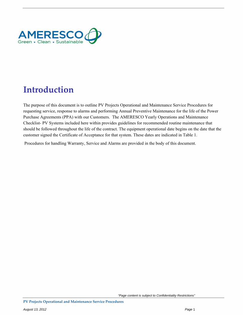
Introduction
The purpose of this document is to outline PV Projects Operational and Maintenance Service Procedures for requesting service, response to alarms and performing Annual Preventive Maintenance for the life of the Power Purchase Agreements (PPA) with our Customers. The AMERESCO Yearly Operations and Maintenance Checklist- PV Systems included here within provides guidelines for recommended routine maintenance that should be followed throughout the life of the contract. The equipment operational date begins on the date that the customer signed the Certificate of Acceptance for that system. These dates are indicated in Table 1.
Procedures for handling Warranty, Service and Alarms are provided in the body of this document.
“Page content is subject to Confidentiality Restrictions”
PV Projects Operational and Maintenance Service Procedures August 13, 2012 Page 2
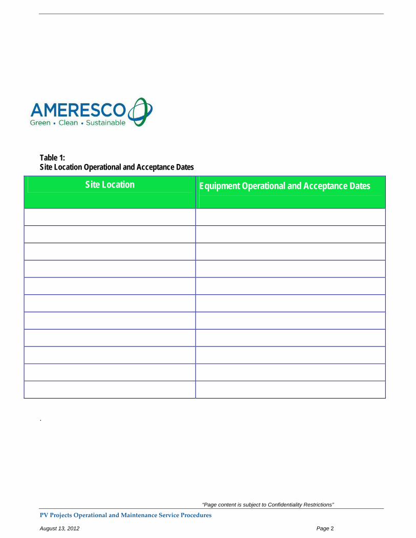
Table 1: Site Location Operational and Acceptance Dates
Site Location Equipment Operational and Acceptance Dates
.
“Page content is subject to Confidentiality Restrictions”
PV Projects Operational and Maintenance Service Procedures August 13, 2012 Page 3
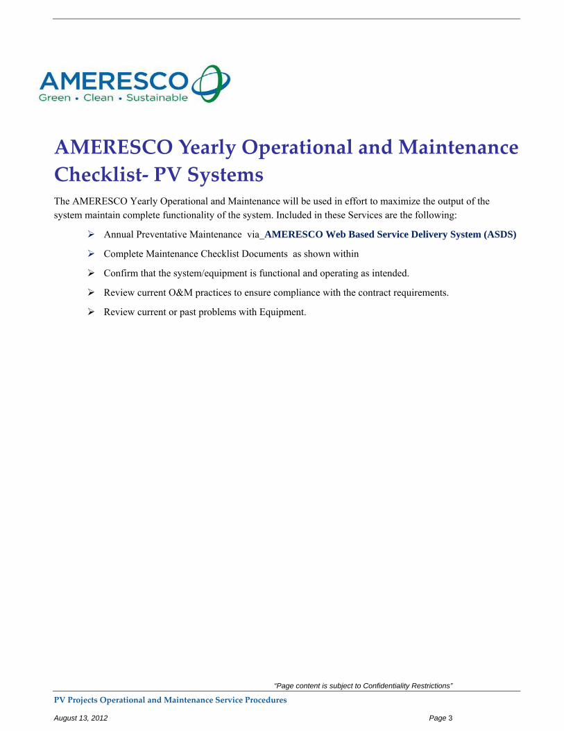
AMERESCO Yearly Operational and Maintenance
Checklist‐ PV Systems The AMERESCO Yearly Operational and Maintenance will be used in effort to maximize the output of the system maintain complete functionality of the system. Included in these Services are the following:
Annual Preventative Maintenance via AMERESCO Web Based Service Delivery System (ASDS)
Complete Maintenance Checklist Documents as shown within
Confirm that the system/equipment is functional and operating as intended.
Review current O&M practices to ensure compliance with the contract requirements.
Review current or past problems with Equipment.
“Page content is subject to Confidentiality Restrictions”
PV Projects Operational and Maintenance Service Procedures August 13, 2012 Page 4
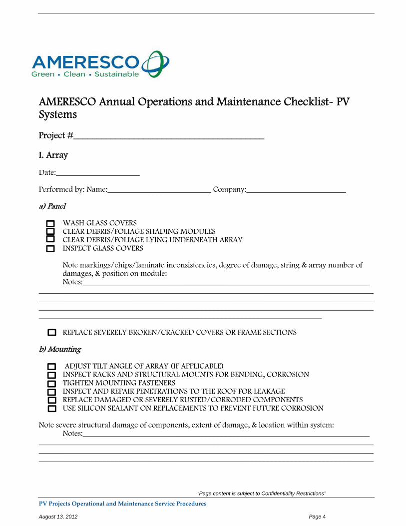
AMERESCO Annual Operations and Maintenance Checklist- PV Systems Project #_________________________________________ I. Array Date:_____________________ Performed by: Name:__________________________ Company:_________________________ a) Panel
WASH GLASS COVERS CLEAR DEBRIS/FOLIAGE SHADING MODULES CLEAR DEBRIS/FOLIAGE LYING UNDERNEATH ARRAY INSPECT GLASS COVERS
Note markings/chips/laminate inconsistencies, degree of damage, string & array number of damages, & position on module: Notes:________________________________________________________________________
___________________________________________________________________________________________________________________________________________________________________________________________________________________________________________________________________________________________________________________________________ REPLACE SEVERELY BROKEN/CRACKED COVERS OR FRAME SECTIONS b) Mounting ADJUST TILT ANGLE OF ARRAY (IF APPLICABLE) INSPECT RACKS AND STRUCTURAL MOUNTS FOR BENDING, CORROSION TIGHTEN MOUNTING FASTENERS INSPECT AND REPAIR PENETRATIONS TO THE ROOF FOR LEAKAGE REPLACE DAMAGED OR SEVERELY RUSTED/CORRODED COMPONENTS USE SILICON SEALANT ON REPLACEMENTS TO PREVENT FUTURE CORROSION Note severe structural damage of components, extent of damage, & location within system:
Notes:____________________________________________________________________________________________________________________________________________________________________________________________________________________________________________________________________________________________________________________________________
“Page content is subject to Confidentiality Restrictions”
PV Projects Operational and Maintenance Service Procedures August 13, 2012 Page 5
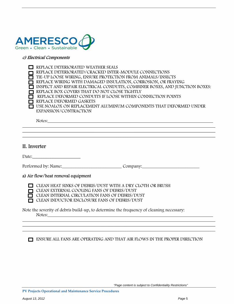
c) Electrical Components REPLACE DETERIORATED WEATHER SEALS REPLACE DETERIORATED/CRACKED INTER-MODULE CONNECTIONS TIE-UP LOOSE WIRING, ENSURE PROTECTION FROM ANIMALS/INSECTS REPLACE WIRING WITH DAMAGED INSULATION, CORROSION, OR FRAYING INSPECT AND REPAIR ELECTRICAL CONDUITS, COMBINER BOXES, AND JUNCTION BOXES: REPLACE BOX COVERS THAT DO NOT CLOSE TIGHTLY REPLACE DEFORMED CONDUITS IF LOOSE WITHIN CONNECTION POINTS REPLACE DEFORMED GASKETS USE NOALOX ON REPLACEMENT ALUMINUM COMPONENTS THAT DEFORMED UNDER
EXPANSION/CONTRACTION Notes:________________________________________________________________________
____________________________________________________________________________________________________________________________________________________________________________________________________________________________________________________________
II. Inverter Date:_____________________ Performed by: Name:__________________________ Company:_________________________ a) Air flow/heat removal equipment CLEAN HEAT SINKS OF DEBRIS/DUST WITH A DRY CLOTH OR BRUSH CLEAN EXTERNAL COOLING FANS OF DEBRIS/DUST CLEAN INTERNAL CIRCULATION FANS OF DEBRIS/DUST CLEAN INDUCTOR ENCLOSURE FANS OF DEBRIS/DUST Note the severity of debris build-up, to determine the frequency of cleaning necessary:
Notes:____________________________________________________________________________________________________________________________________________________________________________________________________________________________________________________________________________________________________________________________________ ENSURE ALL FANS ARE OPERATING AND THAT AIR FLOWS IN THE PROPER DIRECTION
“Page content is subject to Confidentiality Restrictions”
PV Projects Operational and Maintenance Service Procedures August 13, 2012 Page 6
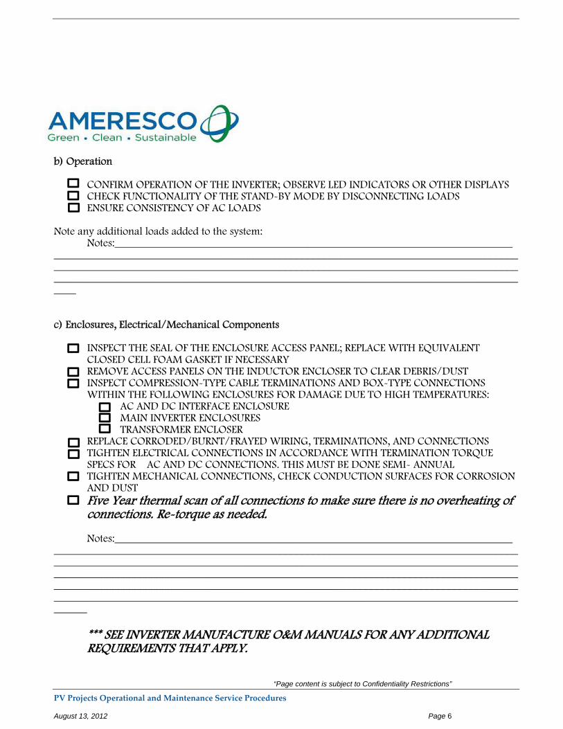
b) Operation CONFIRM OPERATION OF THE INVERTER; OBSERVE LED INDICATORS OR OTHER DISPLAYS CHECK FUNCTIONALITY OF THE STAND-BY MODE BY DISCONNECTING LOADS ENSURE CONSISTENCY OF AC LOADS Note any additional loads added to the system:
Notes:________________________________________________________________________________________________________________________________________________________________________________________________________________________________________________________________________________________________________________________________________ c) Enclosures, Electrical/Mechanical Components INSPECT THE SEAL OF THE ENCLOSURE ACCESS PANEL; REPLACE WITH EQUIVALENT
CLOSED CELL FOAM GASKET IF NECESSARY REMOVE ACCESS PANELS ON THE INDUCTOR ENCLOSER TO CLEAR DEBRIS/DUST INSPECT COMPRESSION-TYPE CABLE TERMINATIONS AND BOX-TYPE CONNECTIONS
WITHIN THE FOLLOWING ENCLOSURES FOR DAMAGE DUE TO HIGH TEMPERATURES: AC AND DC INTERFACE ENCLOSURE MAIN INVERTER ENCLOSURES TRANSFORMER ENCLOSER REPLACE CORRODED/BURNT/FRAYED WIRING, TERMINATIONS, AND CONNECTIONS
TIGHTEN ELECTRICAL CONNECTIONS IN ACCORDANCE WITH TERMINATION TORQUE SPECS FOR AC AND DC CONNECTIONS. THIS MUST BE DONE SEMI- ANNUAL TIGHTEN MECHANICAL CONNECTIONS, CHECK CONDUCTION SURFACES FOR CORROSION AND DUST
Five Year thermal scan of all connections to make sure there is no overheating of connections. Re-torque as needed. Notes:________________________________________________________________________
__________________________________________________________________________________________________________________________________________________________________________________________________________________________________________________________________________________________________________________________________________________________________________________________________________________________________________
*** SEE INVERTER MANUFACTURE O&M MANUALS FOR ANY ADDITIONAL REQUIREMENTS THAT APPLY.

“Page content is subject to Confidentiality Restrictions”
PV Projects Operational and Maintenance Service Procedures August 13, 2012 Page 7
III. Grounding Maintenance Date:_____________________ Performed by: Name:__________________________ Company:_________________________ CONFIRM GROUNDING OF ALL EQUIPMENT. THE FOLLOWING EXPOSED NON-CURRENT-
CARRYING METALS SHOULD BE GROUNDED TOGETHER TO AN EARTH GROUND ROD: FRAMES/RACKS CONDUITS JUNCTION/COMBINER BOXES USE AN OHMMETER TO CONFIRM ALL SYSTEM COMPONENTS ARE PROPERLY ATTACHED
TO THE GROUNDING LINE INSPECT GROUNDING LUGS; CHECK FOR CORROSION AND APPLY NOALOX AS NEEDED INSPECT EXPOSED COPPER CONDUCTORS FOR SIGNS OF SERIOUS CORROSION AND
OXIDIZATION THE GROUNDING CONDUCTOR SHOULD BE COLORED WHITE, THE EQUIPMENT
GROUNDING WIRE SHOUD BE GREEN OR BARE
IV. Site Inspection / Maintenance (To be performed semi-annually for ground mount
and landfill installations) Date: __________________ Performed by: Name: _____________________________ Company:______________________
INSPECT ALL SECURITY FENCING INCLUDING GATES AND LOCKING MECHANISMS. NOTE ANY DEFECTS THAT COULD IMPACT THE SECURITY OF THE SITE.
INSPECT ALL WARNING SIGNAGE AROUND THE PERIMETER OF THE SITE TO ENSURE IT IS PROPERLY SECURED TO THE FENCE/GATES AND IS CLEARLY VISIBLE AND LEGIBLE.
WALK EAST TO WEST ALONG EACH INTER-ARRAY PATHWAY CHECKING FOR INDICATIONS OF UNEVEN LOCALIZED SETTLEMENT, EROSION OF THE TOPSOIL OR VEGETATIVE LAYER AND/OR EXPOSURE OF THE IMPERVIOUS (CLAY) CAP OR MEMBRANE MATERIAL. NOTE ANY/ALL AREAS OF CONCERN ON THE SITE PLAN.
MOW VEGETATIVE COVER INSIDE THE ENCLOSED (FENCED) AREA AND EXTENDING 3 FT. OUTSIDE THE FENCE AS NECESSARY TO MAINTAIN A MAXIMUM HEIGHT OF 24 INCHES ABOVE FINISHED GRADE AND TO ELIMINATE ANY/ALL SHADING OF THE PV MODULES.
CUT ANY/ALL VINES/PLANTS GROWING ON THE SECURITY FENCE/GATES AND APPLY AN APPROVED VEGETATION RETARDANT ALONG THE LENGTH OF THE FENCE/GATES AS NECESSARY TO INHIBIT CONTINUED PLANT GROWTH.
“Page content is subject to Confidentiality Restrictions”
PV Projects Operational and Maintenance Service Procedures August 13, 2012 Page 8
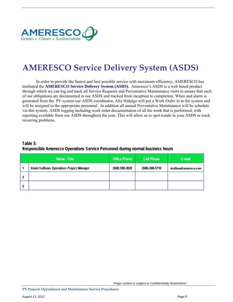
AMERESCO Service Delivery System (ASDS)
In order to provide the fastest and best possible service with maximum efficiency, AMERESCO has instituted the AMERESCO Service Delivery System (ASDS). Ameresco’s ASDS is a web based product through which we can log and track all Service Requests and Preventative Maintenance visits to ensure that each of our obligations are documented in our ASDS and tracked from inception to completion. When and alarm is generated from the PV system our ASDS coordinator, Alix Hidalgo will put a Work Order in to the system and will be assigned to the appropriate personnel. In addition all annual Preventative Maintenance will be schedule via this system. ASDS logging including work order documentation of all the work that is performed, with reporting available from our ASDS throughout the year. This will allow us to spot trends in your ASDS or track recurring problems.
Table 3: Responsible Ameresco Operations Service Personnel during normal business hours
Name –Title Office Phone Cell Phone E-mail
1 Kevin Sullivan- Operations Project Manager (508) 598-3028 (508)-308-5710 [email protected]
2
3

Appendix H – Consultation with Eversource
Exhibit G - Interconnection Service Agreement
1. Parties. This Interconnection Service Agreement (“Agreement”), dated as of August 18, 2015 (“Effective Date”) is entered into, by and between Eversource, a Massachusetts corporation with a principal place of business at One NSTAR Way, Westwood, MA 02090 (hereinafter referred to as the “Company”), and Ashland Howe St Solar LLC. a corporation with a principal place of business at 111 Speen St, Suite 410, Framingham, MA 01701 (“Interconnecting Customer”). (The Company and Interconnecting Customer are collectively referred to as the “Parties”). Terms used herein without definition shall have the meanings set forth in Section 1.2 of the Interconnection Tariff which is hereby incorporated by reference. WO#2071039, 728 kW
2. Basic Understandings. This Agreement provides for parallel operation of an Interconnecting Customer’s Facility with the Company EPS to be installed and operated by the Interconnecting Customer at Howe Street, Ashland, MA 01721 Acct# 2932-533-0016 (Facility name, address, and end-use Customer account number, if applicable). A description of the Facility is located in Attachment 1. If the Interconnecting Customer is not the Customer, an Agreement between the Company and the Company’s Retail Customer, attached as Exhibit H to the Interconnection Tariff, must be signed and included as an Attachment to this Agreement. If neither the Interconnecting Customer nor the Customer is the Landowner of the property where the Facility is sited, a Landowner Consent Agreement, attached as Exhibit I to the Interconnection Tariff, must be signed and included as an Attachment to this Agreement, unless the Company, in its sole discretion, waives this requirement.
The Interconnecting Customer has the right to operate its Facility in parallel with the Company EPS immediately upon successful completion of the protective relays testing as witnessed by the Company and receipt of written notice from the Company that interconnection with the Company EPS is authorized (“Authorization Date”).
3. Term. This Agreement shall become effective as of the Effective Date. The Agreement shall continue in full force and effect until terminated pursuant to Section 4 of this Agreement.
4. Termination.
This Agreement may be terminated under the following conditions.
4.1 a) The Parties agree in writing to terminate the Agreement.
The Interconnecting Customer may terminate this agreement at any time by providing sixty (60) days written notice to Company.
The Company may terminate this Agreement upon the occurrence of an Event of Default by the Interconnecting Customer as provided in Section 18 of this Agreement.
One NSTAR Way Westwood, Massachusetts 02090
The Company may terminate this Agreement if the Interconnecting Customer either: (1) fails to energize the Facility within 12 months of the Authorization Date; or, (2) permanently abandons the Facility. Failure to operate the Facility for any consecutive 12 month period after the Authorization Date shall constitute permanent abandonment unless otherwise agreed to in writing between the Parties.
The Company, upon 30 days notice, may terminate this Agreement if there are any changes in Department regulations or state law that have a material adverse effect on the Company’s ability to perform its obligations under the terms of this Agreement.
Survival of Obligations. The termination of this Agreement shall not relieve either Party of its liabilities and obligations, owed or continuing at the time of termination. Sections 5, 10, 12, 13, and 25 as it relates to disputes pending or for wrongful termination of this Agreement shall survive the termination of this Agreement.
Related Agreements. Any agreement attached to and incorporated into this Agreement shall terminate concurrently with this Agreement unless the Parties have agreed otherwise in writing. If the Interconnection Service Agreement is signed prior to a Detailed Study (if applicable), the System Modifications construction schedule from the Detailed Study when finalized shall be deemed a part of the signed Interconnection Service Agreement.
5. General Payment Terms. The Interconnecting Customer shall be responsible for the System Modification costs and payment terms identified in Attachment 3of this Agreement and any approved cost increases pursuant to the terms of the Interconnection Tariff. Interconnecting Customers shall not be required to pay any costs related to Company infrastructure upgrades or System Modifications upon execution of the Interconnection Service Agreement (or once the Interconnecting Customer receives the construction schedule). Interconnecting Customers shall have 120 Business Days from the date of execution of an Interconnection Service Agreement to pay 25 percent of those costs;if an Interconnecting Customer pays such cost within the 120 Business Day Time Frame, the Interconnecting Customer shall have an additional 120 Business Days from the date of first payment to pay the remainder of the costs. If the system modifications exceed $25,000, the Interconnecting Customer is eligible for a payment plan, including a payment and construction schedule with milestones for both parties, and any such payment plan shall be set forth in Attachment 3. The payment plan may include a payment schedule different than the 120 Business Day payment schedule requirements set forth in this paragraph above.
Construction estimates are valid for 60 Business Days from when they are delivered to the Interconnecting Customer. If an Interconnecting Customer payment is not received within 60 Business Days of receiving the Interconnection Service Agreement in the Expedited Process, or the Impact Study in the Standard Process, the Company has the right to reassess construction costs and Time Frames. In the event that the Interconnecting Customer fails to pay the Company within the Time Frame required by this provision, the Company will require the Interconnecting Customer to reapply for interconnection. Further, any fees paid will not be refunded. The construction schedule will commence once the Interconnecting

Customer’s financial payment has been made in fullor as otherwise provided in Attachment 3. The Company’s obligation to the construction schedule (as it appears in either the Interconnection Service Agreement or the Detailed Study, if the Interconnecting Customer has opted to sign the Interconnection Service Agreement without a Detailed Study) begins on the next Business Day after the Company receives full payment for such construction or as otherwise provided in Attachment 3.
Cost or Fee Adjustment Procedures.
The Company will, in writing, advise the Interconnecting Customer in advance of any cost increase for work to be performed up to a total amount of increase of 10% only. Interconnecting Customers who elected to execute an Interconnection Services Agreement following the completion of the Impact Study but prior to the commencement of any required Detailed Study, pursuant to Section 3.4(g) of the Interconnection Tariff, shall be responsible for any System Modifications costs, ±25%, as identified by the Company in the Impact Study.All costs that exceed the above caps will be borne solely by the Company. Any such changes to the Company’s costs for the work shall be subject to the Interconnecting Customer’s consent. The Interconnecting Customer shall, within thirty (30) Business Days of the Company’s notice of increase, authorize such increase and make payment in the amount up to the above caps, or the Company will suspend the work and the corresponding agreement will terminate.
Final Accounting.
An Interconnecting Customer may request a final accounting report of any difference between (a) Interconnecting Customer’s cost responsibility under this Agreement for the actual cost of the System Modifications, and (b) Interconnecting Customer’s previous aggregate payments to the Company under the Interconnection Service Agreement for such System Modifications within 120 Business days after completion of the construction and installation of the System Modifications described in an attached exhibit to the Interconnection Service Agreement. Upon receipt of such a request from an Interconnecting Customer, the Company shall have 120 Business days to provide the requested final accounting report to the Interconnecting Customer. To the extent that Interconnecting Customer’s cost responsibility in the Interconnection Service Agreement exceeds Interconnecting Customer’s previous aggregate payments, the Company shall invoice Interconnecting Customer and Interconnecting Customer shall make payment to the Company within 45 Business Days. To the extent that Interconnecting Customer’s previous aggregate payments exceed Interconnecting Customer’s cost responsibility under this agreement, the Company shall refund to Interconnecting Customer an amount equal to the difference within forty five (45) Business Days of the provision of such final accounting report.
6. Operating Requirements.
General Operating Requirements.
Interconnecting Customer shall operate and maintain the Facility in accordance with the applicable manufacturer’s recommended maintenance schedule, in compliance with all aspects of the Company’s Interconnection Tariff. The Interconnecting Customer will continue to comply with all applicable laws and requirements after interconnection has occurred. In the event the Company has reason to believe that the Interconnecting Customer’s installation may be the source of problems on the Company EPS, the Company has the right to install monitoring equipment at a mutually agreed upon location to determine the source of the problems. If the Facility is determined to be the source of the problems, the Company may require disconnection as outlined in Section 7.0 of this Interconnection Tariff. The cost of this testing will be borne by the Company unless the Company demonstrates that the problem or problems are caused by the Facility or if the test was performed at the request of the Interconnecting Customer.
No Adverse Effects; Non-interference.
Company shall notify Interconnecting Customer if there is evidence that the operation of the Facility could cause disruption or deterioration of service to other Customers served from the same Company EPS or if operation of the Facility could cause damage to Company EPS or Affected Systems. The deterioration of service could be, but is not limited to, harmonic injection in excess of IEEE Standard 1547-2003, as well as voltage fluctuations caused by large step changes in loading at the Facility. Each Party will notify the other of any emergency or hazardous condition or occurrence with its equipment or facilities which could affect safe operation of the other Party’s equipment or facilities. Each Party shall use reasonable efforts to provide the other Party with advance notice of such conditions.
The Company will operate the EPS in such a manner so as to not unreasonably interfere with the operation of the Facility. The Interconnecting Customer will protect itself from normal disturbances propagating through the Company EPS, and such normal disturbances shall not constitute unreasonable interference unless the Company has deviated from Good Utility Practice. Examples of such disturbances could be, but are not limited to, single-phasing events, voltage sags from remote faults on the Company EPS, and outages on the Company EPS. If the Interconnecting Customer demonstrates that the Company EPS is adversely affecting the operation of the Facility and if the adverse effect is a result of a Company deviation from Good Utility Practice, the Company shall take appropriate action to eliminate the adverse effect.

Safe Operations and Maintenance.
Each Party shall operate, maintain, repair, and inspect, and shall be fully responsible for, the facility or facilities that it now or hereafter may own unless otherwise specified in this Agreement. Each Party shall be responsible for the maintenance, repair and condition of its respective lines and appurtenances on their respective side of the PCC. The Company and the Interconnecting Customer shall each provide equipment on its respective side of the PCC that adequately protects the Company’s EPS, personnel, and other persons from damage and injury.
Access.
The Company shall have access to the disconnect switch of the Facility at all times.
6.4 a) Company and Interconnecting Customer Representatives.
Each Party shall provide and update as necessary the telephone number that can be used at all times to allow either Party to report an emergency.
6.4 b) Company Right to Access Company-Owned Facilities and Equipment.
If necessary for the purposes of the Interconnection Tariff and in the manner it describes, the Interconnecting Customer shall allow the Company access to the Company’s equipment and the Company’s facilities located on the Interconnecting Customer’s or Customer’s premises. To the extent that the Interconnecting Customer does not own all or any part of the property on which the Company is required to locate its equipment or facilities to serve the Interconnecting Customer under the Interconnection Tariff, the Interconnecting Customer shall secure and provide in favor of the Company the necessary rights to obtain access to such equipment or facilities, including easements if the circumstances so require. In addition to any rights and easements required by the Company in accordance with the above provision, the Interconnecting Customer shall obtain an executed Landowner Consent Agreement (Exhibit I) from the Landowner, unless the Company, in its sole discretion, waives this requirement.
6.4 c) Right to Review Information.
The Company shall have the right to review and obtain copies of Interconnecting Customer’s operations and maintenance records, logs, or other information such as, unit availability, maintenance outages, circuit breaker operation requiring manual reset, relay targets and unusual events pertaining to Interconnecting Customer’s Facility or its interconnection


