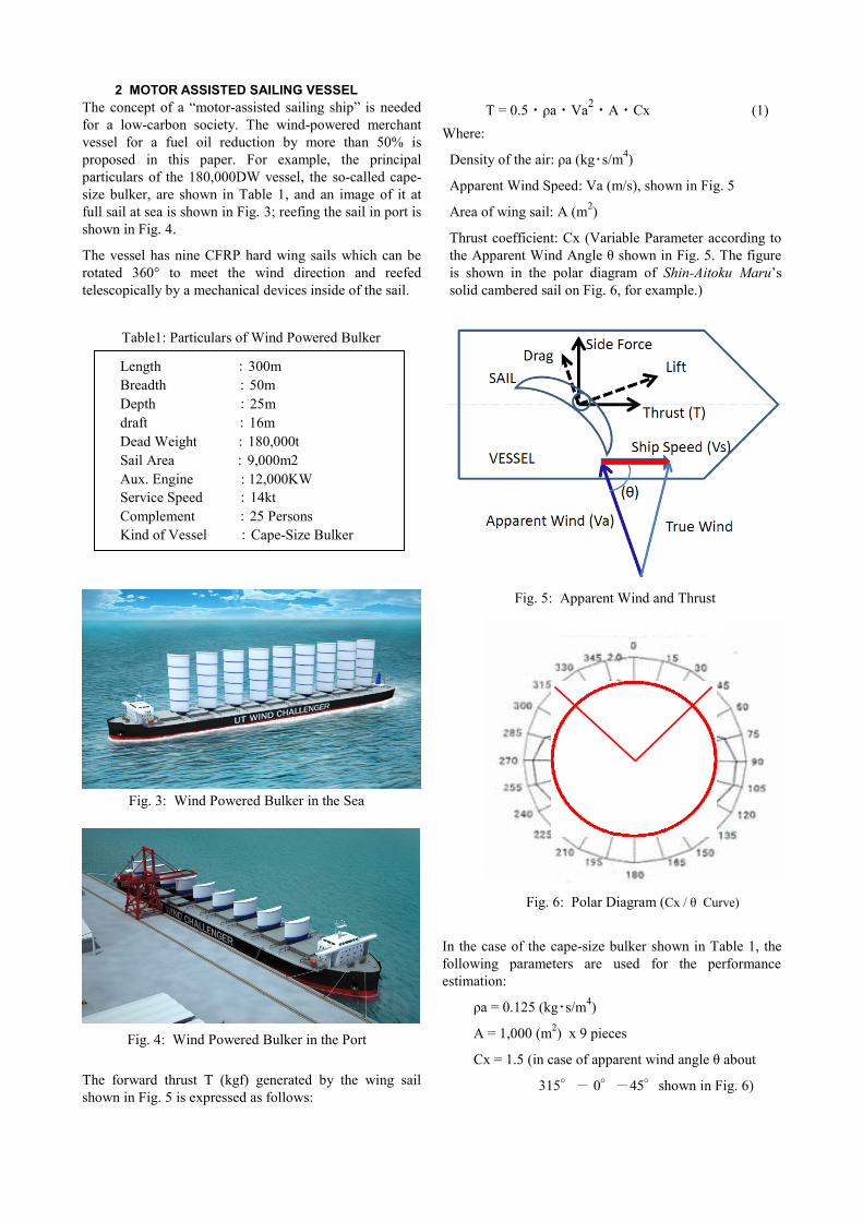
Second International Symposium on Marine Propulsors smp’11, Hamburg, Germany, June 2011 Huge Hard Wing Sails for the Propulsor of Next Generation Sailing Vessel * Kazuyuki Ouchi 1 , Kiyoshi Uzawa 1 and Akihiro Kanai 2 1 Graduate School of Engineering, The University of Tokyo, Japan 2 ACT Corporation, Japan ABSTRACT To drastically reduce the fuel oil consumption of a large merchant vessel, the utilization of ocean wind power should be considered as an option for the main propulsion power of the vessel. The new concept of “motor-assisted sailing ship” is proposed as an excellent eco-ship towards a low-carbon society. The vessel is fitted with huge hard sails (height: 50m, breadth: 20m, area: 1,000m 2 x9) on the upper deck as a main propulsor, which is made by CFRP composite. The hard sail has a crescent wing section, and also has a vertically telescopic reefing mechanism and a self-rotating mechanism to meet the wind direction. The nine pieces of hard sails (total sail area 9,000m 2 ) are expected to generate enough forward thrust to drive a 180,000DWT bulk carrier on 14knot, in case of wind velocity of 12m/s from a beam. The aerodynamic interaction of the 9 wing row sail system is carried out with a full scale CFD simulation. Furthermore, a case study on the effect of “motor-assisted sailing ship” in the real sea was carried out and more than 50% of propulsion energy is acquired from the ocean wind power in average. Keywords Eco-Ship, Energy Saving, Wind Power, Sailing Vessel, Hard Sail, CFRP, Composite 1 INTRODUCTION In order to move toward the era of a low-carbon society, it is necessary to drastically reduce CO2 emissions from large ocean-going merchant vessels that are burning fossil oil. However, it may be impossible to reduce fossil fuel use by more than 50% in the case of same speed and deadweight. Thus, a change of energy source for ship propulsion is absolutely needed for the next generation of merchant vessels. The candidates would be driven by wind, nuclear energy, fuel cells, battery, bio-fuel, CCS (carbon-dioxide capture and storage), etc. From the viewpoint of sustainability and free energy costs, it is clear that ocean wind power is the best solution to drive slow-speed vehicles, such as a very large merchant vessel. For reducing the fuel oil consumption of a ship, it is recommendable and even important to make use of wind power at sea. We should take into account the sailing ship, whose concept is not only suitable for a low-carbon society but one which also meets the requirements of current global logistics, when developing the ship. Following the demise of traditional sailing merchant ships in the beginning of 20th century, very few modern sailing ships have come to replace them. The Shin-Aitoku Maru shown in Fig. 1, which has cambered hard sails made of metallic board, was developed by JAMDA Japan in the 1970s as one of the great challenges for a new concept sailing vessel (Endo et al 1982). Fig. 2 shows Beluga Sky Sail, which is a kind of kite developed in Germany last year. Both technologies seem to be categorized as a “sail- assisted motor ship”, and the reduction of fuel oil consumption is about 10% in mean value during one year. Fig. 1: Shin-Aitoku Maru Fig. 2: Beluga Skysail
Transcript
Second International Symposium on Marine Propulsors smp’11, Hamburg, Germany, June 2011
Huge Hard Wing Sails for the Propulsor of Next Generation Sailing Vessel *
Kazuyuki Ouchi1, Kiyoshi Uzawa
1 and Akihiro Kanai
2
1 Graduate School of Engineering, The University of Tokyo, Japan
2 ACT Corporation, Japan
ABSTRACT
To drastically reduce the fuel oil consumption of a large
merchant vessel, the utilization of ocean wind power
should be considered as an option for the main propulsion
power of the vessel. The new concept of “motor-assisted
sailing ship” is proposed as an excellent eco-ship towards
a low-carbon society. The vessel is fitted with huge hard
sails (height: 50m, breadth: 20m, area: 1,000m2x9) on the
upper deck as a main propulsor, which is made by CFRP
composite. The hard sail has a crescent wing section, and
also has a vertically telescopic reefing mechanism and a
self-rotating mechanism to meet the wind direction. The
nine pieces of hard sails (total sail area 9,000m2) are
expected to generate enough forward thrust to drive a
180,000DWT bulk carrier on 14knot, in case of wind
velocity of 12m/s from a beam. The aerodynamic
interaction of the 9 wing row sail system is carried out
with a full scale CFD simulation. Furthermore, a case
study on the effect of “motor-assisted sailing ship” in the
real sea was carried out and more than 50% of propulsion
energy is acquired from the ocean wind power in average.
Keywords
Eco-Ship, Energy Saving, Wind Power, Sailing Vessel,
Hard Sail, CFRP, Composite
1 INTRODUCTION
In order to move toward the era of a low-carbon society,
it is necessary to drastically reduce CO2 emissions from
large ocean-going merchant vessels that are burning fossil
oil. However, it may be impossible to reduce fossil fuel
use by more than 50% in the case of same speed and
deadweight. Thus, a change of energy source for ship
propulsion is absolutely needed for the next generation of
merchant vessels. The candidates would be driven by