< Safety in Dock > 10. Rudder The rudder is the most important part of the ship. If the rudder becomes defective, the ship can no longer operate, even though the condition of the hull and machinery is satisfactory. Similar to the propeller, the rudder is normally immersed under water, therefore, details of its condition can be observed only during a bottom inspection when the ship is docked. Inspection of the rudder also includes inspection of deformation, checking for cracks and the condition of rudder bearing wear down. 10-1 Type of rudder There are many types in rudder. The followings are the typical examples . Fig.10-1 hanging ridder Fig.10-2 Symplex rudder Fig.10-3 Rudder with one pintle Fig.10-4 Mariner rudder 1.Introduction 2.Docking Survey 3.Survey Item 4.Type of Dry Dock 5.Safety in Dock 6.Procedure of Bottom Inspection 7.Course in Dock 8.Shell Defect 9.Stern Frame 10.Rudder 11.Propeller 12.Anchr 13.Chain Cable 14.Sea Valves Hull Survey welcome to
Transcript
< Safety in Dock >
10. RudderThe rudder is the most important part of the ship. If the rudder becomes defective, theship can no longer operate, even though the condition of the hull and machinery issatisfactory. Similar to the propeller, the rudder is normally immersed under water,therefore, details of its condition can be observed only during a bottom inspection whenthe ship is docked. Inspection of the rudder also includes inspection of deformation,checking for cracks and the condition of rudder bearing wear down.10-1 Type of rudderThere are many types in rudder. The followings are the typical examples .
Fig.10-1 hanging ridder Fig.10-2 Symplex rudder
Fig.10-3 Rudder with one pintle Fig.10-4 Mariner rudder
Fig.10-5 T-Type rudder with 2 pintles Fig.10-6 Mariner rudder with 2 pintles,
Colt nozzle rudder Active rudder
Fig.10-5 Old type Rudder with many pintles (Single plate rudder)
Santa Maria Cutty Sark (1)
Cutty Sark (2) Nelson's Flag Ship VICTORY
Flap rudder , Fig. missing
Fig.11-6 Special rudders Fig. missing
10.2 Lifting and Removing RudderAt first the rudder bearing clearance (Between inner diameter of bush and rudder stock orpintle) should be measured when inspecting the condition of the bearing. If anabnormality is found, the rudder should be lifted or removed, depending on itsconstruction. In conventional rudders with upper and lower pintles or lower pintle only,the rudder has to be lifted. However, for a hanging rudder or a Mariner type rudder, therudder should be lowered; for a Simplex rudder, the rudder post should be removed. Inany case, the tiller of the steering gear should be overhauled and removed, in such a waythat the rudder and steering gear should be disconnected, and the jumping stopperremoved. An example of the sequence for lifting the rudder is shown in Fig. 10-6 ; If therudder is lifted by a jack, the jack should be positioned under the vertical frame of therudder, otherwise it might dent the bottom plate of the rudder. If the sequence is notfollowed correctly, the rudder might drop and break the shoe piece; therefore, workshould be carried out with much care.
Fig.10-6 Procedure for lifting rudder from step 1 to step3 (Lifted)
10.3 Lost of RudderInstances where the rudder did not respond when the ship was underway because therudder had dropped into the sea bottom are extremely rare,case although not impossible. Generally, in this case, the rudder stock and the upperrudder plate remain. The rudder stock and the pintle are made offorged steel, the rudder body made by welding steel plates, and pintle bearings arecastings. In general, rudder loss occurs because of welding defects in the partconnecting a casting in the rudder and the rudder plate. cf. Fig. 10-7
Fig.10-7 Rudder partly lost
If the cracks is found in the horizontal direction at the upper part of the rudder , carefullycheck the cracks after the stagings are erected.
10.4 Rudder Stock FailureRudder stock failure is very rare, but in the past, there was an incident when a whale in adying condition hit the rudder of a whale catcher boat operating in the Antarctic Ocean,the rudder broke and dropped into the sea. Unfortinately the rudder was a hanging rudderwithout shoe piece.
Fig.10-8 Hanging rudder will drop when rudder stock is broken
Genellary no such incidents have happened. But in 1960, a tanker of 30,000 gross tons,just built and handed over to the owner, was underway heading for the Persian Gulf .Thecaptain reported that when an impact was felt at the stern and the ship suddenly turnedto portside. The main engine was stopped immediately. After inspection, it wasdiscovered that the rudder stock of diameter 450 mm was cut completely at the positionshown in Fig.10-7 and had swung to port. As a contingency measure, the rudder waslashed by wire rope; the rudder was swung using the mooring winch until the shipreached Karachi Port. At this port, rudder stock was joined by welding after edgepreparation to a depth of 50 mm all around and a doubler was provided. Thereafter, theship sailed under its own power to Japan. After investigation of the history when therudder stock was manufactured, It was found that the rudder stock had a slight bend atthe location where the damage happened. Then rectified by locallly heating in the furnaceand faired using a press. The fairing by a press had caused large residual stress, and thematerial strength had degraded when it was heated, Sometimes these processes willcause the breaking of rudder stock.
Photo.10- Broken surface Fig.10- Temporaly repair10-5 Crack in rudder plate(1) At the slot weldThe rudder plate and rudder frame can be welded directly on one side of the rudder, butthe cover plate on the other side can not weld directly.So these members are joined by slot welding. If assembly accuracy is poor, slot weldingis incomplete and cracks occur. Consequently, cracks appear in the rudder plate only onone side.
Crack appears holozontally Cracl at the slot weldPhoto. 10-1 Crack in the rudder plate at the slot weld(2) Both endsSometimes cracks are found at the front edge and/or aft end.
Vertical crack at front endSuddenly ship's speed dropped.'
Crack appears at the end
10.5.1 Detecting ingress of water into rudderIf we find some wet area in the rudder platet, it is likely that cracks have occurred in therudder plate and sea water has ingressed. Even if water has entered into the rudder, onlythe buoyancy of the rudder is lost and no major casualty will occur. However, internalparts of the rudder might corrode, therefore, the plug in the bottom plate of the ruddershould be opened and water should be drained out. If we strike the rudder plate with atest hammer, we can detect the ingress of water from the sound. In large ships, therudder is high above the dock floor; if we cannot strike it with a test hammer, pick up astone or something in the dry dock and throw it agsinst the rudder. We can find theingress of water from the sound made by the stone hitting the rudder.
Fig.10-8 Examination of Ingress of sea water throwing stone orsomething in the dry dock
10.5.2 Measures when cracks are detected (1) Open the plug at the bottom of rudder plate and drain the sea water from the rudder.(2) After close the plug fill the rudder with air to perform the air test and check the cracks.(3) Re-weld the crack.
(4) After welding, carry out the air test again to confirm that the repair has beencompleted correctly.
10.6 Loss of Portable Box The portable box is installed above or below the gudgeon so that it can be removed whenraising or lowering the rudder for mesurement of the clearance between pintle bush andsleeve. The portable box is fitted with only one side welding for easly take off. If thewelding is poor or if the rudder hits a floating object, the box is easily broken and dropinto the sea. Loss of the box is not a major problem; however, the area of the rudderdecreases and the rudder response becomes a little poor, therefore, when no portable boxis found, new box should be made and fitted. If the clearance above or below the gudgeonis large, we may conclude that the portable box has been lost.
After removal for lifting rudder Ordinaly Portable boxFig.10-9 Prtable box
10-7 PintleIf we consider the rudder is a hinged door, the pintle is analogous to the vertical pin in thedoor hinge. Consequently, if the pin is damaged, the door cannot be opened or closed.Similarly, when the pintle damaged, the rudder loses its freedom of movement and theship is unable to sail under its own power. Although the pintle is a small component, itplays a very important role. Depending on rudder type there are one or two pintles in therudder.
10-7-1 Pintle constructionThe bearing surface of pintle is covered with a copper alloy sleeve. After a tapered part asshown in Fig. 10-10, the end of the pintle has threads cut into it. The pintle is secured witha nut. If the nut loosens and comes off, the pintle will drop; therefore, the nut is kept withnut stopper.The shrink-fitted sleeve is only cylinder or with bottom. In small ships, a removable heeldisk is often fitted to the bottom of the pintle; this heel disk support the weight of therudder.
Closed sleeve Cyrindorical sleeveFig.10-10 Construction of pintle
10-7-2 Damage to pintleBecause the pintle is short, it does not bend. The damages to the pintle are as follows.(1) Fracture(2) Sleeve drops off(3) Corrosion(4) Wear to sleeve and bush (excessive bearing clearance)(5) Sleeve slack(6) Loss of nut(7) Wear to nut stopper and bush stopper
10-7-3 Breakage of pintle and pintle lostAfter Columbus sailed from the port of Cadiz, on "Santa Maria", the ship's ruddersustained damage. "Cutty Sark," a tea clipper, lost its rudder off the east coast of Africawhile competitng with "Thermopylae." The causes of damage in the above cases wereattributed to a fracture of the pintle. Today, however, the pintles have adequate strengthand there are no instances of fracture or lost.
Fig.10-11 Nut above (Ordinary rudder)
When the nut is loose or lost and at the same time portable box is lost, pintle will falldown into the sea and also, if the nut secuing device is out of order, pintle drops off. Butthis case is very rare. Because in almost case, the nut is fitted on the top of the pintle.The nut securing device is provided with means to prevent it from working loose. Duringinspection, the securing device should be carefully checked.To prevent the nut from rotating, steel pieces are welded as shown in the Fig.10-12 . Thiswelded nut stopper is not thick about 5mm. When the nut stopper is excessivelycorroded, the stopper should be renewed.Some ship has a split pin through the nut and pintle head. But pin is very thinand easily corroded. The split pin is not prefarable.In most case, the nut does not become loose but it should be checked by tapping it with atest hammer .
Fig.10-12 Nut below (Mariner rudder)Even if the nut is heavely corroded or disappeared, the pintle does not drop off.
Fig.10-13 Nut stopper (1)
Fig.10-14 Nut stopper (2)
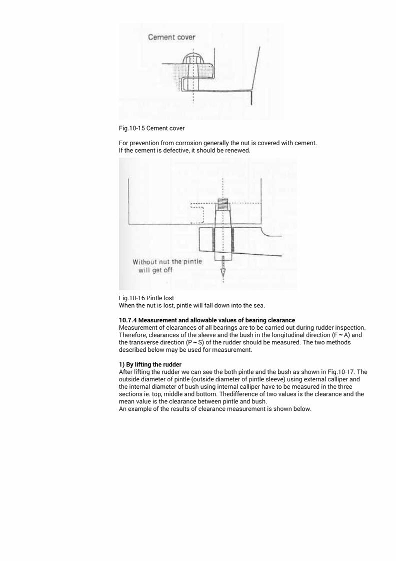
Fig.10-15 Cement cover
For prevention from corrosion generally the nut is covered with cement.If the cement is defective, it should be renewed.
Fig.10-16 Pintle lostWhen the nut is lost, pintle will fall down into the sea.
10.7.4 Measurement and allowable values of bearing clearance Measurement of clearances of all bearings are to be carried out during rudder inspection.Therefore, clearances of the sleeve and the bush in the longitudinal direction (F~A) andthe transverse direction (P~S) of the rudder should be measured. The two methodsdescribed below may be used for measurement.
1) By lifting the rudderAfter lifting the rudder we can see the both pintle and the bush as shown in Fig.10-17. Theoutside diameter of pintle (outside diameter of pintle sleeve) using external calliper andthe internal diameter of bush using internal calliper have to be measured in the threesections ie. top, middle and bottom. Thedifference of two values is the clearance and themean value is the clearance between pintle and bush. An example of the results of clearance measurement is shown below.
Fig.10-17 Measurement of pintle clearance
2) Without lifting the rudderWithout lifting the rudder,we can measure the clearance using a feeler gauge insertingbetween the bush and the sleeve. The method of measuring clearances using a feelergauge is shown in the Fig.10-19.The measurement is the same as above ie. fore-aft and P and S side.But in this case we can not measure the clearance at the middle section.
Fig.10-18 Feeler gaugeThe feeler gauge is a collection of thin metal plates of various thickness.
Measure from bottom Measure from top
Fig.10-19 Measuring pintle clearance
Clearances in the longitudinal (fore and aft) and transverse directions (P and S) should bemeasured in the similar way as before mentioned.2-1) False clearanceWhen measuring the pintle clearance using a feeler gauge, the measurement of clearanceat the end of the bush sometimes shows a smaller value while the actual value of theclearance is bigger. As shown in Fig. 10.20 and 21, the end of the bush should be chippedoff and the clearance should be measured accurately.
Fig.10-20 Fales clearance
Fig.10-21 Example of actual measurement
Left : New bush
Right : Weared bush,Only lower end is normal.
2-3) Standard Clearancei) PintleFor a newly built ship, the standard clearance is 1.5 mm.For a ship in service, Maximum allowable clearances between pintle and bush is 6 mm.IF the actual clearance exceeeds 6mm, the bush should be renewed.
3) Neck bearingClearance in the neck bearing can be measured after the rudder is overhauled. Unlessother wise the measurement is carried out using a feeler gauge.The standard clearance is4.0 mm, If the clearance exceeds 5.0mm, the bush should be replaced. Actually the weardown of the neck bearing bush is smaller than the pintle.
4) Examination of the Survey Report in previous surveyIf the clearance of the pintle is 5.5 mm, examine the past measurement results in thesurvey report. For instance, if the clearance at the previous inspection was 3.0 mm, theclearance increased by 2.5 mm. Then the clearance in the next survey will be increasedup to 8.0mm. so the renewal of the bush should be strongly recommended.If the clearance is 5.0 mm in the previous survey, In this case the wearingis only 0.5mm. renewal may be deferred until the next inspection. There are no clearly-defined standards for carrier-bearing clearances; however,examples of pastmeasurements of various bearings are given below. The "△" mark indicates that bushrenewal was recommended; The "A" mark indicates that renewal was deferred until thenext inspection.
Fig.10-23 Clearance of neck bearing
Fig.10-24 Clearance of carrier bearing
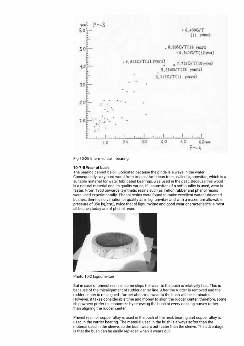
Fig.10-25 Intermediate bearing
10-7-5 Wear of bush The bearing cannot be oil lubricated because the pintle is always in the water.Consequently, very hard wood from tropical American trees, called lignumvitae, which is asuitable material for water lubricated bearings, was used in the past. Because this woodis a natural material and its quality varies; if lignumvitae of a soft quality is used, wear isfaster. From 1960 onwards, synthetic resins such as Teflon rubber and phenol resinswere used experimentally. Phenol resins were found to make excellent water lubricatedbushes; there is no variation of quality as in lignumvitae and with a maximum allowablepressure of 350 kg/cm2, twice that of lignumvitae and good wear characteristics, almostall bushes today are of phenol resin.
Photo.10-2 Lignumvitae
But in case of phenol resin, in some ships the wear to the bush is relatively fast. This isbecause of the misalignment of rudder center line. After the rudder is removed and therudder center is re- aligned , further abnormal wear to the bush will be eliminated.However, it takes considerable time and money to align the rudder center, therefore, someshipowners prefer to economize by renewing the bush at every docking survey ratherthan aligning the rudder center.
Phenol resin or copper alloy is used in the bush of the neck bearing and copper alloy isused in the carrier bearing. The material used in the bush is always softer than thematerial used in the sleeve, so the bush wears out faster than the sleeve. The advantageis that the bush can be easily replaced when it wears out.
10.7.6 Slack of sleeveThe cylindrical sleeve is expanded by heating, and when the inner diameter becomeslarge, the pintle is inserted by shrinkage-fitting. The twomembers are only held against each other physically; therefore, the sleeve might becomeslack due to vibrations or ingress of sea water between the members. If the slack isexcessive, the sleeve drops. When the rudder is lifted, strike the sleeve with a testhammer and check for slack. If we press the sleeve lightly with a finger while striking itwith a test hammer, we might feel a slack of sleeve. If we find some slack, strike allaround the sleeve with the hammer and record the slacked locations. If the slack is foundover 2/3 rd of all surface , the sleeve should be replaced.
Fig.10-00 False clearanceActual clearance (Left side) is much bigger than the value measured withfiller gauge.
Fig.10-00 Examination of actual measurement
Fig.10-00 Exaninination of sleeve sluck with test hammer,If the sleeve is sluck, the finger feels somthing like vacant.
Fig.10-00 Sketch showing sleeve sluckSlack is bigger in both P and S side
10-7-7 Corrosion of bush retainer or supportThe bush retainer and support are a comparatively thiner welded rings made of steelplate. If some part of this ring is corroded, bush might work loose and fall off. When theybecome excessively thin, the bush retainer or support should be replaced, If the bush hasbeen shrinkage-fitted into the shoe piece, it will not fall off; however, there are instancesof the bush disappered. The worn bush turned into a fine pieces, which in turn found itsway between the pintle and the shoe piece then disappeared.
Fig.10-31 Bush stopper
10-7-8 Corrosion of pintle The copper alloy sleeve is shrinkage-fitted on the bearing surface of the forged steelpintle, therefore, the ends of the sleeve are likely to be subjected to galvanic action.Sometimes the tapered end of the pintle corrodes circumferentially and its thickness isreduced only at the corroded part. Moreover, the tapered part of the pintle is in metalliccontact with the cast parts of the pintle. If the sea water enters into the small clearance,the tapered part corrodes; therefore, 0-rings are generally fitted at both ends of the sleeve.If 0-rings are not fitted, or no longer exist, the tapered part gradually corrodes due to theeffects of the sea water, and finally, the hair crack appears around the taper end of thepintle. Dering long years the crack increase and the pintle will broken.This defect cannot be detected unless the pintle is removed. There have been instanceswhere the pintle was removed because it had become loose, and it was found that thetapered part had corroded excessively.
If the sea water has enteres into this clearance between the sleeve and the pintle itself,the shrinkagr-fitted sleeve becomes slack because of pintle corrosion; if this situation isnot rectified for a long period, the sleeve will work loose and fall off. We have found initialcorrosion in the pintl occuring circumferentially in the tapered part and then after thehair-cracks will appeare at this location. the next stage is corrosion due to sleeve slack,followed by corrosion in the tapered part.
Fig.10-32 Corrosion of pintle (1)
(1) Pintle corrosion(2) Pintle corrosion and sleeve slack(3) Corroded bush support(4) Corroded bush (large clearance)
Fig.10-33 Corrosion of pimtle (2)
Fig.10-34 Corrosion of pintle (3)
10-7-9 Repairing corroded pintle An excessively corroded pintle should be replaced, but if the corrosion is not heavy, thepintle can be repaired by welding depending on the material.(1) Pintle materialIn principle, welding repairs should not be carried out on forged steel pintle. However, ifthe carbon content of forged steel is less than 0.23% , welding repairs may be carried out.Therefore, the carbon content should be confirmed before carrying out welding repairs; ifit is greater than 0.23%, welding repairs should not be carried out.
(2) Procedure for welding repairsFig. 10-33 is a flow chart for welding repairs for forged steel materials.At firstly, the carbon content is checked and if the carbon content is less than 0.23%, therust is de-scaled. Very small flaws are checked by ultrasonic testing. If cracks are found,they are chipped off. Next, the defective surface is welded all around. After heattreatment, the surface is machined up. After machining, a dye penetration test may becarried out as the final check.Then new sleeve after hydraulic test is shrinkage fitted.
Fig.10-33 Procedure for repairing of corroded pintle
Photo.10-3 Corroded pintle
10-8 Lifting and Lowering RudderThe rudder weight is supported at the top or the bottom.It is suspended from a thrust bearing in the rudder carrier in the steering gear room.However, in small ships, the rudder is supported with a heel disk below the rudder. If thethrust disk or the heel disk wears out, the rudder itself comes down. If the rudder comesdown excessively, its connection with the steering gear becomes defective; therefore, theclearance between the shoe piece and the rudder should be checked carefully during abottom inspection. Generally, the designd clearance between rudder bottom and shuepiece is 20 mm to 30 mm. If the clearance is between 0 and 10 mm, the heel diskshould be renewed, or the rudder carrier should be opened up and the surface of bearingdiskshould be examined.10-8-1 Wear to heel disk Generally two hard, semi-circular steel disk is fitted in the shoe piece and the bottom ofpintle, one above the other so that a point contact is obtained; however, the upper heeldisk is sometimes part of the pintle. In this case, the lower part of the pintle is semi-circular. This heel disk rotates together with the rudder and has a box-shaped spigot. Thesemi-circular shape of the heel disk becomes flat when it wears out, causing the ruddercomimg downwards. If the heel disk becomes thin due to wear, it should be renewed.
Fig.10-35 Support of rudder weight(left : Bottom support, right :top support (hangaing)
Fig.10-36 Clearance between rudder shoe piece
Fig.10-37 Heel disk
10-8-2 Thrust diskThe thrust disk is a copper alloy disk with etched oil grooves. Because the area of the
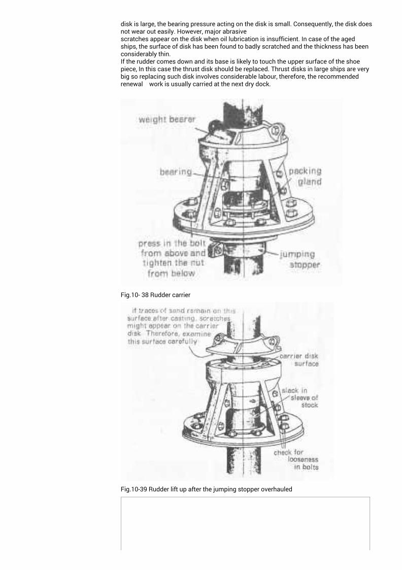
disk is large, the bearing pressure acting on the disk is small. Consequently, the disk doesnot wear out easily. However, major abrasivescratches appear on the disk when oil lubrication is insufficient. In case of the agedships, the surface of disk has been found to badly scratched and the thickness has beenconsiderably thin.If the rudder comes down and its base is likely to touch the upper surface of the shoepiece, In this case the thrust disk should be replaced. Thrust disks in large ships are verybig so replacing such disk involves considerable labour, therefore, the recommendedrenewal work is usually carried at the next dry dock.
Fig.10- 38 Rudder carrier
Fig.10-39 Rudder lift up after the jumping stopper overhauled
Photo.10-4 Scratched thrust disk
Photo.10-40 Combined thrust disk and bushThrust disk with integral bush is not recommended because when the disk is renewed thesound bush also renewed.
10-8-3 Jumping stopperIf the rudder is lifted when underway due to the wave impact or the contact with floatingobjects, and or bottom contact, the steering gear may be damaged. To prevent suchdamage, a jumping stopper is provided.The jumping stopper, as shown in Figure , may befitted over the gudgeon or assembled in the rudder carrier. the designed clearance is 2.0mm maximum.There are no instances of damage or corrosion to the jumping stopperitself. However, if the clearance measured is found to be large, it can beconcluded that the rudder has moved down. Because a hanging rudderdoes not have a shoe piece, one does not know whether the rudder hasmoved down or not; therefore, we recommend that you enter the rudder trunk andmeasure the clearance between the base of rudder carrier and the jumping stopper.
Fig.10-41Jumping stopper on the gudgeon
Fig.10-42 Jumping stopped under rudder carrier
Fig.10-43 Measuring of the clearance between junping stopper and the base of ruddercarrer in the rudder trunk
10-9 Rudder Corrosion 10-9-1 Corrosion of rudder plate In old ships, the rudder plate corrodes and its thickness decreases, similar to wear to theshell plate. However, the rate of wear of the rudder plate is gradual and is much smallerthan that of the shell plate; instances where the worn rudder plate has been cut out andreplaced after measurement with a thickness gauge are very rare. This is attributed to thelarge number of zinc anodes fitted for preventing corrosion of the rudder plate.If the worn rudder plate is cut out for replacement, or a large thick double plate has to beprovided. Unlike the hull structure, centring of the rudder is likely to be adversely affectedbecause of welding the deformation.Therefore, the rudder plate should be removed, placed on a level block, and welding workcarried out while the centring of the rudder is checked.
Fig.10-44 Centering of rudder (Fore - Aft and P -S side)
Fig.10-4 Fabrication of rudder
Photp.10-5 Centering of rudder on a level blockThe rudder plate is placed on a level block and measured the center line. LISNAVE Rocha,PORTUGAL
10.9.2 Corrosion due to erosion Irrespective of the age of ships, the upper, middle, and lower parts of the rudder plate andthe gudgeon in fine high-speed ships sometimes suffer from excessive spongi formcorrosion. This phenomenon is called erosion. The water flow generated by propellerrotation generates air bubbles in the flow at local locations where flow rate is high. Whenthese bubbles impinge on the rudder, they burst and disappear, but causemicroscopically large impacts on the rudder resulting in local corrosion of the rudderplate.
Fig.10-45 Erosion of rudder
If the surface is eroded, and there is continuous flow of water over this surface, corrosionadvances further. There are no fool-proof measures against corrosion; the rudder plate issometimes built up by welding, and forged parts such as the gudgeon are sometimescovered with cement or Devcon, but at the next drydocking, similar corrosion can also befound in the cement; therefore, effective repair methods have not yet been discovered.However, as corrosion is localised, the strength of the rudder is not affected significantly,provided there is no hole in the rudder through which water can enter; therefore, this formof corrosion should not be of much concern.
10-10 Twist in Rudder Stock Among the damages of rudder the most troublesome damage is twisting of the rudderstock. In furthermore, In most cases twisting is accompanied with by bend of the rudderstock. As mentioned in (9) of Section 8., When we watch the rudder just aft in the dry dock andthe rudder is found to have swung to any P or S side, then the rudder stock is likely tohave twisted. Because when the ship is in dry dock always the rudder is kept justmidship.Twisting is caused due to the external force to the rudder plate in case of grounding,touching with mud, rock or floating objects. Without knowing that the rudder is fixed,when the rudder is taken by force of steering gear the rudder stock will be twisted. Whilesailing , if the rudder suddenly responds strangely and becomes heavier than usual, therudder stock has probably twisted. However, if the angle of twist is small, there ispractically no effect on steering;When the twisting angle is less than two degrees, there is no problem.But when the ship heavily stranded, the twisting combined with bending of rudder stock.以下未校正
10-10-1 Position of twist Not the same as dents and cracks, It is very difficult to find the position of twist .The rudder stock above the neck bearing is slender, so the most cases it may beassumed that this part of the rudder stock will be twisted, But it is very difficult to check aposition correctly.The twisting angle is measured after the rudder stock is oberhauled and placed on thelevel block. The difference of the position of key way on the top of rudder stock and theposition of rudder flange. In this case only we recognize the twisting angle but we can notfind the position of twisted area becaus there is no reference longitudinal line on therudder stock.The rules of the Germanischer Lloyd ( the German classification society) prescribe thereplacement of the rudder stock when the angle of twist is greater than 10 degrees.
If the twist is 10 degrees, the case where the twist has occurred throughout the length ofthe rudder stock, say over a range of 3 m, is quite different from the case where the twisthas occurred in a range of 50 cm in the rudder stock; while the twist in the former is 0.3degrees per unit length, the twist in the latter is nearly six times this value. For instance,the report does not have an entry such as "twist was found over a distance of 1,500 mmfrom a point 2,000 mm above the coupling in the upward direction", because nobodyknows the range of twisting. One reason for this is that permissible values of twist havenot been decided. In the new building a reference line in the longitudinal direction shouldbe marked on the rudder stock.捩れの図面を作成し挿入
10-10-2 Actual examples of twist As mentioned above, GL requires replacement of rudder stock if the twist exceeds 10degrees, but we are inclined to think that this requirement has been simplified beyond ourreasoning. Results of damage and repairs of twisted rudded stock experienced duringsurvey are as follows ;
10-10-3 Repairing twistTwist occurs because of stranding and bottom contact, therefore, repair costs aregenerally covered by insurance. For this reason, there are many instances of renewingthe rudder stock. However, as the rudder stock is a large forged block, a considerabletime is required to procure materials. It is customary to carry out temporary repairs andrenew the rudder stock later.The following precautions should be taken during repairs:
1) The keyway was subject to large forces, therefore, confirm using ultrasonic testing thatcracks are not present.
2) The entire rudder stock is subjected to twisting forces, therefore, examine the entiresurface of the rudder stock for very small flaws.3) For details of welding the keyway, see 10-7-9(2) "Procedure for Welding Repairs"
Table 10-2 Example of repair works on the twisted rudder stock
(1) If the twist angle is comparatively small as shown in the figure, the keyway for therudder stock and the tiller is machined to increase its size so that a larger key can befitted.The method of retaining the original keyway and adjusting the position of the steeringgear may also be considered, but I have not heard of actual examples of such a practice.For the ship in. E on the Table 10-2, however, the quadrant was increased in size byadding an extra piece and the rudder angle was corrected; this is an example of adjustingthe steering gear.
Fig.10-46 Adjustment using a new bigger key
Fig.10-47 Adjustment of quadrant
(2) Big twist angleIf the twisted angle is so large that repairs to the key alone are inadequate, the keywaycan be built up by welding, the welded part checked for flaws by ultrasonic tests, and anew keyway cut to suit the twisted angle. The rudder stock can be used even though it istwisted. However, because of the twist, the rudder stock might have flaws that are notvisible to the eyes; therefore, it should be examined by non-destructive tests such asultrasonic flaw detection, magnetic particle test or dye penetrant test (colour check).If very small cracks are detected, depending on the sizes of the cracks, they may bechipped out or other measures adopted to eliminate them.This is a temporary repair method; after repairs are carried out , the shipowner has toprocure a new rudder stock and replaced. however, these repairs may be accepted aspermanent repairs.
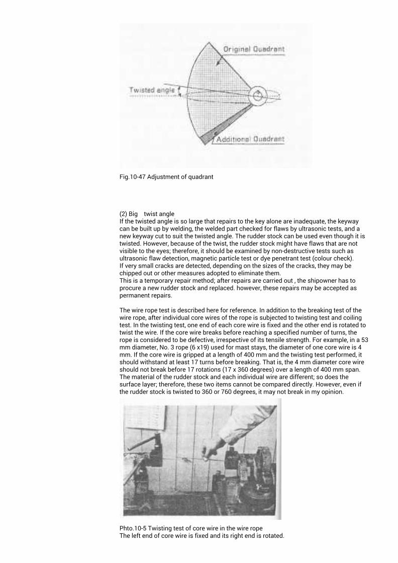
The wire rope test is described here for reference. In addition to the breaking test of thewire rope, after individual core wires of the rope is subjected to twisting test and coilingtest. In the twisting test, one end of each core wire is fixed and the other end is rotated totwist the wire. If the core wire breaks before reaching a specified number of turns, therope is considered to be defective, irrespective of its tensile strength. For example, in a 53mm diameter, No. 3 rope (6 x19) used for mast stays, the diameter of one core wire is 4mm. If the core wire is gripped at a length of 400 mm and the twisting test performed, itshould withstand at least 17 turns before breaking. That is, the 4 mm diameter core wireshould not break before 17 rotations (17 x 360 degrees) over a length of 400 mm span.The material of the rudder stock and each individual wire are different; so does thesurface layer; therefore, these two items cannot be compared directly. However, even ifthe rudder stock is twisted to 360 or 760 degrees, it may not break in my opinion.
Phto.10-5 Twisting test of core wire in the wire ropeThe left end of core wire is fixed and its right end is rotated.
the speed at which the wire is turned is also a factor to beconsidered: it should be 60 tuenes per minute.
Fig.10-48 Adustment of twistingThe old key way (shown in full line) is built up by welding; a new key way(in dotted line) is cut to suit the twist of the rudder stock (* theta) and thethe tiller position is adjusted to suit the rudder.10-11 Others10-11-1. Flap rudder In order to improve the response of the rudder.The flap is fitted behind the rudder plate.This rdder is called Becker rudder. The point of the inspection is as follows:The link mechanism and the connecting hinges including the flange are to be carefullyinspected . If necessary, wear in the bearing may be measured at an overhaul inspection.At Special Survey, in addition to above inspection, operation tests are to be carried out .
Fig.10-45 Flap rudder
10-11-2 Intermediate bearingThe rudder is generally supported at three points; In case o f a hanging rudder, thesupporting poinnt is two. However, in rare cases, some ships have rudders supported atfour points, with an additional intermediate bearing below the uppermost support, namelythe rudder carrier.
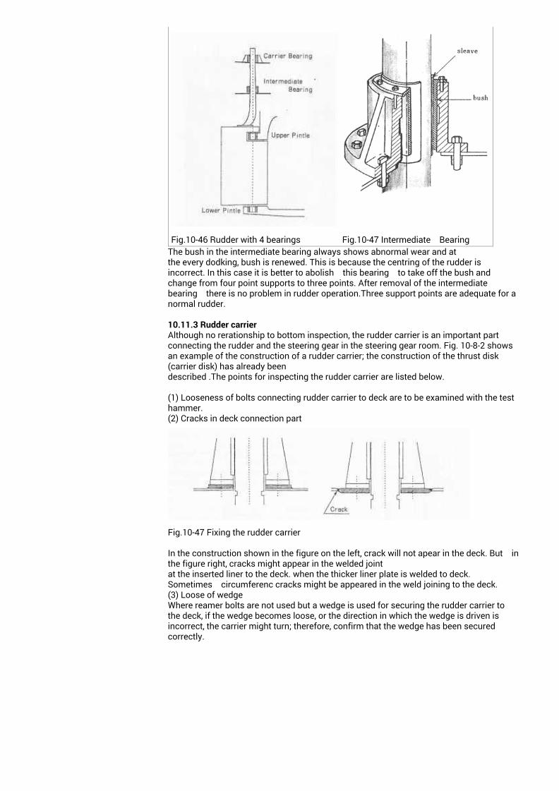
Fig.10-46 Rudder with 4 bearings Fig.10-47 Intermediate BearingThe bush in the intermediate bearing always shows abnormal wear and atthe every dodking, bush is renewed. This is because the centring of the rudder isincorrect. In this case it is better to abolish this bearing to take off the bush andchange from four point supports to three points. After removal of the intermediate bearing there is no problem in rudder operation.Three support points are adequate for anormal rudder.
10.11.3 Rudder carrier Although no rerationship to bottom inspection, the rudder carrier is an important partconnecting the rudder and the steering gear in the steering gear room. Fig. 10-8-2 showsan example of the construction of a rudder carrier; the construction of the thrust disk(carrier disk) has already beendescribed .The points for inspecting the rudder carrier are listed below.
(1) Looseness of bolts connecting rudder carrier to deck are to be examined with the testhammer.(2) Cracks in deck connection part
Fig.10-47 Fixing the rudder carrier
In the construction shown in the figure on the left, crack will not apear in the deck. But inthe figure right, cracks might appear in the welded jointat the inserted liner to the deck. when the thicker liner plate is welded to deck.Sometimes circumferenc cracks might be appeared in the weld joining to the deck.(3) Loose of wedgeWhere reamer bolts are not used but a wedge is used for securing the rudder carrier tothe deck, if the wedge becomes loose, or the direction in which the wedge is driven isincorrect, the carrier might turn; therefore, confirm that the wedge has been securedcorrectly.
Fig.10-48 Fixing the rudder carrier fixed with edge
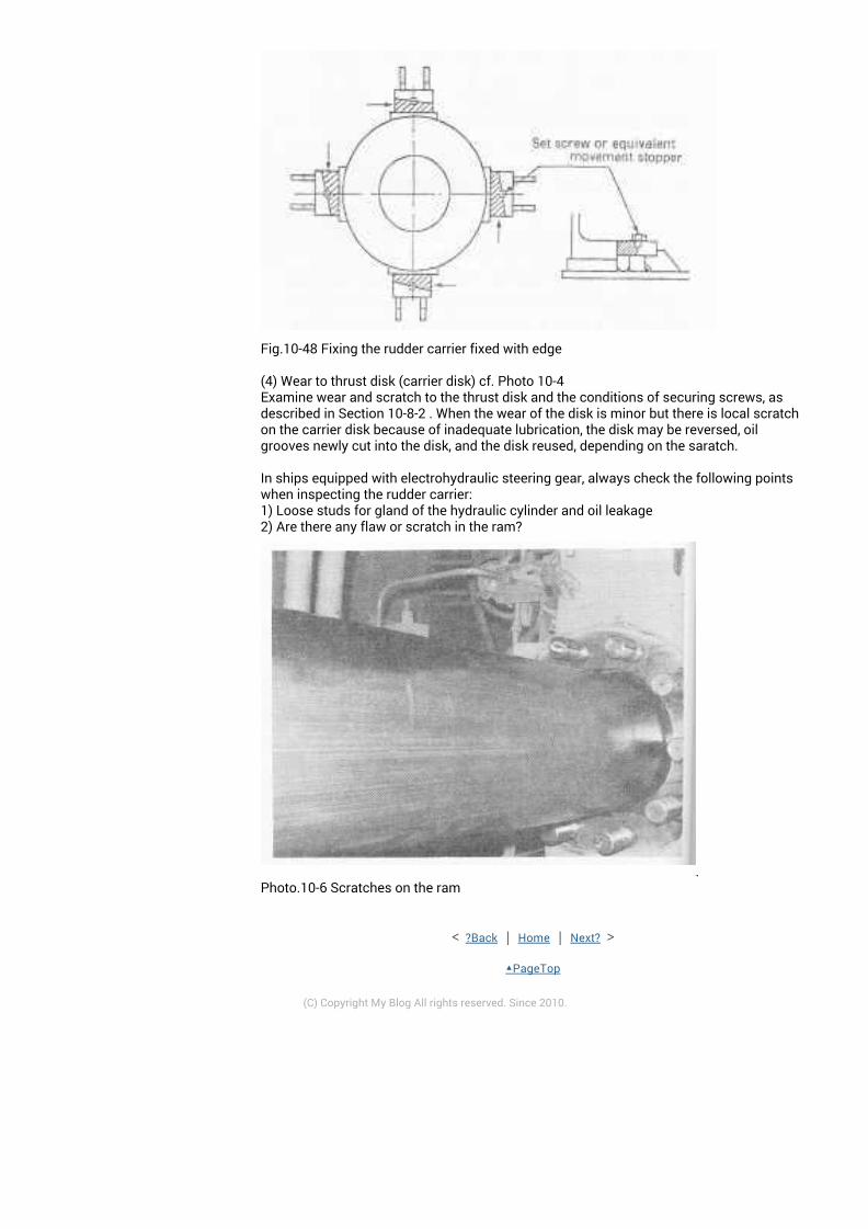
(4) Wear to thrust disk (carrier disk) cf. Photo 10-4Examine wear and scratch to the thrust disk and the conditions of securing screws, asdescribed in Section 10-8-2 . When the wear of the disk is minor but there is local scratchon the carrier disk because of inadequate lubrication, the disk may be reversed, oilgrooves newly cut into the disk, and the disk reused, depending on the saratch.
In ships equipped with electrohydraulic steering gear, always check the following pointswhen inspecting the rudder carrier:1) Loose studs for gland of the hydraulic cylinder and oil leakage2) Are there any flaw or scratch in the ram?
.Photo.10-6 Scratches on the ram
< ?Back | Home | Next? >
▲PageTop
(C) Copyright My Blog All rights reserved. Since 2010.