16
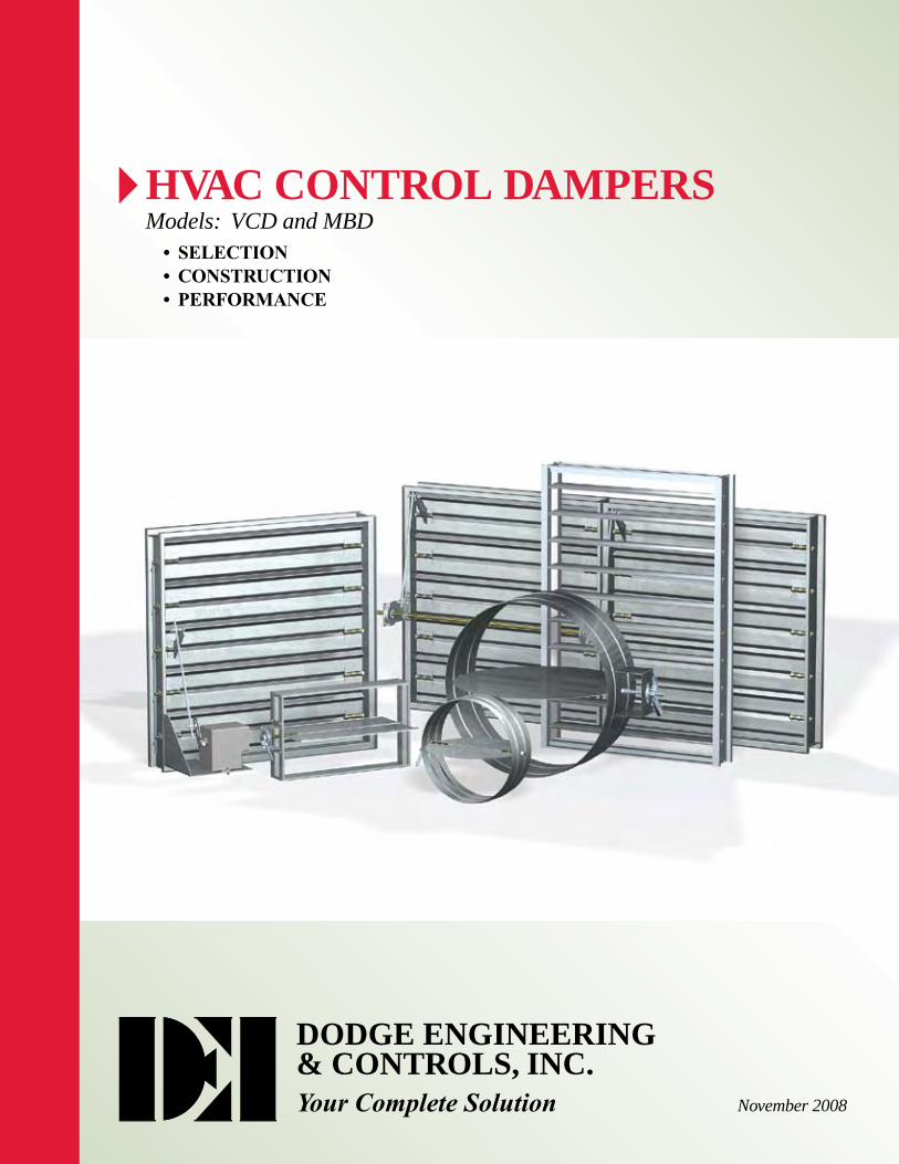
HVAC CONTROL DAMPERS Models: VCD and MBD • sElECTIon • ConsTruCTIon • pErFormanCE DODGE ENGINEERING & CONTROLS, INC. Your Complete Solution November 2008
2
June2008
hvAc control dAMpersModels: VCD and MBD
• sElECTIon• ConsTruCTIon• pErFormanCE
dodge engineering& controls, inc.YourCompleteSolution November 2008

2
Comprehensive state-of-the-art laboratory and testing facilities have always been important to the success of these product lines. Our vendor’s laboratory facility, which is devoted exclusively to development and testing of damper related�products,�contains�the�HVAC�industry’s�most�extensive�and�modern�equipment�for�testing�to�the�latest�versions�of�AMCA,�ANSI,�ASHRAE,�UL,�and�other�industry�standards�of�performance.�These�laboratory�capabilities�are�used�to provide the most comprehensive performance data, including leakage and pressure loss, over the widest range of sizes.�Their�lifecycle�and�endurance�testing�goes�far�beyond�any�current�industry�requirements.
HVACControlandManualBalancingDampers
Let Dodge Engineering & Controls provide dampers and damper�actuation�to�meet�your�project�needs.�Send�us�your�damper�schedule�for�a�quote�and� great pricing.
toll Free:� (877)�334-2875
Fax:� (978)�244-1422
Website: DEIControls.com
e-mail:� [email protected]
Mail:� 196�Riverneck�Road Chelmsford,�MA�01824
Our dampers are shipped directly to you from many convenient locations throughout the country to better serve you.
We also offer Fast Track service for even faster delivery.
• StrongSupport
• ProductsYouCanTrust

3
Axle
Bearing
Blade
Frame
Linkage
Jamb Seal
Blade Seal
ShaftExtensionManual Quadrant Kit
DriveArrangementDefinition
Damper Width
Dam
per H
eightActuator or
Manual Quadrant
Jackshaft
22-2FEL-2
Each damper is given a drive arrangement code that helps describe the construction of the damper. The following breaks down what each number and letter represents.
1 Number of sections wide
2 Number of sections high
3 Number of actuators or manual quadrants
4 Who supplies the actuators or manual quadrants F - Factory C - Customer Supplied (field mounted)
5 Actuator or manual quadrant mounting E - External I - Internal B - Both internal and external
6 Actuator or manual quadrant location L - Left-hand drive R - Right-hand drive B - Both right and left
7 Number of jackshafts
VCDModels
1 2 3 4 5 6 7
ConstructionFeatures

4
Part�of�our�unique�approach�to�damper�construction,�Variable�Symmetric�Blade�Design�(VSB)�uses�two�principles�to�increase�damper�performance.�First,�all�damper�blades�are�symmetric�about�their�axis.�Second,�any�combination�of�4,�5,�6,�and�7�in.�(102,�127,�152,�and�178mm)�blade�widths�are�used�in�a�single�damper.�These two features are standard construction, providing the following advantages:
•�� IncreasesMountingFlexibility�-�Symmetrical�blades�have�identical�operating�characteristics regardless of airflow direction. This allows a control damper to be mounted in either direction of flow, an advantage when installing with space constraints.
•�� IncreasesFreeArea - Traditional damper designs with a single blade width require�oversized�blade�stops,�limiting�free�area�when�the�blades�are�open� (Figure 1). Blade stop height is able to be reduced, which maximizes free area, and increases damper performance (Figure 2).
•� ReducesActuatorTorque - If an unsymmetrical blade closes against airflow, a�large�amount�of�torque�is�needed�because�the�air�distribution�is�unbalanced.�The�VSB�design�balances�airflow�on�each�side�of�a�symmetrical�blade,�reducing�the�torque�required�to�operate�the�damper.�The�use�of�symmetrical�blades�has�allowed�us�to�reduce�the�sizes�and�quantities�of�actuators�used�on�our�dampers�(Figure 3).
ActuatorTorque
ActuatorTorque
Airflow worksagainstactuator
Airflow worksagainstactuator
Airflowworks with
actuator
Unbalanced BladeRequires Higher Torque
Balanced Blade Requires Less Torque
Free AreaMaximum Reduced
Greenheckwith VSB with 6 in. blades
with 7 in. blades
unbalancedblade
VariableSymmetricBladeDesign(VSB)
Figure 3
Blades3V�blades�are�fabricated�from�a�single�thickness�of�16�ga.�(1.5mm)�galvanized�steel�incorporating�three�longitudinal�V-Type grooves running the full length of the blade to increase strength. This blade is standard on models VCD-15, 18,�20,�20V,�23,�23V,�and�SEVCD-23,�designed�for�low�to�medium�velocity�and�pressure�capabilities.
Airfoil blades are constructed of double skin galvanized steel or heavy gauge extruded aluminum. This blade design presents a lower resistance to airflow and strength that is typically used in high pressure systems. Airfoil blades are standard�on�models�VCD-33,�33V,�34,�40,�42,�42V,�43,�43V�and�SEVCD-33.
ParallelVersusOpposedBladeOperationControl dampers are offered with either parallel or opposed blades. Each style has distinguishing characteristics�in�regards�to�the�type�of�operation�required.
•� Parallelbladeoperation�-�This�configuration�requires�the�damper�blades�to�open�or�close�in�the same direction, parallel to one another. Parallel blade orientation is typically used when the damper operates in two positions, open or close.
•� Opposedbladeoperation - Adjacent damper blades will open or close opposite one another under opposed blade configuration. Opposed blade orientation is typically used on dampers that modulate airflow.
LinkageTraditional damper linkages are found in the airstream, adding to the pressure drop of the damper blades and frame. Control dampers have blade linkage concealed in the frame to prevent additional pressure drop. With standard plated steel construction (stainless steel optional), linkage is engineered to accurately control each and every blade without need for adjustment.
ParallelBlades
OpposedBlades
FreeArea
FreeArea
Figure 1 Figure 2
3V Blade Steel Airfoil Blade Aluminum Airfoil Blade
DesignandConstructionFeatures
5
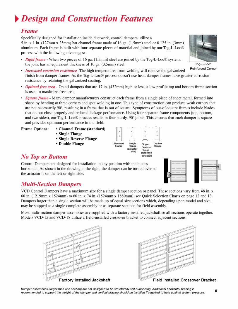
FrameSpecifically�designed�for�installation�inside�ductwork,�control�dampers�utilize�a 5�in.�x�1�in.�(127mm�x�25mm)�hat�channel�frame�made�of�16�ga.�(1.5mm)�steel�or�0.125�in.�(3mm)�aluminum. Each frame is built with four separate pieces of material and joined by our Tog-L-Loc® process with the following advantages:
•� �Rigidframe�-�When�two�pieces�of�16�ga.�(1.5mm)�steel�are�joined�by�the�Tog-L-Loc®�system,�the�joint�has�an�equivalent�thickness�of�10�ga.�(3.5mm)�steel.
•� Increasedcorrosionresistance -The high temperatures from welding will remove the galvanized finish from damper frames. As the Tog-L-Loc® process doesn’t use heat, damper frames have greater corrosion resistance by retaining the galvanized coating.
•� Optimalfreearea�-�On�all�dampers�that�are�17�in.�(432mm)�high�or�less,�a�low�profile�top�and�bottom�frame�section�is used to maximize free area.
•� Squareframe�-�Many�damper�manufacturers�construct�each�frame�from�a�single�piece�of�sheet�metal,�formed�into�shape by bending at three corners and spot welding in one. This type of construction can produce weak corners that are�not�necessarily�90º,�resulting�in�a�frame�that�is�out�of�square.�Symptoms�of�out-of-square�frames�include�blades�that do not close properly and reduced leakage performance. Using four separate frame components (top, bottom, and�two�sides),�our�Tog-L-Loc®�process�results�in�four�sturdy,�90º�joints.�This�ensures�that�each�damper�is�square�and provides optimum performance in the field.
Frame options: • Channel Frame (standard) • single Flange • single reverse Flange • Double Flange
NoToporBottomControl Dampers are designed for installation in any position with the blades horizontal. As shown in the drawing at the right, the damper can be turned over so the actuator is on the left or right side.
Damper assemblies (larger than one section) are not designed to be structurally self-supporting. Additional horizontal bracing is recommended to support the weight of the damper and vertical bracing should be installed if required to hold against system pressure.
Multi-SectionDampersVCD�Control�Dampers�have�a�maximum�size�for�a�single�damper�section�or�panel.�These�sections�vary�from�48�in.�x�60�in.�(1219mm�x�1524mm)�to�60�in.�x�74�in.�(1524mm�x�1880mm),�see�Quick�Selection�Charts�on�page�12�and�13.�Dampers�larger�than�a�single�section�will�be�made�up�of�equal�size�sections�which,�depending�upon�model�and�size,�may be shipped as a single complete assembly or as separate sections for field assembly.
Most�multi-section�damper�assemblies�are�supplied�with�a�factory�installed�jackshaft�so�all�sections�operate�together.�Models�VCD-15�and�VCD-18�utilize�a�field-installed�crossover�bracket�to�connect�adjacent�sections.
Factory Installed Jackshaft Field Installed Crossover Bracket
StandardFrame
DoubleFlange
SingleFlange
SingleReverse Flange(actuator
side) (oppositeactuator)
Tog-L-Loc®
Reinforced Corner
DesignandConstructionFeatures
6
FBH
FW
BW
BHFH
FW
FH
BW
FBV
BH BH
BW
FH FW
FBR
TransitionsIn�applications�where�dampers�require�installation�in�round�or�oval�openings, our control dampers can be supplied with the appropriate transition option. Rectangular dampers are constructed 1 inch (25mm), or 2 inches (51mm) larger than the dimensions provided and installed in a factory sleeve. The sleeve is transitioned at each end to the appropriate round, oval, or rectangular size. Transition options available
Type O Type R Type C
OnePieceRetainingAnglesA one piece retaining angle, the POC (literally named for being a “Piece of Cake”) makes control damper installation a breeze. The POC angle is designed by fastening four pieces together to form one piece. When installed the angle simply wraps around the sleeve of the damper and fastened in place.
ADamperLocation
L
CL Damper Frame
Sleeve
Damper D*
D* + 2 in. sq.
FactorySleeveOptionControl dampers are available in factory furnished sleeves in lengths up to 48�in.�(1219mm).�Sleeves�are�constructed�out�of�10�through�20�ga.�(3.25�through 0.91 mm) galvanized steel. When dampers are installed in ductwork, the “A” dimension specifies location of damper within the sleeve.
SecurityBarsWhen security becomes an issue, use our optional factory installed security bars. Security�bars�are�factory�welded�into�a�10�ga.�(3.5mm)�sleeve.�
Damper/LouverinaCommonSleeveA�common�sleeve�can�be�provided�for�your�applications�requiring�single�unit assembly. This assembly makes it convenient for installing in the field as one unit instead of dealing with multiple units (consult factory for more information).
UNIT/SLEEVE DEPTH
LOUVERDAMPER/
ACTUATOR
Face&BypassDampersMost�VCD�models�can�be�supplied�in�a�Face�& Bypass configuration where the sections of the damper operate opposite from each other. Face & Bypass dampers are available in vertical, horizontal, and right angle arrangements as shown at the right.
OptionsandAccessories
7
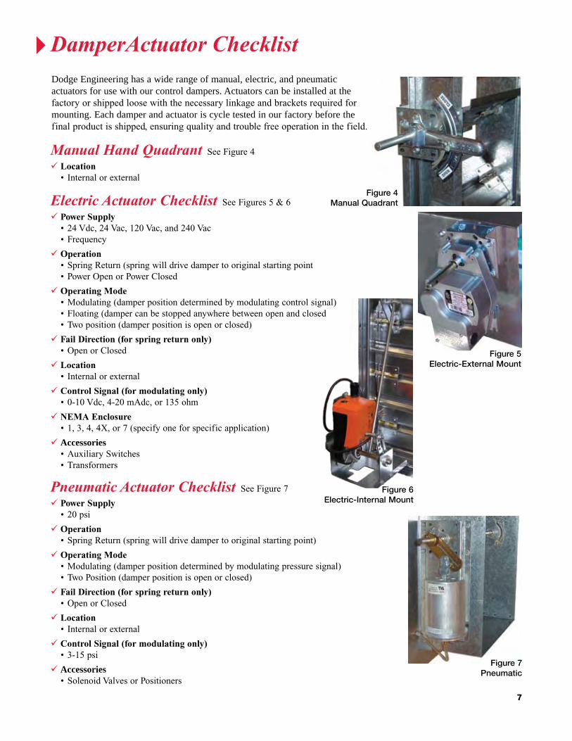
Figure 7Pneumatic
PneumaticActuatorChecklist��See�Figure�7 power supply •�20�psi
operation •�Spring�Return�(spring�will�drive�damper�to�original�starting�point)
operating mode •�Modulating�(damper�position�determined�by�modulating�pressure�signal) •�Two�Position�(damper�position�is�open�or�closed)
Fail Direction (for spring return only) •�Open�or�Closed
location •� Internal�or�external
Control signal (for modulating only) •�3-15�psi
Accessories •�Solenoid�Valves�or�Positioners
Figure 4Manual Quadrant
ManualHandQuadrant��See�Figure�4 location •� Internal�or�external
ElectricActuatorChecklist��See�Figures�5�&�6 power supply •�24�Vdc,�24�Vac,�120�Vac,�and�240�Vac •�Frequency
operation •�Spring�Return�(spring�will�drive�damper�to�original�starting�point •�Power�Open�or�Power�Closed
operating mode •� �Modulating�(damper�position�determined�by�modulating�control�signal)
� •�Floating�(damper�can�be�stopped�anywhere�between�open�and�closed •�Two�position�(damper�position�is�open�or�closed)
Fail Direction (for spring return only) •�Open�or�Closed
location •� Internal�or�external
Control signal (for modulating only) •�0-10�Vdc,�4-20�mAdc,�or�135�ohm
nEma Enclosure •�1,�3,�4,�4X,�or�7�(specify�one�for�specific�application)
Accessories •�Auxiliary�Switches •�Transformers
Figure 5Electric-External Mount
Figure 6Electric-Internal Mount
Dodge Engineering has a wide range of manual, electric, and pneumatic actuators for use with our control dampers. Actuators can be installed at the factory�or�shipped�loose�with�the�necessary�linkage�and�brackets�required�for�mounting. Each damper and actuator is cycle tested in our factory before the final�product�is�shipped,�ensuring�quality�and�trouble�free�operation�in�the�field.
DamperActuatorChecklist
8
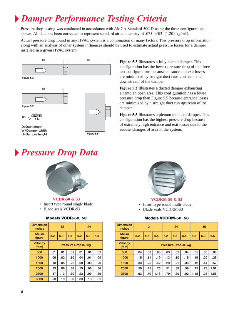
5D 6D
Figure 5.3
Figure 5.2
5D
Figure 5.5
4 (W) (H)D=3.14
D=Duct lengthW=Damper widthH=Damper height
Figure 5.3 Illustrates a fully ducted damper. This configuration has the lowest pressure drop of the three test configurations because entrance and exit losses are minimized by straight duct runs upstream and downstream of the damper.
Figure 5.2 Illustrates a ducted damper exhausting air into an open area. This configuration has a lower pressure drop than Figure 5.5 because entrance losses are minimized by a straight duct run upstream of the damper.
Figure 5.5 Illustrates a plenum mounted damper. This configuration has the highest pressure drop because of extremely high entrance and exit losses due to the sudden changes of area in the system.
Pressure�drop�testing�was�conducted�in�accordance�with�AMCA�Standard�500-D�using�the�three�configurations�shown.�All�data�has�been�corrected�to�represent�standard�air�at�a�density�of�.075�lb/ft3��(1.201�kg/m3).
Actual pressure drop found in any HVAC system is a combination of many factors. This pressure drop information along with an analysis of other system influences should be used to estimate actual pressure losses for a damper installed in a given HVAC system.
5D 6D
Figure 5.3
Figure 5.2
5D
Figure 5.5
4 (W) (H)D=3.14
Dimensioninches
12 24
AMCA figure
5.2 5.3 5.5 5.2 5.3 5.5
Velocity (fpm)
Pressure Drop in. wg
500 .01 .01 .02 .01 .01 .02
1000 .06 .02 .10 .04 .01 .09
1500 .13 .05 .22 .08 .03 .20
2000 .23 .08 .38 .15 .06 .36
2500 .37 .13 .60 .23 .09 .56
3000 .53 .19 .86 .33 .13 .81
Models VCDR-50, 53
Dimensioninches
12 24 36
AMCA figure
5.2 5.3 5.5 5.2 5.3 5.5 5.2 5.3 5.5
Velocity (fpm)
Pressure Drop in. wg
500 .04 .03 .05 .03 .02 .04 .05 .05 .06
1000 .15 .11 .19 .13 .10 .15 .19 .20 .25
1500 .33 .25 .42 .29 .21 .33 .42 .44 .57
2000 .59 .45 .75 .51 .38 .59 .75 .79 1.01
2500 .93 .70 1.18 .79 .60 .92 1.18 1.23 1.58
Models VCDRM-50, 53
vcdr-50 & 53•�� Insert�type�round�single�blade•�� Blade�seals�VCDR-53
vcdrM-50 & 53•�� Insert�type�round�multi-blade•�� Blade�seals�VCDRM-53
DamperPerformanceTestingCriteria
PressureDropData
9
Dimensioninches
12x12 24x24 36x36 12x48 48x12
AMCA figure
5.2 5.3 5.5 5.2 5.3 5.5 5.2 5.3 5.5 5.2 5.3 5.5 5.2 5.3 5.5
Velocity (fpm)
Pressure Drop in. wg
500 .04 .02 .06 .02 .01 .03 .01 .01 .03 .03 .02 .04 .01 .01 .03
1000 .14 .09 .22 .07 .04 .14 .04 .03 .12 .10 .07 .17 .06 .04 .13
1500 .31 .20 .50 .16 .09 .31 .09 .06 .26 .23 .16 .38 .13 .10 .30
2000 .55 .36 .89 .29 .16 .54 .16 .11 .46 .41 .29 .67 .23 .17 .53
2500 .86 .56 1.39 .45 .25 .85 .25 .17 .73 .63 .45 1.04 .36 .27 .83
3000 1.24 .81 2.00 .65 .35 1.22 .36 .29 1.05 .91 .64 1.50 .52 .39 1.19
3500 1.69 1.10 2.72 .89 .48 1.66 .49 .33 1.42 1.24 .88 2.05 .70 .53 1.62
4000 2.20 1.44 3.55 1.16 .63 2.17 .64 .42 1.86 1.62 1.14 2.67 .92 .70 2.11
Models VCD-20V, 23V
Dimensioninches
12x12 24x24 36x36 12x48 48x12
AMCA figure
5.2 5.3 5.5 5.2 5.3 5.5 5.2 5.3 5.5 5.2 5.3 5.5 5.2 5.3 5.5
Velocity (fpm)
Pressure Drop in. wg
500 .03 .01 .04 .01 .01 .03 .01 .01 .03 .01 .01 .03 .02 .01 .03
1000 .12 .06 .18 .06 .02 .13 .06 .02 .12 .05 .02 .12 .08 .04 .14
1500 .26 .13 .42 .12 .06 .29 .12 .05 .27 .12 .06 .27 .18 .10 .32
2000 .46 .23 .75 .22 .10 .52 .22 .09 .48 .21 .10 .49 .33 .18 .57
2500 .72 .37 1.17 .34 .16 .81 .34 .14 .75 .33 .16 .77 .51 .29 .89
3000 1.04 .53 1.68 .49 .23 1.17 .49 .21 1.08 .48 .24 1.11 .74 .42 1.28
3500 1.41 .73 2.29 .67 .32 1.60 .67 .29 1.48 .65 .33 1.51 1.0 .57 1.75
4000 1.84 .95 2.09 .87 .42 2.14 .88 .38 1.93 .85 .43 1.97 1.31 .74 2.29
Models VCD-33, 34, & SEVCD-33
Dimensioninches
12x12 24x24 36x36 12x48 48x12
AMCA figure
5.2 5.3 5.5 5.2 5.3 5.5 5.2 5.3 5.5 5.2 5.3 5.5 5.2 5.3 5.5
Velocity (fpm)
Pressure Drop in. wg
500 .04 .02 .06 .02 .01 .03 .01 .01 .03 .01 .01 .03 .03 .02 .04
1000 .14 .09 .22 .07 .04 .14 .04 .03 .12 .06 .04 .13 .10 .07 .17
1500 .31 .20 .50 .16 .09 .31 .09 .06 .26 .13 .10 .30 .23 .16 .38
2000 .55 .36 .89 .29 .16 .54 .16 .11 .46 .23 .17 .53 .41 .29 .67
2500 .86 .56 1.39 .45 .25 .85 .25 .17 .73 .36 .27 .83 .63 .45 1.04
3000 1.24 .81 2.00 .65 .35 1.22 .36 .24 1.05 .52 .39 1.19 .91 .64 1.50
3500 1.69 1.10 2.72 .89 .48 1.66 .49 .33 1.42 .70 .53 1.62 1.24 .88 2.05
4000 2.20 1.44 3.55 1.16 .63 2.17 .64 .42 1.86 .92 .70 2.11 1.62 1.14 2.67
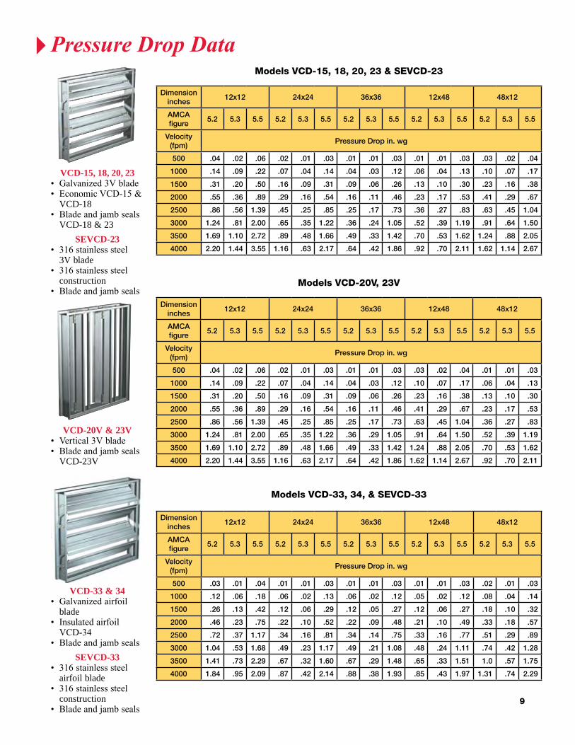
Models VCD-15, 18, 20, 23 & SEVCD-23
vcd-15, 18, 20, 23•� Galvanized�3V�blade•� �Economic�VCD-15�&�
VCD-18•� �Blade�and�jamb�seals�
VCD-18 & 23
sevcd-23•���316�stainless�steel�
3V blade•���316�stainless�steel�
construction •��Blade�and�jamb�seals
vcd-20v & 23v•� Vertical�3V�blade•��Blade�and�jamb�seals�
VCD-23V
vcd-33 & 34•� �Galvanized�airfoil�
blade•� �Insulated�airfoil�VCD-34•� Blade�and�jamb�seals
sevcd-33•� �316�stainless�steel�
airfoil blade•� �316�stainless�steel�
construction•� Blade�and�jamb�seals
PressureDropData

10
Dimensioninches
12x12 24x24 36x36 12x48 48x12
AMCA figure
5.2 5.3 5.5 5.2 5.3 5.5 5.2 5.3 5.5 5.2 5.3 5.5 5.2 5.3 5.5
Velocity (fpm)
Pressure Drop in. wg
500 .03 .01 .04 .01 .01 .03 .01 .01 .03 .02 .01 .03 .01 .01 .03
1000 .12 .06 .18 .06 .02 .13 .06 .02 .12 .08 .04 .14 .05 .02 .12
1500 .26 .13 .42 .12 .06 .29 .12 .05 .27 .18 .10 .32 .12 .06 .27
2000 .46 .23 .75 .22 .10 .52 .22 .09 .48 .33 .18 .57 .21 .10 .49
2500 .72 .37 1.17 .34 .16 .81 .34 .14 .75 .51 .29 .89 .74 .16 .77
3000 1.04 .52 1.68 .49 .23 1.17 .49 .21 1.08 .74 .42 1.28 .48 .24 1.11
3500 1.41 .73 2.29 .67 .32 1.60 .67 .29 1.48 1.0 .57 1.75 .65 .33 1.51
4000 1.84 .95 2.09 .87 .42 2.14 .88 .38 1.93 1.31 .74 2.29 .85 .43 1.97
Model VCD-33V
Dimensioninches
12x12 24x24 36x36 12x48 48x12
AMCA figure
5.2 5.3 5.5 5.2 5.3 5.5 5.2 5.3 5.5 5.2 5.3 5.5 5.2 5.3 5.5
Velocity (fpm)
Pressure Drop in. wg
500 .05 .03 .07 .01 .01 .04 .01 .01 .02 .01 .01 .03 .03 .02 .05
1000 .18 .12 .28 .05 .03 .17 .04 .02 .12 .01 .04 .18 .11 .06 .19
1500 .43 .28 .62 .12 .06 .37 .09 .05 .28 .14 .09 .40 .25 .14 .44
2000 .76 .49 1.11 .22 .11 .66 .17 .08 .50 .25 .16 .72 .44 .25 .78
2500 1.19 .77 1.73 .34 .17 1.04 .26 .13 .78 .39 .25 1.12 .69 .39 1.21
3000 1.71 1.11 2.50 .49 .24 1.50 .38 .19 1.13 .57 .36 1.62 1.0 .57 1.75
3500 2.33 1.51 3.41 .66 .33 2.04 .51 .26 1.53 .77 .49 2.21 1.36 .77 2.38
4000 3.04 1.98 4.45 .87 .43 2.66 .67 .34 2.01 1.01 .64 2.88 1.78 1.01 3.11
Models VCD-40, 42, 43
Dimensioninches
12x12 24x24 36x36 12x48 48x12
AMCA figure
5.2 5.3 5.5 5.2 5.3 5.5 5.2 5.3 5.5 5.2 5.3 5.5 5.2 5.3 5.5
Velocity (fpm)
Pressure Drop in. wg
500 .05 .03 .07 .01 .01 .04 .01 .01 .02 .03 .02 .05 .01 .01 .03
1000 .18 .12 .28 .05 .03 .17 .04 .02 .12 .11 .06 .19 .01 .04 .18
1500 .43 .28 .62 .12 .06 .37 .09 .05 .28 .25 .14 .44 .14 .09 .40
2000 .76 .49 1.11 .22 .11 .66 .17 .08 .50 .44 .25 .78 .25 .16 .72
2500 1.19 .77 1.73 .34 .17 1.04 .26 .13 .78 .69 .39 1.21 .39 .25 1.12
3000 1.71 1.11 2.50 .49 .24 1.50 .38 .19 1.13 1.0 .57 1.75 .57 .36 1.62
3500 2.33 1.51 3.41 .66 .33 2.04 .51 .26 1.53 1.36 .77 2.38 .77 .49 2.21
4000 3.04 1.98 4.45 .87 .43 2.66 .67 .34 2.01 1.78 1.01 3.11 1.04 .64 2.88
Models VCD-42V, 43V
vcd-40•� �Extruded�aluminum�
airfoil blade•� �Blades�contained�
within the frame•� Blade�and�jamb�seals
vcd-42 & 43•� �Extruded�aluminum�
airfoil blade•� �Galvanized�frame�-� VCD-42
•� �Aluminum�frame�-� VCD-43�
•� Blade�and�jamb�seals
vcd-33v•� ��Vertical�galvanized�
airfoil blade•� ��Blade�and�jamb�seals�
vcd-42v, 43v•� ��Vertical�extruded�
aluminum airfoil blade
•� ��Blade�and�jamb�seals�
PressureDropData
11
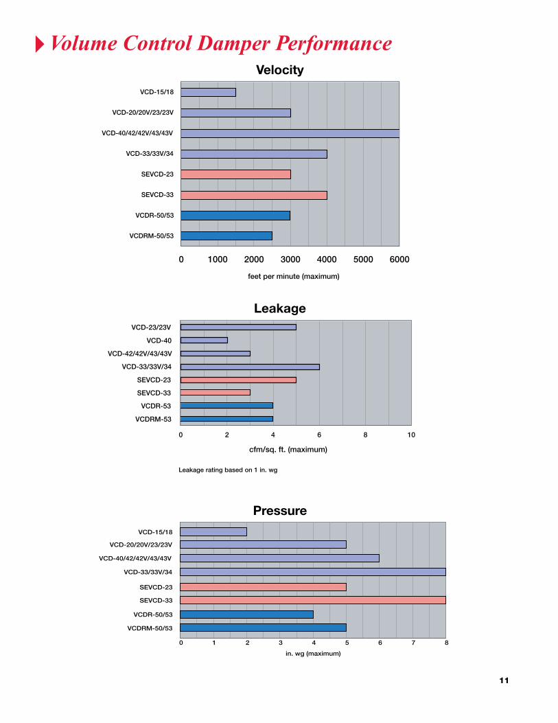
Pressure
0 1 2 3 4 5 6 7 8
VCD-15/18
VCD-20/20V/23/23V
VCD-40/42/42V/43/43V
VCD-33/33V/34
SEVCD-23
SEVCD-33
VCDR-50/53
VCDRM-50/53
in. wg (maximum)
Leakage
0 2 4 6 8 10
VCD-23/23V
VCD-40
VCD-42/42V/43/43V
VCD-33/33V/34
SEVCD-23
SEVCD-33
VCDR-53
VCDRM-53
cfm/sq. ft. (maximum)
Leakage rating based on 1 in. wg
Velocity
0 1000 2000 3000 4000 5000 6000
VCD-15/18
VCD-20/20V/23/23V
VCD-40/42/42V/43/43V
VCD-33/33V/34
SEVCD-23
SEVCD-33
VCDR-50/53
VCDRM-50/53
feet per minute (maximum)
Velocity
Leakage
Pressure
VolumeControlDamperPerformance
12
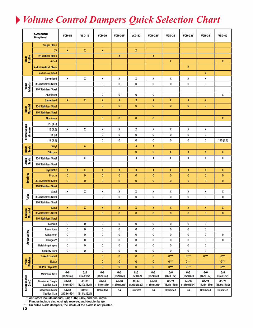
X=standardO=optional VCD-15 VCD-18 VCD-20 VCD-20V VCD-23 VCD-23V VCD-33 VCD-33V VCD-34 VCD-40
Blad
e Pr
ofile
Single Blade
3V X X X X
3V-Vertical Blade X X
Airfoil X X
Airfoil-Vertical Blade X
Airfoil-Insulated X
Fram
e M
ater
ial
Galvanized X X X X X X X X X
304 Stainless Steel O O O O O O O
316 Stainless Steel
Aluminum O O O O X
Blad
eM
ater
ial
Galvanized X X X X X X X X X
304 Stainless Steel O O O O O O O
316 Stainless Steel
Aluminum O O O O X
Fram
e Ga
uge
(in m
m)
20 (1.0)
16 (1.5) X X X X X X X X X
14 (2) O O O O O O O
12 (2.8) O O O O O O O .125 (3.2)
Blad
eSe
als Vinyl X X X
Silicone O O X X X X
Jam
bSe
als 304 Stainless Steel X X X X X X X
316 Stainless Steel
Bear
ings
Synthetic X X X X X X X X X X
Bronze O O O O O O O O O O
304 Stainless Steel O O O O O O O O O O
316 Stainless Steel
Axle
s
Steel X X X X X X X X X X
304 Stainless Steel O O O O O O O O
316 Stainless Steel
Link
age
Mat
eria
l Steel X X X X X X X X X X
304 Stainless Steel O O O O O O O O
316 Stainless Steel
Acce
ssor
ies
Sleeves O O O O O O O O O
Transitions O O O O O O O O O
Actuators* O O O O O O O O O O
Flanges** O O O O O O O O O O
Retaining Angles O O O O O O O O O
Security Bars O O O O O O O O O
Pain
tFi
nish
es
Baked Enamel O O O O O*** O*** O*** O***
Epoxy O O O O O*** O*** O***
Hi Pro Polyester O O O O O*** O*** O***
Sizi
ng in
ches
(mm
)
Minimum Size6x6
(152x152)6x6
(152x152)6x6
(152x152)6x6
(152x152)6x6
(152x152)6x6
(152x152)6x6
(152x152)6x6
(152x152)6x6
(152x152)6x6
(152x152)
Maximum Single Section Size
48x60(1219x1524)
48x60(1219x1524)
48x74(1219x1880)
74x48(1880x1219)
48x74(1219x1880)
74x48(1880x1219)
60x74(1524x1880)
74x60(1880x1524)
60x74(1524x1880)
60x74(1524x1880)
Maximum MultiSection Size
84x60(2134x1524)
84x60(2134x1524)
Unlimited NA Unlimited NA Unlimited NA Unlimited Unlimited
* Actuators include manual, 24V, 120V, 240V, and pneumatic. ** Flanges include single, single reverse, and double flange. *** On airfoil blade dampers, the inside of the blade is not painted.
VolumeControlDampersQuickSelectionChart

13
X=standardO=optional VCD-42 VCD-42V VCD-43 VCD-43V SEVCD-23 SEVCD-33 VCDR-50 VCDR-53 VCDRM-50 VCDRM-53
Blad
e Pr
ofile
Single Blade X X
3V X X X
3V-Vertical Blade
Airfoil X X X
Airfoil-Vertical Blade X X
Airfoil-Insulated
Fram
e M
ater
ial
Galvanized X X X X X X
304 Stainless Steel O O O O
316 Stainless Steel X X
Aluminum X X
Blad
eM
ater
ial
Galvanized X X X X
304 Stainless Steel O O O O
316 Stainless Steel X X
Aluminum X X X X
Fram
e Ga
uge
(in m
m)
20 (1.0) X X
16 (1.5) X X X X
14 (2) O O X X
12 (2.8) O O .125 (3.2) .125 (3.2) .125 (3.2) .125 (3.2)
Blad
eSe
als Vinyl X X
Silicone X X X X O X X
Jam
bSe
als 304 Stainless Steel X X X X X
316 Stainless Steel X X
Bear
ings
Synthetic X X X X
Bronze O O O O X X
304 Stainless Steel O O O O X X O O
316 Stainless Steel X X
Axle
s
Steel X X X X X X X X
304 Stainless Steel O O O O O O O O
316 Stainless Steel X X
Link
age
Mat
eria
l Steel X X X X X X
304 Stainless Steel O O O O O O
316 Stainless Steel X X
Acce
ssor
ies
Sleeves O O O O
Transitions O O O O
Actuators* O O O O O O O O O O
Flanges** O O O O O O
Retaining Angles O O O O
Security Bars O O O O
Pain
tFi
nish
es
Baked Enamel O*** O*** O*** O*** O O
Epoxy O*** O*** O*** O*** O O
Hi Pro Polyester O*** O*** O*** O*** O O
Sizi
ng in
ches
(mm
)
Minimum Size6x6
(152x152)6x6
(152x152)6x6
(152x152)6x6
(152x152)6x6
(152x152)6x6
(152x152)5
(127)5
(127)10
(254)10
(254)
Maximum Single Section Size
60x74(1524x1880)
74x60(1880x1524)
60x74(1524x1880)
74x60(1880x1524)
48x74(1219x1880)
60x74(1524x1880)
24(610)
24(610)
36(914)
36(914)
Maximum MultiSection Size
Unlimited NA Unlimited NA Unlimited Unlimited NA NA NA NA
* Actuators include manual, 24V, 120V, 240V, and pneumatic. ** Flanges include single, single reverse, and double flange. *** On airfoil blade dampers, the inside of the blade is not painted.
VolumeControlDampersQuickSelectionChart

14
Pressure
0 1 2 3 4 5 6 7 8
MBD-15
MBD-10/10MMBDR-50
in. wg (maximum)
Velocity
0 1000 2000 3000 4000 5000 6000
MBD-10/10M/15
MBDR-50
feet per minute (maximum)
Manual�balancing�dampers�are�designed�to�regulate�flow�of�air�in�a�HVAC�system.�Manual�balancing�dampers�are�not�intended to be used in applications for positive shut off or for automatic control.
* shown with optional standoff bracket
MBd-15•��Multi-blade•�� �Meets�SMACNA�recommended construction�requirements�
MBdr-50•� Round�Blade
MBd-10•� Single�Blade
X=standardO=optional
Blade Profile
MaterialFrame Gauge
(in mm)Bearings Axles
Linkage Material
Actuator Sizing inches (mm)
Single Blade
3V Galvanized20
(1.0)18
(1.3)16
(1.5)Synthetic Bronze Steel Steel
Manual Quadrant
1 1/2 in. Standoff Bracket
Minimum Size
Maximum Single Section
Size
Maximum Multi-section
Size
MBD-10 X X X X O6 x 4
(152 x 102)36 x 12
(914 x 305)NA
MBD-10M X X X X X O8 x 4
(203 x 102)36 x 12
(914 x 305)NA
MBD-15 X X X X O X X X X6 x 6
(152 x 152)48 x 60
(1219 x 1524)96x96
(2438x2438)
MBDR-50 X X X X X X O5
(127)24
(610)NA
Velocity
Pressure
ManualBalancingDamperQuickSelectionChart

15
SpecialtyControlDampers
• IAQ-42-Airflowmeasuringcontroldamper
• ICD-Insulatedcontroldamper
The�IAQ-42�is�an�air�measuring�control�damper�that�utilizes�patented�Speciflow™�technology.�The�IAQ-42�will�control�air�to�prevent:
•� Over�ventilation
•� Provide�energy�savings�during�low�occupancy�periods
•� Under�ventilation
The�Speciflow™�technology�built�into�the�controller�measures�the�pressure, position of the damper blades, and temperature of the air flowing through the damper.
The�IAQ-42�can�help�buildings�meet�the�indoor/outdoor�air�requirements�of�ASHRAE�Standard�62�or�California�Title�24�by�providing accurate monitoring and control of outside air. You can earn LEED-EB credits for air monitoring, increased ventilation, and ultra low leakage.
The�IAQ-42�is�provided�with�a�factory�supplied�honeycomb�air�straightener�(4�or�6�in.�louver�is�optional),�24�Vac�modulating�actuator, air pressure pickups mounted on the damper blades, temperature sensors to allow the controller to correct airflow rate, and factory calibrated controller (without controller is optional).
The ICD series of dampers was developed for applications where it is necessary to minimize the transfer of heat or cold penetration and reduce condensation. ICD series dampers can be used in applications down�to�-70°F�for:
•� Cold�food�storage�warehouses
•� Buildings/warehouse
•� Rooftop�intake�or�exhaust
The�ICD-45�features:
•�� Insulated�thermally�broken�hat�channel�frame�which�provides�an insulating barrier from the ductwork
•�� Insulated�thermally�broken�airfoil�shaped�blades�that�separate�the outside air from the inside of the ductwork
•�� Silicone�blade�and�jamb�seals�provide�superior�leakage�protection
•�� Dual�bearing�construction�features�no�metal-to-metal�or� metal-to-plastic contact
•� Meets�IECC�(International�Energy�Conservation�Code)� leakage�of�less�than�3�cfm/sq.�ft.�@�1�in.�wg.
IAQ-42 with straightener
IAQ-42 with a 4 or 6 inch louver
Cross section of thermally broken frame and blade
dodge engineering& controls, inc.196 riverneck road, chelmsford, MA 01824 UsAToll Free (877) 334-2875 • Fax (978) 244-1422 • www.DEIControls.com
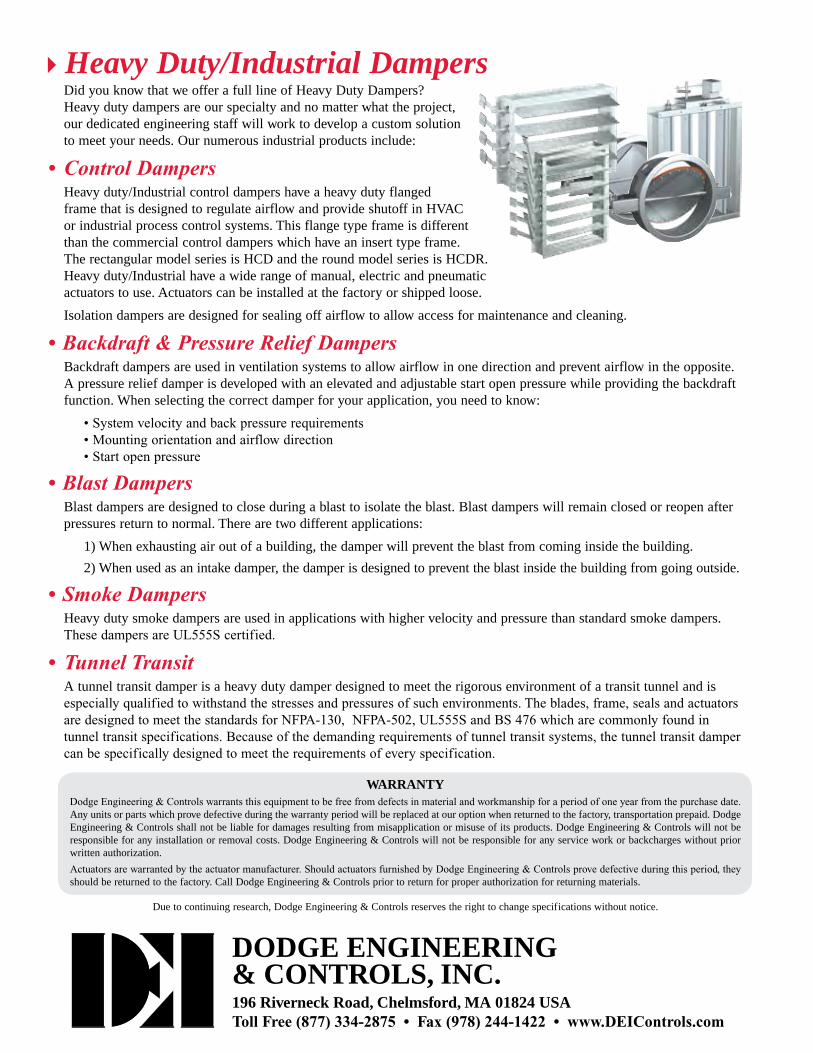
Heavy Duty/Industrial DampersDid you know that we offer a full line of Heavy Duty Dampers? Heavy duty dampers are our specialty and no matter what the project, our dedicated engineering staff will work to develop a custom solution to meet your needs. Our numerous industrial products include:
• ControlDampersHeavy duty/Industrial control dampers have a heavy duty flanged frame that is designed to regulate airflow and provide shutoff in HVAC or industrial process control systems. This flange type frame is different than the commercial control dampers which have an insert type frame. The rectangular model series is HCD and the round model series is HCDR. Heavy duty/Industrial have a wide range of manual, electric and pneumatic actuators to use. Actuators can be installed at the factory or shipped loose.
Isolation dampers are designed for sealing off airflow to allow access for maintenance and cleaning.
•Backdraft&PressureReliefDampersBackdraft dampers are used in ventilation systems to allow airflow in one direction and prevent airflow in the opposite. A pressure relief damper is developed with an elevated and adjustable start open pressure while providing the backdraft function. When selecting the correct damper for your application, you need to know:
�•�System�velocity�and�back�pressure�requirements •�Mounting�orientation�and�airflow�direction •�Start�open�pressure
•BlastDampersBlast dampers are designed to close during a blast to isolate the blast. Blast dampers will remain closed or reopen after pressures return to normal. There are two different applications:
1) When exhausting air out of a building, the damper will prevent the blast from coming inside the building.
2) When used as an intake damper, the damper is designed to prevent the blast inside the building from going outside.
•SmokeDampersHeavy duty smoke dampers are used in applications with higher velocity and pressure than standard smoke dampers. These�dampers�are�UL555S�certified.
• TunnelTransitA tunnel transit damper is a heavy duty damper designed to meet the rigorous environment of a transit tunnel and is especially�qualified�to�withstand�the�stresses�and�pressures�of�such�environments.�The�blades,�frame,�seals�and�actuators�are�designed�to�meet�the�standards�for�NFPA-130,��NFPA-502,�UL555S�and�BS�476�which�are�commonly�found�in�tunnel�transit�specifications.�Because�of�the�demanding�requirements�of�tunnel�transit�systems,�the�tunnel�transit�damper�can�be�specifically�designed�to�meet�the�requirements�of�every�specification.
WArrAntYDodge�Engineering�&�Controls�warrants�this�equipment�to�be�free�from�defects�in�material�and�workmanship�for�a�period�of�one�year�from�the�purchase�date.�Any units or parts which prove defective during the warranty period will be replaced at our option when returned to the factory, transportation prepaid. Dodge Engineering & Controls shall not be liable for damages resulting from misapplication or misuse of its products. Dodge Engineering & Controls will not be responsible for any installation or removal costs. Dodge Engineering & Controls will not be responsible for any service work or backcharges without prior written authorization.
Actuators�are�warranted�by�the�actuator�manufacturer.�Should�actuators�furnished�by�Dodge�Engineering�&�Controls�prove�defective�during�this�period,�they�should be returned to the factory. Call Dodge Engineering & Controls prior to return for proper authorization for returning materials.
Due to continuing research, Dodge Engineering & Controls reserves the right to change specifications without notice.


