VWEA16_Rogers_Hydraulic Considerations in Pumping System Design Hydraulic Considerations in Pumping System Design VWEA Wastewater Operations Education Conference Roanoke Virginia July 14, 2016
Transcript
VW
EA1
6_R
oge
rs_H
ydra
ulic
Co
nsi
der
atio
ns
in P
um
pin
g Sy
stem
Des
ign
Hydraulic Considerations in Pumping System DesignVWEA Wastewater Operations Education Conference
Roanoke Virginia
July 14, 2016
VW
EA1
6_R
oge
rs_H
ydra
ulic
Co
nsi
der
atio
ns
in P
um
pin
g Sy
stem
Des
ign
Agenda
• Basics of Hydraulics and Pump Operation
• Pumping System Design Process
• Types of Pumps
• System Curve Development
• Pump Station Layout
• Pump Selection Considerations
• Hydraulic Concerns
• Case Studies
• Summary
• Questions
VW
EA1
6_R
oge
rs_H
ydra
ulic
Co
nsi
der
atio
ns
in P
um
pin
g Sy
stem
Des
ign
Abbreviations and Acronyms
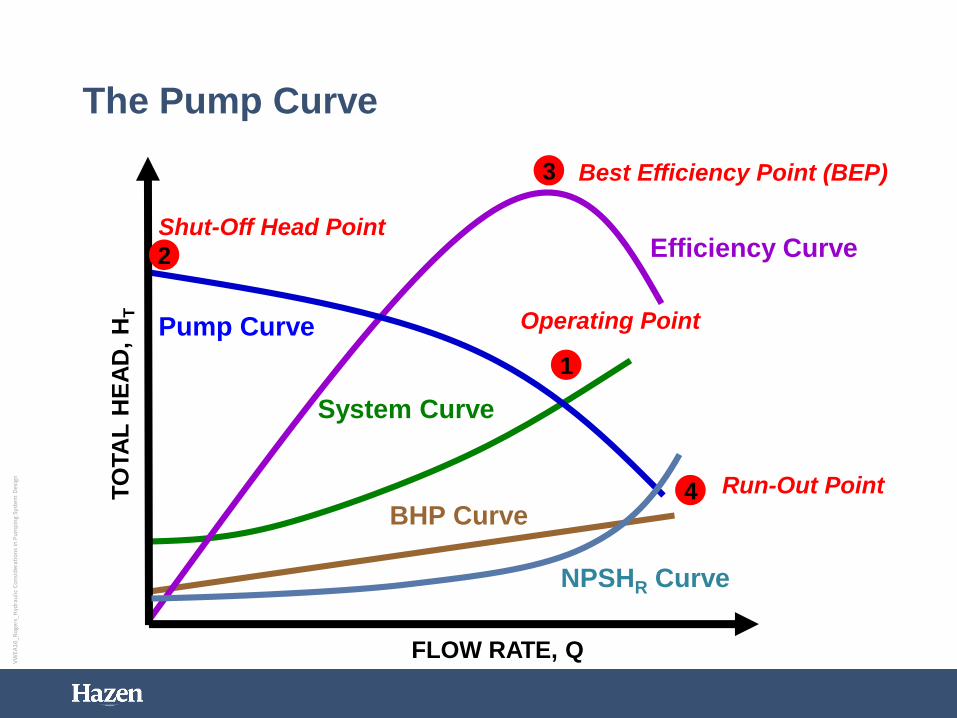
• BEP – best efficiency point
• BHP – brake horsepower
• fps or ft/sec – feet per second (velocity)
• FM – force main
• gpm – gallons per minute (flow)
• H – Head (feet)
• HP – horsepower
• n – rotational speed
• NPSHA – net positive suction head available
• NPSHR – net positive suction head required
• psi – pounds per square inch (pressure)
• Q – Flow Rate (gpm, mgd, cfs…)
• rpm – revolutions per minute
• TDH – total dynamic head
3
VW
EA1
6_R
oge
rs_H
ydra
ulic
Co
nsi
der
atio
ns
in P
um
pin
g Sy
stem
Des
ign
Basics of Pump Operation
• A pump lifts fluid from one elevation to another
• Work is needed to lift fluid
• Work is independent of type• Human Power• Animal Power• Wind Power• Steam Power• Electrical Power
• Pump can lift continuously or in increments
• Take-away:• Higher lift requires more work• Higher flow requires more work• Faster work requires more power
VW
EA1
6_R
oge
rs_H
ydra
ulic
Co
nsi
der
atio
ns
in P
um
pin
g Sy
stem
Des
ign
• Pumps deliver fluid against pressure
• Pressure = Force / Area (psi)
• Head (feet) is commonly used to express pump operating pressure
• A 2.31 foot high column of water exerts a pressure equal to 1 psi
• i.e. Car tires ~ 35 psi = 81 feet of head
VW
EA1
6_R
oge
rs_H
ydra
ulic
Co
nsi
der
atio
ns
in P
um
pin
g Sy
stem
Des
ign
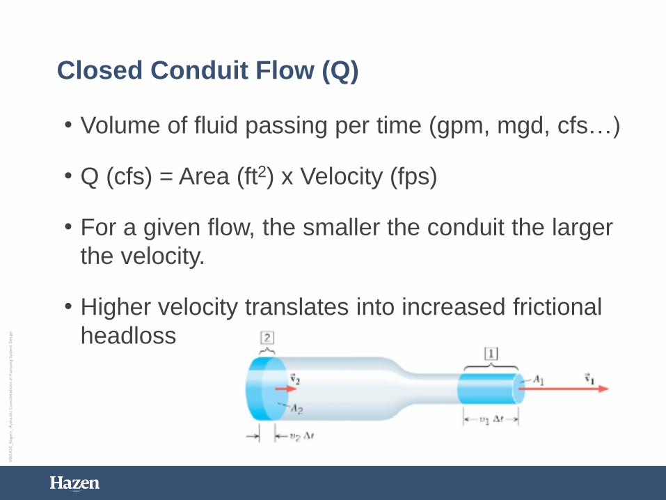
Closed Conduit Flow (Q)
• Volume of fluid passing per time (gpm, mgd, cfs…)
• Q (cfs) = Area (ft2) x Velocity (fps)
• For a given flow, the smaller the conduit the larger
the velocity.
• Higher velocity translates into increased frictional
headloss
VW
EA1
6_R
oge
rs_H
ydra
ulic
Co
nsi
der
atio
ns
in P
um
pin
g Sy
stem
Des
ign
• TDH is the total amount of head a pump must
operate against to deliver wastewater to a desired
location
• TDH = Static Head + Head Loss (HL)
• Static Head – exists when pump is on or off
• Head Loss – exists only when fluid is pumped
VW
EA1
6_R
oge
rs_H
ydra
ulic
Co
nsi
der
atio
ns
in P
um
pin
g Sy
stem
Des
ign
For free surfaces:
• Static Head = Discharge Tank WSEL – Suction Tank WSEL
• Static Discharge Head = Discharge Tank WSEL – Pump CL
• Static Suction Head = Suction Tank WSEL – Pump CL
Suction Lift – Negative Suction Head Flooded Suction – Positive Suction Head
VW
EA1
6_R
oge
rs_H
ydra
ulic
Co
nsi
der
atio
ns
in P
um
pin
g Sy
stem
Des
ign
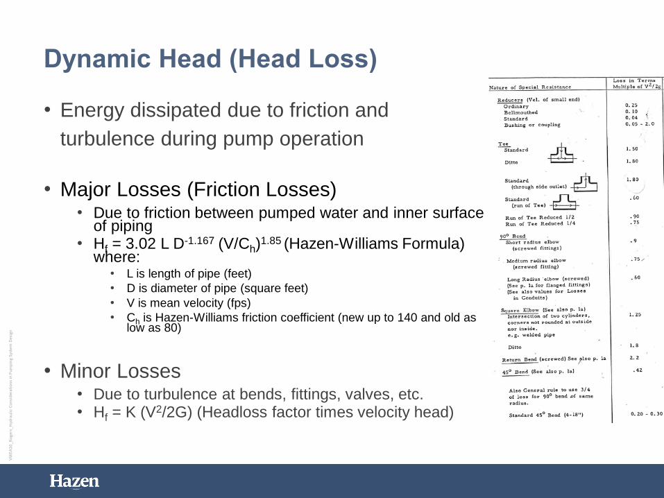
• Energy dissipated due to friction and
turbulence during pump operation
• Major Losses (Friction Losses)• Due to friction between pumped water and inner surface
of piping• Hf = 3.02 L D-1.167 (V/Ch)
1.85 (Hazen-Williams Formula) where:
• L is length of pipe (feet)
• D is diameter of pipe (square feet)
• V is mean velocity (fps)
• Ch is Hazen-Williams friction coefficient (new up to 140 and old as low as 80)
• Minor Losses• Due to turbulence at bends, fittings, valves, etc.• Hf = K (V2/2G) (Headloss factor times velocity head)
VW
EA1
6_R
oge
rs_H
ydra
ulic
Co
nsi
der
atio
ns
in P
um
pin
g Sy
stem
Des
ign
• NPSHA = Atmos. Head + Static Suction Head – Suction HL• Standard atmospheric pressure = 14.7 psi (34 ft. head)
• Net Positive Suction Head Required (NPSHR)• Furnished by pump manufacturer – pump specific
• Increases with pump flow
• NPSHA < NPSHR Cavitation• Typically occurs in systems with static lift
• Could occur in flooded suction scenario with extremely long lengths of suction piping
• Insufficient submergence can lead to vortexing
VW
EA1
6_R
oge
rs_H
ydra
ulic
Co
nsi
der
atio
ns
in P
um
pin
g Sy
stem
Des
ign
• Work• A force does work when it acts
on a body over a distance
• Units of foot pound (ft-lb)
• Wastewater pumps do work to move the wastewater
• Power• Rate of work done (ft-lb/s)
• Wastewater pumps most often do work by using electric motors
• Motors are commonly rated by horsepower (hp)
• 1 unit of hp is equal to 550 ft-lbs/s
VW
EA1
6_R
oge
rs_H
ydra
ulic
Co
nsi
der
atio
ns
in P
um
pin
g Sy
stem
Des
ign
The Pumping System Design Process
• Collect information
• Determine type of pump to be used
• Develop station layout
• Develop system curves
• Select pumps that match the system curves
• Write your specification
• Coordinate
• Finalize the design
12
VW
EA1
6_R
oge
rs_H
ydra
ulic
Co
nsi
der
atio
ns
in P
um
pin
g Sy
stem
Des
ign
Collect Information
• What – type of fluid is to be pumped?
• Fluid properties: density, viscosity, solids content, temperature
• From where to where?
• System characteristics: friction and minor losses, suction lift, static head, other pumps operating simultaneously
• How much – what are design flowrates?
13
VW
EA1
6_R
oge
rs_H
ydra
ulic
Co
nsi
der
atio
ns
in P
um
pin
g Sy
stem
Des
ign
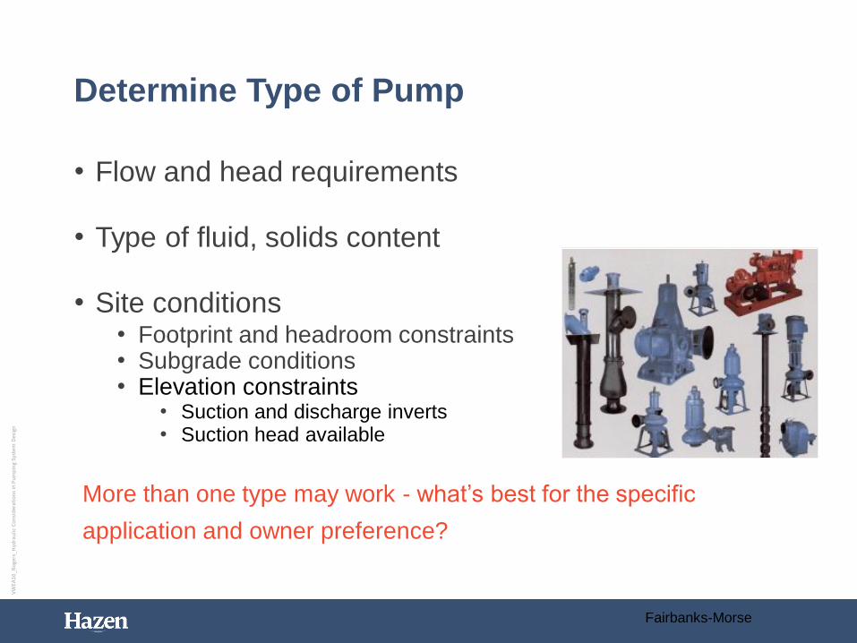
Determine Type of Pump
• Flow and head requirements
• Type of fluid, solids content
• Site conditions• Footprint and headroom constraints• Subgrade conditions• Elevation constraints
• Suction and discharge inverts• Suction head available
More than one type may work - what’s best for the specific
application and owner preference?
14
Fairbanks-Morse
VW
EA1
6_R
oge
rs_H
ydra
ulic
Co
nsi
der
atio
ns
in P
um
pin
g Sy
stem
Des
ign
Peripheral/Regenerative
Pumps
Jet
Gas lift
Hydraulic ram
Electromagnetic
Positive
Displacement
Kinetic
Centrifugal
Special
Single suction
Double suctionRadial Flow
Mixed Flow Self-priming
Non-self-priming
Axial Flow
Piston
Plunger
Diaphragm
Reciprocating
Rotary
Vane Screw
Gear Piston
Lobe Hose
Open impeller
Semi-open impeller
Closed impeller
Hydraulic Institute
Types of PumpsPump Types
15
VW
EA1
6_R
oge
rs_H
ydra
ulic
Co
nsi
der
atio
ns
in P
um
pin
g Sy
stem
Des
ign
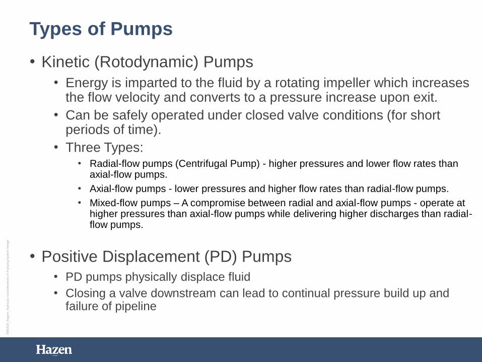
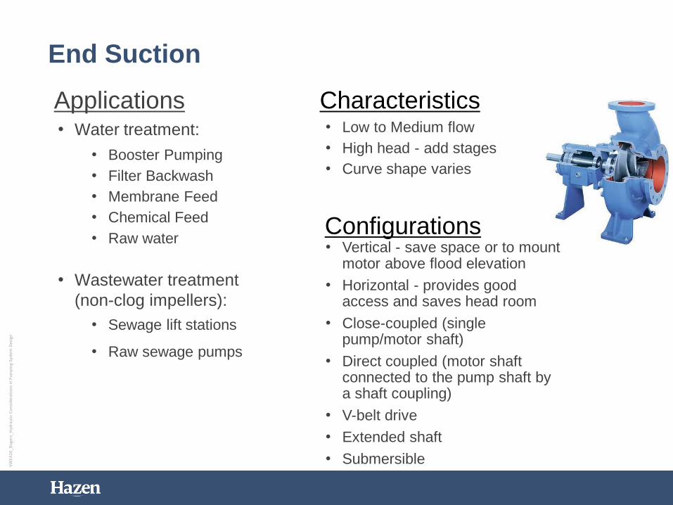
Types of Pumps
• Kinetic (Rotodynamic) Pumps
• Energy is imparted to the fluid by a rotating impeller which increases the flow velocity and converts to a pressure increase upon exit.
• Can be safely operated under closed valve conditions (for short periods of time).
• Three Types:• Radial-flow pumps (Centrifugal Pump) - higher pressures and lower flow rates than
axial-flow pumps.
• Axial-flow pumps - lower pressures and higher flow rates than radial-flow pumps.
• Mixed-flow pumps – A compromise between radial and axial-flow pumps - operate at higher pressures than axial-flow pumps while delivering higher discharges than radial-flow pumps.
• Positive Displacement (PD) Pumps
• PD pumps physically displace fluid
• Closing a valve downstream can lead to continual pressure build up and failure of pipeline
VW
EA1
6_R
oge
rs_H
ydra
ulic
Co
nsi
der
atio
ns
in P
um
pin
g Sy
stem
Des
ign
Positive Displacement Pumps
HP Reciprocating Triplex Pump
Lobe Pump Hose Pump
Progressing Cavity Pump
VW
EA1
6_R
oge
rs_H
ydra
ulic
Co
nsi
der
atio
ns
in P
um
pin
g Sy
stem
Des
ign
Progressing Cavity Pumps
• Flowrate fixed to speed
• Capable of pumping highly viscous stream
• Commonly used in sludge and slurry pumping
applications
• Operates at high pressures
• Must avoid running pump dry
• Provide safety features on discharge
VW
EA1
6_R
oge
rs_H
ydra
ulic
Co
nsi
der
atio
ns
in P
um
pin
g Sy
stem
Des
ign
Centrifugal PumpA centrifugal pump lifts fluid from one elevation to another by continuously
adding kinetic energy (accelerating the fluid) using a rotating impeller
• Several issues occur when operating outside these
ranges:
• Recirculation
• Excessive Noise
• Excessive Vibration
• Cavitation
• Pump Damage
VW
EA1
6_R
oge
rs_H
ydra
ulic
Co
nsi
der
atio
ns
in P
um
pin
g Sy
stem
Des
ign
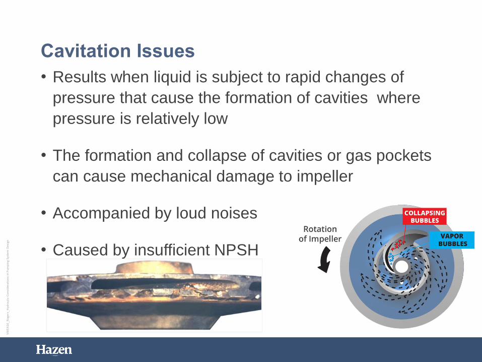
• Results when liquid is subject to rapid changes of
pressure that cause the formation of cavities where
pressure is relatively low
• The formation and collapse of cavities or gas pockets
can cause mechanical damage to impeller
• Accompanied by loud noises
• Caused by insufficient NPSH
VW
EA1
6_R
oge
rs_H
ydra
ulic
Co
nsi
der
atio
ns
in P
um
pin
g Sy
stem
Des
ign
Net Positive Suction Head (NPSH) –
Avoiding Cavitation
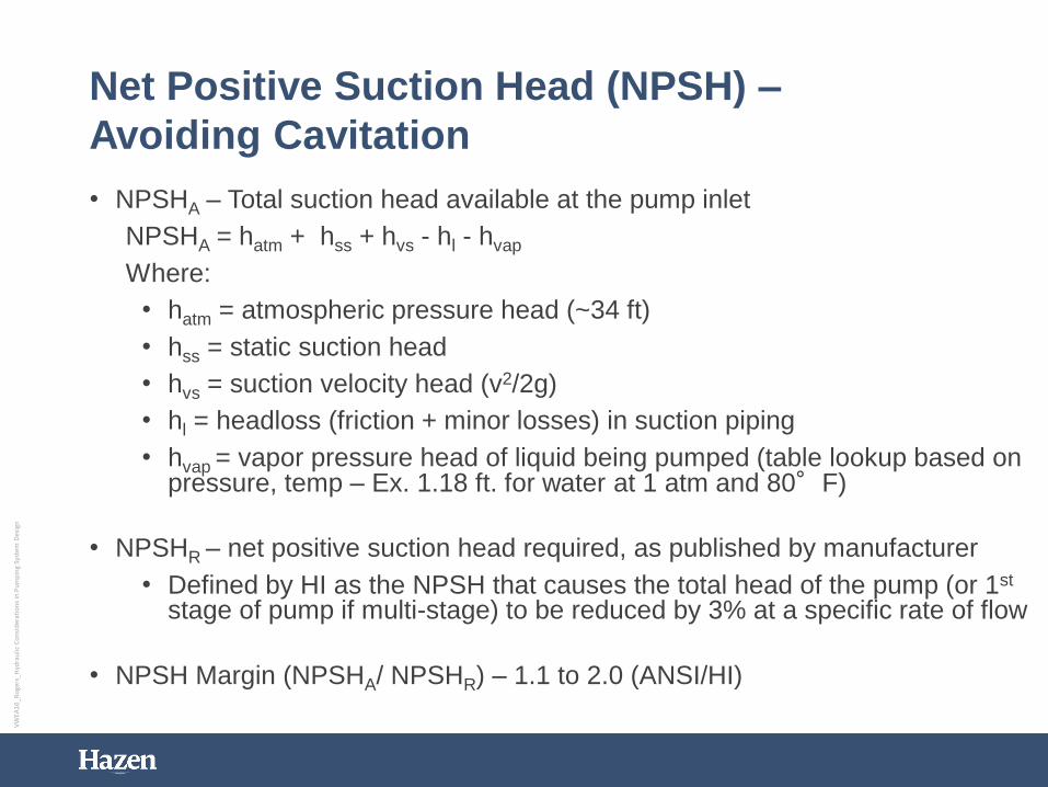
• NPSHA – Total suction head available at the pump inlet
NPSHA = hatm + hss + hvs - hl - hvap
Where:
• hatm = atmospheric pressure head (~34 ft)
• hss = static suction head
• hvs = suction velocity head (v2/2g)
• hl = headloss (friction + minor losses) in suction piping
• hvap = vapor pressure head of liquid being pumped (table lookup based on pressure, temp – Ex. 1.18 ft. for water at 1 atm and 80°F)
• NPSHR – net positive suction head required, as published by manufacturer
• Defined by HI as the NPSH that causes the total head of the pump (or 1st
stage of pump if multi-stage) to be reduced by 3% at a specific rate of flow
• NPSH Margin (NPSHA/ NPSHR) – 1.1 to 2.0 (ANSI/HI)
VW
EA1
6_R
oge
rs_H
ydra
ulic
Co
nsi
der
atio
ns
in P
um
pin
g Sy
stem
Des
ign
0
10
20
30
40
50
0 1000 2000 3000 4000
NP
SH
(ft
. a
bs.)
Flow (gpm)
Example Pumping StationSingle Pump Operating
NPSHA NPSHR
Example of NPSHA/ NPSHR
48
NPSHA/ NPSHR =
36 / 22 = 1.6
VW
EA1
6_R
oge
rs_H
ydra
ulic
Co
nsi
der
atio
ns
in P
um
pin
g Sy
stem
Des
ign
Correcting NPSH Problems
• Increase wetwell level or supply pressure
• Lower pump elevation
• Reduce headloss in suction piping• Check for blockages in pipe• Ensure that valves are operating correctly• Increase diameter of suction piping• Use long-radius bends
• Select (or run at) a lower speed pump
• Choose pump with larger suction diameter
49
VW
EA1
6_R
oge
rs_H
ydra
ulic
Co
nsi
der
atio
ns
in P
um
pin
g Sy
stem
Des
ign
• Also known as hydraulic shock or surge
• An oscillation in pressure resulting from a rapid increase
or decrease in flow (stopping pump, closing valve)
• Causes serious mechanical damage and loud noises
• Surge valves can help minimize water hammer
VW
EA1
6_R
oge
rs_H
ydra
ulic
Co
nsi
der
atio
ns
in P
um
pin
g Sy
stem
Des
ign
Water Hammer
Δh
VW
EA1
6_R
oge
rs_H
ydra
ulic
Co
nsi
der
atio
ns
in P
um
pin
g Sy
stem
Des
ign
Case Study – Flow Equalization Basin
• Prestressed Concrete Ground Storage Tank
• Pumped Influent, Gravity Drain
• Varying Water Levels Pose Hydraulic Challenges
40’ to 45’
VW
EA1
6_R
oge
rs_H
ydra
ulic
Co
nsi
der
atio
ns
in P
um
pin
g Sy
stem
Des
ign
0.00
10.00
20.00
30.00
40.00
50.00
60.00
70.00
80.00
90.00
100.00
0 10 20 30 40 50 60
TDH
(Fe
et)
Flow (MGD)
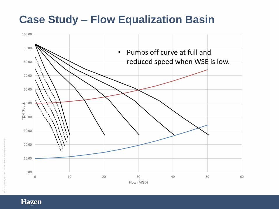
Case Study – Flow Equalization Basin
• Pumps off curve at full and reduced speed when WSE is low.
VW
EA1
6_R
oge
rs_H
ydra
ulic
Co
nsi
der
atio
ns
in P
um
pin
g Sy
stem
Des
ign
0.00
10.00
20.00
30.00
40.00
50.00
60.00
70.00
80.00
90.00
100.00
0 10 20 30 40 50 60
TDH
(Fe
et)
Flow (MGD)
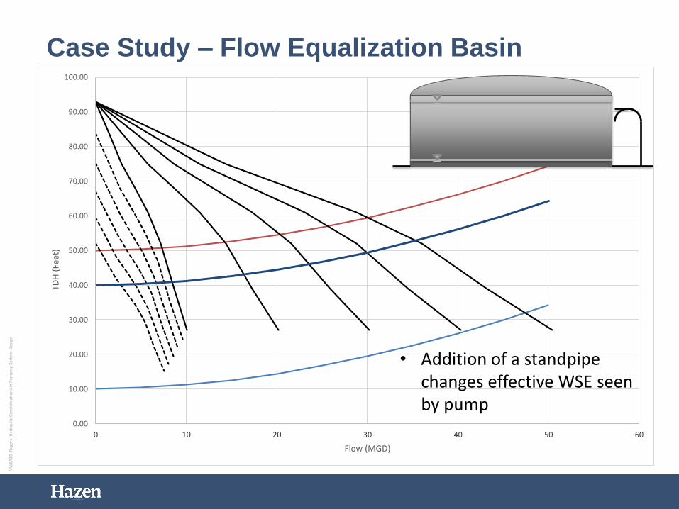
Case Study – Flow Equalization Basin
• Addition of a standpipe changes effective WSE seen by pump
VW
EA1
6_R
oge
rs_H
ydra
ulic
Co
nsi
der
atio
ns
in P
um
pin
g Sy
stem
Des
ign
Case Study – DC Water Blue Plains FADF
FIP System
• (10) 100 MGD Vertical Turbine Pumps
• Magnetic Drives limit to 90% turndown
• Insufficient Submergence
• Pumps, motors and mag drives at end of life
• Slamming of check valves
• Undersized air and vacuum valves
• Proposed System:
• (10) 70 MGD Constant Speed Pumps
• (2) 50 MGD Pumps (VFD’s)
• Premium Efficiency Motors
• New Medium Voltage Electrical Facility
• Increase in Forebay WSE
• Floating Datum Concept
• Refine Control Strategy
VW
EA1
6_R
oge
rs_H
ydra
ulic
Co
nsi
der
atio
ns
in P
um
pin
g Sy
stem
Des
ign
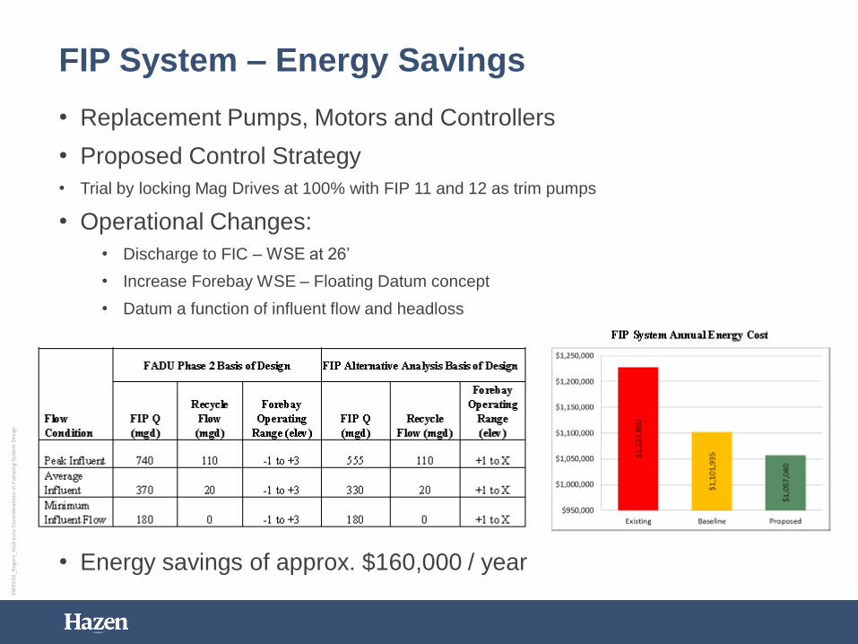
FIP System – Energy Savings
• Replacement Pumps, Motors and Controllers
• Proposed Control Strategy
• Trial by locking Mag Drives at 100% with FIP 11 and 12 as trim pumps
• Operational Changes:
• Discharge to FIC – WSE at 26’
• Increase Forebay WSE – Floating Datum concept
• Datum a function of influent flow and headloss
• Energy savings of approx. $160,000 / year
VW
EA1
6_R
oge
rs_H
ydra
ulic
Co
nsi
der
atio
ns
in P
um
pin
g Sy
stem
Des
ign
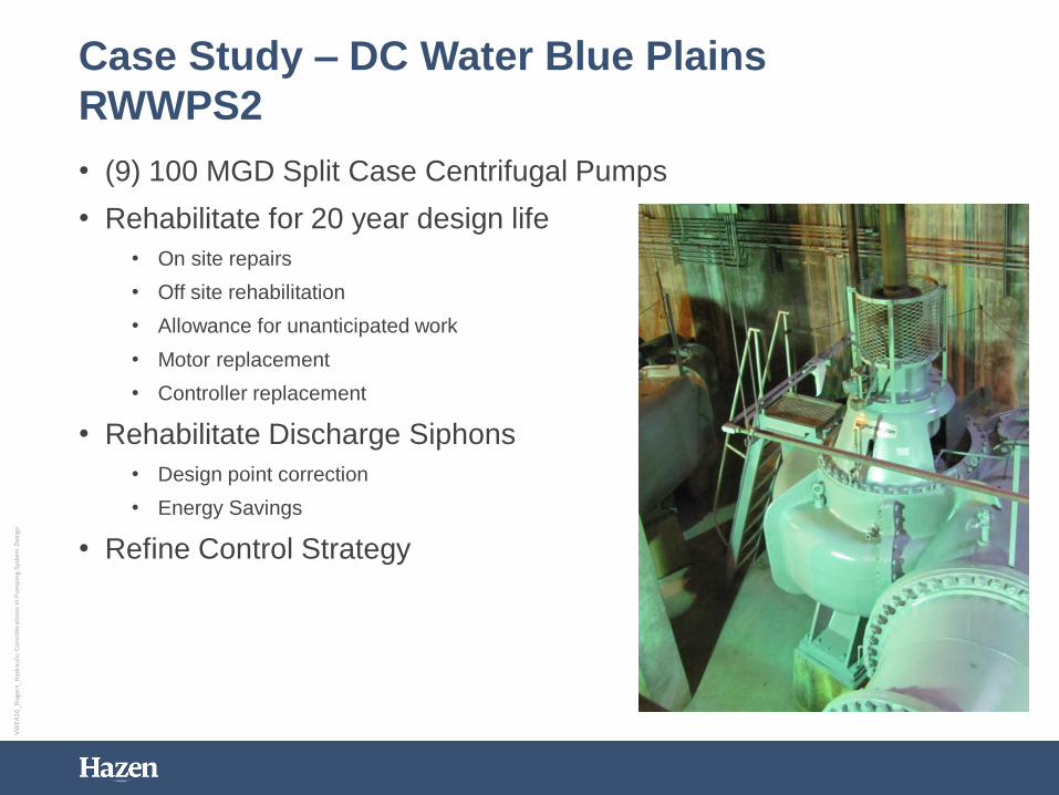
Case Study – DC Water Blue Plains
RWWPS2
• (9) 100 MGD Split Case Centrifugal Pumps
• Rehabilitate for 20 year design life
• On site repairs
• Off site rehabilitation
• Allowance for unanticipated work
• Motor replacement
• Controller replacement
• Rehabilitate Discharge Siphons
• Design point correction
• Energy Savings
• Refine Control Strategy
VW
EA1
6_R
oge
rs_H
ydra
ulic
Co
nsi
der
atio
ns
in P
um
pin
g Sy
stem
Des
ign
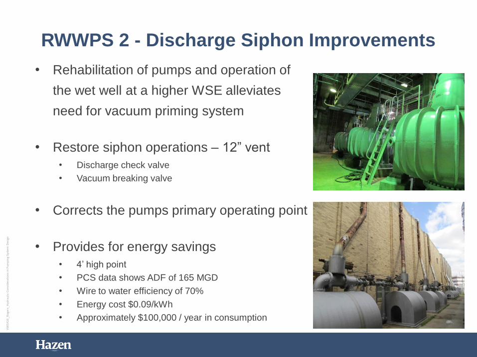
RWWPS 2 - Discharge Siphon Improvements
• Rehabilitation of pumps and operation of
the wet well at a higher WSE alleviates
need for vacuum priming system
• Restore siphon operations – 12” vent
• Discharge check valve
• Vacuum breaking valve
• Corrects the pumps primary operating point
• Provides for energy savings
• 4’ high point
• PCS data shows ADF of 165 MGD
• Wire to water efficiency of 70%
• Energy cost $0.09/kWh
• Approximately $100,000 / year in consumption
VW
EA1
6_R
oge
rs_H
ydra
ulic
Co
nsi
der
atio
ns
in P
um
pin
g Sy
stem
Des
ign
Summary – Pump and System Curves
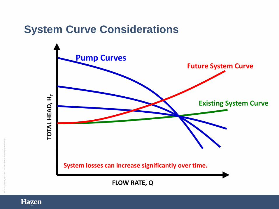
• There will be several system curves – explore all
boundaries – low and high flow / elevations, existing
and future C-factors
• Use real elevations for system curves (not pump TDH)
• Avoid flat pump curves if VFDs to be used
• Use affinity laws to explore speed impacts
• Duty point to be ~75% Qmax, close to BEP
• Aim for efficiencies > 75% single stage
59
VW
EA1
6_R
oge
rs_H
ydra
ulic
Co
nsi
der
atio
ns
in P
um
pin
g Sy
stem
Des
ign
Summary - Centrifugal Pump Selection
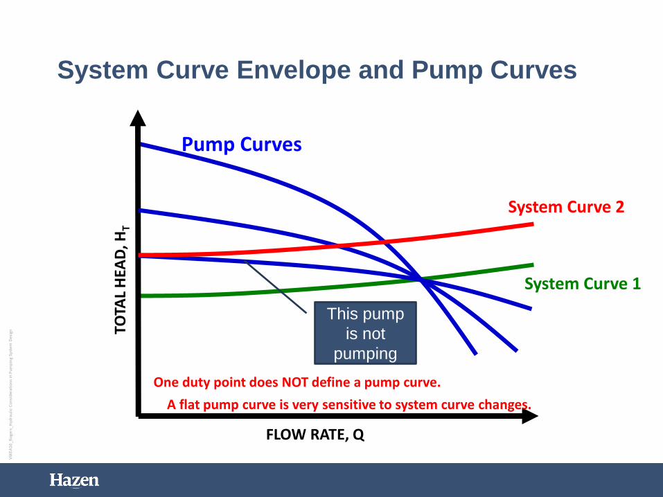
• Single duty point is insufficient to specify pump
• Give secondary points for VFD reduced speed curves
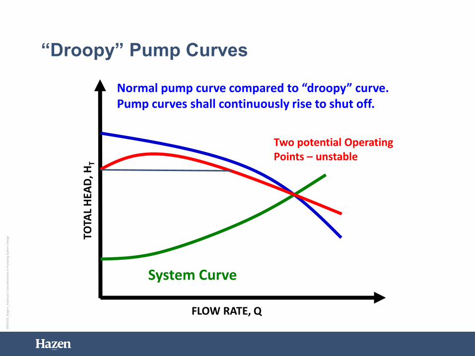
• No droopy curves – unstable operation - “shall
continuously rise to shut off”
• Size motors for Run Out / Maximum HP
• Make sure pump motors are inverter-rated if using VFDs
• Pump motors can be noisy and generate heat (VFDs too)
VW
EA1
6_R
oge
rs_H
ydra
ulic
Co
nsi
der
atio
ns
in P
um
pin
g Sy
stem
Des
ign
Summary - Good Hydraulic Design
• Develop system curves early
• Get real data – measure, survey, test
• Follow HI Standards
• The best flow path is a smooth one
• Don’t forget NPSH – no cavitation!
• Consider surge pressure in design
• Consider the full range of possible operating conditions,
now and future
• Provide flexibility and expandability
• Work with vendors and O&M staff
• Iterative process
61
VW
EA1
6_R
oge
rs_H
ydra
ulic
Co
nsi
der
atio
ns
in P
um
pin
g Sy
stem
Des
ign
Acknowledgements / Useful Web Sites
• Hydraulic Institute Standards – www.pumps.org
• Books: Pumping Station Design – Sanks, Perry’s
Chemical Engineers’ Handbook, Cameron Hydraulic
Data, etc.
• Other useful websites:
• www.pump-zone.com
• www.pumped101.com
• www.mcnallyinstitute.com
• www.pumpcalcs.com
• www.eere.energy.gov
• Hazen colleagues - Brian Porter, Bryan Lisk and Ellen