75
GRUNDFOS INSTRUCTIONS Hydro MPC BoosterpaQ ® Installation and operating instructions

GRUNDFOS INSTRUCTIONS
Hydro MPC BoosterpaQ®
Installation and operating instructions
De
cla
ratio
n o
f co
nfo
rmity
2
Declaration of conformity
Declaration of ConformityWe, Grundfos, declare under our sole responsibility that the products
Hydro MPC, to which this declaration relates, are in conformity with these Council directives on the approximation of the laws of the EC member
states:
—Machinery Directive (2006/42/EC).Standards used: EN 809: 1998 and EN 60204-1: 2006.
—EMC Directive (2004/108/EC).Attestation of conformity: Certificate Hydro MPC 2: 2009.
Bjerringbro, 29th December 2009
Svend Aage KaaeTechnical Director

En
gli
sh
(U
S)
English (US) Installation and operating instructionsOriginal installation and operating instructions.
CONTENTSPage
1. Symbols used in this document
2. Product introduction
As standard, Hydro MPC booster systems consist of two to six CR(E) pumps coupled in parallel and mounted on a common base frame with all the necessary fittings and a control cabinet.
Fig. 1 Hydro MPC booster system
1. Symbols used in this document 3
2. Product introduction 32.1 Control variant 4
3. Identification 43.1 Nameplate 43.2 Software label 53.3 Type key 6
4. Overview of control variants 7
5. Delivery and handling 85.1 Delivery 85.2 Handling 8
6. Installation 86.1 Mechanical installation 86.2 Electrical installation 96.3 Start-up 10
7. Control panel 127.1 Display 127.2 Buttons and indicator lights 13
8. Functions 148.1 Tree of functions 148.2 Overview 168.3 Description of functions 188.4 Status (1) 188.5 Operation (2) 228.6 Alarm (3) 288.7 Settings (4) 338.8 Data communication 67
9. External variable frequency drive 699.1 *VLT FC 202 699.2 Configuration of E-pump(s), if any 70
10. Fault finding 71
11. Maintenance 7211.1 CU 352 7211.2 Pumps 7211.3 Motor bearings 72
12. Frost protection 72
13. Shutdown 72
14. Technical data 7214.1 Pressure 7214.2 Temperature 7214.3 Relative humidity 7214.4 Sound pressure 72
15. Electrical data 73
16. Further product documentation 73
17. Disposal 73
Warning
Prior to installation, read these installation and operating instructions. Installation and operation must comply with local regulations and accepted codes of good practice.
Warning
If these safety instructions are not observed, it may result in personal injury.
Warning
If these instructions are not observed, it may lead to electric shock with consequent risk of serious personal injury or death.
CautionIf these safety instructions are not observed, it may result in malfunction or damage to the equipment.
NoteNote Notes or instructions that make the job easier and ensure safe operation.
NoteNote A diaphragm tank is required in most installations.
TM
04
411
0 0
71
2
Pos. Description Quantity
1 Control panel 1
2 Nameplate 1
3 Suction manifold (stainless steel) 1
4 Isolating valve 2 per pump
5 Base frame (stainless steel) 1
6 Non-return valve 1 per pump
7 Discharge manifold (stainless steel) 1
8 Pressure transmitter/pressure gauge 1
9 Pump 2 - 6
3

En
glis
h (U
S)
2.1 Control variant
Hydro MPC booster systems are divided into three groups based on the control variant:
Note: Horsepower range of CRE pumps depends on incoming power voltage.
•1 x 230V / 60 Hz, 0.5 → 1.5 Hp
•3 x 208-230V / 60 Hz, 1.5 → 7.5 HP
•3 x 460V / 60 Hz, 1 → 30 Hp
See also section 4. Overview of control variants.
Hydro MPC booster systems always include application-optimized software for setting the booster system to the application in question.
3. Identification
3.1 Nameplate
The nameplate is fitted on the base frame. See position 2 in fig. 1.
Fig. 2 Nameplate
Control variant
Description
-E
Two to six electronically speed-controlled pumps. Hydro MPC-E systems equipped with CRE pumps include integrated frequency drive/motors. Horsepower range of CRE pumps depend on incoming power voltage, see note below. Hydro MPC-E equipped with CR pumps are connected to Grundfos CUE variable frequency drive (one per pump).
-FTwo to six CR pumps connected to a Grundfos CUE frequency drive. The speed-controlled operation alternates between the pumps.
-S Two to six constant speed CR pumps.
TM
03
17
41
07
12
Pos. Description
1 Type designation
2 Model
3 Serial number
4 Supply voltage
5 Maximum operating pressure [psi]
6 Liquid temperature [°F]
7 Maximum flow rate [gpm]
8 Minimum head [feet]
9 Number of fixed speed pumps
10 Motor power [HP] of fixed speed pumps
11 Rated voltage [V] of fixed speed pumps
12 Number of pumps with frequency drive
13 Motor power [HP] of pumps with frequency drive
14 Rated voltage [V] of pumps with frequency drive
15 Number of pilot pumps
16 Motor power [HP] of pilot pumps
17 Rated voltage [V] of pilot pumps
18 Order number
19-24 Options
25 Enclosure class
26 Weight in lbs.
27 Approval mark
28 Production location and date code
4

En
gli
sh
(U
S)
3.2 Software labelThe software label is placed on the back of the CU 352 controller.
Fig. 3 Software label
* Applies only to booster systems.
** Applies only to CR and CRE pumps.
TM
03
17
42
31
05
Pos. Description
1 Control MPC - GSC file number
2 Control MPC options - GSC file numbers
3 Hydro MPC - GSC file number *
4 Hydro MPC options - GSC file numbers *
5 Pump data - GSC file numbers **
NoteNote A GSC (Grundfos Standard Configuration) file is a configuration data file.
1. Control MPC 3. Hydro MPC
5. Pump data
96586126
4. H-MPC options2. C-MPC options
CONFIGURATION STEPS - PLEASE FOLLOW THE NUMBERS
1
2
3
4 5
5

En
glis
h (U
S)
3.3 Type key
Example Hydro MPC -E 3 CRE 5-8 3 x 208-230 V, 50/60 Hz
Type range
Control variantsE: Pumps with integrated frequency driveE: Pumps connected to a Grundfos CUE frequency drive - one per pumpF: Pumps connected to one Grundfos CUE frequency driveS: Fixed speed pumps (start/stop)
Number of pumps with integrated frequency drive and pump type
Number of fixed speed pumps and pump type
Supply voltage, frequency
6
En
gli
sh
(U
S)
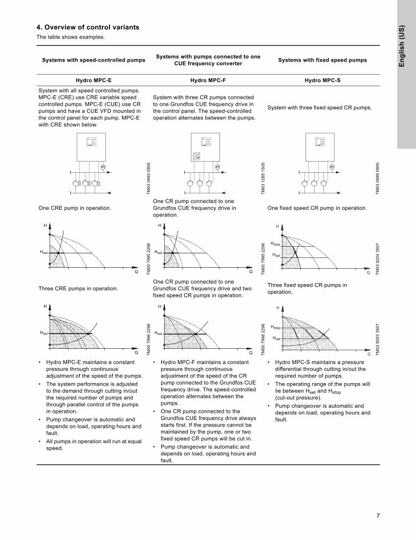
4. Overview of control variantsThe table shows examples.
Systems with speed-controlled pumpsSystems with pumps connected to one
CUE frequency converterSystems with fixed speed pumps
Hydro MPC-E Hydro MPC-F Hydro MPC-S
System with all speed controlled pumps. MPC-E (CRE) use CRE variable speed controlled pumps. MPC-E (CUE) use CR pumps and have a CUE VFD mounted in the control panel for each pump. MPC-E with CRE shown below.
System with three CR pumps connected to one Grundfos CUE frequency drive in the control panel. The speed-controlled operation alternates between the pumps.
System with three fixed speed CR pumps.
TM
03
09
93
09
05
TM
03
12
65
15
05
TM
03
09
99
09
05
One CRE pump in operation.One CR pump connected to one Grundfos CUE frequency drive in operation.
One fixed speed CR pump in operation.
TM
00
79
95
22
96
TM
00
79
95
22
96
TM
03
92
04
35
07
Three CRE pumps in operation.One CR pump connected to one Grundfos CUE frequency drive and two fixed speed CR pumps in operation.
Three fixed speed CR pumps in operation.
TM
00
79
96
22
96
TM
00
79
98
22
96
TM
03
90
03
35
07
• Hydro MPC-E maintains a constant pressure through continuous adjustment of the speed of the pumps.
• The system performance is adjusted to the demand through cutting in/out the required number of pumps and through parallel control of the pumps in operation.
• Pump changeover is automatic and depends on load, operating hours and fault.
• All pumps in operation will run at equal speed.
• Hydro MPC-F maintains a constant pressure through continuous adjustment of the speed of the CR pump connected to the Grundfos CUE frequency drive. The speed-controlled operation alternates between the pumps.
• One CR pump connected to the Grundfos CUE frequency drive always starts first. If the pressure cannot be maintained by the pump, one or two fixed speed CR pumps will be cut in.
• Pump changeover is automatic and depends on load, operating hours and fault.
• Hydro MPC-S maintains a pressure differential through cutting in/out the required number of pumps.
• The operating range of the pumps will lie between Hset and Hstop (cut-out pressure).
• Pump changeover is automatic and depends on load, operating hours and fault.
PT PT PT
Q
H
Hset
Q
H
Hset
Q
H
Hstop
Hset
Q
H
Hset
Q
H
Hset
Q
H
Hstop
Hset
7

En
glis
h (U
S)
5. Delivery and handling
5.1 Delivery
Depending on size, the booster system is delivered in an open wooden box or wooden/cardboard box designed for transport by forklift truck or a similar vehicle.
5.2 Handling
Hydro MPC booster systems with CR 120 or 150 pumps have eyebolts in the base frame. See fig. 4.
The lifting point should always be above the center of gravity of the booster system.
Each lifting strap must be at least three meters long.
Fig. 4 Correct lifting of Hydro MPC XL
Use suitable lifting equipment that is in good condition and approved for the weight. The weight is stated on the nameplate of the booster system.
6. InstallationBefore installation, check the following:
• That the booster system is as ordered.
• That no visible parts have been damaged.
6.1 Mechanical installation
6.1.1 Location
The booster system must be installed in a well-ventilated room to ensure sufficient cooling of the pumps and control cabinet.
The booster system must have a 3-foot clearance in front and on the two sides for inspection and dismantling.
6.1.2 Pipework
Arrows on the pump base show the direction of flow of water through the pump.
The pipework connected to the booster system must be of adequate size. The pipes are connected to the manifolds of the booster system. Either end can be used. Apply sealing compound to the unused end of the manifold, and fit the screw cap.For manifolds with flanges, fit a blanking flange with gasket.
To achieve optimum operation and minimiz6e noise and vibration, it may be necessary to consider vibration dampening of the booster system.
Noise and vibration are generated by the rotations in the motor and pump and by the flow in pipework and fittings. The effect on the environment is subjective and depends on correct installation and the state of the other parts of the system.
If booster systems are installed in blocks of flats or the first consumer on the line is close to the booster system, we recommend to fit expansion joints on the suction and discharge pipes to prevent vibration being transmitted through the pipework.
Fig. 5 Sketch showing the position of expansion joints, pipe supports and machine shoes
All nuts should be tightened prior to start-up.
Fasten the pipes to parts of the building to ensure that they cannot move or be twisted.
6.1.3 Foundation
The booster system should be positioned on an even and solid surface, for instance a concrete floor or foundation. If the booster system is not fitted with machine shoes, it must be bolted to the floor or foundation.
Hydro MPC booster systems with CR 120 or CR 150 pumps are secured by means of transport straps. Do not remove these transport straps until the booster system has been installed.
TM
04
41
88
10
09
Warning
When lifting Hydro MPC booster systems with CR 120 or CR 150 pumps, never use the eyebolts of the motors.
Do not lift the booster system by the manifolds, but according to fig. 4.
CautionDo not use chains for lifting booster systems with CR 120 or CR 150 pumps, as the motors of the pumps can be damaged.
CautionThe Hydro MPC is not designed for outdoor installation unless protected, and must not be exposed to direct sunlight.
TM
03
21
54
38
05
Pos. Description
1 Expansion joint
2Pipe support, and good location for system isolation valve (not shown)
3 Machine shoe
NoteNoteExpansion joints, pipe supports and machine shoes shown in the figure above are not supplied with a standard booster system.
NoteNoteAs a rule of thumb, the weight of a concrete foundation should be 1.5 x the weight of the booster system.
2
11
3 3
2
8

En
gli
sh
(U
S)
6.1.4 Vibration dampersTo prevent the transmission of vibrations to buildings, it may be necessary to isolate the booster system foundation from building parts by means of vibration dampers.
Which is the right damper varies from installation to installation, and a wrong damper may increase the vibration level. Vibration dampers should therefore be sized by the supplier of vibration dampers. If the booster system is installed on a base frame with vibration dampers, expansion joints should always be fitted on the manifolds. This is important to prevent the booster system from "hanging" in the pipework.
6.1.5 Expansion joints
Expansion joints are installed for the following reasons:
• to absorb expansions/contractions in the pipework caused by changing liquid temperature
• to reduce mechanical strains in connection with pressure surges in the pipework
• to isolate mechanical structure-borne noise in the pipework (only rubber bellows expansion joints).
Fit expansion joints at a distance of minimum 1 to 1 1/2 times the nominal flange diameter from the manifold on the suction as well as on the discharge side. This prevents the development of turbulence in the expansion joints, resulting in better suction conditions and a minimum pressure loss on the pressure side.
Fig. 6 Examples of rubber bellows expansion joints without and with limiting rods
Expansion joints with limiting rods can be used to minimize the forces caused by the expansion joints. Recommend expansion joints with limiting rods for flanges larger than 6 inches.
The pipework should be anchored so that it does not stress the expansion joints and the pump. Follow the supplier’s instructions and pass them on to advisers or pipe installers.
6.2 Electrical installation
• Make sure that the booster system is suitable for the electricity supply to which it is connected.
• Make sure that the wire cross-section corresponds to the specifications in the wiring diagram.
The connection of the electrical supply, transmitters and external monitoring equipment must be carried out by an authorized electrician in accordance with the NEC, local regulations and the BoosterpaQ wiring diagram.
Ensure that the Hydro MPC controls and the pumps are suitable for the electricity supply on which they will be used (see Technical Data). Please read the wiring diagram carefully. According to the NEC, if the motors cannot be seen from the control panel, they must be fitted with a disconnect switch.
Any BoosterpaQ that utilizes a variable frequency drive (E, ED, ES, EF, EDF, F) should be connected to an electrical supply with all phase lines electrically symmetrical with respect to ground. A "four wire wye" electrical supply with line impedance between 0.5% - 3% is recommended. If a variable frequency drive is connected to a delta transformer or if line impedance is not within the recommended 0.5% - 3%, the drive may not operate correctly and may not provide optimum performance (excessive faults, erratic behavior, or complete failure). "Open delta" power is not recommended. Ask your power company or electrician to determine what type of electrical supply is present. Generator supplied power must meet public utility power quality standards.
NoteNoteExpansion joints must not be installed to compensate for inaccuracies in the pipework such as center displacement of flanges.
TM
02
49
81
19
02
- T
M0
2 4
97
9 1
90
2
Warning
The electrical installation should be carried out by an authorized person in accordance with local regulations and the relevant wiring diagram.
9

En
glis
h (U
S)
6.3 Start-up
1. Have a qualified person check for proper power supply and plumbing connections. Make sure the main power is off.
2. Check that the air pre-charge in the diaphragm tank is 0.7 times the required discharge pressure set-point (0.9 times for MPC-S systems). System pressure must not be applied to the tank connection during the tank precharge process. If water is supplied to the tank from the system, close the tank valve and bleed off the pressure in the tank before the pressurizing process.
Prime the system as follows
3. Suction pressure system (pumps are flooded at least as high as the highest part of the pumps)
– close all discharge manifold pump isolation valves and open all inlet manifold pump isolation valves
– open the vent plug on top of each pump. It is a small hex head screw in a large vent plug. Air and water will escape from the pump through a small hole in the large vent plug. When the air is out and water is flowing steadily, tighten the small hex head screw on the vent plug.
4. Suction lift system (the water source is below the pumps or does not flood the pumps to the highest point on the pumps).
– close all discharge manifold pump isolation valves and open all inlet manifold pump isolation valves
– for suction lift applications, a foot valve must be placed on the inlet piping at the water source (tank, etc). If there is a fill point above the highest point of the pumps, you may fill the system from this point. If there is no fill point above the highest point of the pumps, remove the large vent plug on each pump. Fill each pump until the water is up to the vent plug, then replace the vent plugs.
5. Ensure all circuit breakers are in the "on" position.
6. Make sure the discharge manifold pump isolation valves are closed. Switch on main power.
7. If this is the first time the system has been powered on, the "Start-up wizard" may appear. Once you have completed the wizard, you may skip Step 8. If the wizard does not appear, please proceed to Step 8.
8. Run the "Start-up wizard" again by performing the following: Move top line display to "Settings". If prompted for password, enter "1234", next move down to "Functions, CU352" and press the "OK" button. Now move down to "Run wizard again" and press the "OK" button.
9. Vent the system by opening the vent plug on each pump (as in Step 3, while the pump is running starting in step 18 of the "Start-up wizard"). Venting with the pumps running ensures all air is removed from the suction piping. Do not run the system with the discharge manifold pump isolation valves closed more than five minutes to prevent over-heating of the pump liquid.
10. As pumps stop, check pump rotation. Repeat as necessary. If the area is dark, a flashlight may be required, or remove a coupling guard on each pump for better visibility. Disconnect the main power when removing coupling guards.
If the rotation is incorrect on any 3 phase pumps, switch any 2 of the 3 power main wires supplied to the control panel (L1, L2, L3). If that doesn’t correct the rotation, call your Grundfos representative.
11. Upon completion of venting pumps and checking for correct rotation you are now ready to bring the BoosterpaQ into normal operation. With the discharge manifold isolation valves still closed, partially open each pump discharge isolation valve to allow water to enter into the discharge piping. Continue the process of filling the discharge piping until discharge piping pressure is approximately at the desired Setpoint pressure of the system.
12. Open pump discharge isolation valves completely. System is now ready for operation.
It may be necessary to clear alarms in the fault log. Follow the stops in paragraph sections 9.6 to clear arms.
NoteNoteExpansion joints must not be installed to compensate for inaccuracies in the pipework such as center displacement of flanges.
Caution The pumps may start at this time.
Warning
Do not touch the couplings while the pumps are turning as injury may result. Replace all coupling guards after the rotation check. Disconnect main power when removing and replacing coupling guards (or open service disconnect switches if this option was supplied).
NoteNoteIf you are filling an empty piping system, do not allow the pumps to run with the discharge valves wide open as cavitation may occur.
10

En
gli
sh
(U
S)
Installation and Startup Notes11

En
glis
h (U
S)
7. Control panelThe control panel in the front cover of the control cabinet features a display, a number of buttons and two indicator lights.The control panel enables manual setting and monitoring of the performance of the system.
Fig. 7 Control panel
7.1 Display
Fig. 8 Display design
7.1.1 Menu line
The menu line (A) is illustrated in fig. 8.
The display has four main menus:
7.1.2 Top line
The top line (B) is illustrated in fig. 8. It shows the following:
• the display number and title (left side)
• the selected menu (left side)
• the symbol in case of alarm (right side)
• the symbol in case of warning (right side)
• the symbol if the service language has been selected(right side).
7.1.3 Graphical illustration
The graphical illustration (D) may show a status, an indication or other elements, depending on the position in the menu structure.
The illustration may show the entire system or part of it as well as various settings.
7.1.4 Scroll bar
If the list of illustration elements exceeds the display, the symbols and will appear in the scroll bar to the right. Move up and
down in lists with these symbols.
7.1.5 Bottom line
The bottom line (C) shows the date and time.
TM
05
30
43
08
12
Pos. Description
1 Display
2 Arrow to the right
3 Help
4 Up
5 Down
6 Plus
7 Minus
8 Back
9 Home
10 OK
11 Indicator light, operation (green)
12 Indicator light, fault (red)
13 Brightness
1
111098764532
1213
CU 352
Status Indication of system status
Operation Change of operating parameters such as setpoint
Alarm Alarm log for fault finding
Settings Change of settings (password option)
AB
D
C
12

En
gli
sh
(U
S)
7.2 Buttons and indicator lightsThe buttons (pos. 2 to 10 in fig. 7) on the CU 352 are active when they are lit.
7.2.1 Arrow to the right (pos. 2)
Press [>] to go to the next menu in the menu structure. If you press [>] when menu "Settings" is highlighted, you will go to menu "Status".
7.2.2 Help (pos. 3)
When this symbol is lit, a help text applying to the display will appear if you press the button.
Close the text with .
7.2.3 Up and down (pos. 4 and 5)
Move up and down in lists with [ ∨ ] and [ ∧ ].
You can select a text with [ok] when it is in a box.
If a text is marked and you press [ ∧ ], the text above will be marked. If you press [ ∨ ], the text below will be marked.
If you press [ ∨ ] in the last line in the list, the first line will be marked.
If you press [ ∧ ] in the first line in the list, the last line will be marked.
7.2.4 Plus and minus (pos. 6 and 7)
Increase and reduce a value with [+] and [-]. Save with [ok].
7.2.5 Back (pos. 8)
Press to go one display back in the menu.
If you have changed a value and press , the new value will not be saved. See also section 7.2.7 OK (pos. 10).
If you press [ok] before pressing , the new value will be saved. See also section 7.2.7 OK (pos. 10).
7.2.6 Home (pos. 9)
Press to return to menu "Status".
7.2.7 OK (pos. 10)
Use the button as an enter button.
The button is also used to start the setting of a value. If you have changed a value, you must press [ok] to save the change.
7.2.8 Indicator lights (pos. 11 and 12)
The control panel incorporates a green and red indicator light.
The green indicator light will be on when the system is in operation and flash when the system has been set to stop.
The red indicator light will be on if there is an alarm or a warning. The fault can be identified from the alarm list.
7.2.9 Brightness (pos. 13)
You can change the brightness in the display with this button:
1. Press .
2. Adjust the brightness with [+] and [-].
7.2.10 Back light
If no button is touched for 15 minutes, the back light of the display will be dimmed, and the first display in menu "Status" will appear.
Press any button to re-activate the back light.
13

En
glis
h (U
S)
8. Functions
8.1 Tree of functions
The functions depend on system configuration.
Key to the four menus
1. Status 2. Operation 3. Alarm Continued on page 13
1. Status 2. Operation 3. Alarm status
3.1 Actual alarms 2.1 Further settings3.1 Actual alarms
3.1.1 Actual alarms 2.1.1 System operating mode3.2 Alarm log
1.2 System 2.1.2 Control mode3.3 Service contact information
1.2.1 Operating mode 2.1.3 Alternative setpoints
1.2.2 Setpoint 2.1.4 Individual pump control
1.2.3 Setpoint influence 2.1.4.1 Pump 1 - 6
1.2.4 Measured values 2.1.4.7 Pilot pump
1.2.5 Analog inputs 2.1.4.8 Backup pump
1.2.6 Log graph
1.2.7 Battery status
1.3 Pump 1
1.4 Pump 2
1.5 Pump 3
1.6 Pump 4
1.7 Pump 5
1.8 Pump 6
1.9 Pilot pump
1.10 Backup pump
Status
This menu shows alarms, status of the system and a graph of logged data.Note: No settings can be made in this menu.
Operation
In this menu, you can set the basic parameters, such as setpoint, operating mode, control mode and individual pump control.
Alarm
This menu gives an overview of alarms and warnings. You can reset alarms and warnings in this menu.
Settings
In this menu, you can set various functions:• Primary controller
PI controller, Alternative setpoints, External setpoint influence, Primary sensor, Clock program, Proportional pressure, S-system configuration, Setpoint ramp
• Pump cascade controlMin. time between start/stop, Max. number of starts/hour, Number of standby pumps, Forced pump changeover, Pump test run, Pump stop attempt, Pump start and stop speed, Min. performance, Compensation for pump start-up time
• Secondary functionsStop function, Soft pressure build-up, Digital inputs, Analog inputs, Digital outputs*, Analog outputs, Emergency run, Min., max. and user-defined duty, Pump curve data, Control source, Fixed inlet pressure, Flow estimation, Reduced operation
• Monitoring functionsDry-running protection, Min. pressure, Max. pressure, External fault, Limit 1 exceeded, Limit 2 exceeded, Pumps outside duty range, Pressure relief, Log values, Fault, primary sensor
• Functions, CU 352Display language, Units, Date and time, Password, Ethernet, GENibus number Software status.
* If an IO 351 is installed.
Continued 4. Settings
4.1 Primary controller
4.1.1 PI controller
4.1.2 Alternative setpoints
4.1.2.1 Alternative setpoints 2 - 7
4.1.3 External setpoint influence
4.1.3.1 Input value to be influenced by
4.1.3.2 Setting of influence
4.1.4 Primary sensor
14

En
gli
sh
(U
S)
4.1.6 Clock program
4.1.7 Proportional pressure
4.1.8 S-system configuration
4.1.9 Setpoint ramp
4.2 Pump cascade control
4.2.1Min. time between start/stop
Max. number of starts/hour
4.2.3 Standby pumps
4.2.4 Forced pump changeover
4.2.5 Pump test run
4.2.7 Pump stop attempt
4.2.8 Pump start and stop speed
4.2.9 Min. performance
4.2.10 Compensation for pump start-up time
4.3 Secondary functions
4.3.1 Stop function
4.3.1.1 Stop parameters
4.3.3 Soft pressure build-up
4.3.5 Emergency run
4.3.7 Digital inputs
Function, DI1, (CU 352) - DI3, [10, 12, 14]
Function, DI1 (IO 351-41) - DI9, [10 - 46]
Function, DI1 (IO 351-42) - DI9, [10 - 46]4.3.8 Analog inputs
Setting, AI1 (CU 352), [51] - AI3, [51, 54, 57]
Function, AI1 (CU 352) - AI3 [51, 54, 57]
Setting, AI1 (IO 351-41), [57] - AI2 [57, 60]
Function, AI1 (IO 351-41) - AI2, [57, 60]
Setting, AI1 (IO 351-42), [57] - AI2 [57, 60]
Function, AI1 (IO 351-42) - A2 [57, 60]
4.3.9 Digital outputs
DO1 (CU 352), [71] is signaling - DO2 [71, 74]
DO1 (IO 351-41), [77] is signaling - DO7 [77 - 88]
DO1 (IO 351-42), [77] is signaling - DO7 [77 - 88]
4.3.10 Analog outputs
AO1 (IO 351-41) [18] - AO3 [18, 22, 26]
AO1 (IO 351-42) [18] - AO3 [18, 22, 26]
4.3.14 Min., max. and user-defined duty
4.3.14.1 Min. duty
4.3.14.2 Max. duty
4.3.14.3 Set user-defined duty
4.3.19 Pump curve data
4.3.23 Flow estimation
4.3.20 Control source
4.3.22 Fixed inlet pressure
4.3.23 Flow estimation
4.3.24 Reduced operation
4.4 Monitoring functions
4.4.1 Dry-running protection
4.4.1.1 Pressure/level switch
4.4.1.2 Measurement, inlet pressure
4.4.1.3 Measurement, tank level
4.4.2 Min. pressure
4.4.3 Max. pressure
4.4.4 External fault
4.4.5 Limit 1 exceeded
4.4.6 Limit 2 exceeded
4.4.7 Pumps outside duty range
4.4.8 Pressure relief
4.4.9 Log values
4.4.10 Fault, primary sensor
4.5 Functions, CU 352
Change language to the service language (English)
Run wizard again
4.5.1 Display language
4.5.2 Units
4.5.2.1 Pressure
4.5.2.2 Differential pressure
4.5.2.3 Head
4.5.2.4 Level 4.5.2.8 Temperature 4.5.3 Date and time
4.5.2.5 Flow rate 4.5.2.9 Power 4.5.4 Password
4.5.2.6 Volume 4.5.2.10 Energy 4.5.5 Ethernet
4.5.2.7 Specific energy 4.5.6 GENibus number
4.5.9 Software status
Continued 4. Settings
15

En
glis
h (U
S)
8.2 Overview
Section Display and display number See page
8.4 Status (1) 18
8.4.1 Actual alarms (3.1) 18
8.4.2 System (1.2) 19
8.4.3 Operating mode (1.2.1) 19
8.4.4 Setpoint (1.2.2) 19
8.4.5 Setpoint influence (1.2.3) 20
8.4.6 Measured values (1.2.4) 20
8.4.7 Analog inputs (1.2.5) 20
8.4.8 Log graph (1.2.6) 20
8.4.9 Battery status (1.2.7) 21
8.4.10 Pump 1 - 6, Pilot pump, Backup pump (1.3 - 1.10) 21
8.5 Operation (2) 22
8.5.1 Operation (2) 22
8.5.2 System operating mode (2.1.1) 22
8.5.3 Control mode (2.1.2) 23
8.5.4 Alternative setpoints (2.1.3) 25
8.5.5 Individual pump control (2.1.4) 25
8.5.6 Pump 1 - 6 (2.1.4.1 - 2.1.4.6) 26
8.5.7 Operating mode, pilot pump (2.1.4.7) 26
8.5.8 Operation, backup pump (2.1.4.8) 27
8.6 Alarm (3) 28
8.6.1 Alarm status (3) 28
8.6.2 Actual alarms (3.1) 32
8.6.3 Alarm log (3.2) 32
8.6.4 Service contact information (3.3) 32
8.7 Settings (4) 33
8.7.1 Primary controller (4.1) 33
8.7.2 PI controller (4.1.1) 34
8.7.3 Alternative setpoints (4.1.2) 34
8.7.4 Alternative setpoints 2 - 7 (4.1.2.1 - 4.1.2.7) 35
8.7.5 External setpoint influence (4.1.3) 35
8.7.6 Setting of influence function (4.1.3.2) 36
8.7.7 Primary sensor (4.1.4) 37
8.7.8 Clock program (4.1.6) 37
8.7.9 Proportional pressure (4.1.7) 38
8.7.10 S-system configuration (4.1.8) 39
8.7.11 Setpoint ramp (4.1.9) 39
8.7.12 Pump cascade control (4.2) 39
8.7.13 Min. time between start/stop (4.2.1) 40
8.7.14 Max. number of starts/hour (4.2.1) 40
8.7.15 Standby pumps (4.2.3) 40
8.7.16 Forced pump changeover (4.2.4) 41
8.7.17 Pump test run (4.2.5) 41
8.7.18 Pump stop attempt (4.2.7) 42
8.7.19 Pump start and stop speed (4.2.8) 42
8.7.20 Min. performance (4.2.9) 43
8.7.21 Compensation for pump start-up time (4.2.10) 43
8.7.22 Secondary functions (4.3) 44
8.7.23 Stop function (4.3.1) 44
8.7.24 Soft pressure build-up (4.3.3) 46
16
En
gli
sh
(U
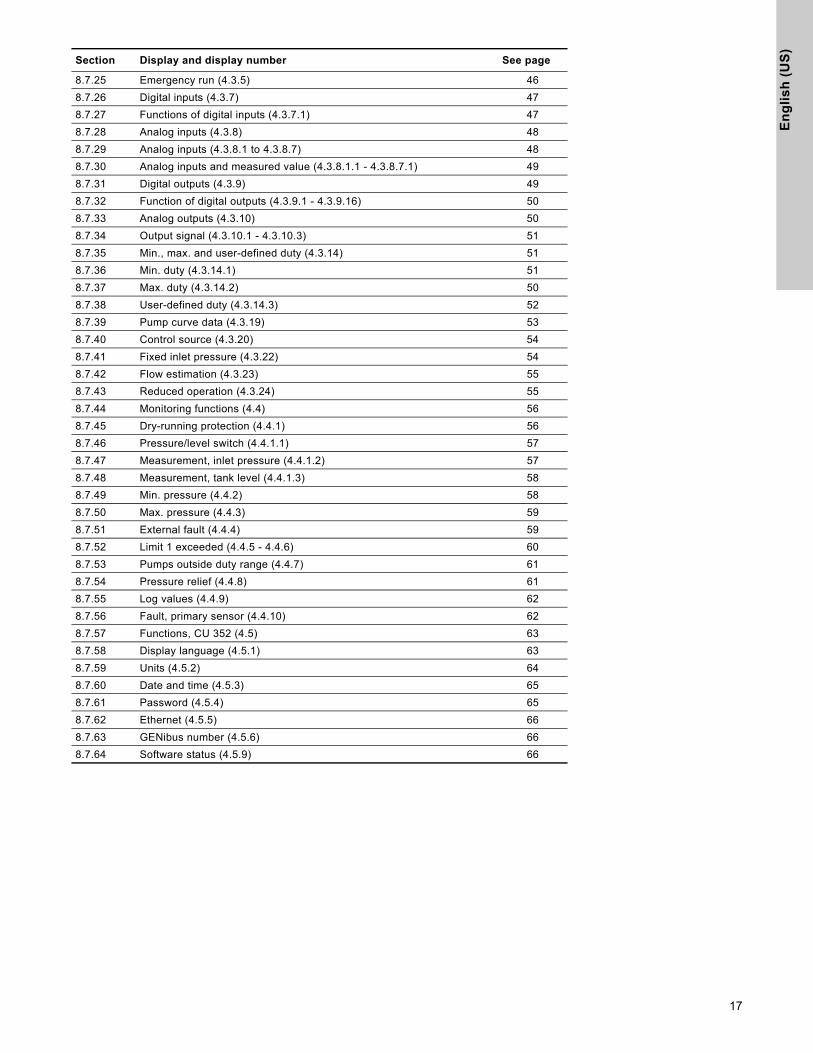
S)
8.7.25 Emergency run (4.3.5) 46
8.7.26 Digital inputs (4.3.7) 47
8.7.27 Functions of digital inputs (4.3.7.1) 47
8.7.28 Analog inputs (4.3.8) 48
8.7.29 Analog inputs (4.3.8.1 to 4.3.8.7) 48
8.7.30 Analog inputs and measured value (4.3.8.1.1 - 4.3.8.7.1) 49
8.7.31 Digital outputs (4.3.9) 49
8.7.32 Function of digital outputs (4.3.9.1 - 4.3.9.16) 50
8.7.33 Analog outputs (4.3.10) 50
8.7.34 Output signal (4.3.10.1 - 4.3.10.3) 51
8.7.35 Min., max. and user-defined duty (4.3.14) 51
8.7.36 Min. duty (4.3.14.1) 51
8.7.37 Max. duty (4.3.14.2) 50
8.7.38 User-defined duty (4.3.14.3) 52
8.7.39 Pump curve data (4.3.19) 53
8.7.40 Control source (4.3.20) 54
8.7.41 Fixed inlet pressure (4.3.22) 54
8.7.42 Flow estimation (4.3.23) 55
8.7.43 Reduced operation (4.3.24) 55
8.7.44 Monitoring functions (4.4) 56
8.7.45 Dry-running protection (4.4.1) 56
8.7.46 Pressure/level switch (4.4.1.1) 57
8.7.47 Measurement, inlet pressure (4.4.1.2) 57
8.7.48 Measurement, tank level (4.4.1.3) 58
8.7.49 Min. pressure (4.4.2) 58
8.7.50 Max. pressure (4.4.3) 59
8.7.51 External fault (4.4.4) 59
8.7.52 Limit 1 exceeded (4.4.5 - 4.4.6) 60
8.7.53 Pumps outside duty range (4.4.7) 61
8.7.54 Pressure relief (4.4.8) 61
8.7.55 Log values (4.4.9) 62
8.7.56 Fault, primary sensor (4.4.10) 62
8.7.57 Functions, CU 352 (4.5) 63
8.7.58 Display language (4.5.1) 63
8.7.59 Units (4.5.2) 64
8.7.60 Date and time (4.5.3) 65
8.7.61 Password (4.5.4) 65
8.7.62 Ethernet (4.5.5) 66
8.7.63 GENibus number (4.5.6) 66
8.7.64 Software status (4.5.9) 66
Section Display and display number See page
17

En
glis
h (U
S)
8.3 Description of functions
The description of functions is based on the four main menus of the CU 352 control unit:
• Status
• Operation
• Alarm
• Settings
The functions apply to all control variants unless otherwise stated.
8.4 Status (1)
The first status display is shown below. This display is shown when the power is switched on, and it appears if the buttons of the control panel remain untouched for 15 minutes.
Fig. 9 Status
Description
No settings can be made in this menu.
The actual value (process value, PV) of the control parameter, usually the discharge pressure, is shown in the upper right corner (G) together with the selected setpoint (SP) (H).
The upper half of the display (A) shows a graphic illustration of the pump system. The selected measuring parameters are shown with sensor symbol and actual value.
In MPC-E systems where the differential pressure across the pumps and pump curve data are known, the display shows the estimated flow rate when the flow rate and speed of the pumps are within a range where it is possible to estimate the flow rate.
≈ : Indicates that the flow rate is an estimated value.
In the middle of the display, an information field (I) will be shown if any of the following events occurs:
• Limited operation due to standby pump
• Proportional-pressure influence active
• External setpoint influence active
• Alternative setpoint active
• Low flow boost active
• Pressure relief active
• Clock program active
• Remote-controlled via Ethernet
• Remote-controlled via GENI (RS-485)
• Limited due to reduced operation
• Stopped due to low flow
The lower display half (B) shows the following:
• the most recent active alarm, if any, and the fault cause with the fault code in brackets
• system status with actual operating mode and control source
• pump status with actual operating mode.
If the fault is related to one of the pumps, the symbols or will also be shown in front of the status line (D) of the pump in question. At the same time, the pump status indicator (E) will change color to either yellow or red as described in the table below. The symbol or will be shown to the right in the top line of the display (F). As long as a fault is present, this symbol will be shown in the top line of all displays.
To open a menu line, select the line with [ ∨ ] or [ ∧ ] and press [ok].
The display makes it possible to open status displays showing the following:
• actual alarms
• system status
• status of each pump.
Description of pump status
8.4.1 Actual alarms (3.1)
Fig. 10 Actual alarms
Description
This display shows active unreset alarms and warnings.
For further information, see sections 8.6.2 Actual alarms (3.1) and 8.6.3 Alarm log (3.2).
NoteNote The estimated flow rate may differ from a measured value.
A
B
C
D
E
F
G
H
I
NoteNote
If a fault has occurred, the warning symbol or alarm symbol will be shown in the line (C) together with the cause and fault code,for instance "Overtemperature (64)".
Pump status indicator Description
Rotating, green Pump running.
Permanently green Pump ready (not running).
Rotating, yellow Warning. Pump running.
Permanently yellow Warning. Pump ready (not running).
Permanently red Alarm. Pump stopped.
18

En
gli
sh
(U
S)
8.4.2 System (1.2)Fig. 11 System
Description
This display shows the operational state of the system. It is possible to go to subdisplays showing details.
The display makes it possible to open displays about the following:
• Operating mode
• Setpoint
• Setpoint influence
• Measured values
• Analog inputs
• Log graph
• Battery status
8.4.3 Operating mode (1.2.1)
Fig. 12 Operating mode
Description
This display shows the operating mode of the system and from where it is controlled.
Operating modes
The system has six operating modes:
1. Normal
– The pumps adapt their performance to the requirement.
2. Max.
– The pumps run at a constant high speed. Normally, all pumps run at maximum speed.
3. User-defined
– The pumps run at a constant speed set by the user. It is usually a performance between "Max." and "Min".
4. Min.
– The pumps run at a constant low speed. Normally, one pump is running at a speed of 70%.
5. Stop
– All pumps have been stopped.
6. Emergency run
– The pumps run according to the setting made in display Emergency run (4.3.5).
The performance required in these operating modes can be set in menu "Settings":
• Max.
• Min.
• User-defined
• Emergency run
See sections 8.7.35 Min., max. and user-defined duty (4.3.14) and 8.7.25 Emergency run (4.3.5).
The actual operating mode can be controlled from four different sources:
• fault
• external signal
• CU 352
• bus
Control source
The system can be set to remote control via an external bus (option). In this case, you must set a setpoint and an operating mode via the bus.
In menu "Settings", you can select whether the CU 352 or the external bus is to be the control source.
The status of this setting is shown in display "Operating mode".
8.4.4 Setpoint (1.2.2)
Fig. 13 Setpoint
Description
This display shows the selected setpoint and whether it comes from the CU 352 or an external bus.
The display also shows all seven possible setpoints from the CU 352 (for closed- and open-loop control). At the same time, the selected setpoint is shown.
As it is a status display, no settings can be made.
Setpoints can be changed in menu "Operation" or "Settings". See section 8.7.3 Alternative setpoints (4.1.2).
19

En
glis
h (U
S)
8.4.5 Setpoint influence (1.2.3)
Fig. 14 Setpoint influence
Description
The selected setpoint can be influenced by an external analog input parameter. The parameter is shown as percentage from 0 to 100% or as a pressure. The influence can only potentially reduce the setpoint as the influence is a percentage multiplied by the setpoint.
Actual setpoint (SP) = selected setpoint x influence (1) x influence (2) x ...
The display shows the parameters influencing the selected setpoint and the percentage or value of influence.
Some of the possible parameters can be set in display External setpoint influence (4.1.3). The parameter "Low flow boost" is set as a start/stop band as a percentage of the setpoint set in display Stop function (4.3.1). The parameter is set as a percentage in display Proportional pressure (4.1.7).
Finally, the resulting actual setpoint (SP) is shown.
8.4.6 Measured values (1.2.4)
Fig. 15 Measured values
Description
This display gives a general status of all measured and calculated parameters. In MPC-E systems with a flowmeter, the specific energy is shown as an average value and actual value (mean value over the last minute). The average value is based on the accumulated flow shown as total volume. The total volume and specific energy average can be reset in this display.
8.4.7 Analog inputs (1.2.5)
Fig. 16 Analog inputs
Description
This display shows an overview of the analog inputs and the measured values of each input. See sections 8.7.28 Analog inputs (4.3.8), 8.7.29 Analog inputs (4.3.8.1 to 4.3.8.7) and 8.7.30 Analog inputs and measured value (4.3.8.1.1 - 4.3.8.7.1).
8.4.8 Log graph (1.2.6)
Fig. 17 Log graph
Description
This display can show logged data stored in the controller. Select log values in display Log values (4.4.9). Various values can be shown, and the time scale can be changed.
Setting via control panel
Status > System > Log graph
1. Set as a percentage:
• Zoom begins at
• Zoom ends at
2. Select values to be shown
NoteNote The lines "Power consumption" and "Energy consumption" are only shown in MPC-E systems.
20
En
gli
sh
(U
S)
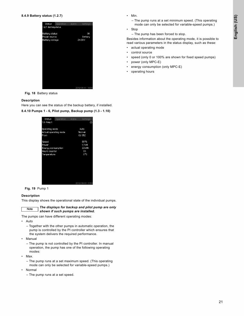
8.4.9 Battery status (1.2.7)Fig. 18 Battery status
Description
Here you can see the status of the backup battery, if installed.
8.4.10 Pumps 1 - 6, Pilot pump, Backup pump (1.3 - 1.10)
Fig. 19 Pump 1
Description
This display shows the operational state of the individual pumps.
The pumps can have different operating modes:
• Auto
– Together with the other pumps in automatic operation, the pump is controlled by the PI controller which ensures that the system delivers the required performance.
• Manual
– The pump is not controlled by the PI controller. In manual operation, the pump has one of the following operating modes:
• Max.
– The pump runs at a set maximum speed. (This operating mode can only be selected for variable-speed pumps.)
• Normal
– The pump runs at a set speed.
• Min.
– The pump runs at a set minimum speed. (This operating mode can only be selected for variable-speed pumps.)
• Stop
– The pump has been forced to stop.
Besides information about the operating mode, it is possible to read various parameters in the status display, such as these:
• actual operating mode
• control source
• speed (only 0 or 100% are shown for fixed speed pumps)
• power (only MPC-E)
• energy consumption (only MPC-E)
• operating hours
NoteNote The displays for backup and pilot pump are only shown if such pumps are installed.
21
En
glis
h (U
S)
8.5 Operation (2)
In this menu, you can set the basic parameters, such as setpoint, operating mode, control mode and individual pump control.
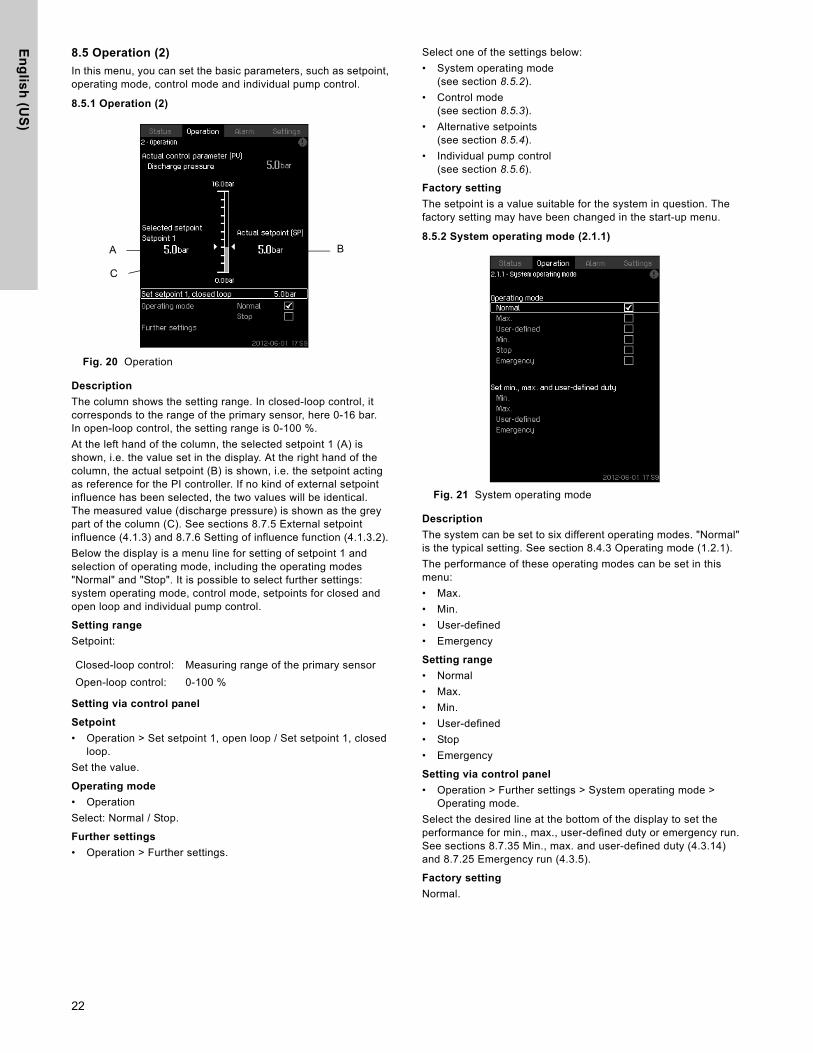
8.5.1 Operation (2)
Fig. 20 Operation
Description
The column shows the setting range. In closed-loop control, it corresponds to the range of the primary sensor, here 0-16 bar.In open-loop control, the setting range is 0-100 %.
At the left hand of the column, the selected setpoint 1 (A) is shown, i.e. the value set in the display. At the right hand of the column, the actual setpoint (B) is shown, i.e. the setpoint acting as reference for the PI controller. If no kind of external setpoint influence has been selected, the two values will be identical. The measured value (discharge pressure) is shown as the grey part of the column (C). See sections 8.7.5 External setpoint influence (4.1.3) and 8.7.6 Setting of influence function (4.1.3.2).
Below the display is a menu line for setting of setpoint 1 and selection of operating mode, including the operating modes "Normal" and "Stop". It is possible to select further settings: system operating mode, control mode, setpoints for closed and open loop and individual pump control.
Setting range
Setpoint:
Setting via control panel
Setpoint
• Operation > Set setpoint 1, open loop / Set setpoint 1, closed loop.
Set the value.
Operating mode
• Operation
Select: Normal / Stop.
Further settings
• Operation > Further settings.
Select one of the settings below:
• System operating mode(see section 8.5.2).
• Control mode(see section 8.5.3).
• Alternative setpoints(see section 8.5.4).
• Individual pump control(see section 8.5.6).
Factory setting
The setpoint is a value suitable for the system in question. The factory setting may have been changed in the start-up menu.
8.5.2 System operating mode (2.1.1)
Fig. 21 System operating mode
Description
The system can be set to six different operating modes. "Normal" is the typical setting. See section 8.4.3 Operating mode (1.2.1).
The performance of these operating modes can be set in this menu:
• Max.
• Min.
• User-defined
• Emergency
Setting range
• Normal
• Max.
• Min.
• User-defined
• Stop
• Emergency
Setting via control panel
• Operation > Further settings > System operating mode > Operating mode.
Select the desired line at the bottom of the display to set the performance for min., max., user-defined duty or emergency run. See sections 8.7.35 Min., max. and user-defined duty (4.3.14) and 8.7.25 Emergency run (4.3.5).
Factory setting
Normal.
Closed-loop control: Measuring range of the primary sensor
Open-loop control: 0-100 %
A
C
B
22

En
gli
sh
(U
S)
8.5.3 Control mode (2.1.2)Fig. 22 Control mode
Description
There are two control modes, namely closed and open loop.
Closed loop
The typical control mode is closed loop where the built-in PI controller ensures that the system reaches and maintains the selected setpoint. The performance is based on the setpoint set for closed loop. See figures 23 and 24.
Fig. 23 Booster system controlled by built-in PI controller (closed loop)
Fig. 24 Regulation curve for closed loop
Setting via control panel
• Operation > Further settings > Control mode > Closed loop.
Set the setpoint. See sections 8.5.4 and 8.5.1.
Open loop
In open-loop control, the pumps run at a fixed speed. The pump speed is calculated from the performance set by the user (0-100%). The pump performance in percentage is proportional with the flow rate.
Open-loop control is usually used when the system is controlled by an external controller which controls the performance via an external signal. The external controller could for instance be a building management system connected to the MPC system. In such cases the MPC is like an actuator. See figures 25 and 26.
Fig. 25 Booster system with external controller (open loop)
Fig. 26 Regulation curve for open loop
Fig. 27 Regulation curve for MPC-E system in open loop
TM
03
22
31
39
05
TM
03
23
90
41
05
P [psi]
Time [sec]
SetpointT
M0
3 2
23
2 3
90
5T
M0
3 2
39
1 3
60
7T
M0
3 9
97
7 4
80
7
05
Input [%] from external controller
Flow rate [gpm]
10050 70.75
25
50
75
100
86.6
Flow rate [gpm]
Input [%] from external controller
Pump 1
Pump 4Pump 3
Flow rate
Pump 2
23

En
glis
h (U
S)
Fig. 28 Regulation curve for MPC-F system in open loop
Fig. 29 Regulation curve for MPC-S system in open loop
Correlating open loop input setpoint percentage with number of pumps in operation. Example: MPC system with (4) pumps
• Setpoint 0% to 5% = All pumps stopped
One pump operation from setpoint from 5% to √
(1-pump/4-pumps) = 50%
• Two pump operation from 50% to √ (2-pump/4-pumps) = 70.7%
• Three pump operation from 70.7% to √ (3-pumps/4-pumps) = 86.6%
• Four pump operation from 86.6% to 100%
• For staging pumps off the cut-out is 2% less then cut-in. Example: staging from 4-pump to 3-pump operation will occur at 84.6% reference signal.
Setting range
These settings must be made in connection with open loop:
• Open loop
• Set setpoint 1, open loop
• External setpoint influence
• Normal
Setting via control panel
Proceed as follows to set an external control source to control the system:
• Operation > Further settings > Control mode
• Select: Open loop
• Select: Stop
1. x 2.
2. Set to 100%: Set setpoint 1, open loop
3. Settings > Primary controller > External setpoint influence > Go to setting of analog input
4. Select analog input and range
5. Select:
• Measured input value Display 4.3.8.1.1 appears
• Select: 0-100% signal
6. .
7. Set the minimum and maximum sensor value.
8. x 2
9. Select:
• Input value to be influenced by
• 0-100% signal
10. .
11. Select: Set the influence function(See also section 8.7.6.)
12. Set the number of points
13. Set: External input value. (Point 1.)
14. Set as a percentage: Reduce setpoint to. (Point 1.)
15. Repeat steps 13 and 14 for all selected points
16. .
17. Set as seconds: Filter time
18. Select: Enabled
19. x 2
20. Select:
• Operation
• Normal
The booster system can now be controlled by an external controller.
Factory setting
Closed-loop control.
TM
03
99
75
48
07
TM
03
99
74
48
07
10050 70.75
25
50
75
100
86.6
Input [%] from external controller
Flow rate [gpm]
Pump 1Pump 2Pump 3
Flow rate
Pump 4
10050 70.75
25
50
75
100
86.6
Flow rate gpm]
Input [%] from external controller
Pump 1
Pump 4Pump 3
Flow rate
Pump 2
24
En
gli
sh
(U
S)
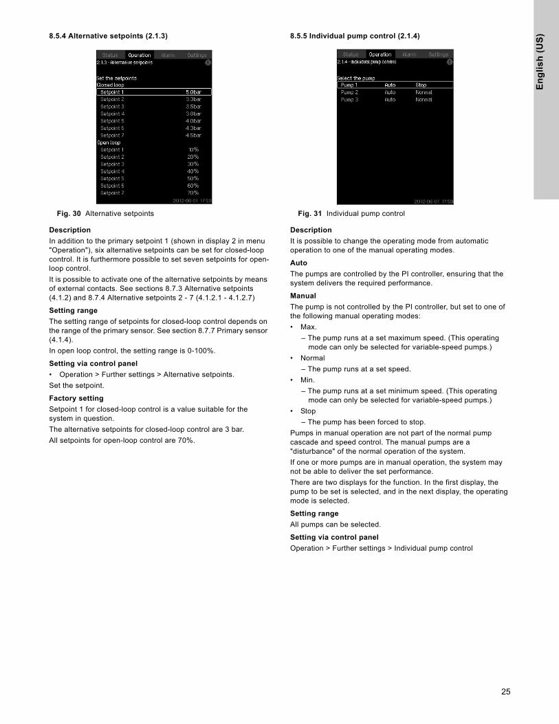
8.5.4 Alternative setpoints (2.1.3)Fig. 30 Alternative setpoints
Description
In addition to the primary setpoint 1 (shown in display 2 in menu "Operation"), six alternative setpoints can be set for closed-loop control. It is furthermore possible to set seven setpoints for open-loop control.
It is possible to activate one of the alternative setpoints by means of external contacts. See sections 8.7.3 Alternative setpoints (4.1.2) and 8.7.4 Alternative setpoints 2 - 7 (4.1.2.1 - 4.1.2.7)
Setting range
The setting range of setpoints for closed-loop control depends on the range of the primary sensor. See section 8.7.7 Primary sensor (4.1.4).
In open loop control, the setting range is 0-100%.
Setting via control panel
• Operation > Further settings > Alternative setpoints.
Set the setpoint.
Factory setting
Setpoint 1 for closed-loop control is a value suitable for the system in question.
The alternative setpoints for closed-loop control are 3 bar.
All setpoints for open-loop control are 70%.
8.5.5 Individual pump control (2.1.4)
Fig. 31 Individual pump control
Description
It is possible to change the operating mode from automatic operation to one of the manual operating modes.
Auto
The pumps are controlled by the PI controller, ensuring that the system delivers the required performance.
Manual
The pump is not controlled by the PI controller, but set to one of the following manual operating modes:
• Max.
– The pump runs at a set maximum speed. (This operating mode can only be selected for variable-speed pumps.)
• Normal
– The pump runs at a set speed.
• Min.
– The pump runs at a set minimum speed. (This operating mode can only be selected for variable-speed pumps.)
• Stop
– The pump has been forced to stop.
Pumps in manual operation are not part of the normal pump cascade and speed control. The manual pumps are a "disturbance" of the normal operation of the system.
If one or more pumps are in manual operation, the system may not be able to deliver the set performance.
There are two displays for the function. In the first display, the pump to be set is selected, and in the next display, the operating mode is selected.
Setting range
All pumps can be selected.
Setting via control panel
Operation > Further settings > Individual pump control
25

En
glis
h (U
S)
8.5.6 Pumps 1 - 6 (2.1.4.1 - 2.1.4.6)
Fig. 32 Pump 1 - 6
Description
This display is shown for the individual pumps and makes it possible to set an operating mode.
Setting range
It is possible to select "Auto" or "Manual" as well as the operating mode of the pump for manual operation - "Max.", "Normal", "Min." or "Stop". For fixed speed pumps only "Normal" or "Stop" can be selected.
Setting via control panel
• Operation > Further settings > Individual pump control
1. Select pump
2. Select resetting: Auto / Manual
3. Manual: Select operating mode.Normal: Set the setpoint.
Factory setting
Auto
8.5.7 Operating mode, pilot pump (2.1.4.7)
Fig. 33 Operating mode, pilot pump
Description
This display is only shown in systems that have been configured with a pilot pump.
It is possible to set the operating mode and setpoint for the pilot pump.
Setting range
Auto
It is possible to select if the pilot pump is to be used as a backup pump. If the pilot pump is selected as a backup pump, it will start if the main pumps are running at 100% speed and still cannot reach or maintain the setpoint.
The setpoint of the pilot pump can either be set to the same value as that of the main pumps by selecting "Use system setpoint" or to another value.
Manual
Max., Normal, Min., Stop
Setting via control panel
• Operation > Further settings > Individual pump control >Pilot pump
Select resetting: Auto / Manual
Auto
1. Select if the pump is also to be used as backup pump(only possible if the system does not already incorporate a backup pump).
2. Select "Use system setpoint" or enter a setpoint.
Manual
1. Select operating mode.
2. Normal: Set the setpoint.
Factory setting
Auto
Use system setpoint
26

En
gli
sh
(U
S)
8.5.8 Operation, backup pump (2.1.4.8)Fig. 34 Operation, backup pump
Description
This display is only shown in systems with a backup pump.
It is possible to set the operating mode, start delay and stop limit for the pump.
The function is only available in pressure-boosting applications.
Setting range
Auto
It is possible to set a start delay. The backup pump will start after the delay set if the main pumps are running at 100% speed and cannot maintain the setpoint.
Two stop parameters can be selected for the backup pump:
• Max. pressure limit
– The backup pump will be stopped if the pressure exceeds the limit set.
• Number of main pumps stopped
– The backup pump will be stopped when the set number of main pumps have stopped.
Manual
Max., Min., Normal, Stop.
Setting via control panel
• Operation > Individual pump control
1. Select backup pump
2. Select: Auto / Manual
Auto
1. Set:
• Start delay
• Stop conditions
Manual
1. Select operating mode
2. Set the setpoint if you select "Normal"
Factory setting
Start delay (auto): 2 minutes
Stop limit: 72 psi
27

En
glis
h (U
S)
8.6 Alarm (3)
This menu gives an overview of alarms and warnings.
It is possible to reset alarms.
8.6.1 Alarm status (3)
Fig. 35 Alarm status
Description
A fault in the system or one of the components monitored can cause an alarm or a warning . Besides the fault signal via the alarm/warning signal relay and the red indicator light on the CU 352, an alarm can also cause a change of operating mode, for instance from "Normal" to "Stop". A warning only causes a fault indication.
The table shows the possible causes of fault together with an alarm code, and whether they result in an alarm or a warning. It also shows to what operating mode the system will change in case of alarm, and whether restarting of the system and resetting of the alarm is manual or automatic.
The table also shows that the reaction to some of the fault causes mentioned can be set in menu "Settings". See sections 8.7.24 Soft pressure build-up (4.3.3) and 8.7.44 Monitoring functions (4.4) to 8.7.54 Pressure relief (4.4.8).
Fa
ult
Wa
rnin
g(
)A
larm
()
Ch
an
ge
of
op
era
tin
g
mo
de
to
Re
se
ttin
g o
f a
larm
Re
sta
rtin
g
Se
t in
me
nu
"S
ett
ing
s"
Ala
rm c
od
e
Water shortage Man/auto
X 206
Water shortage StopMan/auto
X 214
Pressure high StopMan/auto
X 210
Pressure low
Man/auto
X 211Stop
Man/auto
Pressure relief Auto X 219
Alarm, all pumps Stop Auto 203
External fault
Man/auto
X 3Stop
Man/auto
Dissimilar sensor signals
Auto 204
Fault, primary sensor Stop Auto 89
Fault, sensor Auto 88
Communication fault Auto 10
Phase failure Auto 2
Undervoltage, pump Auto7, 40, 42, 73
Overvoltage, pump Auto 32
Overload, pump Auto48, 50,
51, 54
Motor temperature too high
Auto64, 65,
67, 70
Other fault, pump Auto 76, 83
Internal fault, CU 352 Auto83, 157
Internal fault, IO 351 Stop Auto72, 83, 157
VFD not ready Auto 213
Fault, Ethernet Auto231, 232
Limit 1 exceededMan/auto
X 190
Limit 2 exceededMan/auto
X 191
Pressure build-up faultMan/auto
X 215
Pumps outside duty range
Man/auto
X 208
Fault, pilot pump Auto 216
28
En
gli
sh
(U
S)
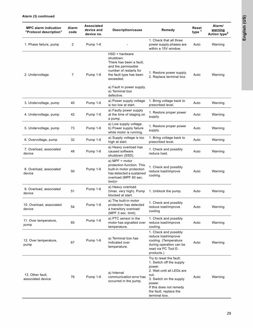
Alarm (3) continuedMPC alarm indication"Protocol description"
Alarmcode
Associateddevice anddevice no.
Description/cause RemedyResettype 1
Alarm/warning
Action type2
1. Phase failure, pump 2 Pump 1-6 -1. Check that all three power supply phases are within a 15V window.
Auto Warning
2. Undervoltage 7 Pump 1-6
HSD = hardware shutdown.There has been a fault, and the permissible number of restarts for the fault type has been exceeded.
a) Fault in power supply.a) Terminal box defective.
1. Restore power supply.2. Replace terminal box.
Auto Warning
3. Undervoltage, pump 40 Pump 1-6a) Power supply voltage is too low at start.
1. Bring voltage back to prescribed level.
Auto Warning
4. Undervoltage, pump 42 Pump 1-6a) Faulty power supply at the time of staging on a pump.
1. Restore proper power supply.
Auto Warning
5. Undervoltage, pump 73 Pump 1-6a) Low supply voltage.b) Power supply failure while motor is running.
1. Restore proper power supply.
Auto Warning
6. Overvoltage, pump 32 Pump 1-6a) Supply voltage is too high at start.
1. Bring voltage back to prescribed level.
Auto Warning
7. Overload, associated device
48 Pump 1-6a) Heavy overload has caused software shutdown (SSD).
1. Check and possibly reduce load.
Auto Warning
8. Overload, associated device
50Pump 1-6
a) MPF = motor protection function. This built-in motor protection has detected a sustained overload (MPF 60 sec. limit)>
1. Check and possibly reduce load/improve cooling.
Auto Warning
9. Overload, associated device
51Pump 1-6
a) Heavy overload (Imax. very high). Pump blocked at start.
1. Unblock the pump. Auto Warning
10. Overload, associated device
54Pump 1-6
a) The built-in motor protection has detected a transitory overload (MPF 3 sec. limit).
1. Check and possibly reduce load/improve cooling
Auto Warning
11. Over temperature, pump
65Pump 1-6
a) PTC sensor in the motor has signalled over temperature.
1. Check and possibly reduce load/improve cooling.
Auto Warning
12. Over temperature, pump
67Pump 1-6
a) Terminal box has indicated over temperature.
1. Check and possibly reduce load/improve cooling. (Temperature during operation can be read via PC Tool E-products.)
Auto Warning
13. Other fault, associated device
76 Pump 1-6a) Internal communication error has occurred in the pump.
Try to reset the fault:1. Switch off the supply power.2. Wait until all LEDs are out.3. Switch on the supply power.If this does not remedy the fault, replace the terminal box.
Auto Warning
29

En
glis
h (U
S)
Alarm (3) continued
MPC alarm indication"Protocol description"
Alarmcode
Associateddevice anddevice no.
Description/cause RemedyResettype 1
Alarm/warning
Action type2
14. Limit 1 exceeded 190Measured parameter
a) The measured parameter has exceeded the limit set.
1. Remove the cause of the fault.
Auto/manual
Alarm/warningStop/
unchanged
15. Limit 2 exceeded 191Measuredparameter
a) The measured parameter has exceeded the limit set.
1. Remove the cause of the fault.
Auto/manual
Alarm/warningStop/
unchanged
16. Pressure relief 219 Systema) The monitored pressure could not be reduced sufficiently.
1. Reduce the pressureto below the limit.
AutoWarning
unchanged
17. Pressure build-up fault 215 Systema) The pressure set cannot be reached within the configured time.
1. Check limit and pipes.Auto/
manual
Alarm/warningStop/
unchanged
18. Pumps outside duty range
208 Systema) The pump is running outside the defined range.
1. Check the system.Auto/
manual
Warningunchanged
19. Pilot pump fault 216 Pilot pump a) Pilot pump fault1. Check wires.2. Check the pump.
Auto Warning
20. Water shortage, level 1*Water shortage, level 1
206
a) The inlet pressure (or the level in the feed tank) is below its programmable warning limit.
AutoWarning
unchanged
21. Water shortage, level 2*Water shortage, level 2
214
a) The inlet pressure (or the level in the feed tank) is below its programmable warning limit.b) The inlet pressure switch detect water shortage.
1. Check the actual and the corresponding settings.2. Check the sensor/switch, wiring and input according to the wiring diagram.3. Check the sensor/switch.
Auto/manual
AlarmStop
Warningunchanged
22. Discharge pressure high. *Pressure above max. pressure
210System
a) The system pressure is above the programmable high-pressure alarm limit.
Auto/manual
AlarmFast stop (over rule min. seq.
time)
23. Discharge pressure low*Pressure below min.pressure
211
a) The system pressure is below the programmable low-pressure alarm limit.
Auto/manual
24. All pumps in alarm*All pumps in alarm
203
a) All pumps, set to Auto, are stopped on account of pump alarm.
Troubleshoot according to the alarm message/code:1. System2. Use fault finding documentation for the type of pump installed.
AutoAlarmStop
b) Pumps are not indicating alarm
Check the Genibus wires eg. connection, polarization.
25. External fault signal*External fault signal
003a) External fault digital input activated.
1. Check the external signal source.2. Check the digital input according to the wiring diagram
Auto/manual
Alarm/WarningStop/
unchanged
26. Inconsistency between sensors*Inconsistency between sensors
204
Primary sensor and/or
redundant sensor
a) Primary feedback sensor value (pressure) is inconsistent with redundant feedback sensor value.
1. Check the wiring and input according to the wiring diagram.2. Check the sensor output according to the measured value.
AutoWarning
unchanged
30

En
gli
sh
(U
S)
Alarm (3) continued1) Reset type is either fixed as "Auto acknowledge" (Auto) or can be programmed to be Auto or manual acknowledge (Auto/Man)*.2) Programmable action types:
-Go to operating mode "Stop" (no delay (<0.5 s) between pump disconnections).-Go to operating mode "Min."-Go to operating mode "User-defined."-Go to operating mode "Max."-Set pumps in source mode "Local." - No action (warning only)
MPC alarm indication"Protocol description"
Alarmcode
Associateddevice anddevice no.
Description/cause RemedyResettype 1
Alarm/warning
Action type2
27. Primary sensor*Closed loop feedbacksensor signal fault
089 Primary sensor
a) A fault in the sensor assigned to the feed back control is detected.
b) Error in the settings of the sensor which is assigned to the regulator.
1. Check the wiring and input according to the wiring diagram.
2. Check the sensor output according to the measured value.
AutoAlarmStop
28. Sensor fault*General (measurement)sensor signal fault
088CU 351
IO 351 asIO module
a) The signal (ex. 4-20 mA) from one of the analog sensors is outside the selected signal range.
1. Check the wiring and input according to the wiring diagram.
2. Check the sensor output according to the measured value.
WarningUnchanged
29. CU 351 internal fault *Real time clock out of order
157a) The real-time clock in CU 351 is out of order.
Replace the CU 351
30. Ethernet fault*Ethernet: No addressfrom DHCP server
231a) No address from DHCP server
1. Communication error.
2. Please contact the system integrator or network administrator.
31. Ethernet fault*Ethernet: Auto disableddue to misuse
232 CU 351a) Auto-disabled due to misuse
32. FLASH parameter verification error*FLASH parameter verification error
083a) Verification error in CU 351 FLASH memory
Replace the CU 351
33. IO 351 internal fault*Hardware fault type 2
080 IO 351
a) IO 351 pump module hardware fault
b) IO 351 I/O module hardware fault
See current alarms and identify the faulty IO 351 module from the alarm message and replace the module.
34. VFD not ready*VFD not ready
213Pump 1-6
IO 351
a) The VFD signal relay do not release the VFD for operation
1. Check for VFD alarm2. Check the wiring and input according to the wiring diagram.
AutoWarning
Unchanged
35. Communication fault *Pump communication fault
010Pump 1-6
IO 351
a) No GeniBuscommunication with a device connected to CU 351
See actual alarms and identify the faulty device from the alarm message.1. Check power supply2. Check GeniBus cable connection3. Check, with R100, that the device GeniBus no. is correct.
36. Device alarmsFrom
devicePump 1-6 a) The device is in alarm
See actual alarms and identify the faulty device from the alarm message.1. Fault find according to the service instruction for the device.
31

En
glis
h (U
S)
8.6.2 Actual alarms (3.1)
Fig. 36 Actual alarms
Description
This submenu shows the following:
• Warnings caused by faults that still exist.
• Warnings caused by faults that have disappeared, but the warning requires manual resetting.
• Alarms caused by faults that still exist.
• Alarms caused by faults that have disappeared, but the alarm requires manual resetting.
All warnings and alarms with automatic resetting are automatically removed from the menu when the fault has disappeared.
Alarms requiring manual resetting can be reset in this display by pressing [ok]. An alarm cannot be reset until the fault has disappeared.
For every warning or alarm, the following will be shown:
• Whether it is a warning or an alarm .
• Where the fault occurred: System, Pump 1, Pump 2, ...
• In case of input-related faults, the input will be shown.
• The cause of the fault and the alarm code in brackets, e.g. "Water shortage (214)".
• When the fault occurred: Date and time.
• When the fault disappeared: Date and time. If the fault still exists, date and time will be shown as --...--.
The most recent warning/alarm is shown at the top of the display.
8.6.3 Alarm log (3.2)
The alarm log can store up to 24 warnings and alarms.
Fig. 37 Alarm log
Description
Here warnings and alarms are shown.
For every warning or alarm, the following will be shown:
• Whether it is a warning or an alarm .
• Where the fault occurred. System, Pump 1, Pump 2, ...
• In case of input-related faults, the input will be shown.
• The cause of the fault and the alarm code in brackets, e.g. "Water shortage (214)".
• When the fault occurred: Date and time.
• When the fault disappeared: Date and time. If the fault still exists, date and time will be shown as --...--.
The most recent warning/alarm is shown at the top of the display.
8.6.4 Service contact information (3.3)
Fig. 38 Service contact information
Description
This display shows the contact information of the installer if entered during commissioning.
32

En
gli
sh
(U
S)
8.7 Settings (4)Fig. 39 Settings
In this menu, you can set the following functions:
• Primary controllerPI controller, Alternative setpoints, External setpoint influence, Primary sensor, Clock program, Proportional pressure, S-system configuration, Setpoint ramp.
• Pump cascade controlMin. time between start/stop, Max. number of starts/hour, Number of standby pumps, Forced pump changeover, Pump test run, Pump stop attempt, Pump start and stop speed, Min. performance, Compensation for pump start-up time.
• Secondary functionsStop function, Soft pressure build-up, Digital inputs, Analog inputs, Digital outputs, Analog outputs, Emergency run, Min., max, and user-defined duty, Pump curve data, Control source, Fixed inlet pressure, Flow estimation, Reduced operation.
• Monitoring functionsDry-running protection, Min. pressure, Max. pressure, External fault, Limit 1 exceeded, Limit 2 exceeded, Pumps outside duty range, Pressure relief, Log values, Fault, primary sensor.
• Functions, CU 352Display language, Units, Date and time, Password, Ethernet, GENibus number, Software status. The service language, English, can be selected for service purposes. All these functions are usually set correctly when the system is switched on.
8.7.1 Primary controller (4.1)
Fig. 40 Primary controller
Description
It is possible to set the functions related to the primary controller. It is only necessary to make settings in this menu if the functionality is to be expanded with for instance alternative setpoints, external setpoint influence, clock program or proportional pressure.
The following menus can be selected:
• PI controller
• Alternative setpoints
• External setpoint influence
• Primary sensor
• Clock program
• Proportional pressure
• S-system configuration
33

En
glis
h (U
S)
8.7.2 PI controller (4.1.1)
Fig. 41 PI controller
Description
The system includes a standard PI controller which ensures that the pressure is stable and corresponds to the setpoint.
It is possible to adjust the PI controller if a faster or slower reaction to changes of consumption is required.
A faster reaction is obtained if Kp is increased and Ti is reduced.
A slower reaction is obtained if Kp is reduced and Ti is increased.
Setting range
• Gain Kp: -30 to 30.Note: For inverse control, set Kp to a negative value.
• Integral time Ti: 0.1 to 3600 seconds.
Setting via control panel
• Settings
• Primary controller
• PI controller
1. Set the gain (Kp) and integral time (Ti).Note: Usually it is not necessary to adjust Kp.
Factory setting
• Kp: 0.5
• Ti: 1 second.
8.7.3 Alternative setpoints (4.1.2)
Fig. 42 Alternative setpoints
Description
This function makes it possible to select up to six setpoints (2 to 7) as alternatives to the primary setpoint (1). The primary setpoint (1) is set in the "Operation" menu.Every alternative setpoint can be addressed manually to a separate digital input (DI). When the contact of the input is closed, the alternative setpoint applies.
If more than one alternative setpoint has been selected, and they are activated at the same time, the CU 352 will select the setpoint with the lowest number.
Setting range
• Six setpoints, No 2 to 7.
Factory setting
No alternative setpoints have been selected.
34

En
gli
sh
(U
S)
8.7.4 Alternative setpoints 2 - 7 (4.1.2.1 - 4.1.2.7)Fig. 43 Alternative setpoints 2 - 7
For each alternative setpoint, select the digital input to activate the setpoint.
It is possible to set a setpoint for closed loop and for open loop.
Setting via control panel
• Settings > Primary controller > Alternative setpoints
1. Select alternative setpoint.
2. Select: alternative setpointDisplay Digital inputs (4.3.7) appears.
3. Set the input.
4. .
5. Select the menu line of the setpoint (closed or open loop).
6. Set the setpoint.Set both setpoints if the system is to be controlled both in open and closed loop.
Factory setting
No alternative setpoints have been set.
8.7.5 External setpoint influence (4.1.3)
Fig. 44 External setpoint influence
Description
This function makes it possible to adapt the setpoint by letting measuring parameters influence the setpoint. Typically an analog signal from a flow or temperature transmitter, or a similar transmitter.
As an example, the setpoint can be adapted to parameters that can influence the discharge pressure or temperature of the system. The parameters which influence the performance of the system are shown as a percentage from 0 to 100%. They can only reduce the setpoint, as the influence as a percentage is multiplied with the setpoint:
Actual setpoint (SP) = selected setpoint x influence (1) x influence (2) x ...
The influence values can be set individually.
A low-pass filter ensures smoothing of the measured value which influences the setpoint. This results in stable setpoint changes.
Setting range
• 0 - 100% signal
• Inlet pressure
• Discharge pressure
• External pressure
• Diff. pressure, external
• Diff. pressure, pump
• Flow rate
• Tank level, discharge side
• Tank level, suction side
• Return-pipe temp., external
• Flow-pipe temperature
• Return-pipe temperature
• Differential temperature
• Ambient temperature
• Differential temperature
35

En
glis
h (U
S)
Setting via control panel
• Settings > Primary controller > External setpoint influence > Input value to be influenced by. A list of available parameters appears.
1. Select the parameter which is to influence the setpoint.
2. .
3. Set the influence function (See section 8.7.6.)
4. Set the number of points
5. Set: External input value. (Point 1.)
6. Set as a percentage: Reduce setpoint to. (Point 1.)
7. Repeat steps 4 to 6 for all desired parameters
8. .
9. Set as seconds: Filter time
10. Select: Enabled
Factory setting
The function is disabled.
8.7.6 Setting of influence function (4.1.3.2)
Fig. 45 Setting of influence function
Description
It is possible to select the relation between the measuring parameter which is to influence the setpoint and the desired influence as a percentage.
The relation is set by entering values in a table with maximum eight points by means of the control panel.
Example:
Fig. 46 Relation between setpoint influence and flow rate
The control unit draws straight lines between the points.A horizontal line is drawn from the minimum value of the relevant sensor (0 gpm in the example) to the first point. This is also the case from the last point to the sensor's maximum value (example 500 gpm).
Setting range
Two to eight points can be selected. Each point contains the relation between the value of the parameter which is to influence the setpoint and the influence of the value.
TM
03
16
91
08
15
Flow rate [gpm]
Setpoint influence [%]
36
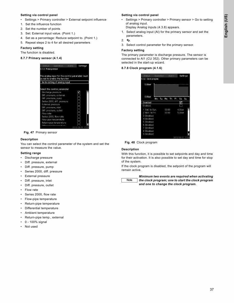
En
gli
sh
(U
S)
Setting via control panel• Settings > Primary controller > External setpoint influence
1. Set the influence function
2. Set the number of points
3. Set: External input value. (Point 1.)
4. Set as a percentage: Reduce setpoint to. (Point 1.)
5. Repeat steps 2 to 4 for all desired parameters
Factory setting
The function is disabled.
8.7.7 Primary sensor (4.1.4)
Fig. 47 Primary sensor
Description
You can select the control parameter of the system and set the sensor to measure the value.
Setting range
• Discharge pressure
• Diff. pressure, external
• Diff. pressure, pump
• Series 2000, diff. pressure
• External pressure
• Diff. pressure, inlet
• Diff. pressure, outlet
• Flow rate
• Series 2000, flow rate
• Flow-pipe temperature
• Return-pipe temperature
• Differential temperature
• Ambient temperature
• Return-pipe temp., external
• 0 - 100% signal
• Not used
Setting via control panel
• Settings > Primary controller > Primary sensor > Go to setting of analog input.Display Analog inputs (4.3.8) appears.
1. Select analog input (AI) for the primary sensor and set the parameters.
2. .
3. Select control parameter for the primary sensor.
Factory setting
The primary parameter is discharge pressure. The sensor is connected to AI1 (CU 352). Other primary parameters can be selected in the start-up wizard.
8.7.8 Clock program (4.1.6)
Fig. 48 Clock program
Description
With this function, it is possible to set setpoints and day and time for their activation. It is also possible to set day and time for stop of the system.
If the clock program is disabled, the setpoint of the program will remain active.
NoteNoteMinimum two events are required when activating the clock program; one to start the clock program and one to change the clock program.
37

En
glis
h (U
S)
Setting range
• Activation and setting of event.
Fig. 49 Event 1
Setting via control panel
• Settings > Primary controller > Clock program
1. Enable the function
2. Select and enable one of the ten events
3. Select: "Normal" or "Stop" (Skip step 4 if you select "Stop".)
4. Set: Setpoint, closed loop
5. Set: Time, Hours, Minutes
6. Select the day of week on which the settings are to be activated
7. Select: Enabled
8. Repeat steps 2 to 7 if several events are to be enabled.Note: Up to ten events can be set.
9. .
10. Select: Enabled
Factory setting
The function is disabled.
8.7.9 Proportional pressure (4.1.7)
Fig. 50 Proportional pressure
Description
The function can only be enabled in pressure-controlled systems and automatically adapts the setpoint to the actual flow rate to compensate for flow-dependent dynamic losses. As many systems are designed with extra flow capacity, the estimated
maximum flow rate (Qpmax) can be entered manually. In systems with CR pumps, the pump curves can be used to calculate the maxium flow rate at the selected setpoint. A filter factor can be set to prevent fluctuation.
The adaptation can be linear or square. See fig. 50.
Fig. 51 Proportional pressure
The function has these purposes:
• to compensate for pressure losses• to reduce the energy consumption• to increase the comfort for the user
Setting range
• Selection of control mode• Influence at 0 flow• Estimated flow rate• Filter factor
Setting via control panel
• Settings > Primary controller > Proportional pressure1. Select: Enabled2. Select: • Adaptation• Linear / Square3. Set: Influence at 0 flow4. Set: Filter factor5. Select: Use pump curve / Enter value6. Set "Qpmax" if you select "Enter value"
TM
05
30
05
08
12
Pos. Description
APressure at 0 flow. Starting point of proportional-pressure control (influence at 0 flow = x % of setpoint)
B QpmaxC Setpoint
H
C
A
B
Q
Starting point of proportional pressure control (Influence at 0 flow = x% of Hset)
38

En
gli
sh
(U
S)
Factory settingThe function is disabled.
8.7.10 S-sytem configuration (4.1.8)
Fig. 52 S-system configuration
Description
The function makes it possible to invert the control of fixed speed pumps (MPC-S). That is to set whether pumps are to be started or stopped depending on the actual value.
A start/stop band must be set in order to use this function. See fig. 53.
Normal
A pump is stopped when the value becomes higher than Hset + start/stop band. And a pump is started when the value becomes lower than Hset. See fig. 53.
Inverse
A pump is started when the value becomes higher than Hset + start/stop band. And a pump is stopped when the value becomes lower than Hset. See fig. 53.
Fig. 53 Normal and inverse control
Setting range
• Selection of configuration (normal or inverse)
• Start/stop band
Setting via control panel
• Settings > Primary controller > S-system configuration
1. Select: Normal / Inverse
2. Set: Start/stop band
Factory setting
Normal
8.7.11 Setpoint ramp (4.1.9)
Fig. 54 Setpoint ramp
Description
When this function is enabled, setpoint changes will be affected by the setpoint ramp, and the setpoint will change gradually over a period of time.
"Proportional pressure" or "Setpoint influence" will not be affected by this function.
Setting range
The function can be enabled and change per minute can be set.
Setting via control panel
• Settings > Primary controller > Setpoint ramp
1. Select: Enabled2. Set: Change per minute
Factory setting
The function is disabled.
8.7.12 Pump cascade control (4.2)
Fig. 55 Pump cascade control
It is possible to set the functions connected to pump cascade control.
The following menus can be selected:
• Min. time between start/stop• Max. number of starts/hour• Standby pumps• Forced pump changeover• Pump test run• Pilot pump• Pump stop attempt• Pump start and stop speed• Min. performance• Compensation for pump start-up time
TM
03
92
05
36
07
- T
M0
3 9
20
5 3
60
7
Start/stop band
Hset
Time [sec]
H [psi]
Pump stops
Pump starts
Normal
Start/stop band
Hset
Time [sec]
H [psi]
Pump starts
Pump stops
Inverse
39

En
glis
h (U
S)
8.7.13 Min. time between start/stop (4.2.1)
Fig. 56 Min. time between start/stop
Description
This function ensures a delay between the starting/stopping of one pump and the starting/stopping of another pump.
The purpose is to prevent hunting when pumps start and stop continuously.
Setting range
From 1 to 3600 seconds.
Setting via control panel
Settings > Pump cascade control > Min. time between start/stop.
Factory setting
The setting is done in the start-up wizard and depends on the application.
8.7.14 Max. number of starts/hour (4.2.1)
Fig. 57 Max. number of starts/hour
Description
This function limits the number of pump starts and stops per hour for the complete system. It reduces noise emission and improves the comfort of systems with fixed speed pumps.
Each time a pump starts or stops, the CU 352 calculates when the next pump is allowed to start/stop in order not to exceed the permissible number of starts per hour.
The function always allows pumps to be started to meet the requirement, but pump stops will be delayed, if needed, in order not to exceed the permissible number of starts per hour.
The time between pump starts must be between the minimum time between start/stop, see section 8.7.13, and 3600/n, n being the set number of starts per hour.
Setting range
1 to 1000 starts per hour.
Setting via control panel
• Settings > Pump cascade control > Max. number of starts/hour
1. Set:
• Min. time between start/stop
• Max. number of starts/hour
Factory setting
8.7.15 Standby pumps (4.2.3)
Fig. 58 Standby pumps
Description
This function makes it possible to limit the maximum performance of the system, by selecting one or more pumps as standby pumps.
If a three-pump system has one standby pump, maximum two pumps are allowed to be in operation at a time.
If one of the two pumps in operation has a fault and has stopped, the standby pump will be started. The performance of the system is thus not reduced.
The status as standby pump alternates between all pumps.
Setting range
The number of possible standby pumps in a system is equal to the total number of pumps in the system minus 1.
Setting via control panel
• Settings > Pump cascade control > Standby pumps
• Set: Set the number of standby pumps
Factory setting
The number of standby pumps is set to 0, i.e. function is disabled.
MPC-E: 200 starts per hour
Other variants: 100 starts per hour
NoteNote This function has no influence on Stop function (4.3.1).
40

En
gli
sh
(U
S)
8.7.16 Forced pump changeover (4.2.4)Fig. 59 Forced pump changeover
Description
This function ensures that the pumps run for the same number of operating hours.
In certain applications, the requirement remains constant for long periods and does not require all pumps to run. In such situations, pump changeover does not take place naturally, and forced pump changeover may thus be required.
Once every 24 hours, the CU 352 checks if any pump running has a larger number of operating hours than pumps that are stopped. If this is the case, the pump will be stopped and replaced by a pump with a lower number of operating hours.
Setting range
The function can be enabled/disabled. The hour of the day at which the changeover is to take place can be set.
Setting via control panel
• Settings > Pump cascade control > Forced pump changeover
1. Select: Enabled
2. Set: Time of day for changeover
3. Select interval for pump changeover.
Factory setting
The function is enabled. The time is set to 03:00.
8.7.17 Pump test run (4.2.5)
Fig. 60 Pump test run
Description
This function is primarily used in situations where the forced pump changeover is disabled, and/or if the system is set to operating mode "Stop", for instance in a period when the system is not needed. In such situations, it is important to test the pumps regularly.
Advantages of this function:
• Pumps do not seize up during a long standstill due to deposits from the pumped liquid.
• The pumped liquid does not decay in the pump.
• Trapped air is removed from the pump.
The pumps start automatically one by one and run for five seconds.
Setting range
• Time of day
• Day of week
• Include pilot pump
• Include backup pump
Setting via control panel
• Settings > Pump cascade control > Pump test run
1. Select interval
2. Set:
• Time of day
• Minutes
3. Select the day of week if you select "Once a week"
4. If system is configured with a pilot or a backup pump, select "include pilot pump" or "Include backup pump"
Factory setting
The function is disabled.
NoteNote
Pumps in operating mode "Manual" are not included in the test run. If there is an alarm, the test run will not be carried out.
If the backup pump is included in the test run, the system pressure will be high when the pump is started.
41

En
glis
h (U
S)
8.7.18 Pump stop attempt (4.2.7)
Fig. 61 Pump stop attempt
Description
The function makes it possible to set automatic stop attempts of a pump when several pumps are running. It ensures that the optimum number of pumps is always running, in terms of energy consumption. See 8.7.19 Pump start and stop speed (4.2.8). At the same time, the purpose is to avoid disturbances in connection with automatic stop of pumps.
Stop attempts can either take place with a fixed interval set under "Interval between stop attempts" or by self-learning. If self-learning is selected, the interval between stop attempts will be increased if repeated attempts to stop the pump fail.
Setting via control panel
• Settings > Pump cascade control > Pump stop attempt
1. Select: Self-learning / Fixed interval
2. Set "Interval between stop attempts" if you select "Fixed interval".
3. Select: Enabled
Factory setting
The function is enabled, and "Self-learning" is selected.
8.7.19 Pump start and stop speed (4.2.8)
Description
The function controls the starting and stopping of pumps.There are two options:
1. Use calculated speedThis function ensures that the optimum number of pumps is always running at a desired duty point, in terms of energy consumption. The CU 352 calculates the required number of pumps and their speed. This requires that the differential pressure of the pump is measured by a differential-pressure sensor or separate pressure sensors on the inlet and discharge side. If calculated speed has been selected, the CU 352 will ignore the percentages set.
2. Use fixed speedThe pumps are started and stopped at speeds set by the user.
1. Use calculated speed
Fig. 62 Use calculated speed
Setting via control panel
• Settings > Pump cascade control > Pump start and stop speed > Use calculated speed
2. Use fixed speed
Fig. 63 Use fixed speed
42

En
gli
sh
(U
S)
Setting via control panel• Settings > Pump cascade control > Pump start and stop speed
• Select: Use fixed speed
• Set: Start next pump at this speed > 1 -> 2
1. Set the speed as percentage
2. Set the other pumps in the same way
3. Select: Instant pump stop at > 1 -> 0
4. Set the speed as percentage
5. Set the other pumps in the same way
Factory setting
The function is set to calculated speed.
8.7.20 Min. performance (4.2.9)
Fig. 64 Min. performance
Description
This function ensures circulation in a system. Note that the stop function, if enabled, can influence this function. See section 8.7.23 Stop function (4.3.1). Examples:
• If 0 pumps have been selected, the stop function can stop the pump if there is no or a very small consumption.
• If pumps have been selected, the stop function will not be active.
Setting via control panel
• Settings > Pump cascade control > Min. performance
1. Set:
• Number of pumps
• Speed
Factory setting
The number of pumps is set to 0. The speed in closed loop is set to 25%.
8.7.21 Compensation for pump start-up time (4.2.10)
Fig. 65 Compensation for pump start-up time
Description
The function is used for MPC-F systems only.
The purpose is to avoid disturbances when a fixed speed pump with fixed speed is started. The function compensates for the time it takes a fixed speed pump to reach its full performance after start. The start-up time of the fixed speed pump must be known.
Setting via control panel
• Settings > Pump cascade control > Compensation for pump start-up time
• Set: Pump start-up time
Factory setting
The start-up time is set to 0 seconds.
43
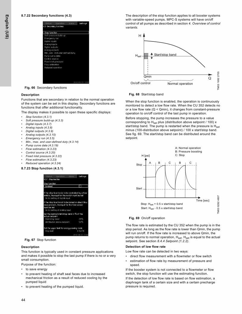
En
glis
h (U
S)
8.7.22 Secondary functions (4.3)
Fig. 66 Secondary functions
Description
Functions that are secondary in relation to the normal operation of the system can be set in this display. Secondary functions are functions that offer additional functionality.
The display makes it possible to open these specific displays:
• Stop function (4.3.1)• Soft pressure build-up (4.3.3)• Digital inputs (4.3.7)• Analog inputs (4.3.8)• Digital outputs (4.3.9)• Analog outputs (4.3.10)• Emergency run (4.3.5)• Min., max. and user-defined duty (4.3.14)• Pump curve data (4.3.19)• Flow estimation (4.3.23)• Control source (4.3.20)• Fixed inlet pressure (4.3.22)• Flow estimation (4.3.23)• Reduced operation (4.3.24)
8.7.23 Stop function (4.3.1)
Fig. 67 Stop function
Description
This function is typically used in constant pressure applications and makes it possible to stop the last pump if there is no or a very small consumption.
Purpose of the function:
• to save energy
• to prevent heating of shaft seal faces due to increased mechanical friction as a result of reduced cooling by the pumped liquid
• to prevent heating of the pumped liquid.
The description of the stop function applies to all booster systems with variable-speed pumps. MPC-S systems will have on/off control of all pumps as described in section 4. Overview of control variants.
Fig. 68 Start/stop band
When the stop function is enabled, the operation is continuously monitored to detect a low flow rate. When the CU 352 detects no or a low flow rate (Q < Qmin), it changes from constant-pressure operation to on/off control of the last pump in operation.
Before stopping, the pump increases the pressure to a value corresponding to Hset plus (distribution above setpoint / 100) x start/stop band. The pump is restarted when the pressure is Hset minus (100-distribution above setpoint) / 100 x start/stop band. See fig. 69. The start/stop band can be distributed around the setpoint.
Fig. 69 On/off operation
The flow rate is estimated by the CU 352 when the pump is in the stop period. As long as the flow rate is lower than Qmin, the pump will run on/off. If the flow rate is increased to above Qmin, the pump returns to normal operation, Hset. Hset is equal to the actual setpoint. See section 8.4.4 Setpoint (1.2.2).
Detection of low flow rate
Low flow rate can be detected in two ways:
• direct flow measurement with a flowmeter or flow switch
• estimation of flow rate by measurement of pressure and speed.
If the booster system is not connected to a flowmeter or flow switch, the stop function will use the estimating function.
If the detection of low flow rate is based on flow estimation, a diaphragm tank of a certain size and with a certain precharge pressure is required.
TM
03
16
92
27
05
TM
03
92
92
48
07
H
Q
Hset
Qmin
Start/stop band
On/off control Normal operation
Stop: Hset + 0.5 x start/stop band
Start: Hset - 0.5 x start/stop band
Stop
Start
H [psi]
Time [sec]
A B C B C
A: Normal operationB: Pressure boostingC: Stop
44

En
gli
sh
(U
S)
Diaphragm tank sizePrecharge pressure
Hydro MPC-E and -F: 0.7 x setpointHydro MPC-S: 0.9 x setpoint
During each flow estimation (every 2 minutes), the estimating function will disturb the discharge pressure by ± 10% of the setpoint. If this disturbance is not acceptable, the stop function must be based on direct flow measurement with a flowmeter or flow switch.
The minimum flow rate can be set, i.e. the flow rate at which the booster system changes to on/off control of the last pump in operation.
If both a flowmeter and a flow switch are connected, the changeover to on/off control will be determined by the unit first indicating low flow rate.
Setting range
Setting via control panel
System without flow switch or flowmeter
• Settings > Secondary functions > Stop function
• Select: Enabled
1. Set: Start/stop band
2. Select: Go to setting of flow stop parameters.The display below appears.
Fig. 70 Stop parameters
3. Select one of the stop parameters. If you select "Customized settings", you must set the parameters shown in fig. 71. See the examples below.
Fig. 71 Customized settings
Example 1: Increasing the stop limit, Qmin (high flow limit)
• Increase the delta pressure for gradient• Reduce the delta time for gradient (pump stopped)• Reduce the delta time for gradient (pump running)• Increase speed reduction
Example 2: Reducing the stop limit, Qmin (low flow limit)
• Reduce the delta pressure for gradient• Increase the delta time for gradient (pump stopped)• Increase the delta time for gradient (pump running)• Reduce speed reduction
System with flow switch
Make the following additional settings:
1. Select: Go to setting of digital input. Display Digital inputs (4.3.7) appears
2. Select the digital input where the flow switch is connected
3. Select: Flow switch
4. .
System with flowmeter
Make the following additional settings:
1. Select: Go to setting of analog inputDisplay Analog inputs (4.3.8) appears
2. Select the analog input where the flowmeter is connected.
3. Select: Flow rate
4. x 2.
5. Set: Stop limit
Pump typeRecommended diaphragm tank size [gallons]
-E -F -S
CR(E) 3 4.4 4.4 20CR(E) 5 4.4 4.4 34CR(E) 10 10.3 10.3 62CR(E) 15 34 34 211CR(E) 20 34 34 211CR(E) 32 44 44 317CR(E) 45 86 86 528CR(E) 64 132 132 1056CR(E) 90 132 132 1056CR(E) 120 132 132 1056CR(E) 150 132 132 1056
Start/stop band: 5-30 %
Min. flow rate:
2-50 % of the rated flow rate (Qnom) of one of the pumps. (Can only be set if direct flow measurement by means of flowmeter has been selected.)
Distribution above setpoint:
0-100 %.
NoteNote Rule of thumb: Speed reduction = 2 x delta pressure for gradient.
Example of increased stop limit
Parameter Value
Delta pressure for gradient 6%Delta time for gradient (pump stopped) 1.5 sec.Delta time for gradient (pump running) 2.0 sec.Speed reduction 10%
Example of reduced flow limit
Parameter Value
Delta pressure for gradient 3%Delta time for gradient (pump stopped) 15.0 sec.Delta time for gradient (pump running) 25.0 sec.Speed reduction 6%
NoteNote The stop limit depends on the tank size.
NoteNote An open contact indicates low flow.
45
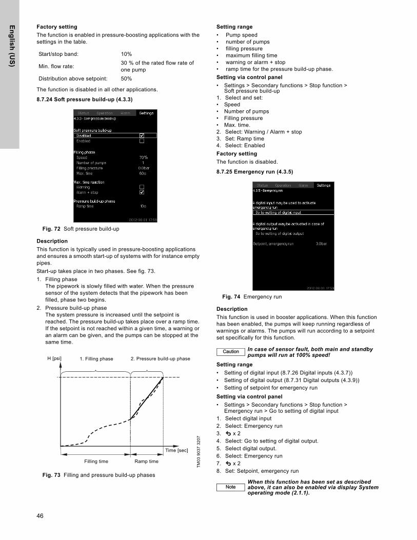
En
glis
h (U
S)
Factory setting
The function is enabled in pressure-boosting applications with the settings in the table.
The function is disabled in all other applications.
8.7.24 Soft pressure build-up (4.3.3)
Fig. 72 Soft pressure build-up
Description
This function is typically used in pressure-boosting applications and ensures a smooth start-up of systems with for instance empty pipes.
Start-up takes place in two phases. See fig. 73.
1. Filling phaseThe pipework is slowly filled with water. When the pressure sensor of the system detects that the pipework has been filled, phase two begins.
2. Pressure build-up phaseThe system pressure is increased until the setpoint is reached. The pressure build-up takes place over a ramp time. If the setpoint is not reached within a given time, a warning or an alarm can be given, and the pumps can be stopped at the same time.
Fig. 73 Filling and pressure build-up phases
Setting range
• Pump speed• number of pumps• filling pressure• maximum filling time• warning or alarm + stop• ramp time for the pressure build-up phase.
Setting via control panel
• Settings > Secondary functions > Stop function >Soft pressure build-up
1. Select and set: • Speed• Number of pumps• Filling pressure• Max. time.2. Select: Warning / Alarm + stop3. Set: Ramp time4. Select: Enabled
Factory setting
The function is disabled.
8.7.25 Emergency run (4.3.5)
Fig. 74 Emergency run
Description
This function is used in booster applications. When this function has been enabled, the pumps will keep running regardless of warnings or alarms. The pumps will run according to a setpoint set specifically for this function.
Setting range
• Setting of digital input (8.7.26 Digital inputs (4.3.7))• Setting of digital output (8.7.31 Digital outputs (4.3.9))• Setting of setpoint for emergency run
Setting via control panel
• Settings > Secondary functions > Stop function >Emergency run > Go to setting of digital input
1. Select digital input2. Select: Emergency run3. x 24. Select: Go to setting of digital output.5. Select digital output.6. Select: Emergency run7. x 28. Set: Setpoint, emergency run
Start/stop band: 10%
Min. flow rate:30 % of the rated flow rate of one pump
Distribution above setpoint: 50%
TM
03
90
37
32
07
1. Filling phase 2. Pressure build-up phaseH [psi]
Filling time Ramp time
Time [sec]
Caution In case of sensor fault, both main and standby pumps will run at 100% speed!
NoteNoteWhen this function has been set as described above, it can also be enabled via display System operating mode (2.1.1).
46
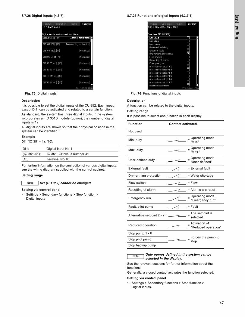
En
gli
sh
(U
S)
8.7.26 Digital inputs (4.3.7)Fig. 75 Digital inputs
Description
It is possible to set the digital inputs of the CU 352. Each input, except DI1, can be activated and related to a certain function.
As standard, the system has three digital inputs. If the system incorporates an IO 351B module (option), the number of digital inputs is 12.
All digital inputs are shown so that their physical position in the system can be identified.
Example
DI1 (IO 351-41), [10]:
For further information on the connection of various digital inputs, see the wiring diagram supplied with the control cabinet.
Setting range
Setting via control panel
• Settings > Secondary functions > Stop function >Digital inputs
8.7.27 Functions of digital inputs (4.3.7.1)
Fig. 76 Functions of digital inputs
Description
A function can be related to the digital inputs.
Setting range
It is possible to select one function in each display:
See the relevant sections for further information about the functions.
Generally, a closed contact activates the function selected.
Setting via control panel
• Settings > Secondary functions > Stop function >Digital inputs.
DI1: Digital input No 1
(IO 351-41): IO 351, GENIbus number 41
[10]: Terminal No 10
NoteNote DI1 (CU 352) cannot be changed.
Function Contact activated
Not used
Min. duty =Operating mode "Min."
Max. duty =Operating mode "Max."
User-defined duty =Operating mode "User-defined"
External fault = External fault
Dry-running protection = Water shortage
Flow switch = Flow
Resetting of alarm = Alarms are reset
Emergency run =Operating mode "Emergency run"
Fault, pilot pump = Fault
Alternative setpoint 2 - 7 =The setpoint is selected
Reduced operation =Activation of "Reduced operation"
Stop pump 1 - 6
=Forces the pump to stop
Stop pilot pump
Stop backup pump
NoteNote Only pumps defined in the system can be selected in the display.
47

En
glis
h (U
S)
Factory setting
8.7.28 Analog inputs (4.3.8)
Fig. 77 Analog inputs
Description
Each analog input can be activated and related to a certain function.
As standard, the system has three analog inputs. If the system incorporates an IO 351B module (option), the number of analog inputs is 5.
All analog inputs are shown so that their physical position in the system can be identified. A redundant primary sensor can be fitted as backup for the primary sensor in order to increase reliability and prevent stop of operation.
Example
AI1 (CU 352) [51]:
Setting via control panel
• Settings > Secondary functions > Stop function >Analog inputs
8.7.29 Analog inputs (4.3.8.1 to 4.3.8.7)
Fig. 78 Analog inputs
Description
Analog inputs can be set. Each display is divided into three parts:
• Setting of input signal, for instance 4-20 mA
• Measured input value, for instance discharge pressure
• Measuring range of the sensor/signal transmitter, for instance 0-16 bar
Setting range
It is possible to set the following parameters in each display:
• Not used
• Range of input signal, 0-20 mA, 4-20 mA, 0-10 V
• Measured input value
• Sensor range
Setting via control panel
• Settings > Secondary functions > Stop function >Analog inputs.
Factory setting
Digital input Function
DI1 (CU 352) [10]External start/stop. Open contact = stop.Note: Input No 1 cannot be changed.
DI2 (CU 352) [12]Monitoring of water shortage (dry-running protection). Open contact = water shortage (if the system is supplied with this option).
NoteNote Monitoring of water shortage requires a pressure or level switch connected to the system.
NoteNote If two sensors are to be redundant, each must have a separate analog input.
AI1: Analog input No 1
(CU 352): CU 352
[51]: Terminal No 51
NoteNote
If an analog input is deactivated, the display will only show the top part, i.e. the setting of the analog input.If the input is activated, the middle part, "Measured input value," will be shown.This makes it possible to relate a function to the analog input in another display. When the analog input has been related to a function, the CU 352 will return to the display for setting of analog inputs.
Analog input Function
AI1 (CU 352) [51] Discharge pressure
48

En
gli
sh
(U
S)
8.7.30 Analog inputs and measured value(4.3.8.1.1 - 4.3.8.7.1)
Fig. 79 Analog inputs and measured value
Description
A function can be related to the individual analog inputs.
Setting range
It is possible to select one function per analog input.
• Not used
• 0 - 100% signal
• Inlet pressure
• Discharge pressure
• External pressure
• Diff. pressure, pump
• Flow rate 1 - 3
• Tank level, discharge side
• Tank level, suction side
• System pressure
• Diff. pressure, external
• Tank precharge pressure
• Diff. pressure, inlet
• Diff. pressure, outlet
• Return-pipe temp., external
• Flow-pipe temperature
• Return-pipe temperature
• Differential temperature
• Ambient temperature
• Power, pump 1 - 6
• Power, VFD
Setting via control panel
• Settings > Secondary functions > Stop function >Analog inputs
1. Select analog input
2. Select: Measured input valueDisplay 4.3.8.1.1 appears.
3. Select input.
4. .
5. Set the minimum and maximum sensor value.
8.7.31 Digital outputs (4.3.9)
Fig. 80 Digital outputs
Description
Each digital output can be activated and related to a certain function.
As standard, the system has two digital outputs.
If the system incorporates an IO 351B module (option), the number of digital outputs is 9.
All digital outputs are shown so that their physical position in the system can be identified.
Example
DO1 (IO 351-41) [71]:
For further information on the connection of various digital outputs, see the wiring diagram supplied with the CU 352.
NoteNoteIf more flow rates are used, the flow rate measured and shown will be the sum of defined flow rates.
TM
03
23
33
46
07
DO1 Digital output No 1
(IO 351-41) IO 351B, GENIbus number 41
[71] Terminal No 71
49

En
glis
h (U
S)
8.7.32 Function of digital outputs (4.3.9.1 - 4.3.9.16)
Fig. 81 Function of digital outputs
Description
A function can be related to the individual outputs.
Setting range
It is possible to select one function in each display:
• No function
• Operation, system
• Alarm, system
• Warning, system
• Ready, system
• Water shortage
• Min. pressure
• Max. pressure
• Emergency run
• Operation, pilot pump
• Operation, backup pump
• Pressure relief valve
• Pump outside duty range
• Operation, pump(s)
• Operation, pump 1 - 6
• Alarm, pump 1
• Alarm, limit 1 exceeded
• Warning, limit 1 exceeded
• Alarm, limit 2 exceeded
• Warning, limit 2 exceeded
• Reduced operation
Setting via control panel
• Settings > Secondary functions > Stop function >Digital outputs
Factory setting
8.7.33 Analog outputs (4.3.10)
Fig. 82 Analog outputs
Description
The CU 352 does not have analog outputs as standard, but the system can be fitted with an IO 351B module with three analog outputs.
Setting via control panel
• Settings > Secondary functions > Stop function >Analog outputs
Digital output Function
DO1 (CU 352) [71] Alarm, system
DO2 (CU 352) [74] Operation, system
NoteNote This display will only appear if an IO 351B module is installed.
50

En
gli
sh
(U
S)
8.7.34 Output signal (4.3.10.1 - 4.3.10.3)Fig. 83 Output signal
Description
You can select the parameters below.
Setting range
• 0 - 100% signal• Inlet pressure• Discharge pressure• External pressure• Diff. pressure, pump• Tank level, discharge side• Tank level, suction side• System pressure• Diff. pressure, external• Tank precharge pressure• Diff. pressure, inlet• Diff. pressure, outlet• Return-pipe temp., external• Flow-pipe temperature• Return-pipe temperature• Differential temperature• Ambient temperature• Differential pressure 2 - 3• System power• Power, pump 1 - 6• Power, pilot pump• Power, backup pump• Power, VFD• Speed, pump 1 - 6• Current, pump 1 - 6• Current, pilot pump• Current, backup pump
Setting via control panel
• Settings > Secondary functions > Stop function >Analog outputs
1. Select analog output and range
2. Select: ParameterDisplay 4.3.10.2 appears
3. Select output
4. .
5. Set: Signal range
8.7.35 Min., max. and user-defined duty (4.3.14)
Fig. 84 Min., max. and user-defined duty
Description
This function makes it possible to let the pumps run in open loop at a set performance.
Setting range
The CU 352 makes it possible to change between three operating modes:
1. Min. duty (4.3.14.1)
2. Max. duty (4.3.14.2)
3. User-defined duty (4.3.14.3)
8.7.36 Min. duty (4.3.14.1)
Fig. 85 Min. duty
Description
In all systems, apart from MPC-S systems, minimum duty is only possible for variable-speed pumps. In MPC-S systems, only the number of pumps running at 100 % speed can be set.
Setting range
• Number of pumps in operation.
• Speed as percentage (25 to 100 %) for variable-speed pumps.
Setting via control panel
• Settings > Secondary functions > Stop function > Min., max. and user-defined duty > Min. duty
Select and set:
• Number of pumps in operation, min. duty
• Speed
Factory setting
NoteNoteFor each of these operating modes, the number of operating pumps and the pump performance (speed) can be set.
Number of pumps in operation during min. duty: 1
Speed as percentage for variable-speed pumps: 70
51

En
glis
h (U
S)
8.7.37 Max. duty (4.3.14.2)
Fig. 86 Max. duty
Description
The function makes it possible for a set number of pumps to run at maximum performance when the function is enabled.
Setting range
You can set the number of pumps to run in the operating mode "Max." All pumps run at 100% speed.
Setting via control panel
• Settings > Secondary functions > Stop function > Min., max. and user-defined duty > Max. duty
Select and set: Number of pumps in operation at 100% speed, max. duty.
Factory setting
8.7.38 User-defined duty (4.3.14.3)
Fig. 87 User-defined duty
Description
You can set a user-defined performance, typically a performance between min. and max. duty.
The function makes it possible to set a pump performance by selecting the number of pumps to run and the speed of variable-speed pumps.
This function primarily selects the variable-speed pumps. If the number of selected pumps exceeds the number of variable-speed pumps, fixed speed pumps are started too.
Setting range
• Number of pumps in operation.
• Speed as percentage for variable-speed pumps.Note: In systems with only variable-speed pumps, the speed can be set between 25 and 100%; in systems with both variable-speed pumps and fixed speed pumps the speed can be set between 70 and 100%.
Setting via control panel
• Settings > Secondary functions > Stop function >Min., max. and user-defined duty > User-defined duty
Select and set:
• Number of pumps in operation, user-defined duty
• Speed
Factory setting
The function is disabled as the following has been set:
Number of pumps in operation during max. duty:
All pumps(except standby pumps)
Number of pumps in operation during user-defined duty: 0
52

En
gli
sh
(U
S)
8.7.39 Pump curve data (4.3.19)Fig. 88 Pump curve data
Description
The CU 352 has a number of functions using pump data information:
The data are read by means of the pump performance curves which can be found in WebCAPS on Grundfos’ homepage, www.grundfos.com. See the examples in fig. 89 to 92.
If WebCAPS is not accessible, try to bring a pump into the three duty points:
• Power, Q0, 100% speed• Power, Q0, 50% speed• Rated power PnomRead the power values in displays 1.3 to 1.8, depending on the pump. See section 8.4.10 Pumps 1 - 6, Pilot pump, Backup pump (1.3 - 1.10).
Fig. 89 Reading of Qnom, Hnom, Hmax & Qmax (WebCAPS)
Fig. 90 Reading of power, Q0, 100 % speed (WebCAPS)
Fig. 91 Reading of power, Q0, 50 % speed (WebCAPS)
Fig. 92 Reading of rated power Pnom (WebCAPS)
• Rated flow rate Qnom [gpm]
• Rated head Hnom [ft]
• Max. head Hmax [ft]
• Max. flow rate Qmax [gpm]
• Power, Q0, 100% speed [kW]
• Power Q0, 50% speed [kW]
• Rated power Pnom [kW]
NoteNote
Grundfos can supply hydraulic data for CR and CRE pumps where GSC files can be downloaded to the CU 352.All other pump types require manual entering of hydraulic pump data.
NoteNote
The electrical data, "Power, Q0, 100% speed" and "Power, Q0, 50% speed" must be entered manually for all pump types, including CR and CRE.For Grundfos E-pumps, the data of input power (P1) must be entered.
TM
03
99
93
48
07
Rated duty point
Hnom
Qnom Qmax
Hmax
TM
03
99
94
48
07
TM
03
99
95
48
07
TM
03
99
96
48
07
NoteNoteQnom and Hnom are the rated duty point of the pumps and usually the duty point with the highest efficiency.
Power, Q0, 100 % speed
Duty point, Q0, 100 % speed
Power, Q0, 50 % speed
Duty point, Q0, 50 % speed
Duty point, rated power Pnom
Rated power Pnom
53

En
glis
h (U
S)
Setting via control panel
• Settings > Secondary functions > Stop function Settings > Secondary functions > Stop function > Pump curve data
4. Select and set:
• Rated flow rate Qnom
• Rated head Hnom
• Max. head Hmax
• Max. flow rate Qmax
• Power, Q0, 100% speed
• Power Q0, 50% speed
• Rated power Pnom
8.7.40 Control source (4.3.20)
Fig. 93 Control source
Description
The system can be remote-controlled via an external bus connection (option). See section 8.8.2 GENIbus. For further information, see section 8.8 Data communication.
The control source, CU 352 or the external bus connection, can be selected.
Setting via control panel
• Settings > Secondary functions > Stop function >Control source
Factory setting
The control source is the CU 352.
8.7.41 Fixed inlet pressure (4.3.22)
Fig. 94 Fixed inlet pressure
Description
This function is only used when no inlet-pressure sensor is fitted in the system and the inlet pressure is fixed and known.
If the booster system has a fixed inlet pressure, it can be entered in this display so that the CU 352 can optimize the performance and control of the system.
Setting range
A fixed inlet pressure can be set, and the function can be enabled/disabled.
Setting via control panel
• Settings > Secondary functions > Stop function > Fixed inlet pressure
• Select: Enabled / Disabled
• Set: Fixed inlet pressure
Factory setting
The function is disabled.
54

En
gli
sh
(U
S)
8.7.42 Flow estimation (4.3.23)Fig. 95 Flow estimation
Description
As described in section 8.7.39 Pump curve data (4.3.19), the CU 352 can optimize operation according to performance curves and motor data. In this display, you can select the curve types which the CU 352 will use for the optimization if they are available.
At large flow rates, there may be a considerable head loss between the pump discharge flange and the pressure sensor. The loss is caused by non-return valves and pipe bends. To improve the flow estimation of the system, it is necessary to compensate for the difference between the measured and the actual differential pressure across the pump. This is done by entering the head loss in non-return valves and pipe bends at the rated flow rate of one pump.
Setting range
• 2nd order QH polynomial
• 5th order QH polynomial
• Power polynomial, QP
• Head loss
Setting via control panel
• Settings > Secondary functions > Stop function >Flow estimation
Factory setting
All polynomials are selected.
8.7.43 Reduced operation (4.3.24)
Fig. 96 Reduced operation
Description
This function makes it possible to limit the number of pumps in operation, or for MPC-E systems, to limit power consumption. The limit is activated by a digital input.
Setting range
• Setting of digital input (8.7.26 Digital inputs (4.3.7))
• Setting of digital output (8.7.31 Digital outputs (4.3.9))
• Maximum number of pumps in operation
• Maximum power consumption
Setting via control panel
• Settings > Secondary functions > Stop function >Reduced operation > Go to setting of digital input
1. Select digital input.
2. Select: Reduced operation
3. x 2.
4. Select: Go to setting of digital output
5. Select digital output.
6. Select: Reduced operation
7. x 2.
8. Set: Number of pumps in operation / Power consumption
Factory setting
No digital input is selected (disabled).
NoteNoteIt is possible to select several curve types, as the CU 352 makes a priority based on the data available.
55
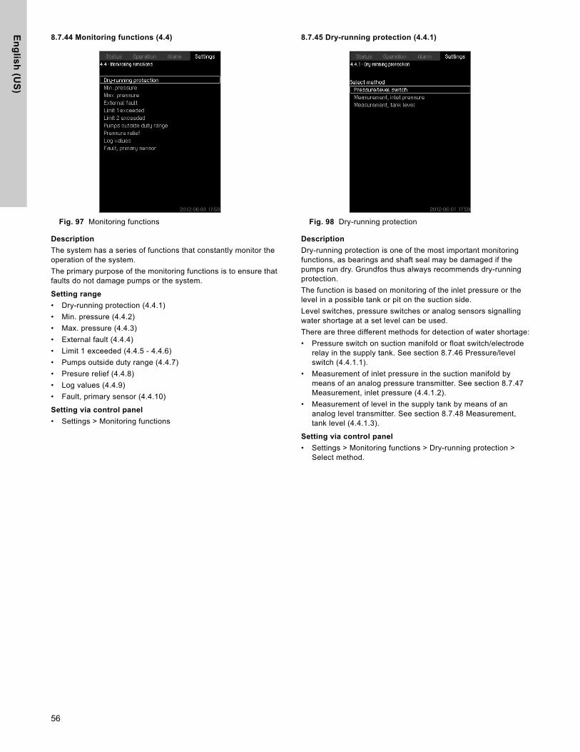
En
glis
h (U
S)
8.7.44 Monitoring functions (4.4)
Fig. 97 Monitoring functions
Description
The system has a series of functions that constantly monitor the operation of the system.
The primary purpose of the monitoring functions is to ensure that faults do not damage pumps or the system.
Setting range
• Dry-running protection (4.4.1)
• Min. pressure (4.4.2)
• Max. pressure (4.4.3)
• External fault (4.4.4)
• Limit 1 exceeded (4.4.5 - 4.4.6)
• Pumps outside duty range (4.4.7)
• Presure relief (4.4.8)
• Log values (4.4.9)
• Fault, primary sensor (4.4.10)
Setting via control panel
• Settings > Monitoring functions
8.7.45 Dry-running protection (4.4.1)
Fig. 98 Dry-running protection
Description
Dry-running protection is one of the most important monitoring functions, as bearings and shaft seal may be damaged if the pumps run dry. Grundfos thus always recommends dry-running protection.
The function is based on monitoring of the inlet pressure or the level in a possible tank or pit on the suction side.
Level switches, pressure switches or analog sensors signalling water shortage at a set level can be used.
There are three different methods for detection of water shortage:
• Pressure switch on suction manifold or float switch/electrode relay in the supply tank. See section 8.7.46 Pressure/level switch (4.4.1.1).
• Measurement of inlet pressure in the suction manifold by means of an analog pressure transmitter. See section 8.7.47 Measurement, inlet pressure (4.4.1.2).
• Measurement of level in the supply tank by means of an analog level transmitter. See section 8.7.48 Measurement, tank level (4.4.1.3).
Setting via control panel
• Settings > Monitoring functions > Dry-running protection > Select method.
56

En
gli
sh
(U
S)
8.7.46 Pressure/level switch (4.4.1.1)Fig. 99 Pressure/level switch
Description
This function is primarily used in booster applications. Dry-running protection can take place by means of a pressure switch on the suction manifold or a level switch in a tank on the suction side.
When the contact is open, the CU 352 will register water shortage after a time delay of approximately five seconds. It is possible to set whether the indication is to be just a warning or an alarm stopping the pumps.
Restarting and resetting of alarms can be set to be automatic or manual.
Setting range
• Selection of digital input for the function
• Reaction in case of water shortage: Alarm + stop
• Restarting: Manual / Auto
Setting via control panel
• Settings > Monitoring functions > Dry-running protection > Pressure/level switch > Go to setting of digital input Display Digital inputs (4.3.7) appears.
1. Set the input to dry-running protection.
2. .
3. Select:
• Warning / Alarm + stop
• Manual / Auto
Factory setting
The setting is done in the start-up wizard and depends on the application.
8.7.47 Measurement, inlet pressure (4.4.1.2)
Fig. 100 Measurement, inlet pressure
Description
Dry-running protection can take place by means of a pressure transmitter measuring the inlet pressure.
It is possible to set two levels:
• Warning
• Alarm + stop
Restarting and resetting of alarms can be set to be automatic or manual.
Setting range
• Selection of analog input for the function
• Inlet pressure level for warning
• Inlet pressure level for alarm + stop
• Restarting: Auto / Manual
Setting via control panel
• Settings > Monitoring functions > Dry-running protection > Measurement, inlet pressure > Go to setting of analog inputDisplay Analog inputs (4.3.8) appears.
1. Select: Inlet pressure
2. .
3. Select: Enabled
4. Select and set the level:
• Warning
• Alarm + stop
5. Select resetting: Auto / Manual
Factory setting
The setting is done in the start-up wizard and depends on the application.
NoteNoteIf one of the levels is not required, the level value must be the minimum value of the inlet-pressure transmitter. This disables the function.
57

En
glis
h (U
S)
8.7.48 Measurement, tank level (4.4.1.3)
Fig. 101 Mesurement, tank level
Description
Dry-running protection can take place by means of a level transmitter measuring the level in a tank on the suction side.
It is possible to set two levels:
• Warning
• Alarm + stop
Restarting and resetting of alarms can be set to be automatic or manual.
Setting range
• Selection of analog input for the function
• Tank level for warning
• Tank level for alarm + stop
• Restarting: Manual or automatic
Setting via control panel
• Settings > Monitoring functions > Dry-running protection > Measurement, tank level > Go to setting of analog input.Display Analog inputs (4.3.8) appears
1. Set the input to "Tank level, suction side"
2. .
3. Select: Enabled
4. Select and set the level:
• Warning
• Alarm + stop
5. Select resetting: Auto / Manual
Factory setting
The function is disabled.
8.7.49 Min. pressure (4.4.2)
Fig. 102 Min. pressure
Description
The discharge pressure will be monitored if the application is pressure boosting. In all other applications, the system pressure will be monitored. The CU 352 will react if the pressure becomes lower than a set minimum level for an adjustable time.
The minimum pressure can be monitored if a fault indication is required in situations where the discharge pressure becomes lower than the set minimum pressure.
It is possible to set whether the indication is to be just a warning or an alarm stopping the pumps. This may be desirable if the system is used for an irrigation system where a very low discharge pressure may be due to pipe fracture and thus an extraordinarily high consumption and a very low counter-pressure. In such situations, it is desirable that the system stops and indicates alarm. This situation will require manual resetting of alarms.
It is possible to set a start-up delay ensuring that the system can build up pressure before the function is enabled. It is also possible to set a time delay, i.e. for how long time the discharge pressure may be lower than the set minimum pressure before the alarm is activated.
Setting range
• Minimum pressure level within the range of the primary sensor
• Activation of stop when the pressure falls below the minimum pressure
• Time delay of function at start-up
• Time delay of function during operation
Setting via control panel
• Settings > Monitoring functions > Min. pressure > Enabled
1. Select and set: Min. pressure
2. Select: Alarm + stop at min. pressure
3. Set:
• Time delay of function at start-up
• Time delay of function during operation
Factory setting
The function is disabled.
58

En
gli
sh
(U
S)
8.7.50 Max. pressure (4.4.3)Fig. 103 Max. pressure
Description
The discharge pressure will be monitored if the application is pressure boosting. In all other applications, the system pressure will be monitored. The CU 352 will react if the pressure becomes higher than a set maximum level.
In certain installations, a too high discharge pressure may cause damage. It may therefore be necessary to stop all pumps for a short period if the pressure is too high.
It is possible to set whether the system is to restart automatically after the pressure has dropped below the maximum level, or if the system must be reset manually. Restarting will be delayed by an adjustable time. See section 8.7.13 Min. time between start/stop (4.2.1).
Setting range
• Maximum pressure level within the range of the primary sensor
• Manual or automatic restarting
Setting via control panel
• Settings > Monitoring functions > Max. pressure > Enabled
4. Set: Max. pressure
5. Select resetting: Auto / Manual
Factory setting
The function is disabled
8.7.51 External fault (4.4.4)
Fig. 104 External fault
Description
The function is used when the CU 352 is to be able to receive a fault signal from an external contact. In case of external fault, the CU 352 indicates warning or alarm. In case of alarm, the system changes to another manual operating mode, for instance "Stop."
Setting range
• Selection of digital input for the function
• Setting of time delay from closing of the contact until the CU 352 reacts
• Reaction in case of external fault: Warning or alarm and change of operating mode
• Restarting after alarm: Manual or automatic
Setting via control panel
• Settings > Monitoring functions > External fault > Go to setting of digital inputDisplay Digital inputs (4.3.7) appears
6. Set the input to "External fault"
7. .
8. Set: Time delay, fault indication
9. If only a warning is required in case of external fault, select "Warning"If the system is to give alarm and change operating mode in case of external fault, select operating mode "Manual" or "Auto"
Factory setting
The function is disabled. If the function is enabled, the following values have been set from factory:
• Time delay: 5 seconds
• Operating mode in case of alarm: Stop
• Restarting: Manual
59

En
glis
h (U
S)
8.7.52 Limit 1 exceeded (4.4.5 - 4.4.6)
Fig. 105 Limit 1 exceeded
Description
With this function, the CU 352 can monitor set limits of analog values. It will react if the values exceed the limits. Each limit can be set as a maximum or minimum value. For each of the monitored values, a warning limit and an alarm limit must be defined.
The function makes it possible to monitor two different locations in a pump system at the same time. For instance the pressure at a consumer and the pump discharge pressure. This ensures that the discharge pressure does not reach a critical value.
If the value exceeds the warning limit, a warning is given. If the value exceeds the alarm limit, the pumps will be stopped.
A delay can be set between the detection of an exceeded limit and the activation of a warning or an alarm. A delay can also be set for resetting a warning or an alarm.
A warning can be reset automatically or manually.
It is possible to set whether the system is to restart automatically after an alarm, or if the alarm must be reset manually. Restarting can be delayed by an adjustable time. It is also possible to set a start-up delay ensuring that the system reaches a steady state before the function becomes active.
Setting range
• Selection of analog input for the function
• input value to be monitored
• limit type (min./max.)
• warning limit
• alarm limit.
Setting via control panel
• Settings > Monitoring functions > Limit 1 exceeded /Limit 2 exceeded > Go to setting of analog input
1. Select analog input
2. Select: Input value to be monitored Display 4.3.8.1.1 appears
3. Select input
4. .
5. Set the minimum and maximum sensor value
6. x 2.
7. Select: Input value to be monitored
8. Select input
9. .
10. Select:
• Min. limit / Max. limit
• Set delays
11. .
12. Select:
• Set warning limit
• Enabled
13. Set limit
14. Select resetting: Auto / Manual
15. .
16. Select:
• Set alarm limit
• Enabled
17. Set limit
18. Select resetting: Auto / Manual
19. .
20. Select: Enabled
Factory setting
The function is disabled.
NoteNoteAnalog inputs must be correctly set before the function is enabled. See section 8.7.28 Analog inputs (4.3.8).
60

En
gli
sh
(U
S)
8.7.53 Pumps outside duty range (4.4.7)Fig. 106 Pumps outside duty range
Description
The function gives a warning if the duty point of the pumps moves outside the defined range. For instance, if the inlet pressure becomes lower than a minimum permissible value, thus causing a risk of cavitation for some pump types.
The warning is given with a set time delay. It is possible to set whether the warning is to be reset automatically or manually when the duty point comes within the defined duty range. You can also set a relay output to be activated when the warning is given, and to be deactivated when the warning is reset.
This function requires that the discharge pressure and the inlet pressure (either measured or configured) or the differential pressure of the pumps is monitored, and that CU 352 contains valid pump data from either a GSC file or from manual input. See section 8.7.39 Pump curve data (4.3.19).
Setting range
• Setting of manual or automatic resetting
• Setting of warning delay
Setting via control panel
• Settings > Monitoring functions > Pumps outside duty range > Manual / Auto > Set warning delay
Factory setting
The function is disabled.
8.7.54 Pressure relief (4.4.8)
Fig. 107 Pressure relief
Description
The purpose of the function is to reduce the pressure in the pipework by opening a solenoid valve if it exceeds a set limit.If the pressure is not reduced within a given time, the solenoid valve will be closed, and a warning can be given.
Fig. 108 Pressure relief
Setting range
• Setting of digital output• Setting of pressure to be monitored• Setting of valve opening pressure• Setting of band for valve opening pressure• Setting of warning or alarm
Setting via control panel
• Settings > Monitoring functions > Pressure relief >Go to setting of digital output
1. Select digital output2. Select: Pressure relief3. x 24. Select:• Pressure to be monitored• Discharge pressure, System pressure / External pressure5. .6. Select and set:• Valve opening pressure• Band, valve opening pressure7. Select: Warning > Disabled / Enabled8. Set: Delay(Only to be set if warning has been enabled.)9. Select: Enabled
TM
03
92
06
36
07
4
Band
Warning delay
Valve openingpressure
Valve opening pressure minus band
P [psi]
Time [sec]
1: Solenoid valve opens.
2: Solenoid valve closes.
3: Solenoid valve opens.
4: Warning is activated.
5: Solenoid valve closes, and warning is reset.
5321
61
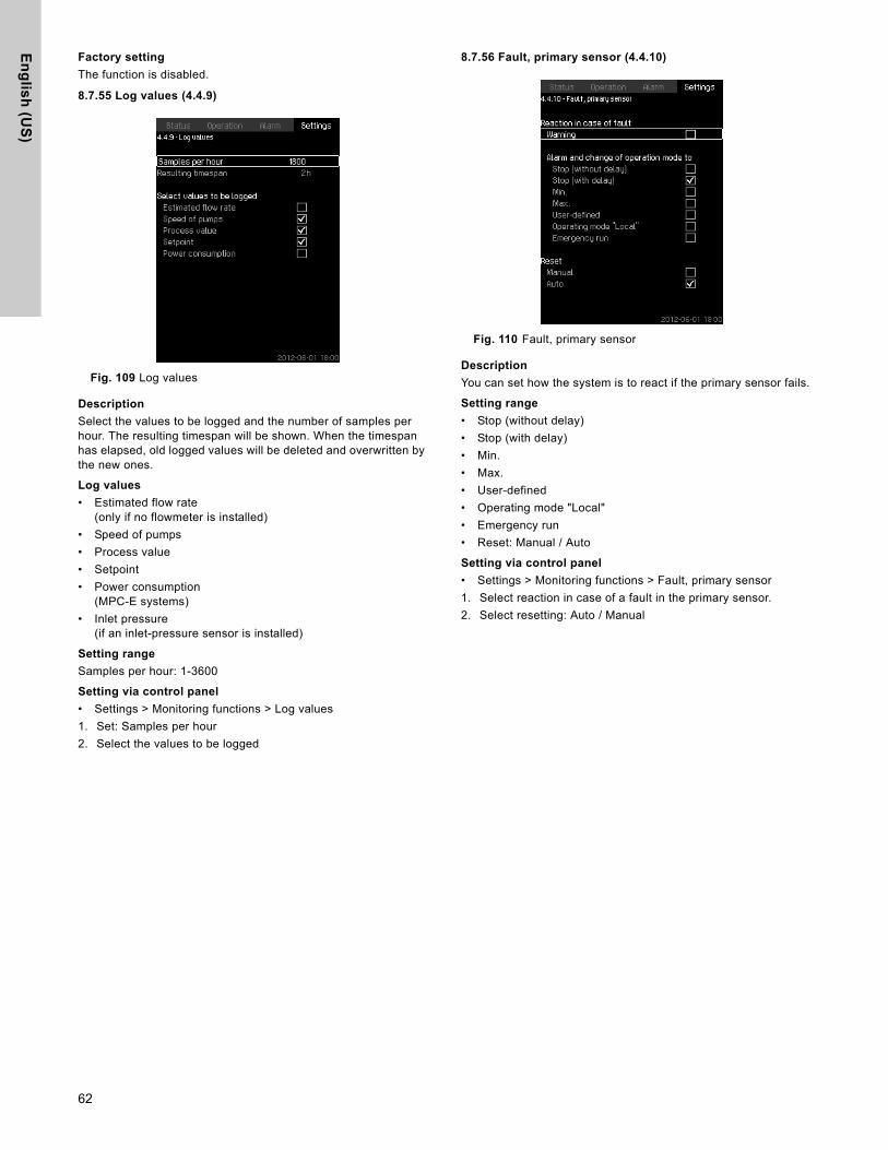
En
glis
h (U
S)
Factory setting
The function is disabled.
8.7.55 Log values (4.4.9)
Fig. 109 Log values
Description
Select the values to be logged and the number of samples per hour. The resulting timespan will be shown. When the timespan has elapsed, old logged values will be deleted and overwritten by the new ones.
Log values
• Estimated flow rate(only if no flowmeter is installed)
• Speed of pumps
• Process value
• Setpoint
• Power consumption(MPC-E systems)
• Inlet pressure(if an inlet-pressure sensor is installed)
Setting range
Samples per hour: 1-3600
Setting via control panel
• Settings > Monitoring functions > Log values
1. Set: Samples per hour
2. Select the values to be logged
8.7.56 Fault, primary sensor (4.4.10)
Fig. 110 Fault, primary sensor
Description
You can set how the system is to react if the primary sensor fails.
Setting range
• Stop (without delay)
• Stop (with delay)
• Min.
• Max.
• User-defined
• Operating mode "Local"
• Emergency run
• Reset: Manual / Auto
Setting via control panel
• Settings > Monitoring functions > Fault, primary sensor
1. Select reaction in case of a fault in the primary sensor.
2. Select resetting: Auto / Manual
62

En
gli
sh
(U
S)
8.7.57 Functions, CU 352 (4.5)Fig. 111 Functions, CU 352
Description
Make the basic settings of the CU 352 in this submenu.
CU 352 comes with most of these settings, or they are made at start-up and normally not to be changed.
The service language, English, can be selected for service purposes. If no buttons are touched for 15 minutes, the display will return to the language selected at start-up or to the language set in Display language (4.5.1).
Setting range
• Activation of service language, English
• Re-activation of start-up wizard.(After start-up, the wizard is inactive.)
• Selection of display language
• Selection of display units
• Setting date and time
• Selection of password for menu "Operation" and "Settings"
• Setting of Ethernet communication.
• Setting of GENIbus number.
• Reading of software status.
8.7.58 Display language (4.5.1)
Fig. 112 Display language
Description
Here you select the language for the CU 352 display.
Setting range
• English
• German
• Danish
• Spanish
• Finnish
• French
• Greek
• Italian
• Dutch
• Polish
• Portuguese
• Russian
• Swedish
• Chinese
• Korean
• Japanese
• Czech
• Turkish
• Hungarian
• Bulgarian
Setting via control panel
• Settings > Functions, CU 352
Factory setting
The display language is English. It can be changed at start-up.
NoteNoteIf the service language is selected, the symbol will be shown to the right of the top line of all displays.
63

En
glis
h (U
S)
8.7.59 Units (4.5.2)
Fig. 113 Units
Description
Here you can select units for the various parameters.
Select between SI and imperial units. You can also select other units for the individual parameters.
Setting range
Setting via control panel
• Settings > Functions > CU 352 > Units
Set unit standard, measuring parameter and specific unit. See the example in fig. 114.
Fig. 114 Example of selection of units
Factory setting
The setting is done in the start-up wizard and depends on the application.
ParameterBasic setting
Possible unitsSI US
Pressure bar psikPa, MPa, mbar, bar, m, psi
Differential pressure m psikPa, MPa, mbar, bar, m, psi
Head m ft m, cm, ft, in
Level m ft m, cm, ft, in
Flow rate m3/h gpmm3/s, m3/h, l/s, gpm, yd3/s, yd3/min, yd3/h
Volume m3 gal l, m3, gal, yd3
Specific energy kWh/m3 Wh/galkWh/m3, Wh/gal, Wh/kgal, BTU/gal, HPh/gal
Temperature °C °F K, °C, °F
Differential temperature K K K
Power kW HP W, kW, MW, HP
Energy kWh kWhkWh, MWh, BTU, HPh
NoteNoteIf units are changed from SI to imperial or vice versa, all individually set parameters will be changed to the basic setting in question.
64

En
gli
sh
(U
S)
8.7.60 Date and time (4.5.3)Fig. 115 Date and time
Description
You can set date and time as well as how they are to be shown in the display.
The clock has a built-in rechargeable voltage supply which can supply the clock for up to 20 days if the voltage supply to the system is interrupted.
If the clock is without voltage for more than 20 days, it must be set again.
Setting range
The date can be set as day, month and year. The time can be set as a 24-hour clock showing hours and minutes.
There are three formats.
It is also possible to select if Sunday or Monday is to be the first day of week.
Setting via control panel
• Settings > Functions, CU 352 > Date and time
1. Select and set:
2. Day, Month, Year, Hours, Minutes
3. Select format
4. Select "Sunday" or "Monday" under "First day of week"
Factory setting
Local time.
8.7.61 Password (4.5.4)
Fig. 116 Password
Description
You can limit the access to menu "Operation" and "Settings" by means of a password. If the access is limited, it is not possible to view or set any parameters in the menus.
The password must consist of four digits and may be used for both menus.
Setting via control panel
• Settings > Functions, CU 352 > Password
1. Select the password to be enabled
2. Select: Enter password The first digit of the password is flashing
3. Select digitThe second digit of the password is flashing
4. Repeat these steps if it is necessary to enable the other password
Factory setting
The "Operation" menu password is deactivated and the "Settings" menu password is activated. The password factory setting is "1234".
Examples of format
2005-09-27 13:49
27-09-2005 13:49
9/27/2005 1:49pm
NoteNote
If the system has been without voltage for more than 20 days since it left the factory, the clock may have returned to the original setting: 01-01-2005 0:00.
Date and time may have been changed during the setting of the system.
There is no automatic changeover to/from daylight-saving time.
NoteNote If you have forgotten the password(s), contact Grundfos.
65

En
glis
h (U
S)
8.7.62 Ethernet (4.5.5)
Fig. 117 Ethernet
Description
The CU 352 is equipped with an Ethernet connection for communication with a computer, either direct or via Internet. See also section 8.8.1 Ethernet.
8.7.63 GENibus number (4.5.6)
Fig. 118 GENibus number
Description
CU 352 can communicate with external units via an RS-485 interface (option). For further information, see fig. 120 and section 8.8.2 GENIbus.
Communication is carried out according to the Grundfos bus protocol, GENIbus, and enables connection to a building management system or another external control system.
Operating parameters, such as setpoint and operating mode, can be set via the bus signal. Furthermore, status about important parameters, such as actual value and input power, and fault indications can be read from the CU 352.
Contact Grundfos for further information.
Setting range
The number can be set between 1 and 64.
Setting via control panel
• Settings > Functions, CU 352 > GENibus number
Factory setting
No number has been set.
8.7.64 Software status (4.5.9)
Fig. 119 Software status
Description
This display shows the status of the software installed in the CU 352. Furthermore, the version code and the product numbers of configuration files (GSC) read into the unit are shown. It is also possible to upgrade the software version. Contact Grundfos for further information.
66

En
gli
sh
(U
S)
8.8 Data communicationCU 352 is equipped with a hardware enabling communication with external units, such as a computer, via an external GENIbus or Ethernet connection.
Fig. 120 Data communication via external GENIbus and Ethernet connection
8.8.1 Ethernet
Ethernet is the most widely used standard for local networks (LAN). The standardization of this technology has created some of the easiest and cheapest ways of creating communication between electric units, for instance between computers or between computers and control units.
The web server of the CU 352 makes it possible to connect a computer to the CU 352 via an Ethernet connection. The user interface can thus be exported from the CU 352 to a computer so that the CU 352 and consequently the system can be monitored and controlled externally.
In order to use the web server, you must know the IP address of the CU 352. All network units must have a unique IP address to communicate with each other. The IP address of the CU 352 from factory is 192.168.0.102.
Alternatively to the factory-set IP address, it is possible to use a dynamic assignment of IP address. This is possible by activating a DHCP (Dynamic Host Configuration Protocol) in the CU 352 or via the web server. See the example in fig. 121.
Fig. 121 Example of setting of Ethernet
Dynamic assignment of an IP address for the CU 352 requires a DHCP server in the network. The DHCP server assigns a number of IP addresses to the electric units and makes sure that two units do not receive the same IP address.
A standard Internet browser is used for connection to the web server of the CU 352.
If you want to use the factory-set IP address, no changes are required in the display. Open the Internet browser and enter the IP address of the CU 352.
If you want to use dynamic assignment, you must enable the function by selecting "Use DHCP" and clicking [ok]. A check mark shows that the function has been enabled.
Open the Internet browser and enter the host name of the CU 352 instead of the IP address. The Internet browser will now try to connect to the CU 352. The host name can be read in the display, but can only be changed by either a GSC file (configuration file) or via a web server. See Change of network setting on page 68.
This is the first display shown when connecting to the CU 352.
Fig. 122 Connection to CU 352
TM
05
32
35
10
12
Intranet
Internet
External GENIbus connection
Ethernet connection
External GENIbus module (option)
Grundfos CIU communication interface
Third-party gateway
NoteNoteGrundfos recommends that you protect the connection to the CU 352 according to your safety requirements in consultation with the system administrator.
NoteNote A host name is required to use DHCP.
TM
03 2
04
8 35
05
67

En
glis
h (U
S)
Factory setting
User name: adminPassword: admin
When you have entererd user name and password, a Java Runtime Environment application starts up in the CU 352, provided that it has been installed on the computer. If this is not the case, but the computer is connected to Internet, then use the link on the screen to download and install the Java Runtime Environment application.
Fig. 123 Display with link to the JavaScript® application
The Java Runtime Environment application will then export the CU 352 user interface (including display and operating panel) to the computer screen. It is now possible to monitor and control the CU 352 from the computer.
Fig. 124 Network setting
Change of network setting
When connection to the web server of the CU 352 has been established, it is possible to change the network setting.
Fig. 125 Change of network setting
1. Click [>Network admin].
2. Enter the changes.
3. Click [Submit] enable the changes.
Change of password
Fig. 126 Change of password
1. Click [Change password].
2. Enter the new password.
3. Click [Submit] save the new password.
8.8.2 GENIbus
By installing a GENIbus module in the CU 352 it is possible to connect the system to an external network. The connection can take place via a GENIbus-based network or a network based on another fieldbus protocol via a gateway. See examples in fig. 120. For further information, contact Grundfos.
The gateway may be a Grundfos CIU communication interface or a third-party gateway. For further information on the CIU, see WebCAPS, or contact Grundfos.
TM
03
204
9 3
505
TM
05
32
36
10
12
TM
03
20
50
35
05
TM
03
20
51
35
05
68

En
gli
sh
(U
S)
9. External variable frequency driveExternal variable frequency drives used in Hydro MPC booster system variants -F, -EF and -EDF come with the manufacturer’s factory settings. See tables below.
At start-up, the factory settings must be changed to the Grundfos settings in the tables below.
In order not to affect the functions of the CU 352 at optimum operation, only the parameters shown should be adjusted. Other parameters should be as set from factory.
9.1 *VLT FC 202
Press [EXTEND MENU] to access all parameters.
Factory setting of VLT FC 200
To recall the factory settings of all parameters, follow one of the procedures below:
1. Select parameter 14-22
2. Press [OK]
3. Select "initialization" (for NLCP select "2")
4. Press [OK]
5. Disconnect the power supply
6. Reconnect the power supply
7. All parameters are now factory-set, except RFI 1, protocol, address, baud rate, minimum response delay, maximum response delay, maximum inter-char delay, operating data, historic log and fault log.
or
1. Disconnect the power supply
2. Press and hold [STATUS] + [MAIN MENU] + [OK] and reconnect the power supply
3. All parameters are now factory-set, except operating hours, the number of power-ups and overtemps and overvolts. Grundfos setting
Parameter Function Value
001 Language English
002 Motor speed unit Hz
003 Regional settings North America
020 Display line 1.1. Power [HP]
021 Display line 1.2 Motor voltage
022 Display line 1.3 Motor current
023 Display line 2 Large Frequency
024 Display line 3 Large Speed [rpm]
100 Configuration mode Open loop
103 Torque characteristics Variable torque
121 Motor power [HP] Nameplate
122 Motor voltage Nameplate
123 Motor frequency Nameplate
124 Motor current Nameplate
125 Motor nominal speed Nameplate
190 Motor thermal protection ETR trip 1
302 Minimum reference 20.000 Hz
303 Maximum reference 60.000 Hz
304 Reference function External preset
310 Preset reference 100.00%
313 Reference site Remote
341 Ramp 1 ramp up time 1.50 s
342 Ramp 1 ramp down time 3.00 s
412 Motor speed low limit [HZ] 0.0 Hz
414 Motor speed high limit [HZ] 62.0 Hz
419 Max. Output frequence 65.0 Hz
510 Terminal 18 digital input Star
513 Terminal 29 digital input Preset reference on
540.0 Function relay Drive ready
542.0 Off delay, relay 2.00 s
610 Terminal 53 low voltage 0.00 V
611 Terminal 53 high voltage 10.00 V
614Terminal 53 low ref. / feedb.
20.000 Hz
615Terminal 53 high ref. / feedb.
60.000 Hz
1400 Switching pattern 60 AVM
1401 Switching frequency 5.0 kHz
69

En
glis
h (U
S)
9.2 Configuration of E-pump(s), if any
Before the Hydro MPC system is ready for test, the E-pumps have to be set.
• Turn on the power supply to the E-pumps by means of the automatic circuit breaker.
• Set with R100 the GENibus number to the same number as that of the pump.
• (Number = 1 for pump No 1, etc.)
Fig. 127 Pumps numbered from left to right.
Configuration of the CUE(s), if any
The manufacturer’s factory settings of the CUE used in Control MPC must be changed to the Control MPC settings before it is ready to test.
To configure the CUE:
1. Switch off the power supply to the CUE(s) by means of the automatic circuit breaker.
2. Connect the PC Tool to the GENibus terminals of the CUE which you want to configure.
3. Turn on the power supply to the CUE.
4. Start the PC Tool E-products.
5. When communication has been established, the PC Tool "Network list" will display the icon for the CUE.
6. Select the CUE in "Network list."
7. Select the PC Tool function "Custom configuration."
8. Go to section "GENibus," and set the "unit number" to the same number as that of the CUE. (Number = 1 for CUE No. 1, etc.)
Note: Steps 7 and 8 are not necessary for the CUE in Hydro MPC-F.
9. Go to section "General," select the "Pump Family" and enter motor data. See fig. 117.
Fig. 128 "Custom configuration" (General)
10. Select the PC Tool function "Standard configuration."
11. Go to section "Searcy by" and select "Number."
12. Type the GCS file number "97685157" in the "Configuration No." field and click "Search Now."
13. Select the file from the "Configuration files" field and click "Send."
14. Switch on the power supply to the next CUE with the main switch, and repeat steps 6 to 13 for each CUE.
NoteNote The pumps are numbered from left to right, while facing the suction.
GrA
0533
_US
081
2
NoteNote Collect the motor data from the motor nameplate.
TM
04
462
8_U
S 0
812
NoteNote The bus termination dip switch on the last CUE drive should be switched to the "ON" position.
70

En
gli
sh
(U
S)
10. Fault findingWarning
Before starting fault finding, switch off the power supply for at least five minutes. Make sure that the power supply cannot be accidentally switched on.
Fault Possible cause Remedy
Pumps do not run when started.
The actual pressure is higher than or equal to the setpoint.
Wait until the pressure has dropped, or lower the pressure on the discharge side of the Hydro MPC and check that the pumps start.
Power supply disconnected. Connect the power supply.
Main switch cut out. Cut in the main switch.
Main switch is defective. Replace the main switch.
Motor protection is activated. Contact Grundfos.
Motor is defective. Repair or replace the motor.
Pressure transmitter fault- Pressure transmitter is defective.
Replace the pressure transmitter. Transmitters with 0-20 mA or 4-20 mA output signals are monitored by the Hydro MPC.
- Cable is broken or short-circuited. Repair or replace the cable.
The pumps start, but stop immediately.The operating pressure is not reached.
Dry running or no inlet pressure.
Reestablish the supply of water to the Hydro MPC. When the inlet pressure has been reestablished, the pumps will restart after 15 seconds.
The Hydro MPC is stopped and cannot restart.
Pressure transmitter fault- Pressure transmitter is defective.
Replace the pressure transmitter. Transmitters with 0-20 mA or 4-20 mA output signals are monitored by the Hydro MPC.
- Cable is broken or short-circuited. Repair or replace the cable.
CU 352 fault- Power supply disconnected.
Connect the power supply.
- The CU 352 is defective. Contact Grundfos.
Unstable water delivery from Hydro MPC (applies to unstable water supply).
Inlet pressure is too low.Check the suction pipe and possible suction strainer.
Suction pipe or pumps partly blocked by impurities.
Clean the suction pipe, strainer or pumps.
Pumps suck air. Check the suction pipe for leakages.
Pressure transmitter is defective. Replace the pressure transmitter.
Pumps are running, but deliver no water.
The valves are closed. Open the valves.
Suction pipe or pumps blocked by impurities.
Clean the suction pipe or pumps.
Non-return valve blocked in closed position.Clean the non-return valve. The non-return valve must move freely.
Suction pipe leaky. Check the suction pipe for leakages.
Air in suction pipe or pumps.Vent and prime the pumps. Check the suction pipe for leakages.
The Hydro MPC is unable to reach the setpoint.
Too high consumption.Reduce consumption (if possible).Install a bigger Hydro MPC booster system.
Too many standby pumps selected. Reduce the number of standby pumps.
Pipe fracture or leakage in the system.Check the system, and repair damages, if necessary.
Leakage from the shaft seal.Shaft seal is defective. Replace the shaft seal.
Height adjustment of pump shaft inaccurate.
Readjust the shaft height.
Noise.
The pumps are cavitating.Clean the suction pipe/pumps and possibly the suction strainer.
The pumps do not rotate freely (friction resistance) due to inaccurate height adjustment of the pump shaft.
Readjust the shaft height.
Very frequent starts and stops. Wrong diaphragm tank precharge pressure. Set correct precharge pressure.
71

En
glis
h (U
S)
11. Maintenance
11.1 CU 352
The CU 352 is maintenance-free. Keep the unit clean and dry, and protect it against direct sunlight. Ambient temperature, see section 14. Technical data.
11.2 Pumps
Pump bearings and shaft seal are maintenance-free.
11.3 Motor bearings
Motors without lubricating nipples are maintenance-free.
Motors with lubricating nipples should be lubricated with a high-temperature lithium-based grease. See the instructions on the fan cover of Grundfos motors.
In the case of seasonal operation (motor is idle for more thansix months of the year), we recommend to grease the motor when the pump is taken out of operation.
12. Frost protectionPumps which are not being used during periods of frost should be drained to avoid damage.
Drain the pump by loosening the air vent screw in the pump head and by removing the drain plug from the base.
Do not tighten the air vent screw and fit the drain plug until the pump is to be used again.
13. ShutdownSwitch off the main switch to take the system out of operation.
Take individual pumps out of operation by switching off the corresponding motor-protective circuit breaker, automatic circuit breaker or fuse.
14. Technical data
14.1 Pressure
Inlet pressure
Hydro MPC booster systems can operate with a positive inlet pressure (precharged pressure system) or with a negative inlet pressure (i.e vacuum at the inlet manifold).
We recommend to calculate the inlet pressure in these cases:
• Water is drawn through long pipes
• Water is drawn from depths
• Inlet conditions are poor
To avoid cavitation, make sure that there is a minimum inlet pressure on the suction side of the booster system. The minimum inlet pressure in bar can be calculated as follows:
H = Pb - NPSH - Hf - Hv - Hs
Pb = Barometric pressure in feet (33.9 feet at sea level). In closed systems, pb indicates system pressure in feet.
Hf = Friction loss in suction piping in feet. (At the highest flow the pump will be delivering.)
Hv = Vapor pressure in feet.
NPSH = Net Positive Suction Head in feet.NPSH can be read from the NPSH curve at the maximum capacity at which the pump will run.(See installation and operating instructions forCR, CRI, CRN.)
Hs = Safety margin = minimum 2 feet.
If "H" is calculated as positive, the pump can operate at a suction of maximum "H" feet. If "H" is calculated as negative, an inlet pressure (psia) of minimum "H" feet is required.
Maximum inlet pressure
See the CR, CRI, CRN installation and operating instructions.
Operating pressure
As standard, the maximum operating pressure is 230 psi [16 bar].
On request, Grundfos offers Hydro MPC booster systems with a maximum operating pressure higher than 230 psi [16 bar].
14.2 Temperature
Liquid temperature: 32 °F to +158 °F
Ambient temperature: 32 °F to +104 °F
14.3 Relative humidity
Max. relative humidity: 95%
14.4 Sound pressure
For sound pressure level, see the installation and operating instructions for the CR pumps.
The sound pressure level for a number of pumps can be calculated as follows:
Lmax. = Lpump + (n – 1) x 3
Lmax. = Maximum sound pressure level
Lpump = Sound pressure level of one pump
n = Number of pumps
Warning
Before starting work on the product, switch off the power supply.
Lock the main switch with a padlock to ensure that the power supply cannot be accidentally switched on.
Warning
Make sure that the escaping hot or cold liquid does not cause injury to persons or damage to the equipment.
Warning
The conductors in front of the main disconnect switch are still energized.
Lock the main disconnect switch with a padlock to ensure that the power supply cannot be accidentally switched on.
NoteNote
In this manual, the term "inlet pressure" is defined as the pressure/vacuum which can be measured immediately before the booster system.
72

En
gli
sh
(U
S)
15. Electrical dataSupply voltage
See nameplate of the system.
Backup fuse
See the wiring diagram supplied with the system.
Digital inputs
Analog inputs
Digital outputs (relay outputs)
All digital outputs are potential-free relay contacts.
Inputs for PTC sensor/thermal switch
For PTC sensors to DIN 44082. Thermal switches can also be connected.
16. Further product documentationFurther information about the system can be found in the following documents.
All documents are available in WebCAPS on Grundfos’ homepage, www.grundfos.com.
* Only relevant for Hydro MPC booster systems with external frequency drive, -E (CUE), -F.
** Only relevant for Hydro MPC-E with CRE booster systems.
*** A wiring diagram is supplied with the booster system.
17. DisposalThis product or parts of it must be disposed of in an environmentally sound way:
1. Use the public or private waste collection service.
2. If this is not possible, contact the nearest Grundfos company or service workshop.
Subject to alterations.
Open-circuit voltage: 24 VDC
Closed-circuit current: 5 mA, DC
Frequency range: 0-4 Hz
NoteNote All digital inputs are supplied with PELV voltage (Protective Extra-Low Voltage).
Input current and voltage:0-20 mA4-20 mA0-10 V
Tolerance: ± 3.3 % of full scale
Repetitive accuracy: ± 1 % of full scale
Input resistance, current: < 250 ΩInput resistance, voltage, CU 352: 50 kΩ ± 10 %
Input resistance, voltage, IO 351: > 50 kΩ ± 10 %
Supply to sensor:24 V, maximum 50 mA, short-circuit protected
NoteNote All analog inputs are supplied with PELV voltage (Protective Extra-Low Voltage).
Maximum contact load: 240 VAC, 2 A
Minimum contact load: 5 VDC, 10 mA
NoteNoteSome outputs have a common C terminal. For further information, see the wiring diagram supplied with the system.
Open-circuit voltage: 12 VDC ± 15 %
Closed-circuit current: 2.6 mA, DC
NoteNote Inputs for PTC sensors are electrically separated from the other inputs and outputs of the system.
Title FrequencyPublication
number
Product Guide
Grundfos Hydro MPC 60 Hz L-BPQ-PG-01
Grundfos Hydro MPC 60 Hz L-CR-PG-001
Grundfos CUE Frequency drive *
60 Hz L-CUE-PG-01
Installation and operating instructions
CR, CRI, CRN 60 Hz L-CP-TL-003
Grundfos E-pumps ** 60 Hz L-ML-PG-001
Service documentation
Service instructions 50/60 Hz 96646712
Service kit catalogue 50/60 Hz 96488862
Other documentation
*** - -
73

Gru
nd
fos
co
mp
an
iesUSA
GRUNDFOS Pumps Corporation 17100 West 118th TerraceOlathe, Kansas 66061Phone: +1-913-227-3400 Telefax: +1-913-227-3500
CanadaGRUNDFOS Canada Inc. 2941 Brighton Road Oakville, Ontario L6H 6C9 Phone: +1-905 829 9533 Telefax: +1-905 829 9512
MéxicoBombas GRUNDFOS de México S.A. de C.V. Boulevard TLC No. 15Parque Industrial Stiva AeropuertoApodaca, N.L.C.P. 66600Phone: +52-81-8144 4000 Telefax: +52-81-8144 4010
www.grundfos.us
Being responsible is our foundationThinking ahead makes it possible
Innovation is the essence
The name Grundfos, the Grundfos logo, and the payoff Be–Think–Innovate are registrated trademarks owned by Grundfos Management A/S or Grundfos A/S, Denmark. All rights reserved worldwide.
L-BPQ-TL-01 1012
ECM: —


