METALLURGY TRAINING MODULE 7 REV. A01 BY JDD DATE 03/05/13 HISC & DNV-RP- F112 Page 1 of 25 APPROVED DATE Introduction Hydrogen induced stress cracking, or HISC, has gained a lot of attention in the subsea oil industry over the past 10 years or so because of several very costly failures of duplex stainless steel (DSS) parts. It is a form of environmentally assisted cracking in which hydrogen ions from cathodic protection (C/P) are electrostatically charged into a susceptible metal and embrittle it. Failure may occur at stresses well below the metal’s yield strength. Susceptible metals include high strength carbon and low alloy steels, high strength martensitic stainless steels, and duplex stainless steels. All three of these alloy families are used extensively subsea under cathodic protection. It is thus very important that design engineers become familiar with the susceptibility of these materials to HISC, what their design limitations are, and how the risk of HISC can be eliminated. Duplex stainless steels are particularly at risk. DNV RP F1122, Design of Duplex Stainless Steel Subsea Equipment Exposed to Cathodic Protection, was written to provide guidelines for the safe usage of duplex stainless steels under C/P shortly after several of the high profile failures had occurred. We will examine this standard in some detail. HISC is a form of hydrogen embrittlement (HE) that occurs on subsea parts under cathodic protection. The exact mechanism of embrittlement has not been clearly defined yet. It is thought that atomic hydrogen collects at the tip of a microscopic crack in the metal. Here they can interact with dislocations causing a reduction of bond strength between the metal atoms. It is also believed that the hydrogen ions from the electrolysis of seawater are electrostatically charged directly into the cathode without first forming an adsorbed hydrogen atom. HISC in a susceptible metal depends on the amount of hydrogen charged into the metal, the mobility of the hydrogen within the metal, and the location of the hydrogen buildup within the metal. The amount of hydrogen that is charged into the metal is governed by the cathodic protection system parameters and the use of protective coatings. The ability of the hydrogen to move around in the metal is primarily dependent on the microstructure of the metal. The diffusivity of hydrogen in BCC (ferritic) materials is high, but the total amount that can be absorbed into a BCC lattice is limited – the center of the cubic lattice already has an atom in it. In contrast the diffusivity of hydrogen in FCC (austenitic) materials is low, but the total amount that can absorbed into an FCC lattice is much greater than for BCC (the center of the FCC cube is empty). This makes ferritic steels much more susceptible to HISC than austenitic steels. Coatings act as barriers to hydrogen diffusion. If seawater can’t come into contact with the metal surface being cathodically protected, electrolysis cannot occur and no hydrogen ions are formed. Coatings may mitigate the risk of HISC, but they can never be used as the sole means for preventing HISC in a susceptible metal.
Transcript
METALLURGY TRAINING MODULE 7 REV. A01
BY
JDD
DATE
03/05/13 HISC & DNV-RP- F112
Page 1 of 25 APPROVED
DATE
Introduction
Hydrogen induced stress cracking, or HISC, has gained a lot of attention in the subsea oil industry over the past 10 years or so because of several very costly failures of duplex stainless steel (DSS) parts. It is a form of environmentally assisted cracking in which hydrogen ions from cathodic protection (C/P) are electrostatically charged into a susceptible metal and embrittle it. Failure may occur at stresses well below the metal’s yield strength. Susceptible metals include high strength carbon and low alloy steels, high strength martensitic stainless steels, and duplex stainless steels. All three of these alloy families are used extensively subsea under cathodic protection. It is thus very important that design engineers become familiar with the susceptibility of these materials to HISC, what their design limitations are, and how the risk of HISC can be eliminated. Duplex stainless steels are particularly at risk. DNV RP F1122, Design of Duplex Stainless Steel Subsea Equipment Exposed to Cathodic Protection, was written to provide guidelines for the safe usage of duplex stainless steels under C/P shortly after several of the high profile failures had occurred. We will examine this standard in some detail. HISC is a form of hydrogen embrittlement (HE) that occurs on subsea parts under cathodic protection. The exact mechanism of embrittlement has not been clearly defined yet. It is thought that atomic hydrogen collects at the tip of a microscopic crack in the metal. Here they can interact with dislocations causing a reduction of bond strength between the metal atoms. It is also believed that the hydrogen ions from the electrolysis of seawater are electrostatically charged directly into the cathode without first forming an adsorbed hydrogen atom. HISC in a susceptible metal depends on the amount of hydrogen charged into the metal, the mobility of the hydrogen within the metal, and the location of the hydrogen buildup within the metal. The amount of hydrogen that is charged into the metal is governed by the cathodic protection system parameters and the use of protective coatings. The ability of the hydrogen to move around in the metal is primarily dependent on the microstructure of the metal. The diffusivity of hydrogen in BCC (ferritic) materials is high, but the total amount that can be absorbed into a BCC lattice is limited – the center of the cubic lattice already has an atom in it. In contrast the diffusivity of hydrogen in FCC (austenitic) materials is low, but the total amount that can absorbed into an FCC lattice is much greater than for BCC (the center of the FCC cube is empty). This makes ferritic steels much more susceptible to HISC than austenitic steels. Coatings act as barriers to hydrogen diffusion. If seawater can’t come into contact with the metal surface being cathodically protected, electrolysis cannot occur and no hydrogen ions are formed. Coatings may mitigate the risk of HISC, but they can never be used as the sole means for preventing HISC in a susceptible metal.
METALLURGY TRAINING MODULE 7 REV. A01
BY
JDD
DATE
03/05/13 HISC & DNV-RP- F112
Page 2 of 25 APPROVED
DATE
The risk of HISC occurring in a given metal increases with increasing strength, inclusion content, stress (applied or residual), and cold work. These provide defects in the microstructure where hydrogen can accumulate. They also make it easier for the hydrogen to diffuse into the metal. The entry of hydrogen into a metal part is greatly enhanced if the part is being strained while under C/P. This is particularly true for DSS. Strain that occurs under a constant load at ambient temperature and at stresses below the metal’s yield strength is called cold creep. Engineers must be careful to limit the likelihood and extent of cold creep in their designs.
CARBON & LOW ALLOY STEELS
The HISC susceptibility of carbon and low alloy steels is primarily a function of their strength. This is the reason why DNV RP B401, Cathodic Protection Design, limits the maximum allowed hardness for carbon and low alloy steels used for subsea equipment under CP to 35HRC (350HV) maximum. API 17D limits bolting to 35 HRC maximum for the same reason. Untempered martensite in these steels is particularly susceptible to HISC. Untempered martensite may form in the heat affected zone (HAZ) of welds. Welds must be post weld stress relieved which will temper back the fresh martensite to 35 HRC (350 HV) maximum. Carbon steels can be used in the as-welded condition provided the carbon equivalency is controlled and that the weld procedure qualification limits hardness to 35 HRC (350 HV) maximum. . A maximum hardness of 35 HRC equates to a yield strength of about 135 ksi in common bolting materials (4140, 4340, etc.) up to roughly 2” in diameter. Of course the specified yield strength must be kept well below this number. As a general rule of thumb, carbon and low alloy steels with specified minimum yield strengths not exceeding 105ksi and with a maximum hardness of 35 HRC have excellent HISC resistance. Higher specified minimum yield strengths used in conjunction with 35HRC maximum should only be used after consulting a metallurgist. Many customers impose a more restrictive hardness than 35 HRC on carbon and low alloy steel fasteners. To be conservative, a maximum hardness of 32 HRC or 33 HRC is often specified. This takes into account the 1-2 HRC point scatter inherent in Rockwell testing. B7 properties (105 ksi SMYS) can still be met in bolting up to 2” at 32 HRC. Bolting is critical. Unlike many other pressure containing components, bolts are typically highly loaded across their entire cross section. The failure of one bolt in a bolt circle by HISC can increase the load on all the remaining bolts making them more susceptible to HISC failure. API has issued a new specification API Spec 20E, Alloy and Carbon Steel Bolting for Use in the Petroleum and Natural Gas Industries, partly as a result of some high profile HISC failures of B7 fasteners. These failures occurred in fasteners that had been
METALLURGY TRAINING MODULE 7 REV. A01
BY
JDD
DATE
03/05/13 HISC & DNV-RP- F112
Page 3 of 25 APPROVED
DATE
individually hardness tested and met the 35 HRC maximum. The problem was that the bolting material was heavily banded. Banding describes the appearance of the microstructure of a rolled product where chemical segregation has occurred (see Figure 1). The chemical compositions of the light and dark colored bands in Figure 1 vary and consequently their response to heat treatment varies. Properties including hardness will be different. The spacing between the bands is very small so a Rockwell indentation spans across many bands and gives an average, bulk hardness value. If we were to microhardness each band, the results could be very different! .
Figure 1: Banding
There are various causes of banding, but all stem from chemical segregation that occurs during solidification. The elongated bands of course form during the rolling (hot working) of the bar stock used to make the fastener. Carbon often segregates out particularly if boron is present. Boron is sometimes added to steels to increase hardenability. A band with a high carbon content and boron present may have a hardness equivalent to 45-55 HRC or higher while an adjacent low carbon band may be 20-30 HRC. Rockwell testing a finished fastener such as a stud will not detect this condition, but will produce an average hardness that may very well meet 35 HRC maximum. The high hardness bands are very susceptible to HISC where cracks can initiate under C/P. API Spec 20E addresses banding and requires that fastener microstructures be checked for excessive banding.
METALLURGY TRAINING MODULE 7 REV. A01
BY
JDD
DATE
03/05/13 HISC & DNV-RP- F112
Page 4 of 25 APPROVED
DATE
MARTENSITIC STAINLESS STEELS
Martensitic stainless steels like 410 and F6NM are susceptible to HISC at high strength levels. Like carbon and low alloy steels, the martensitic stainless steels should be limited to 35 HRC (350 HV) maximum when used under cathodic protection. There are many new, low carbon martensitic grades now available that were developed for OCTG (Oil Country Tubular Goods) that require welding. They have a chemistry similar to F6NM, but with a maximum carbon content of 0.02%. They are easily welded because of their low carbon content. Collectively these alloys are known as the super martensitic stainless steels. The mechanical properties in the as-welded condition show acceptable ductility and toughness. As-welded hardness is below 350 HV. All of this led producers of the super martensitic grades to claim they could be safely used in the as-welded condition. Unfortunately fresh martensite can form from retained austenite in the heat affected zone of the weld making the weldment susceptible to HISC. Bottom line is that these materials must always be stress relieved after welding if used subsea under C/P.
DUPLEX STAINLESS STEELS
Duplex stainless steels (DSS) have found wide spread use in subsea equipment because of their unique combination of strength, weldability, corrosion resistance, and relatively low cost. The 22 Cr DSS have a corrosion resistance on par with 316, but has almost twice 316’s yield strength. The 25 Cr DSS has even better corrosion resistance and higher strength. Both can be welded without stress relieving because of their low carbon content. This is an enormous advantage when fabricating a subsea manifold or pipeline. DSS is often specified when sweet (CO2) corrosion is an issue. There is really no inexpensive alternative. Martensitic stainless steels all require stress relieving after welding and clad carbon/low alloy steels or nickel base alloys are hugely expensive. Austenitic stainless steels are not strong enough. Unfortunately DSS can become very susceptible to HISC under some circumstances that relate both to the material properties and to the design of the DSS part. It is absolutely essential that an engineer wanting to use DSS for a subsea part under C/P understand the design limitations of this material. Duplex stainless steels are a different type of animal from our other steels. The key to the successful use of DSS under C/P is a thorough understanding of its metallurgy.
DSS are carefully alloyed so that a microstructure consisting of approximately equal amounts of ferrite and austenite is attained. The ferrite phase forms a continuous matrix
METALLURGY TRAINING MODULE 7 REV. A01
BY
JDD
DATE
03/05/13 HISC & DNV-RP- F112
Page 5 of 25 APPROVED
DATE
with “islands” (isolated grains) of austenite (see Figure 2). As might be expected, there is some alloy partitioning between the ferrite and austenite phases so their compositions are not the same. Nickel and nitrogen, both strong austenite formers, will tend to concentrate in the austenite. Strong ferrite formers such as chromium and molybdenum will tend to concentrate in the ferrite. Both phases will have approximately the same pitting resistance equivalency number (PREN = Cr% = 3.3Mo% + 16N%). Ferrite will be the first solid phase to form as a molten DSS alloy begins to solidify.. Austenite will begin to nucleate and grow from the ferrite as the temperature decreases.
Figure 2: Duplex Stainless Steel Microstructure Ideally the microstructure of DSS at room temperature will contain only austenite and ferrite, but unfortunately there are a number of undesirable secondary phases that may be present. DSS are used in the solution annealed and quenched condition. Undesirable secondary phases such as chi, rho, sigma, carbides, nitrides, or other intermetallics may precipitate out within certain temperature ranges during cooling after solution annealing if held for a sufficient length of time within these ranges. The presence of these miscreants can totally screw up the corrosion resistance and toughness of our DSS. If we cool the material as rapidly as possible from the solution annealing temperature, there won’t be enough time in the offending temperature bands for these troublesome secondary phases to precipitate out. We can get too much of a good thing, however, because too fast a cooling rate may result in less than the desired amount of austenite in the final microstructure. Cooling from the annealing temperature must be rapid enough to prevent the precipitation of undesirable secondary phases, but slow enough to allow sufficient austenite to form. Duplex stainless steels cannot be hardened or strengthened through heat treatment.
Ferrite (Dark)
Austenite (Light)
METALLURGY TRAINING MODULE 7 REV. A01
BY
JDD
DATE
03/05/13 HISC & DNV-RP- F112
Page 6 of 25 APPROVED
DATE
As you would expect, the ferrite and austenite phases have different properties. The ferrite phase has superior chloride stress corrosion cracking resistance compared to the austenitic grades hence the ferrite matrix. This permits DSS to be used at higher temperatures than the austenitic stainless steels in chloride environments. The ferrite is also stronger than the austenite phase. The austenite phase imparts good general corrosion resistance and toughness to the alloy. Together they form a natural composite material. The permeability of hydrogen in ferrite with its BCC structure is high, but the solubility is low. In austenite with its FCC structure the permeability is low, but the solubility is high. Hydrogen that is charged into the microstructure from C/P will tend to accumulate around defects in the ferrite because of the low solubility in the BCC lattice. Stresses will accumulate along the ferrite-austenite grain boundaries as a DSS part is loaded. The ferrite matrix will initially carry the load. The low strength, ductile austenite will plastically deform first. The austenite will strain harden as it deforms and produce a complex stress state along the grain boundaries. The susceptibility of ferrite to HISC is much greater than the susceptibility of the austenite. The ductile austenite will act as an obstacle to crack propagation. In most HISC failures, brittle crack propagation will be in the ferrite phase with the austenite phase failing by ductile overload. Understanding this failure mechanism is the key to the successful use of DSS under C/P. We can reduce the risk of our DSS part failing by HISC if we minimize the distance between the austenite grains (called the austenite spacing). This minimizes the distance that a HISC crack can propagate through the ferrite phase before it is blocked by a tough, crack resistant austenite grain. Austenite spacing is primarily a function of composition, hot work, and heat treatment. The greater the hot work, the finer the austenitic spacing and the greater the HISC resistance. Wrought tubing for instance has significantly more hot work than a large DSS forging and consequently will be more HISC resistant. The HISC resistance of a DSS part is dependent on the orientation of the grain flow in relation to the tensile stresses it sees in service. We can minimize the risk of HISC by properly orientating the grain flow within the part. The greatest driving force for crack growth is transverse to the tensile load direction. By having the grain flow of the part orientated parallel to the direction of greatest tensile stress, crack growth will occur perpendicular to the grain flow. This orientation presents the greatest number of austenite grains (consequently the smallest austenite spacing) in the path of a propagating crack (see Figure 3). Note in Figure 3A that the grain flow is parallel to the longitudinal axis of the flange. A crack growing in the radial direction in the highly stressed weld neck will have to cross the maximum number of austenite grains (the light colored phases). Figure 3B, on the other hand, has the grain flow perpendicular to
METALLURGY TRAINING MODULE 7 REV. A01
BY
JDD
DATE
03/05/13 HISC & DNV-RP- F112
Page 7 of 25 APPROVED
DATE
the axis of the flange. A radial crack can grow through the wall entirely within the ferrite matrix (the dark color phase)!
A - Optimum Grain Flow B – Recipe for Disaster!
Figure 3: Importance of Grain Flow Orientation
Maintaining the proper ferrite/austenite balance is important in preventing HISC in DSS. As we have already learned, the risk of HISC is greater for ferrite than austenite. If there is excess ferrite in the microstructure, then the austenite spacing must be larger and the risk of HISC increases. Avoiding the precipitation of undesirable phases in the microstructure is important for minimizing the risk of HISC. They can act as traps in the ferrite where hydrogen can accumulate. Unlike other steels, the risk of HISC in DSS is fairly independent of the strength level: a 22Cr DSS is just as susceptible to HISC as
METALLURGY TRAINING MODULE 7 REV. A01
BY
JDD
DATE
03/05/13 HISC & DNV-RP- F112
Page 8 of 25 APPROVED
DATE
the stronger 25CR DSS grades. Cold working a DSS, however, will increase its HISC susceptibility. Maintaining the proper ferrite/austenite mix in weldments can be challenging! DSS are easily welded and do not require a stress relief. The problem is to insure a HISC resistant microstructure in the weldment. Heat input is of paramount importance. If the heat input is too low, the weld metal may cool too quickly for the desired amount of austenite to precipitate out resulting in excessive ferrite and poor HISC resistance. Too much heat input may retard the cooling rate and result in unwanted, secondary phases. The filler metal for DSS generally has a higher nickel content than the DSS parts being welded. Nitrogen, a very strong austenite former, is not transferred across the weld arc with the molten filler metal. The increased nickel in the filler metal, also a strong austenite former, will help restore the proper ferrite/austenite balance. Don’t specify fillet welds on DSS parts! They tend to cool very rapidly resulting in excess ferrite in the microstructure that is susceptible to HISC. Great care should be taken to insure that no fillet welds are made on a DSS part or assembly later on in the form of attachment welds or seal welds for fittings, sensors, anodes, etc. Always follow the design guidelines in DNV-RP-F112 for weldment design. Some of the earliest DSS failures by HISC were the result of fillet welds that had cooled too rapidly and ended up having 80- 90% ferrite. The risk of HISC is greatest when a DSS part is under CP and is being strained at the same time. A crack will often initiate at a ferrite/austenite grain boundary and then propagate transgranularly through the ferrite. The austenite, although less susceptible to HISC than the ferrite, may undergo HISC given the high plastic strains (with the resulting cold working) and the high hydrogen charging. A DSS part may undergo dynamic strain at stresses below its yield strength. This is known as cold creep. Cold creep is plastic deformation at ambient temperatures that occurs under a constant load at stresses below the yield strength of the material. HISC susceptibility increase as the total stresses approach the yield strength of the material. Preventing or minimizing cold creep in is one of the engineer’s chief responsibilities when designing DSS parts to avoid failure by HISC. The engineer must take into account strains resulting from applied stresses, residual stresses (resulting from welding, fabrication, etc.), and stress concentration factors. DNV-RP-F112, Design of Duplex Stainless Steel Subsea Equipment Exposed to Cathodic Protection, was written to assist designers on how to perform the appropriate cold creep analysis and minimize the risk of HISC. Most customers invoke this spec for any subsea equipment with DSS components. . Cold work will increase the HISC susceptibility of DSS. Cold working generates numerous defects in the microstructure of the material that acts as traps where hydrogen can accumulate. DSS should always be used in the solution annealed and
METALLURGY TRAINING MODULE 7 REV. A01
BY
JDD
DATE
03/05/13 HISC & DNV-RP- F112
Page 9 of 25 APPROVED
DATE
quenched condition whenever possible. Heavy cold work should be followed by re-solution annealing and water quenching. DSS tubing that is cold bent should have a bend radius as large as possible, but not less than 3.3D where D is the diameter of the tubing. DSS parts should always be coated whenever possible. This is true even for super duplexes that are seawater corrosion resistant. The coating acts as a protective barrier that prevents the seawater from contacting the part surface. This prevents hydrolysis from occurring so hydrogen will not be generated. Coatings cannot be used as the only means for preventing HISC because any holiday in the coating will permit hydrogen to form. In general sacrificial anodes should not be directly mounted on DSS. This avoids having to make attachment welds and avoids damaging the protective coating. It is not practical to coat small diameter DSS tubing (control lines, injection lines, etc.), but fortunately it’s not necessary. Small diameter tubing is very resistant to HISC because it has a very fine grain size due to the high amount hot working it undergoes.
HISC IN OTHER ALLOYS
All of the steels that we have looked at so far either have a predominately ferritic microstructure (carbon and low alloy steels, martensitic stainless steels) or a microstructure that is approximately half ferritic (duplex stainless steel). What about alloys that have an austenitic structure? These include the austenitic stainless steels and nickel base alloys. In the solution annealed and water quenched condition these alloys have excellent HISC resistance. Age hardenable nickel alloys such as 718, 725, 625 Plus™, 925, etc. also have good resistance to HISC with a couple of notable exceptions. Monel K-500™ and X-750 are two nickel base alloys that should never be used for subsea equipment that is cathodically protected because they are prone to HISC failures. Some austenitic alloys may be made susceptible to HISC if heavily cold worked or if highly dynamically strained while under C/P. The HISC resistance of precipitation hardening stainless steels is highly dependent on
their matrix microstructure and their strength level. Grade 660 (A286™) has an
austenitic matrix and has excellent HISC resistance. 17-4 has a martensitic matrix and
can be highly susceptible to HISC depending on heat treatment and strength level. It
can be safely used under C/P as long as it has been solution annealed and then aged
at a minimum of 1150F to a maximum hardness of 33 HRC. There have been a number
of 17-4 failures that have been attributed to various forms of hydrogen embrittlement
including HISC under C/P. The root cause of the failure is almost always improper heat
treatment.
In general it is safe to specify any corrosion resistant alloy for a subsea part that will be
cathodically protected provided the CRA is preapproved by NACE MR0175/ISO 15156
METALLURGY TRAINING MODULE 7 REV. A01
BY
JDD
DATE
03/05/13 HISC & DNV-RP- F112
Page 10 of 25 APPROVED
DATE
for sour service. Sulfide stress cracking (SSC) is an accelerated form of hydrogen
embrittlement and alloys with good SSC resistance will have generally have good HISC
resistance. When in doubt about an alloy, laboratory testing should be performed to
verify its compatibility with cathodic protection.
NICKEL ALLOY BUTTER WELDS
There have been several recent, high profile HISC failures in equipment with 625 butter
welds in the North Sea and the Gulf of Mexico. A “butter weld” is a transition weld
between two different alloys that cannot be welded directly together for various reasons.
The most common reason is that one of the metals being joined requires a post weld
stress relief while the other metal cannot be given the same stress relief without a
degradation of properties. For example, suppose we want to weld a duplex stainless
steel pipe to a 4130 block valve that has been cladded with 625. The weld end
connection of the 4130 block valve is easily welded, but requires a post weld stress
relief of 1150F minimum (assuming sour service). If we weld the DSS pipe directly to
the 4130 and then stress relieve the weldment we will cause sigma phase to precipitate
out in the DSS destroying both its corrosion resistance and its toughness.
We can get around this problem by “buttering” the weld end of the block valve with 625:
that is, we will build up an extension of the weld end connection with 625 weld metal.
Why 625? Because although it does not require a post weld stress relief itself, it can
withstand a stress relief typical of low alloy steel without suffering a major degradation
in properties. Once we’ve added a long enough extension, we’ll stress relieve the
weldment because of the 4130 heat affected zone. The next step after stress relieving
is to machine the 625 buttered deposit into a new weld prep. We can now weld the DSS
pipe directly to the butter weld prep. The heat affected zones of this joining weld will be
in the DSS on one side and in 625 on the other. No stress relieving is required now –
the 4130 is kept a safe distance away from the closure weld HAZ by the butter weld.
The completed weldment looks like Figure 4.
METALLURGY TRAINING MODULE 7 REV. A01
BY
JDD
DATE
03/05/13 HISC & DNV-RP- F112
Page 11 of 25 APPROVED
DATE
Figure 4: Butter Weld
625 butter welds have been used successfully for many years. Why did these recent
failures occur? There are still a lot of questions regarding these failures. The base
material in all the cases was 8630MOD with either 625 or 725 butter welds. The general
agreement has been that the failures were HISC in the butter weld: cracks initiated and
grew in the butter weld adjacent to the fusion zone. Clearly hydrogen charging from C/P
played a role in the failures as does the stress relief, but there the agreement ends.
Other variables that may have contributed include hydrogen from other sources
(melting, welding, etc.), weld defects, base material composition, and the composition
of the butter weld. It is currently thought that carbon and other elements may diffuse
during stress relief into the 625/725 weld metal from the low alloy steel substrate
causing carbides and other precipitates to form. These act as traps for hydrogen. HISC
has not been reported on 625 closure welds on DSS that have not been stress relieved.
F22 is thought to be a preferred base material for butter welding than 8630MOD
because of its lower carbon content.
There have been relatively few HISC failures of butter welds, but unfortunately those
that have occurred have been spectacular. The failures have not been reproduced in
laboratory testing. Obviously there are some unknowns that were involved in these
failures. Many of our customers now prohibit 625 butter welds on low alloy steels or
have stringent requirements on the design and inspection of the weldment. Be sure to
incorporate any customer requirements in your butter weld design!
COATINGS
Coatings are an important weapon in our arsenal for preventing HISC in our equipment.
As previously mentioned, coatings can never be used as the sole means of preventing
HISC and certainly cannot be relied upon to protect a susceptible alloy from HISC.
Coatings get mechanically damaged. Over a period of time all organic coatings will
degrade. Sooner or later an area of the substrate will become exposed to seawater,
electrolysis will begin, and hydrogen will be charged into the metal. But coatings can
form an effective dielectric barrier over the substrate for many years and significantly
reduce the risk of HISC.
Coatings themselves are not immune to degradation from cathodic protection. Coatings
typically consist of long, interconnected chains of organic molecules. They are not
impervious to small hydrogen ions, gases, and even the highly polarized water
4130 LAS DSS
625 Butter
Weld
625
Closure
Weld
625 Weld Cladding
METALLURGY TRAINING MODULE 7 REV. A01
BY
JDD
DATE
03/05/13 HISC & DNV-RP- F112
Page 12 of 25 APPROVED
DATE
molecule. Over a period of time these can diffuse through the coating as a result of
osmotic pressure or electrostatic attraction and collect at the coating/metal interface
particularly at areas with poor adhesion or minute defects. Gases, ions, and water
molecules that collect at the coating/metal interface may create a localized environment
that chemically and mechanically degrade the coating and reduces adhesion. As gases
and water molecules continue to accumulate in a given area, a blister may form and
grow. As the blister grows it will lift off adjacent areas of the coating from the substrate.
When the blister finally ruptures, the metal substrate will be directly exposed to
seawater and hydrogen charging will significantly increase. This loss of coating
adhesion due to the C/P system is called cathodic disbondment. If we are going to rely
on our coating to reduce the risk of HISC, it obviously must stay on the substrate. We
need our coating to have good cathodic disbondment resistance. Proper formulation is
the key here. The coating material manufacturer must use the right coating ingredients
to provide ease of application, good strength and adhesion, and good resistance to
environmental attack. Pigments need to be selected that impede the diffusion of
gasses, ions, and water. The manufacturer must be able to provide documented field
experience and the results of cathodic disbondment tests.
Correct surface preparation is essential for successful coating performance. Poor
surface preparation is the number one cause of coating failures. Areas improperly
cleaned or prepared will often result in poor coating adhesion. This in turn allows
premature coating failure as gases, water molecules, etc., then collect at these points.
Multilayer coatings are a more effective barrier than single, thick coatings: there is little
chance of a holiday (hole, pore, or localized area not coated) extending through a
multilayer coating. Coating application must adhere strictly to the coating material
manufacturer’s recommendations to minimize defects.
Coatings must be compatible with thermal insulation if used. In general the thicker the
coating, the more effective it is as a diffusion barrier. There is of course a limit that a
given coating system such as the standard epoxy polyamide can be applied before the
coating system itself becomes degraded. Sometimes a more robust coating system
such as multi-layer FBE/PP or chlorinated rubber may be required..
CATHODIC PROTECTION SYSTEM DESIGN
ARGUS Subsea designs the cathodic protection system used on its subsea equipment
to DNV-RP-B401, Cathodic Protection Design. The anodes are always an aluminum
alloy: impressed current systems are not used. DNV-RP- B401 uses a design potential
METALLURGY TRAINING MODULE 7 REV. A01
BY
JDD
DATE
03/05/13 HISC & DNV-RP- F112
Page 13 of 25 APPROVED
DATE
of -0.80V relative to the Ag/AgCl/seawater reference electrode in order to protect steels
in seawater. The protection potential for a correctly designed system utilizing aluminum
anodes will generally be within the range -0.90 to -1.05V. The potential will rapidly
increase up to -0.80V near the end of the design life.
Positive hydrogen ions in seawater are electrostatically charged into the negative
cathode. The greater the negative charge at the cathode, the stronger the electrostatic
charging. Hydrogen charging is particularly severe at potentials more negative than
-1.15V. Cathodic disbondment of coatings and the risk for HISC greatly increase at
potentials more negative than this. This condition is known as overprotection.
Overprotection is a problem with impressed current systems, but not with the aluminum
sacrificial anodes used in our cathodic protection designs. The protective potential in
sacrificial systems is a function of anode composition and is not a variable. Again,
overprotection is not an issue with sacrificial aluminum anodes.
The optimum design potential for corrosion protection is not the same for all our alloys.
The -0.80V criteria for carbon and low alloy steels is used in assemblies where other
alloys may also be present. The surface potential of all the different alloys in the
equipment being protected will be polarized to the same value. While there may be
some benefit in using a design potential no more negative than what is required to
protect a given alloy in order to lessen the risk for HISC, this would be very difficult to
put into practice. Each alloy would have to be electrically isolated from each other. We
will use -.80V criteria in DNV-RP-B401 regardless of the materials of construction.
Never attach anodes by welding to pressure boundary parts or parts that are highly
loaded in tension or fatigue. Never attach anodes by welding to DSS parts. It is good
practice not to mount anodes on or immediately adjacent to parts that are particularly
susceptible to HISC due to their composition or their loading: this provides a more even
protective current distribution over their surfaces.
DNV RP F1122
Design of Duplex Stainless Steel Subsea Equipment Exposed to
Cathodic Protection
INTRODUCTION
METALLURGY TRAINING MODULE 7 REV. A01
BY
JDD
DATE
03/05/13 HISC & DNV-RP- F112
Page 14 of 25 APPROVED
DATE
Duplex stainless steels are used extensively for subsea equipment because of their
unique combination of strength, corrosion resistance, and the fact that they do not
require stress relieving after welding. They began to be used extensively subsea about
20 years or so ago. It wasn’t long after their introduction that a number of isolated
failures occurred. Among the first to receive attention was a small pressure sensor case
made out of duplex in the North Sea. The failure occurred in a weld that had a
predominately ferrite structure rather than the desired ferrite/austenite balance. The
failure of a large duplex hub in a manifold on the Foinaven Project was another clarion
call to the industry that duplex stainless steels have some unique issues associated
with their use. The Foinaven hub failed its weld neck area, but the failure was not
associated with the weld. Extensive investigation of these and other failures attributed
the failures to hydrogen embrittlement from the cathodic protection system, known as
hydrogen induced stress cracking or HISC. Much effort was expended trying to
ascertain why some duplex parts failed and others gave trouble free service for years. It
quickly became apparent that susceptibility to HISC was a function of not only the
microstructure of the duplex part, but how the part is loaded in service. Standard design
codes then in use were not sufficient in preventing conditions that may lead to HISC in
duplex stainless steels (DSS).
DNV-RP-F112 was written as a recommended best practice that takes the lessons
learned from past duplex failures and provides guidelines for the safe use of duplex
stainless steel parts under cathodic protection (C/P). It addresses the inherent
properties of the DSS itself that influence its HISC susceptibility and how these can be
controlled through manufacturing and fabrication. It addresses loads and conditions that
must be considered when designing with DSS under C/P including stress/strain design
criteria. And finally it addresses other factors that may influence HISC susceptibility
including C/P potential, environmental factors, etc. Although this standard is called a
“recommended practice”, ARGUS Subsea engineers must strictly adhere to its
provisions when designing DSS components for use under C/P. All major end users
make it mandatory for their projects if DSS will be used. The review in this Training
Module is based upon the October 2008 revision of DNV-RP-F112. As more knowledge
about DSS and HISC is gained, there will undoubtedly be further revisions. Always work
to the latest!
DNV-RP-F112 is not an all-inclusive design code to be used in designing a part from
scratch. It is meant to be used in conjunction with a standard design code such ANSI
B31.3, ASME Section VIII, API 6A, etc. Where there is a conflict between DNV-RP-
F112 and the standard design code for a part, the more stringent requirement shall
apply.
METALLURGY TRAINING MODULE 7 REV. A01
BY
JDD
DATE
03/05/13 HISC & DNV-RP- F112
Page 15 of 25 APPROVED
DATE
SECTION 3 - LOADS AND CONDITIONS
Section 3 provides guidance regarding the loads that must be considered when
stresses and strains are established. The RP does not specify the loads or how they
are to be factored into the design. Unintentional loads or transit loads that are often
ignored in design codes for ductile modes of fracture must be taken into consideration
when designing for HISC prevention. These include thermal stresses, seabed
subsidence, residual stresses, etc. HISC may occur after just a few hours of exposure
or after years of exposure to C/P hence transit or momentary loads must be taken into
account. All loads contributing to stresses and strains are relevant to HISC prevention
design. Finite element analysis (FEA) is always recommended for complex loading
conditions. Loads that must be addressed in HISC prevention design must include the
following:
External loads that may be imparted to the DSS part from the connecting
system during installation and operation
Pressure containment loads including working pressure, shut-in pressure, and
pressure testing loads
Incidental or shock loads such as those from dropped objects, fishing gear
impact, anchorage, earthquakes, etc. If the duration of an incidental load will
persist longer than a few minutes, the effect on HISC must be considered.
Even brief incidental loads may produce permanent deformation and induce
residual stresses that remain after the load is removed or dissipated.
Installation loads while the equipment is subsea and under C/P must be
considered except if present for less than a few minutes
Design for HISC prevention shall take into account the full design life of the
equipment. Seabed subsidence over the design life must be considered.
Residual stresses due to manufacture, fit-up, fabrication, welding, etc.
METALLURGY TRAINING MODULE 7 REV. A01
BY
JDD
DATE
03/05/13 HISC & DNV-RP- F112
Page 16 of 25 APPROVED
DATE
The risk of HISC decreases with increasing temperature, however, a threshold
temperature above which HISC will not occur has not been established. As a
consequence, the provisions in this RP apply regardless of the design temperature.
The RP assumes that there are no sharp cracks in the material. Cracks that are open to
the surface greatly increase the risk of HISC. Both volumetric and surface NDE must be
performed. Parts and especially weldments must be designed to facilitate NDE.
Weldments may require additional NDE beyond what a base standard such as API 6A
requires. For example many customers require both radiography and ultrasonic testing
be performed on butter welds for volumetric examination.
The RP prohibits the use of fillet weld for pressure retaining welds (as do most API
standards). It cautions about the use of fillet welds in other applications. As previously
mentioned, fillet welds involve little weld metal so the weld metal cools rapidly. This
produces a predominately ferritic microstructure highly susceptible to HISC. It is best
never to make a fillet weld on a duplex stainless steel part.
Finally this section concludes with some discussion of the use of coatings as a means
of mitigating the risk of HISC. Substrate materials must still be HISC resistant, but
coatings can be used to provide supplemental protection. Coating materials must be
formulated and applied to develop optimum resistance to cathodic disbondment. It
recognizes that coatings do not impart immunity to HISC over the design life of the
equipment. All coatings are subject to mechanical damage, degradation, over time, etc.
But coatings can serve a very important function especially during installation and start-
up where there may be some one–time transit loads. At this stage the coatings are at
their peak efficiency in providing a protective barrier.
SECTION 4 – DESIGN CRITERIA
Section 4 prescribes the design and acceptance criteria for DSS under C/P. Either a
linear elastic stress criteria (Sub-section D) or a non-linear strain criteria (Sub-section E)
may be utilized - compliance to both sub-sections is not required. The design and
acceptance criteria presuppose that the duplex stainless steel material has the desired
microstructure, is free from surface cracks, and is properly fabricated. HISC, like other
forms of environmentally assisted cracking, requires that a part be under a tensile load.
A tensile load is required to provide the driving force for crack growth. If it can be shown
through analysis that a part in service is subject to only a pure compressive stress and
strain (no tensile component in any direction), then the acceptance limits in this RP do
not have to be met. The acceptance limits in this RP pertain only to DSS under C/P. If it
METALLURGY TRAINING MODULE 7 REV. A01
BY
JDD
DATE
03/05/13 HISC & DNV-RP- F112
Page 17 of 25 APPROVED
DATE
can be shown that a DSS component cannot be influenced by C/P or hydrogen in
service, the provisions of this RP do not apply. For example, a DSS stem wholly
enclosed in an actuator cylinder is shielded from the C/P system and is outside the
scope of this RP even though the actuator assembly may be under cathodic protection.
Similarly valve bore sealing mechanisms (seats, gates, etc.) are outside its scope.
The strength of DSS is strongly affected by temperature. API 6A doesn’t require that
the degradation of strength in materials be addressed until temperatures reach
temperature rating X (350F). This is not acceptable for DSS! DSS can have a
significant drop in yield strength at temperatures as low as 150F. Sub-section B
requires that temperature effects on DSS must be considered. The derated yield
strength at the design temperatures shall be based on:
Actual hot tensile testing of project material
Project design code requirements
Derating requirements from other design codes such as DNV-OS-F101 (but not
API 6A!)
We must still work to a product design code such as ASME Section VII or API 6A for
our equipment. This RP will supplement these design codes when DSS material is
used. Where a conflict exists, the most stringent requirement shall apply. All relevant
combinations of loads that may act simultaneously shall be taken into account. The
HISC resistance of DSS is a function of the material’s austenite spacing: the finer the
spacing the smaller a HISC crack can propagate in ferrite before encounter a ductile,
HISC resistant austenite grain. As a consequence, the acceptance criteria in the RP
varies for with material having a coarse or a fine austenite spacing.
Residual stresses and strains, σres and ϵres, are extremely important when designing for
HISC resistance. The sources of residual stresses such as installation, reeling, and
welding operations are often ignored in conventional designs, but must be considered
here. Girth welds can contribute to residual stresses that can lead to cold creep – a
worst case from a HISC standpoint. Attachment welds and small fillet welds do not
impart significant residual stresses, but they may act as stress risers. As previously
discussed avoid making fillet welds or any other small attachment weld on DSS
because they may cool too rapidly and produce a predominately ferritic microstructure.
Lres is defined as the distance on either side of a weld (as measured from the
centerline) where residual stresses and strains must be considered. A design specific
assessment must be made to determine Lres and ϵres. Residual stresses and strains
from welds that are parallel to the stress direction do not need to be considered. This
METALLURGY TRAINING MODULE 7 REV. A01
BY
JDD
DATE
03/05/13 HISC & DNV-RP- F112
Page 18 of 25 APPROVED
DATE
means residual stresses associated with a circumferential girth weld do not need to be
evaluated for a hoop direction, and a longitudinal weld need not be considered for the
axial direction. If a weldment is solution annealed after welding, residual stresses and
strains are considered negligible.
Lres may be estimated by Lres = 2.5√(Rt) where R is the nominal pipe radius and t is the
wall thickness. The residual strain associated with a girth weld may be measured or
may be estimated from the following Table C1 in the RP.
Table C1 Estimates of Residual Longitudinal Strains for Girth Welds
Location ϵres
At weld toe 0.15%
From HAZ to Lres
(All weld except the weld toe)
0.25%
These values may be reduced if an FEA, which includes an initial strain distribution,
shows a beneficial effect of pressure testing, but the acceptable strain within Lres shall
not exceed that outside Lres. (Note the toe of a weld is where the weld face meets the
base material.)
The criteria for linear elastic stress is given in Section 4, Sub-section D. Residual
stresses related to welds are taken into account in the stress limits so do not need to be
included in the linear stress analysis. Misalignment between the two mating
components at a weld connection is a source of bending stress and must be analyzed.
As an alternative, misalignment can be addressed as a stress concentration factor
(SCF) at the weld. SCF can be calculated using DNV-RPC203. Stress analysis
methodology shall be in accordance with the project design code. Stress must be
linearized over the wall thickness in the principal directions into two elements:
membrane stress and bending stress.
Stress limits are given as follows (both equations must be met.):
1) σm < αm • γHISC • SMYS
2) σm+b < αm+b • γHISC • SMYS
METALLURGY TRAINING MODULE 7 REV. A01
BY
JDD
DATE
03/05/13 HISC & DNV-RP- F112
Page 19 of 25 APPROVED
DATE
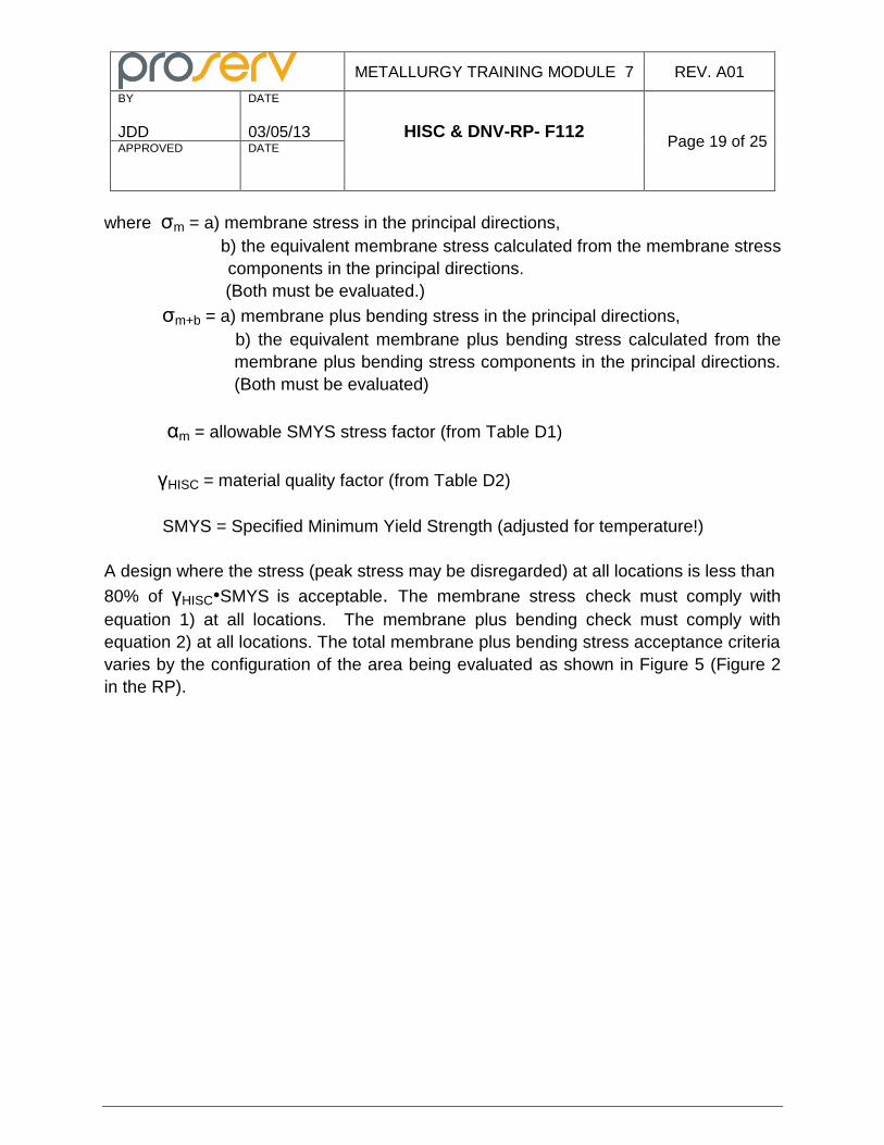
where σm = a) membrane stress in the principal directions,
b) the equivalent membrane stress calculated from the membrane stress
components in the principal directions.
(Both must be evaluated.)
σm+b = a) membrane plus bending stress in the principal directions,
b) the equivalent membrane plus bending stress calculated from the
membrane plus bending stress components in the principal directions.
(Both must be evaluated)
αm = allowable SMYS stress factor (from Table D1)
γHISC = material quality factor (from Table D2)
SMYS = Specified Minimum Yield Strength (adjusted for temperature!)
A design where the stress (peak stress may be disregarded) at all locations is less than
80% of γHISC•SMYS is acceptable. The membrane stress check must comply with
equation 1) at all locations. The membrane plus bending check must comply with
equation 2) at all locations. The total membrane plus bending stress acceptance criteria
varies by the configuration of the area being evaluated as shown in Figure 5 (Figure 2
in the RP).
METALLURGY TRAINING MODULE 7 REV. A01
BY
JDD
DATE
03/05/13 HISC & DNV-RP- F112
Page 20 of 25 APPROVED
DATE
Figure 5: Membrane Plus Bending Stress Criteria
This figure illustrates the criteria given in Table D1in the RP (given below).
METALLURGY TRAINING MODULE 7 REV. A01
BY
JDD
DATE
03/05/13 HISC & DNV-RP- F112
Page 21 of 25 APPROVED
DATE
It is obvious from the above that the geometry of weld neck flanges is extremely
important in preventing HISC. A poorly designed weld neck hub flange was a major
contributing factor in the Foinaven failure.
As we’ve previously discussed, a microstructure with fine austenite spacing is more
HISC resistant than one with coarse spacing. The RP makes an allowance for this in
the stress criteria by allowing a higher HISC material factor, γHISC, for fine austenite
spacing (100%) than for coarse spacing (85%) in Table D2. Austenite spacing
characterization will be addressed more fully in Section 5 of the RP, Materials, and in
Section 7, Procedure for Assessment of Austenite Spacing.
If the stress fails to meet the prescribed limits, then the RP gives the following options.
1. A more detailed assessment of the component can be made
2. The non-linear strain criteria may be invoked
3. The component may have to be redesigned to lower stresses.
Stress components parallel to a weld can be considered outside of Lres, this does not
apply to the equivalent stress.
Sub-section E of Section 4 prescribes the non-linear strain criteria that may be used as
an alternative to the linear elastic stress criteria we just covered. It is based upon
limiting loads so that significant cold creep and HISC do not occur in the material. Cold
creep
facilitates the entry of hydrogen into the material and greatly increases the risk of HISC.
This approach requires that a non-linear finite element analysis (FEA) be run using a
non-linear material hardening description. Creep strain should not be included in the
non-linear strain evaluation. The calculations must consider misalignment, geometric
transitions, and welds. The FEA must have sufficient through-thickness mesh
refinement to capture the relevant strain gradients. The material hardening curve used
in the calculations shall have the SMYS and strain hardening curve adjusted for the
highest design temperature.
The material hardening curve may have the following characteristics:
Linear elastic to 0.1% total strain
METALLURGY TRAINING MODULE 7 REV. A01
BY
JDD
DATE
03/05/13 HISC & DNV-RP- F112
Page 22 of 25 APPROVED
DATE
80% of SMYS corresponds to 0.3% total strain
SMYS corresponds to 0.5% total strain
An appropriate curve should describe the strain hardening after 0.5% strain
The RP allows the use of stress/strain data by tensile tests from the actual component
material type if sufficient tests have been run to statistically account for variations.
Neuber’s rule may be used to approximate strain concentrations in a component when
the linear stress criteria aren’t met. Neuber’s rule can be stated as follows:
Kt2•S•e = σ • ϵ
Where Kt = elastic stress concentrator
S and E = nominal stress and strain (excluding SCF)
σ and ϵ = local stress and strain (including SCF)
The results must meet Table E1 in the RP (given below).
METALLURGY TRAINING MODULE 7 REV. A01
BY
JDD
DATE
03/05/13 HISC & DNV-RP- F112
Page 23 of 25 APPROVED
DATE
SECTION 5 – MATERIALS
This section of the RP gives guidance on the use of duplex stainless steels: limitations and general requirements, quality control to insure sound material, and processing suggestions that will improve their HISC resistance. The RP applies to both 22Cr (standard) and 25Cr (super) duplex stainless steels. It references the following UNS numbers: 22Cr – S31803, S32205 25Cr – S32550, S32750, S32760 There are new grades of duplex stainless steels being introduced all the time. If you want to use a new grade that is outside of the composition limits of these UNS numbers, the RP states that qualification (HISC resistance) testing may need to be carried out. The provisions of the RP are based primarily on field data from equipment that was designed to a SMYS. It therefore limits the room temperature SMYS of 22CR DSS to 450MPa (65.3ksi) maximum and 550MPa (80.0ksi) maximum for 25Cr. Using higher strengths may require qualification (HISC resistance) testing. The SMYS of welds is assumed to be equal to that of the base material. The RP assumes the material is in
METALLURGY TRAINING MODULE 7 REV. A01
BY
JDD
DATE
03/05/13 HISC & DNV-RP- F112
Page 24 of 25 APPROVED
DATE
the solution annealed condition. DSS intentionally cold worked to enhance mechanical properties is thus outside the scope of the RP.
The material quality factor, γHISC, used in the linear elastic stress evaluation approach
and given in Table D2 is dependent on whether or not the material has a fine or a coarse austenite spacing. The RP states that the following materials can be assumed to have a fine austenitic spacing:
HIP (Hot Isostatic Pressed) materials
Weld metal (but the HAZ is considered having the same spacing as base metal)
Tube and pipe made by extrusion, seamless rolling or drawing. This includes fittings made from such tubulars.
Rolled plate with wall thickness less than 25mm (1”) including pipes and fittings made from such rolled plate.
All other material is assumed to have coarse spacing unless you make actual measurements of the austenite spacing. The procedure for making these measurements is given in Section 7 of the RP. The spacing should always be measured in a plane in which crack propagation is most likely to occur (generally the through-thickness direction). The RP suggests that 30 micrometers be used as the break off point between fine and coarse spacing, but this is subject to agreement. The orientation of the grain flow is very important as previously discussed (see Figure 3). The grain flow within the part should always be oriented parallel to the principal tensile stress whenever possible. Crack growth will be transverse to this direction and will have the shortest ferrite path before encountering the tougher austenite. The RP references DNV-OS-F101, NORSOK M-601, and NORSOK M-630 for the quality control of duplex stainless steels. It notes that there is no agreed upon, standard test for HISC susceptibility of duplex stainless steels.
SECTION 6 – NON-DESTRUCTIVE TESTING
Proper NDT of components made from DSS is a must. The RP states that fracture mechanics testing of DSS components under C/P have given CTOD values consistently below 0.05mm. The presence of defects, especially those open to the surface, can greatly increase the risk HISC. Do not assume that the NDT (or NDE as it is sometimes called) requirements in a given design standard such as API 6A are sufficient for minimizing HISC in DSS. Weldments, butter welds in particular, are highly vulnerable to HISC and require the most thorough non-destructive evaluations possible.
METALLURGY TRAINING MODULE 7 REV. A01
BY
JDD
DATE
03/05/13 HISC & DNV-RP- F112
Page 25 of 25 APPROVED
DATE
Duplex stainless steels have some unique NDT issues associated with them. They are approximately half ferritic and half austenitic. The ferrite phase is ferromagnetic while the austenitic is not. While DSS may be sufficiently ferromagnetic to magnetize to the proper field strength, magnetic particle inspection is impractical as a surface inspection technique because the non-ferromagnetic austenite phase generates a tremendous amount of background noise (like a fine spider web laid over the surface) masking relevant indications. Dye penetrant (also called liquid penetrant inspection) is the preferred surface NDT method. The RP recommends a dwell time of at least 60 minutes before removing the penetrant and applying the developer. Ultrasonic testing (UT) is more complex on DSS than on carbon and low alloy steels because of the duplex microstructure, grain size, and grain flow. The RP recommends following the NDT recommendations in DNV-OS-F101 or EN 10228 for DSS. Both UT and radiographic testing (RT) have their strengths and weaknesses as far as their ability to detect certain types of defects as far as the location, size, and orientation of the defect is concerned. Many design standards such as API 6A that require volumetric NDT of components allows the use either method. The RP suggests that in many cases both techniques should be used as they often complement each other. This is particularly true of NDT of butter welds.