52
Hydrokraft Transmission Closed Loop Piston Pumps Technical Catalog TVX

Hydrokraft Transmission
Closed Loop Piston Pumps
Technical Catalog TVX

2 EATON Vickers Hydrokraft Transmission Piston Pumps V-PUPI-MC001-E March 2003
Table of Contents
Introduction . . . . . . . . . . . . . . . . . . . . . . . . . . . . . . . . . . . . . . . . . . . . . . . . . . . . . . . . . . . . . . . . . . . . . . . 4
Model Codes
Form Page . . . . . . . . . . . . . . . . . . . . . . . . . . . . . . . . . . . . . . . . . . . . . . . . . . . . . . . . . . . . . . . . . . . . . 5
Basic Pump . . . . . . . . . . . . . . . . . . . . . . . . . . . . . . . . . . . . . . . . . . . . . . . . . . . . . . . . . . . . . . . . . . . . 6
ES Control . . . . . . . . . . . . . . . . . . . . . . . . . . . . . . . . . . . . . . . . . . . . . . . . . . . . . . . . . . . . . . . . . . . . . 7
HG Control . . . . . . . . . . . . . . . . . . . . . . . . . . . . . . . . . . . . . . . . . . . . . . . . . . . . . . . . . . . . . . . . . . . . . 8
FE Control . . . . . . . . . . . . . . . . . . . . . . . . . . . . . . . . . . . . . . . . . . . . . . . . . . . . . . . . . . . . . . . . . . . . . 9
DP Control . . . . . . . . . . . . . . . . . . . . . . . . . . . . . . . . . . . . . . . . . . . . . . . . . . . . . . . . . . . . . . . . . . . . 10
SP Control . . . . . . . . . . . . . . . . . . . . . . . . . . . . . . . . . . . . . . . . . . . . . . . . . . . . . . . . . . . . . . . . . . . . 11
Special Features. . . . . . . . . . . . . . . . . . . . . . . . . . . . . . . . . . . . . . . . . . . . . . . . . . . . . . . . . . . . . . . . 12
Combination Units. . . . . . . . . . . . . . . . . . . . . . . . . . . . . . . . . . . . . . . . . . . . . . . . . . . . . . . . . . . . . . 13
Examples for Combination Units . . . . . . . . . . . . . . . . . . . . . . . . . . . . . . . . . . . . . . . . . . . . . . . . . . 14
Pump Specifications
US . . . . . . . . . . . . . . . . . . . . . . . . . . . . . . . . . . . . . . . . . . . . . . . . . . . . . . . . . . . . . . . . . . . . . . . . . . 15
Metric . . . . . . . . . . . . . . . . . . . . . . . . . . . . . . . . . . . . . . . . . . . . . . . . . . . . . . . . . . . . . . . . . . . . . . . . 16
Performance Curves . . . . . . . . . . . . . . . . . . . . . . . . . . . . . . . . . . . . . . . . . . . . . . . . . . . . . . . . . . . . . . . 17
Operating Data. . . . . . . . . . . . . . . . . . . . . . . . . . . . . . . . . . . . . . . . . . . . . . . . . . . . . . . . . . . . . . . . . . . . 18
Hydraulic Transmission Circuit . . . . . . . . . . . . . . . . . . . . . . . . . . . . . . . . . . . . . . . . . . . . . . . . . . . . . . . 19
Controls
FE, HG Manual Adjustment Displacement Control . . . . . . . . . . . . . . . . . . . . . . . . . . . . . . . . . . . . . 20
Electric Motor Displacement Control ES . . . . . . . . . . . . . . . . . . . . . . . . . . . . . . . . . . . . . . . . . . . . . 21
Pressure Signal Displacement Control DP . . . . . . . . . . . . . . . . . . . . . . . . . . . . . . . . . . . . . . . . . . . 22
Example for TVX, DP Control. . . . . . . . . . . . . . . . . . . . . . . . . . . . . . . . . . . . . . . . . . . . . . . . . . . . . . 23
Proportional Valve Displacement Control SP . . . . . . . . . . . . . . . . . . . . . . . . . . . . . . . . . . . . . . . . . 24
Example for TVX, SP Control . . . . . . . . . . . . . . . . . . . . . . . . . . . . . . . . . . . . . . . . . . . . . . . . . . . . . . 25
Pump Dimensions*
TVXS 066/090 ES Control . . . . . . . . . . . . . . . . . . . . . . . . . . . . . . . . . . . . . . . . . . . . . . . . . . . . . . . . 26
TVXS 066/090 HG Control . . . . . . . . . . . . . . . . . . . . . . . . . . . . . . . . . . . . . . . . . . . . . . . . . . . . . . . . 28
TVXS 066/090 FE Control. . . . . . . . . . . . . . . . . . . . . . . . . . . . . . . . . . . . . . . . . . . . . . . . . . . . . . . . . 30
TVXS 066/090 DP Control . . . . . . . . . . . . . . . . . . . . . . . . . . . . . . . . . . . . . . . . . . . . . . . . . . . . . . . . 32
TVXS 066/090 SP Control . . . . . . . . . . . . . . . . . . . . . . . . . . . . . . . . . . . . . . . . . . . . . . . . . . . . . . . . 34
TVXS 130/180 ES Control**. . . . . . . . . . . . . . . . . . . . . . . . . . . . . . . . . . . . . . . . . . . . . . . . . . . . . . . 36
3EATON Vickers Hydrokraft Transmission Piston Pumps V-PUPI-MC001-E March 2003
Table of Contents(cont.)
Pump Dimensions* (cont.)
TVXS 130/180 HG Control** . . . . . . . . . . . . . . . . . . . . . . . . . . . . . . . . . . . . . . . . . . . . . . . . . . . . . . 38
TVXS 130/180 FE Control** . . . . . . . . . . . . . . . . . . . . . . . . . . . . . . . . . . . . . . . . . . . . . . . . . . . . . . . 40
TVXS 130/180 DP Control** . . . . . . . . . . . . . . . . . . . . . . . . . . . . . . . . . . . . . . . . . . . . . . . . . . . . . . 42
TVXS 130/180 SP Control**. . . . . . . . . . . . . . . . . . . . . . . . . . . . . . . . . . . . . . . . . . . . . . . . . . . . . . . 44
* TVXS-250 ask for special drawings. Used only for repleasement.
For new applications please use TVWS
** TVXS –130/180 , for new applications please use TVWS-130/180
SAE 4-Bolt Mounting Pads . . . . . . . . . . . . . . . . . . . . . . . . . . . . . . . . . . . . . . . . . . . . . . . . . . . . . . . 46
Application Data . . . . . . . . . . . . . . . . . . . . . . . . . . . . . . . . . . . . . . . . . . . . . . . . . . . . . . . . . . . . . . . . . . 47
Fluid Recommenations . . . . . . . . . . . . . . . . . . . . . . . . . . . . . . . . . . . . . . . . . . . . . . . . . . . . . . . . . . 48
Application Information. . . . . . . . . . . . . . . . . . . . . . . . . . . . . . . . . . . . . . . . . . . . . . . . . . . . . . . . . . 49

Displacement controls:
ES - Electric motordisplacement controlHG - Handwheeldisplacement control FE - Screw adjustmentcontrol SP - Displacementproportional to electricsignalDP - Displacementproportional to pressuresignal
4 EATON Vickers Hydrokraft Transmission Piston Pumps V-PUPI-MC001-E March 2003
Introduction
• Axial piston pumpswith swashplatedesign for reliableoperation and long life.
• Special design forclosed loopapplication.
• Pressure up to 420bar. Rated speed up to1800 r/min higherspeeds possible.
• Rotating and pressureloaded parts arepressure balanced.
• Oversize shaft andshaft bearings.
• Large charge flowrates for low systemtemperature.
• Wide range ofavailable integratedcharge and pilotpressure pumpcombinations.
• Standard availabletransmission circuitswith integrated valvesand filters to buildcomplete closed loopsystem for charge flowand flushing.
• Fast response times.• For new product
applications use TVW.Use TVX 130-250 forservice replacementonly.
AVAILABLE DISPLACEMENTSIZES
66 ccm90 ccm
AVAILABLE REPLACEMENTUNIT DISPLACEMENT SIZES
130 ccm180 ccm250 ccm
Dimensional information listed in this catalog is subject to change without notice.
Typical Section of Transmission Pump
Housing CylinderBlock
SP-ControlsControlPiston
Shaft
SwashPlate
Piston &Shoe
ValvePlate
ValveBlock
ChargePump
PilotPump

5EATON Vickers Hydrokraft Transmission Piston Pumps V-PUPI-MC001-E March 2003
Model CodeTransmission Pumps
"X" Series
1 2 3 4 5 6 7 8 9 10 11 12 13 14 15 16 17 18 19 20 21 22 23 24 25 26 27
T V X M – 1 R VS A 31 32 33 34 35 36 37 38 39 40 41 42 43 44 45 46 47 48 49 50 51 52 53 54 55
1 0
28 29 30
Form Page
The following 55-digit coding system has beendeveloped to identify all of the configuration optionsfor the "X" Series Transmission pumps. Use thismodel code to specify a unit with the desiredfeatures. All 55-digits must be present whenordering. You may want to photocopy the matrixbelow to ensure that each number is entered in thecorrect box. If adjustments other than the standardsettings (character 47...50) or special features(character 51...53) are needed, please provide theinformation when ordering. At the end of thissection you may need to provide an additional modelcode if a combination unit is needed. In case of acombination unit, each single pump section must bespecified separately using this or other Eaton cataloginformation.
In the model code string below some characters arealready filled out and shown on this and thefollowing pages. For such characters there is nooption available.Explanation for each character can be found asfollows:
CHARACTER PAGE
Basic Pump Model Code 1.....27 6Control Options 28...46 7-11Customer Adjustment Specification 47...50 7-11Special Features 51...53 12Design Number 54...55 12Combination Model Code 1.....39 13
SPECIFY NON STANDARD ADJUSTMENT BELOW
SPECIFY SPECIAL FEATURE BELOW

6 EATON Vickers Hydrokraft Transmission Piston Pumps V-PUPI-MC001-E March 2003
Model Code Transmission Pumps
“X" Series - Basic Pump
Pump
T – Transmission Pump
Displacement
V – Variable displacement
Pump Series
X – “X” Series (was 30 design)
Configuration
S – Single UnitR – Rear Unit
Separator
– – Separator
Displacement Size
066 – 66 cm3/r [4.0 in3/rev]090 – 90 cm3/r [5.5.0 in3/rev]130 – 130 cm3/r [7.9 in3/rev]180 – 180 cm3/r [11.0 in3/rev]250 – 250 cm3/r [15.3 in3/rev]750 – 750 cm3/r [45.8 in3/rev]
Basic standard
M – Metric
Mounting flange
02 – ISO 3019/2 - 125A2HW (66 and 90 cm3/r)
04 – ISO 3019/2 - 160A2HW (130 and 180 cm3/r)
06 – ISO 3019/2 - 200A2HW (250 cm3/r)
Rotation Direction
R – Right hand [CW]L – Left hand [CCW]
Adjustment stop
0 – No adjustment stop4 – Fixed mechanical
Adjustment stop side A5 – Fixed mechanical
Adjustment stop side B6 – Fixed mechanical
Adjustment stop side Aand B
Thru-Drive
Options
0000 – None000A – SAE A000B – SAE B000C – SAE C000P – Pilot pump (8 cm3/r)000T – Charge pump
(~25% of unitdisplacement size)
00TP – Charge pump (~25%of unit displacementsize) and Pilot pump (8 cm3/r)
Main Ports
1 – SAE Port - Metric bolts
Main Port Orientation
R – Radial (side ports)
Main Drive Shaft End
01 – ISO straight key02 – ISO spline
Drive Shaft Seal
Configuration
S – Single shaft seal
Seal Material
V – Viton** Viton is a trademark of E.I. Dupont (other materials available, contact your Eaton Representative)
Yoke Position Indicator
0 – No position indicatorV – Visual position indicatorP – Position sensorM – Position sensor and
visual indicator
Housing surface finish
A – Blue painted
Transmission Circuit
0 – No transmission circuit1 – Block filter, optical dirt
indicator2 – Block, filter, electrical dirt
indicator3 – Block without filter
Zero Position Valve
0 – No Zero Position ValveA – With Zero Position Valve
Add Control Model
Code
Code (characters 28...50) onthe following pages
28
27
26
25
24
23
22
2120
19
18
17161514
13
12
1110
9
876
5
4
3
2
1
2 3 4
T V X * — * * * M * * * * * * * * 1 R * * S V * A * * #
5 186 7 8 9 10 11 12 13 14 15 16 17 19 20 21 22 231 25 2624 27 28

7EATON Vickers Hydrokraft Transmission Piston Pumps V-PUPI-MC001-E March 2003
Control type
ES – Electric motordisplacement control
Displacement
Adjustment Options
M – Electric Motor - fastresponse
N – Electric Motor - mdeiumresponse
P – Electric Motor - slowresponse
Electronic Controls00 – Not required
Yoke Displacement ZoneA – Single side of center “A”C – Over center
Extra Functions
0 – Not available
Pressure Control
Options
0 – Not applicable
Power
Control Options
000000 – Not applicable
Pilot Oil Filter0 – Not required
Fail Safe Valve
0 – Not required
Position Monitoring
A – 4 limit switchesB – 8 limit switchesP – 4 limit switches +
sensorT – 8 limit switches +
sensor
Electric Motor Type
2 – Motor with brake (IP54)3 – Motor without brake
(explosion proof)
Control Voltage of Zero
Position Valve
0 – Not applicableB – 110 AC 50 Hz/
120 AC 60 HzD – 220 AC 50 Hz/
240 AC 60 HzG – 12 VDCH – 24 VDC
Customer
Adjustment Specification
0000 - None
???? - Yes (Final number willbe assigned by Eaton.Specify on tablebelow)
Special Features
Add special featuredescription (characters51...55) on page 12 ifrequired
51
50494847
46
45
44
43
42
414039383736
35
34
33
3231
30
2928
Model Code Transmission Pumps
“X" Series - ES Control
E S * 0 0 * 0 0 0 0 0 0 0 0 0 0 * * * * * * * #
28 4129 30 31 32 33 34 35 36 37 38 39 40 42 43 44 45 46 47 48 49 50 51
CUSTOMER ADJUSTMENT SPECIFICATIONS UNIT STD. SETTING CUSTOMER ADJUSTMENT OPTION REMARKS
All Revolution Adjustments below set at ... rpm 1500 –Pressure Relief Valve Side A bar 350Pressure Relief Valve Side B bar 350Charge Pressure Relief Valve - Size 066 & 090 bar 10 –Charge Pressure Relief Valve - Size 130 & 180 bar 13 –Charge Pressure Relief Valve - Size 250 bar 20 –Flushing (Low) Pressure Relief Valve - Size 066 & 090 bar 5 –Flushing (Low) Pressure Relief Valve - Size 130 & 180 bar 7 –Flushing (Low) Pressure Relief Valve - Size 250 bar 10 –Pilot Pressure bar 60 –Mechanical Adjustment Stop Side A L/min Qmax
Mechanical Adjustment Stop Side B L/min Qmin
Displacement Adjusted to ... L/min -50% Qmax Side APosition Monitoring Switch 1 L/min 0 from APosition Monitoring Switch 2 L/min 95% Qmax Side A > 95% not possiblePosition Monitoring Switch 3 L/min 0 from BPosition Monitoring Switch 4 L/min 95% Qmax Side B > 95% not possiblePosition Monitoring Switch 5 L/min –Position Monitoring Switch 6 L/min –Position Monitoring Switch 7 L/min –Position Monitoring Switch 8 L/min –
Pressure Override Side A & B deleted
Theoretical Response Time (sec) for Zero to Maximum DisplacementSIZE 066/90 130/180 250
f Hz 50 60 50 60 50 60Fast 7 6 18 15 15 13Medium 24 20 35 29 30 25Slow 38 432 54 45 48 40

8 EATON Vickers Hydrokraft Transmission Piston Pumps V-PUPI-MC001-E March 2003
Control type
HG – Hand wheeldisplacement control
Displacement
Adjustment Options
0 – Not applicable
Electronic Controls
00 – Not required
Yoke Displacement Zone
A – Single side of center “A”C – Over center
Extra Functions
0 – Not available
Pressure Control Options
0 – Not applicable
Power
Control Options
000000 – Not applicable
Pilot Oil Filter
0 – Not required
Fail Safe Valve
0 – Not required
Position Monitoring
0 – Not position monitoring
Electric Motor Type
0 – No electric motor
Control Voltage of Zero
Position Valve
0 – Not applicable
Customer
Adjustment Specification
0000 - None
???? - Yes (Final number willbe assigned by Eaton.Specify on tablebelow)
Special Features
Add special featuredescription (characters51...55) on page 12 ifrequired
51
50494847
46
45
44
43
42
414039383736
35
34
33
3231
30
2928
Model Code Transmission Pumps
“X" Series - HG Control
H G 0 0 0 * 0 0 0 0 0 0 0 0 0 0 0 0 0 * * * * #
28 4129 30 31 32 33 34 35 36 37 38 39 40 42 43 44 45 46 47 48 49 50 51
CUSTOMER ADJUSTMENT SPECIFICATIONS UNIT STANDARD SETTING CUSTOMER ADJUSTMENT OPTION REMARKS
All Revolution Adjustments below set at ... rpm 1500 – –Pressure Relief Valve Side A bar 350Pressure Relief Valve Side B bar 350Charge Pressure Relief Valve - Size 066 & 090 bar 10 –Charge Pressure Relief Valve - Size 130 & 180 bar 13 –Charge Pressure Relief Valve - Size 250 bar 20 –Flushing (Low) Pressure Relief Valve - Size 066 & 090 bar 5 –Flushing (Low) Pressure Relief Valve - Size 130 & 180 bar 7 –Flushing (Low) Pressure Relief Valve - Size 250 bar 10 –Displacement Adjusted to... L/min Qmax Side A

9EATON Vickers Hydrokraft Transmission Piston Pumps V-PUPI-MC001-E March 2003
Control type
FE – Screw adjusteddisplacement control
Displacement
Adjustment Options
0 – Not applicable
Electronic Controls
00– Not required
Yoke Displacement Zone
A – Single side of center “A”C – Over center
Extra Functions
0 – Not available
Pressure Control Options
0 – Not applicable
Power
Control Options
000000 – Not applicable
Pilot Oil Filter
0 – Not required
Fail Safe Valve
0 – Not required
Position Monitoring
0 – No position monitoring
Electric Motor Type
0 – No electric motor
Control Voltage of Zero
Position Valve
0 – Not applicable
Customer
Adjustment Specification
0000 - None
???? - Yes (Final number willbe assigned by Eaton.Specify on tablebelow)
Special Features
Add special featuredescription (characters51...55) on page 12 ifrequired
51
50494847
46
45
44
43
42
414039383736
35
34
33
3231
30
2928
Model Code Transmission Pumps
“X" Series - FE Control
F E 0 0 0 * 0 0 0 0 0 0 0 0 0 0 0 0 0 * * * * #
28 4129 30 31 32 33 34 35 36 37 38 39 40 42 43 44 45 46 47 48 49 50 51
CUSTOMER ADJUSTMENT SPECIFICATIONS UNIT STANDARD SETTING CUSTOMER ADJUSTMENT OPTION REMARKS
All Revolution Adjustments below set at ... rpm 1500 – –Pressure Relief Valve Side A bar 350Pressure Relief Valve Side B bar 350Charge Pressure Relief Valve - Size 066 & 090 bar 10 –Charge Pressure Relief Valve - Size 130 & 180 bar 13 –Charge Pressure Relief Valve - Size 250 bar 20 –Flushing (Low) Pressure Relief Valve - Size 066 & 090 bar 5 –Flushing (Low) Pressure Relief Valve - Size 130 & 180 bar 7 –Flushing (Low) Pressure Relief Valve - Size 250 bar 10 –Displacement Adjusted to... L/min Qmax Side A

10 EATON Vickers Hydrokraft Transmission Piston Pumps V-PUPI-MC001-E March 2003
Control type
DP – Pressure signaldisplacement control
Displacement
Adjustment Options
G – Mounting interfaceCetop 3 only
H – Remote port G 1/4J – Proportional relief inc.
electronics K – Proportional relief inc.
electronics &displacement control
Electronic Controls
00 – Not required
Yoke Displacement Zone
A – Single side of center “A”C – Over center
Extra Functions
0 – Not available
Pressure Control Options
0 – Not applicable
Power
Control Options
000000 – Not applicable
Pilot Oil Filter
0 – Not requiredV – Filter with visual
indicatorE – Filter with electronic
indicator
Fail Safe Valve
0 – Not required
Position Monitoring
0 – No position monitoring
Electric Motor Type
0 – No electric motor
Control Voltage of Zero
Position Valve
0 – Not applicableB – 110 AC 50 Hz/
120 AC 60 HzD – 220 AC 50 Hz/
240 AC 60 HzG – 12 VDCH – 24 VDC
Customer
Adjustment Specification
0000 - None
???? - Yes (Final number willbe assigned by Eaton.Specify on tablebelow)
Special Features
Add special featuredescription (characters51...55) on page 12 ifrequired
51
50494847
46
45
44
43
42
414039383736
35
34
33
3231
30
2928
Model Code Transmission Pumps
“X" Series - DP Control
D P * 0 0 * 0 0 0 0 0 0 0 0 * 0 0 0 * * * * * #
28 4129 30 31 32 33 34 35 36 37 38 39 40 42 43 44 45 46 47 48 49 50 51
CUSTOMER ADJUSTMENT SPECIFICATIONS UNIT STANDARD SETTING CUSTOMER ADJUSTMENT OPTION REMARKS
All Revolution Adjustments below set at ... rpm 1500 – –Pressure Relief Valve Side A bar 350Pressure Relief Valve Side B bar 350Charge Pressure Relief Valve - Size 066 & 090 bar 10 –Charge Pressure Relief Valve - Size 130 & 180 bar 13 –Charge Pressure Relief Valve - Size 250 bar 20 –Flushing (Low) Pressure Relief Valve - Size 066 & 090 bar 5 –Flushing (Low) Pressure Relief Valve - Size 130 & 180 bar 7 –Flushing (Low) Pressure Relief Valve - Size 250 bar 10 –Pilot Pressure bar 60 –Mechanical Adjustment Stop Side A L/min Qmax
Mechanical Adjustment Stop Side B L/min Qmin

11EATON Vickers Hydrokraft Transmission Piston Pumps V-PUPI-MC001-E March 2003
Model Code Transmission Pumps
“X" Series - SP Control
Control type
SP – Proportional ValveDisplacement Control
Displacement
Adjustment Options
C – With Cetop 3Proportional valveKDG4V 3
F – With Cetop 5Proportional valve
Electronic Controls
00 – Not required03 – ER 9.3 - 10 (Cetop 3)04 – ER 9.4 - 10 (Cetop 5)
Yoke Displacement Zone
A – Single side of center “A”C – Over center
Extra Functions
0 – Not required
Pressure Control
Options
0 – Not applicable
Power
Control Options
000000 – Not applicable
Pilot Oil Filter
0 – Not requiredV – Filter with visual
indicatorE – Filter with electronic
indicator
Fail Safe Valve
0 – Not required1 – With solenoid valve
Position Monitoring
0 – No position monitoring
Electric Motor Type
0 – No electric motor
Control Voltage of Zero
Position Valve
0 – Not applicableB – 110 AC 50 Hz/
120 AC 60 HzD – 220 AC 50 Hz/
240 AC 60 HzG – 12 VDCH – 24 VDC
Customer
Adjustment Specification
0000 – None
???? – Yes (Final numberwill be assigned byEaton. Specify ontable below)
Special Features
Add special featuredescription (characters51...55) on page 12 ifrequired
51
50494847
46
45
44
43
42
414039383736
35
34
33
3231
30
2928
S P * * * * 0 0 0 0 0 0 0 0 * * 0 0 * * * * * #
28 4129 30 31 32 33 34 35 36 37 38 39 40 42 43 44 45 46 47 48 49 50 51
CUSTOMER ADJUSTMENT SPECIFICATIONS UNIT STD. SETTING CUSTOMER ADJUSTMENT OPTION REMARKS
All Revolution Adjustments below set at ... rpm 1500 – –Pressure Relief Valve Side A bar 350Pressure Relief Valve Side B bar 350Charge Pressure Relief Valve - Size 066 & 090 bar 10 –Charge Pressure Relief Valve - Size 130 & 180 bar 13 –Charge Pressure Relief Valve - Size 250 bar 20 –Flushing (Low) Pressure Relief Valve - Size 066 & 090 bar 5 –Flushing (Low) Pressure Relief Valve - Size 130 & 180 bar 7 –Flushing (Low) Pressure Relief Valve - Size 250 bar 10 –Pilot Pressure bar 60 –Mechanical Adjustment Stop Side A L/min Qmax
Mechanical Adjustment Stop Side B L/min Qmin
Max. Stop by Control Side A L/min 95% Qmax El. Card Adjustment Done by Customer Refer to El. card manual
Max. Stop by Control Side B L/min 95% Qmax El. Card Adjustment Done by Customer Refer to El. card manual
Ramp Time 0 _ A For 100% Stroke sec 0 El. Card Adjustment Done by Customer Refer to El. card manual
Ramp Time A _ 0 sec 0 El. Card Adjustment Done by Customer Refer to El. card manual
Preset Input Signals S1 ... S4 L/min – El. Card Adjustment Done by Customer Refer to El. card manual

12 EATON Vickers Hydrokraft Transmission Piston Pumps V-PUPI-MC001-E March 2003
Model Code Transmission Pumps
"X" Series - Special Features
* * * 1 0
Special Features
000 – None*** – Defined by Eaton
Design Number
10 – Design Number
5554
535251
51 52 53 54 55

13EATON Vickers Hydrokraft Transmission Piston Pumps V-PUPI-MC001-E March 2003
Combination Unit
P – PumpT – Transmission PumpM – Motor
Displacement
F – FilledV – Variable
Pump Series
W – “W” Series (was 30 design)
X – “X” Series (was 20 design)
Combination Unit
C
Separator
First
Displacement cm3/r
066 – 66 cm3/r [4.0 in3/rev]090 – 90 cm3/r [5.5 in3/rev]130 – 130 cm3/r [7.9 in3/rev]180 – 180 cm3/r [11.0 in3/rev]250 – 250 cm3/r [15.3 in3/rev]360 – 360 cm3/r [22.0 in3/rev]500 – 500 cm3/r [30.5 in3/rev]750 – 750 cm3/r [45.8 in3/rev]
First Control Type
00 – No Control (for FixedDisplacement Only)
DF – Pressure CompensatorLR – Power ControlES – Electric Motor ControlHG – Handwheel
Displacement ControlFE – Screw Adjustment
Displacement ControlSM – Servo Adjustment
Displacement Control -Mech Feedback
DP – Pressure SignalDisplacement Control
SP – Proportional ValveDisplacement Control
Second
Displacement cm3/r
066 – 66 cm3/r [4.0 in3/rev]090 – 90 cm3/r [5.5 in3/rev]130 – 130 cm3/r [7.9 in3/rev]180 – 180 cm3/r [11.0 in3/rev]250 – 250 cm3/r [15.3 in3/rev]360 – 360 cm3/r [22.0 in3/rev]500 – 500 cm3/r [30.5 in3/rev]750 – 750 cm3/r [45.8 in3/rev]
Second Control Type
00 – No Control (for FixedDisplacement Only)
DF – Pressure CompensatorLR – Power Control ES – Electric Motor ControlHG – Handwheel
Displacement Control FE – Screw Adjustment
Displacement ControlSM – Servo Adjustment
Displacement Control -Mech Feedback
DP – Pressure SignalDisplacement Control
SP – Proportional ValveDisplacement Control
Third
Displacement cm3/r
000 – Not Required066 – 66 cm3/r [4.0 in3/rev]090 – 90 cm3/r [5.5 in3/rev]130 – 130 cm3/r [7.9 in3/rev]180 – 180 cm3/r [11.0 in3/rev]250 – 250 cm3/r [15.3 in3/rev]360 – 360 cm3/r [22.0 in3/rev]500 – 500 cm3/r [30.5 in3/rev]750 – 750 cm3/r [45.8 in3/rev]
Third Control Type
00 – No Control (for FixedDisplacement Only)
DF – Pressure CompensatorLR – Power ControlES – Electric Motor Control HG – Handwheel
Displacement ControlFE – Screw Adjustment
Displacement ControlSM – Servo Adjustment
Displacement Control -Mech Feedback
DP – Pressure SignalDisplacement Control
SP – Proportional ValveDisplacement Control
Fourth
Displacement cm3/r
000 – Not Required066 – 66 cm3/r [4.0 in3/rev]090 – 90 cm3/r [5.5 in3/rev]130 – 130 cm3/r [7.9 in3/rev]180 – 180 cm3/r [11.0 in3/rev]250 – 250 cm3/r [15.3 in3/rev]360 – 360 cm3/r [22.0 in3/rev]500 – 500 cm3/r [30.5 in3/rev]750 – 750 cm3/r [45.8 in3/rev]
Fourth Control Type
00 – No Control (for FixedDisplacement Only)
DF – Pressure CompensatorLR – Power Control ES – Electric Motor ControlHG – Handwheel
Displacement ControlFE – Screw Adjustment
Displacement Control SM – Servo Adjustment
Displacement Control -Mech Feedback
DP – Pressure SignalDisplacement Control
SP – Proportional ValveDisplacement Control
Assembly
Numbers
HC81 – Defined By Eaton
Assembly Numbers
Defined By Eaton
39383736353433323130
29282726
2524
232221
2019
18 17 16
1514
131211
109
8 7 6
5
4
3
2
1
Model CodeCombination Units
• For a combination oftwo or more units fillout this CombinationModel Code.
• Start with the biggestsize unit for the firstdisplacement.
• For each unit includedin this combination, aseparate model codemust be chosen. Usethe form on page 5.
• Character 26 to 39 willbe P/N of thecombination. Thisnumber will be definedby Eaton and providedin the orderacknowledgement.
• Charge and Pilot Pumpthrough drive optionmust be specified onthe rear unit of thecombination (as aspecial feature).
• Front and middle unitsshall have the throughdrive option of thefollowing unit in thecombination.
2 3 4
* * * C — * * * * * * * * * * * * * * * * * * * *
1 5 186 7 8 9 10 11 12 13 14 15 16 17
26
19 20 21 22 23 24 25
27
H C 8 1 * * * * * * * * * *
28 29 30 31 32 33 34 35 36 37 38 39

14 EATON Vickers Hydrokraft Transmission Piston Pumps V-PUPI-MC001-E March 2003
Model CodeExamples for Combination Units
Example 1: Combination of two closed loop pumps
Model Code Front Unit TVWF-500M08R0000H1R02SVMA20SPC03C00000000E100H000000010
Model Code Rear Unit TVXR-066M02R000001R02SVMA00SPC03C00000000E000H000000010
Model Code Combination Unit TVWC-500SP0660SP0000000000HC81**********
Example 2: Combination of one closed loop - and two open loop pumps(For open loop model code refer to the according catalog)
Mode Code Front Unit TVWF-500M08R0000H1R02SVMA20SPC03C00000000E100H000000010
Model Code Middle Unit PVWM-250M07R00E1R02SV0ADF000A0000000000000000010
Model Code Rear Unit PFXR-130M02R00P1A02SV0A00000A0000000000000000010
Model Code Combination Unit TVWC-500SP250DF1300000000HC81**********

15EATON Vickers Hydrokraft Transmission Piston Pumps V-PUPI-MC001-E March 2003
PumpSpecifications -US
MODEL TVX 066 TVX 090 TVX 130 TVX 180 TVX 250
Design Swashplate - Axial piston pumpType of mounting Flange or foot-mounted. Combination units foot mounted onlyPipe connection SAE/Flange B psi 1" = 6000 1" = 6000 1" = 6000 1" = 6000 1" = 6000
A 1" = 6000 1" = 6000 1" = 6000 1" = 6000 1" = 6000Direction of rotation Clockwise when viewing shaft end of pump
Counterclockwise available on requestSpeed range nmin rpm 150
nmax 1800Installation position Optional, see mounting informationAmbient temperature range min °F -4
max 122 Weight m lb 168 168 348 379 540 Mass of inertia J lb ft2 0.38 0.38 1.068 1.068 3.456
HYDRAULIC CHARACTERISTICS
Nominal pressure (100% duty cycle) pN psi 5000 Input pressure p1min psi 12.5 abs
p1max psi Pressure can be applied to the pump inlet but the sum of p1 and p2 must not exceed the maximum value of 6090psi )
Maximum pressure to DIN 24312 p2max psi 6090 Hydraulic fluid Hydraulic oil to DIN 51524 part 2. Refer to section Application Data-Fluid RecommendationsHydraulic fluid temperature range min °F -13 on startup
max 194 Viscosity range for continuous operation min cSt 10
max cSt 75Maximum permissible start viscosity max cSt 1000Filtering ISO 4406 18/15/13Maximum geometric displacement Vg in3 66 90 130 180 250 Maximum geometric n= 1500 rpm Qg USgpm 28 36 52 71 99 pump flow n= 1800 rpm 32 43 62 86 119 Case pressure pv max psi max 7.2psi over pA, pB
HYDRAULIC CHARACTERISTIC OF CHARGE AND PILOT PUMP
Displacement charge pump Vg Sp in3 0.97 1.4 2.01 2.44 3.91 Charge pressure pN Sp psi 73/145 73/145 102/189 102/189 145/290
Input pressure charge & pilot pump pmin Sp/St psi 11.6 absoluteDisplacement pilot pump Vg St in3 0.5 Pilot pressure pSt psi 870 870 870 870 870
DRIVE
Maximum driving torque - single unit M1 Single lb.ft. 325 443 640 887 1243 (p2 max, η= 100%)
Maximum power consumption - single unit P1 Single hp 93 126 182 254 355 (p2 max, η= 100%; n= 1800 rpm)
Max. driving torque - comb. unit M1 Comb. lb.ft. 2x325 2x443 2x643 2x890 2x1248 1) TVW - 750 at 1800 rpm reduced to 38.1 in3
2) When pressure below 1450psi and flow below 25% of maximum flow

16 EATON Vickers Hydrokraft Transmission Piston Pumps V-PUPI-MC001-E March 2003
PumpSpecifications -Metric
MODEL TVX 066 TVX 090 TVX 130 TVX 180 TVX 250
Design Swashplate - Axial piston pumpType of mounting Flange or foot-mounted. Combination units foot mounted onlyPipe connection SAE/Flange B psi 1" = 6000 1" = 6000 1" = 6000 1" = 6000 1" = 6000
A 1" = 6000 1" = 6000 1" = 6000 1" = 6000 1" = 6000Direction of rotation Clockwise when viewing shaft end of pump
Counterclockwise available on requestSpeed range nmin min-1 150
nmax 1800Installation position Optional, see mounting informationAmbient temperature range min °C -20
max 50Weight m kg 76 76 138 172 245Mass of inertia J kg m2 0.016 0.016 0.045 0.045 0.146
HYDRAULIC CHARACTERISTICS
Nominal pressure (100% duty cycle) pN bar 5000 (350)Input pressure p1min bar 4 abs
p1max bar Pressure can be applied to the pump inlet but the sum of p1 and p2 must not exceed the maximum value of 420 bar
Maximum pressure to DIN 24312 p2max bar 420Hydraulic fluid Hydraulic oil to DIN 51524 part 2. Refer to section Application Data-Fluid RecommendationsHydraulic fluid temperature range min °C -25 on startup
max 90Viscosity range for continuous operation min cSt 10
max cSt 75Maximum permissible start viscosity max cSt 1000Filtering ISO 4406 18/15/13Maximum geometric displacement Vg cm3 4.03 5.49 7.93 10.98 15.26Maximum geometric n= 1500 min-1 Qg L/min 99 135 195 270 375pump flow n= 1800 min-1 L/min 118 162 234 324 450Case pressure pv max bar max 7.2psi (0.5 bar) over air pressure pA, pB
HYDRAULIC CHARACTERISTIC OF CHARGE AND PILOT PUMP
Displacement charge pump Vg Sp cm3 16 23 33 40 64Charge pressure pN Sp bar 5/10 5/10 7/13 7/13 10/20
Input pressure charge & pilot pump pmin Sp/St bar 0,8 absoluteDisplacement pilot pump Vg St cm3 8Pilot pressure pSt bar 60 60 60 60 60
DRIVE
Maximum driving torque - single unit M1 Single Nm 440 600 868 1202 1685(p2 max, η= 100%)
Maximum power consumption - single unit P1 Single kW 69 94 136 189 265(p2 max, η= 100%; n= 1800 min-1)
Maximum driving torque - comb. unit M1 Comb. Nm 2x440 2x600 2x868 2x1202 2x16851) TVW - 750 at 1800 min-1 reduced to 625cm3
2) When pressure below 100 bar and flow below 25% of maximum flow

17EATON Vickers Hydrokraft Transmission Piston Pumps V-PUPI-MC001-E March 2003
PerformanceCurves - 066, 090, 130,180, 250 Series
250
180
130
90
066
Eff
ecti
ve O
utl
et F
low
0 100 200 300 400 bar0
400
0 1000 3000 5000 5800 psi
300
200
100
0
50
100
150
200
L/min
250kW
Operating Pressure
PFX/PVX
0
50
150
200
250
350hp
300
10040
60
80
100
USgpm
20
Th
eore
tica
l Po
wer
Co
nsu
mp
tio
n P
0 100 200 300 400
100
50
0 1000 2000 3000 4000 5000 5800
Eff
icie
ncy
(%
)
tot.
vol.
Operating Pressure
90
80
70
60
40
30
20
10
0
tot for 100 % Vg
tot for 50 % Vg
tot for 25 % Vg
Outlet Flow andTheoretical PowerConsumption
Volumetric and OverallEfficiencies
For Calculation: Peff = Pth/ηtotTypical at 1500 min-1 with anti-wear oil at 40 cSt
Single displacement pumps: PFX,PVX
Combination units
For combination pumpsthe characteristic valuesare as for the individualunits.
For reduced swash-angle:
Lh = (L at Vmax) x 1
VVmax
103( )

18 EATON Vickers Hydrokraft Transmission Piston Pumps V-PUPI-MC001-E March 2003
Operating Data066,090,130,180,250 Series
50 100 200 300 400bar
725psi
Basi
c Ra
ting
Life
L10
[h]
1450 2900 4350 5800
3 x 10³
410
510Pump size 066
Operating Pressure
1800 min
1500 min
1000 min-1
-1
-1
50 100 200 300 400bar
725psi
Basi
c Ra
ting
Life
L10
[h]
1450 2900 4350 5800
3 x 10³
410
510Pump size 090
Operating Pressure
1800 min
1500 min
1000 min-1
-1
-1
50 100 200 300 400bar
725psi
Basi
c Ra
ting
Life
L10
[h]
1450 2900 4350 5800
3 x 10 3
410
510Pump size 130
Operating Pressure
1800 min
1500 min
1000 min-1
-1
-1
50 100 200 300 400bar
725psi
Basi
c Ra
ting
Life
L10
[h]
1450 2900 4350 5800
3 x 10 3
410
510Pump size 180
Operating Pressure
1800 min
1500 min
1000 min -1
-1
-1
50 100 200 300 400bar
725psi
Basi
c Ra
ting
Life
L10
[h]
1450 2900 4350 5800
3 x 10 3
410
510Pump size 250
Operating Pressure
1800 min
1500 min
1000 min -1
-1
-1
Theoretical Bearing Life Time
At maximum displacementand various speeds.

19EATON Vickers Hydrokraft Transmission Piston Pumps V-PUPI-MC001-E March 2003
HydraulicTransmissionCircuit“X” Series – Closed Loop
A, B System port
L1, L2, Drain port
L3 Oil filling plug
MA, MB Gauge port-systempressure
MS Gauge port-chargepressure
S Suction port forcharge pump
L Drain port motor
1 Basic pump
2 Charge block
2.1 Charge pump
2.2 Charge pressure reliefvalve
2.3 Charge flow filter
2.4 Clogging indicator forcharge flow filter
2.5 Charge check valves (2 pcs)
2.6 Charge pressure reliefswitch
3 Flushing block
3.1 Low pressure relief valve(replenishing valve)
3.2 Flushing flow shuttlevalve
6 High pressure reliefvalve
9 Servo motor
10 Control limit switches
11 Control feedbackpotentiometer
20 Motor MF
21 Limit switches (speed control)
22 Rearbox
30 Reservoir
31 Cooler Oil/Air
32 Bypass - Valve
33 Thermometer
34 Optical Level Indicator
35 Venting Filter
36 Level switch
37 Temperature switch
38 Electric motor
18 bar
ISO VG 46
12 bar
Motor
70∞C90∞C
Drain
A
B
Drain
minmax
MM
M
38
2.6
2.3
1
2.1
2.5
2.510
11
9
63.2
3.1
2220
21
3033
34
35 36 37 31 32
2.2
2
2.4
3
M1
IIIIIIIV
500 OhmR1 S L1 L1 L2 L3 MB
B
MS MA
A
B L
A
Example for a completedHydraulic Transmission
Example shown is a com-plete drive for a slow speedconveyor belt, with TVX-pump and ES-control, withMF-motor and gearbox, inte-grated in a power unit.

20 EATON Vickers Hydrokraft Transmission Piston Pumps V-PUPI-MC001-E March 2003
FE, HG ManualAdjustmentDisplacementControl“X” Series – Closed Loop
+100%
0 to +V max
-100%
+V
-V
displacement
FE The FE-control is adisplacement controlwhere the pump flow is adjusted by a screw.
HG The HG-control is a displacement controlwhere the pump flowcan be adjusted byhandwheel.
The maximum (and/orminimum) flow can belimited by a spacer insidethe control cylinder(position no. 13 inmodelcoding, options 4, 5or 6 in combination with
customer adjustmentspeculation position 47-50for the set values). Thesetting must be definedbefore ordering andcannot be modifiedduring operation.

21EATON Vickers Hydrokraft Transmission Piston Pumps V-PUPI-MC001-E March 2003
Electric MotorDisplacementControl ES“X” Series – Closed Loop
Response Time Table
THEORETICAL RESPONSE TIME (SEC) FOR MAXIMUM DISPLACEMENT CHARACTER IN MODELCODE POS. 30
Size 066 / 090 130 / 180 250Freq. Hz 50 60 50 60 50 60Fast 7 6 18 15 15 13 MMedium 24 20 35 29 30 25 NSlow 38 32 54 45 48 40 P
Response time from 0 to +Qmax or 0 to - Qmax
Flow
from
AFl
ow fr
om B
100%
100%
servo motorcw
off
ccw0
The unit is used for flowadjustment. It has athree phase electricservo motor, wormgearing and a switch boxwith 4 or (optional) 8limit switches fordifferent positions. Apotentiometer is alsoavailable.
The response timesfrom zero to maximumdepends on the chosenratio and the (fixed)speed of the servomotor (this means thatonce the control isdefined and built theresponse times are notvariable duringoperation).
No Pressure / PowerLimiter possible!Explosion protectionversions are alsoavailable.As an additional optionthe maximum (and/orminimum) flow can belimited by a spacerinside the controlcylinder
(position no. 13 in modelcoding, options 4, 5 or 6in combination withcustomer adjustmentspeculation position47-50 for the set values).The setting must bedefined before orderingand cannot be modifiedduring operation.

22 EATON Vickers Hydrokraft Transmission Piston Pumps V-PUPI-MC001-E March 2003
Pressure SignalDisplacementControl DP“X” Series – Closed Loop
TVX Response Times DP - Control
SIZE RESPONSE TIME (SEC) WITH 12 L/MIN PILOT OIL FLOW
(Standard) Pilot Pressure pSt [bar]
066/090 0,7 60130/180 0,9 60250 1,1 60
+100%
1040 barPilot pressure
30 20
flow
from
B
-100%
Pilot pressure10 20 40 bar30
flow
from
A
The output flow of thepump is proportional tothe pilot pressure.A separate pilot oilcircuit is necessary. From this, the controlpressure is reduced tothe desired set value bymeans of a suitablepressure control valve(with P-T line) andthrottle in P-line 0.8 Ø(0.03 in).
To work in bothdirections, a solenoidvalve is needed to switchthe pilot flow from A toB (pos. 30 in modelcoding, option “K”).The DP-control can beused for stepless flowcontrol with standardrequirements fordynamic and precision.
No feedback signal isneeded, an opticalindicator recommended (pos. 24 in modelcoding, option “V”).A pilot oil filter can bemounted in-line betweenpump and control (pos.42 in model coding,option “V” or “E”).Pressure limiter orpower limiter overridenot available (for suchand other options pleaserefer to PVW-Series).
As an additional optionthe maximum (and/orminimum) flow can belimited by a spacer insidethe control cylinder(position no.13 in modelcoding, options 4, 5 or 6in combination withcustomer adjustmentspeculation position 47-50for the set values). Thesetting must be definedbefore ordering andcannot be modifiedduring operation.
The output flow of the pump is proportional to the pilot pressure
+100%
A T P T A B
P T A B
P T A BP T
M8
D1
Qmax
-100%
pSt
LBS
23EATON Vickers Hydrokraft Transmission Piston Pumps V-PUPI-MC001-E March 2003
Example for TVXSDP Control“X” Series – Closed Loop
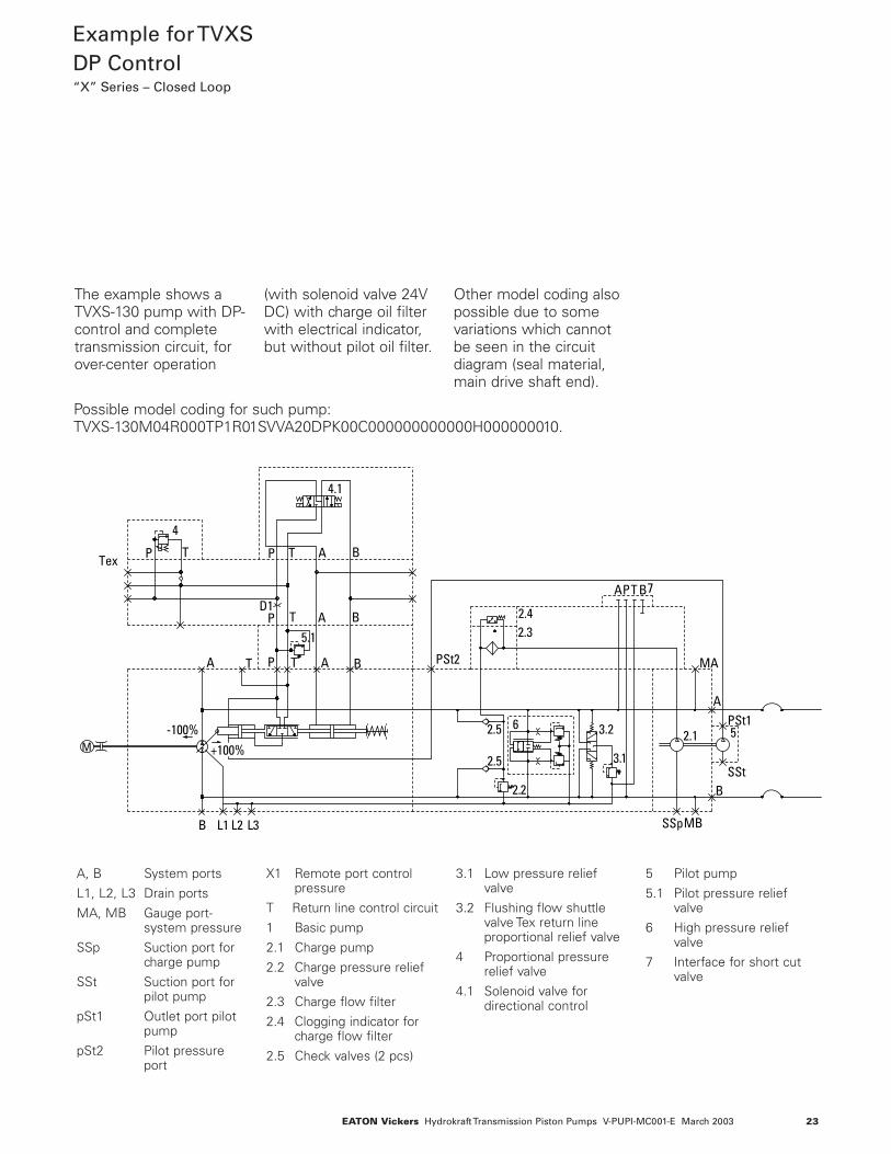
The example shows aTVXS-130 pump with DP-control and completetransmission circuit, forover-center operation
(with solenoid valve 24VDC) with charge oil filterwith electrical indicator,but without pilot oil filter.
Other model coding alsopossible due to somevariations which cannotbe seen in the circuitdiagram (seal material,main drive shaft end).
+100%
A T P T A
P T A
P T AP TTex
D1
-100%M
4
B
B
B
APT B
SSp
B
A
PSt2
PSt1
SSt
MB
MA
2.32.4
2.5
2.5
6
2.2
3.2
3.1
7
L1B L2 L3
2.1 5
4.1
5.1
A, B System ports
L1, L2, L3 Drain ports
MA, MB Gauge port-system pressure
SSp Suction port forcharge pump
SSt Suction port forpilot pump
pSt1 Outlet port pilotpump
pSt2 Pilot pressureport
X1 Remote port controlpressure
T Return line control circuit
1 Basic pump
2.1 Charge pump
2.2 Charge pressure reliefvalve
2.3 Charge flow filter
2.4 Clogging indicator forcharge flow filter
2.5 Check valves (2 pcs)
3.1 Low pressure reliefvalve
3.2 Flushing flow shuttlevalve Tex return lineproportional relief valve
4 Proportional pressurerelief valve
4.1 Solenoid valve fordirectional control
5 Pilot pump
5.1 Pilot pressure reliefvalve
6 High pressure reliefvalve
7 Interface for short cutvalve
Possible model coding for such pump: TVXS-130M04R000TP1R01SVVA20DPK00C000000000000H000000010.

24 EATON Vickers Hydrokraft Transmission Piston Pumps V-PUPI-MC001-E March 2003
The SP control operatesa hydrostatic drive andworks without throttlelosses within electricallyadjustable limits. This isdone by controllingdelivery flow withelectrical swashplateangle feedback(electrical closed-loopcontrol).
All control values arerecorded as an electricalsignal and lead back tothe control card. Theproportional valve andservo piston transformthe output signal of thecontrol card to thedesired setting.This results in a veryprecise and dynamiccontrol.
Pressure limiter overrideavailable on request. Power limiter overridenot available (for suchand other options pleaserefer to TVW series).As an additional optionthe maximum (and/orminimum) flow can belimited by a spacerinside the controlcylinder (position no.13
in model coding, options4, 5 or 6 in combinationwith customeradjustment speculationposition 47-50 for the setvalues). The setting mustbe defined beforeordering and cannot bemodified duringoperation.
ProportionalValveDisplacementControl SP“X” Series – Closed Loop
PROPORTIONAL VALVE
Pilot Pilot Oil Control Response Unit Oil Flow Pressure pSt Electronics Time Size Servo PistonL/min (Amp.card) 0 < > Vmax Diameter Stroke Volume(USgpm) bar (psi) bar (psi) [ms] cm3 mm (in) mm (in) cm3 (in3)
one side per chamberMedium response 12 (3.17) 60 (857) ER 9.3-10 250 066 / 090 40/30 (1.57/1.18) 28 (1.10) 15,4 (0.939)
KDG4V3-2C20NMUH760 12 (3.17) 60 (857) ER 9.3-10 350 130 / 180 55/38 (2.16/1.49) 35 (1.37) 43,5 (2.654)
(CETOP 3) 12 (3.17) 60 (857) ER 9.3-10 550 250 70/50 (2.76/1.97) 43,5 (1.71) 81 (4.942)
High response ON REQUEST(CETOP 5)
The ER9.3-10 and ER 9.4-10 (for high response) digital amplifier cards are optimized for use with the SP-Control. Please ask for separate documentation. Software is available for parameter setting and storing (database function). Contact Eaton to request free of charge manual and software CD.
TVX Response Times SP - Control
TP
BA
L(T)B
A PSt ABT TP10Velectric input signal0
flow
from
Aelectric input signal 010V
flow
from
B
+100 %
-100 %

25EATON Vickers Hydrokraft Transmission Piston Pumps V-PUPI-MC001-E March 2003
Example for TVXSSP Control“X” Series – Closed Loop
4
5.2
5.3
5.1
8.18.1
88
1
2.3
2.4
2.5
2.5
6
2.2
3.2
3.1
2.1 5
7
(XA)
A B
TP
A P T B
L1 SSp
B
PSt AStT BSt
A
PSt2
(XB)
PSt1
SSt
MSt
T
MAMB
L2 MB
MA
L3
M
TP
The example shows aTVXS-130 pump with SP-control, completetransmission circuit andpressure limiter override
for both sides, withcharge and pilot oil filterwith electrical indicator.
Other model coding alsopossible due to somevariations which cannotbe seen in the circuitdiagram (seal material,main drive shaft end).
Note: the below shownpressure limiter overrideis not in standard modelcoding, but will beavailable on request.
Possible model coding for such pump: TVXS-130M04R000TP1R01SVPA20SPC03C30000000E0000000000010.
A, B System ports
L1, L2, L3 Drain ports
MA, MB Gauge port-system pressure
MSt Gauge port-charge pressure
SSp Suction port forcharge pump
SSt Suction port forpilot pump
pSt1 Outlet port pilotpump
pSt2 Pilot pressure port
T Return line controlcircuit
TP Return line pressurelimiter override
1 Basic pump
2.1 Charge pump
2.2 Charge pressure reliefvalve
2.3 Charge flow filter
2.4 Clogging indicator forcharge flow filter
2.5 Charge check valves (2 pcs)
3.1 Low pressure reliefvalve
3.2 Flushing flow shuttlevalve
4 Proportional controlvalve
5 Pilot pump
5.1 Pilot pressure reliefvalve
5.2 Pilot oil filter
5.3 Clogging indicator forpilot oil filter
6 High pressure reliefvalve
7 Interface for short cutvalve
8 Pressure limiteroverride (main stage)
8.1 Pressure limiteroverride (pilot stage)

26 EATON Vickers Hydrokraft Transmission Piston Pumps V-PUPI-MC001-E March 2003
PumpDimensions -TVXS - 066/090ES Control
B
3 optionalorientations3 x 90˚
M12-20 deep Ø25
57.2
27.8
SAE 1", 6000psiPort A/B
Center boreDM12 DIN332
4xM10-20deep
409245.6
150
68.48
26
58
41+0.2
119.6
15390
0
L2
L1
MB
PSp1MSp
L3
35
Ø125 h8
Ø38 k6
10 h9
56
16
111
L3
W40x1,25x10a
Center boreDM12 DIN332 58
68
L1
L1
B
A
Electrical contaminationindicator
Filter
495217.6
PSp1
SSp
-Vmax +Vmax
A, B System pressureport (see detail)
(L1) Drain portM22x1.5/two drainports, one suppliedplugged
L2 M18x1.5x12-deepsupplementary drain,or bleed plug. Mustbe drained in additionto L1 if the pump isinstalled with theshaft input endpointing upwards.
(L3) Oil filling 7/8-14UNF-SAEJ475 or bleedplug. Must be drainedin addition to L1 if thepump is installed withthe shaft input endpointing downwards.
(MA) Gauge port systempressure G 1/4
(MB) Gauge port systempressure G 1/4
(MSp) Gauge port chargepump pressure G 1/4
pSp1 Pressure port ofcharge pump G 1/2
pSp2 Pressure portM22x1.5
SSp Suction port ofcharge pumpG 3/4
(...) Normally plugged
Dimensions in mm
Type ES, Electric MotorDisplacement Control
Control displacement from +Vmax to - Vmax through V0

27EATON Vickers Hydrokraft Transmission Piston Pumps V-PUPI-MC001-E March 2003
PumpDimensions -TVXS - 066/090ES Control
(cont.)
clockwise
High pressurerelief valve
Low pressurerelief valve
257.5
294
122
233
87189
Ø110.5
Ø92
PSp1 PipingSSp
PSp2
Alternativelocation
117.5210
137
180
90A
L1
B
L1
3 optionalorientations3 x 90˚
18
DIRECTION OF ROTATION CONTROL INPUT OUTPUT
Right Hand Rotation To + Vmax B ATo - Vmax A B
Left Hand Rotation To + Vmax A BTo - Vmax B A
28 EATON Vickers Hydrokraft Transmission Piston Pumps V-PUPI-MC001-E March 2003
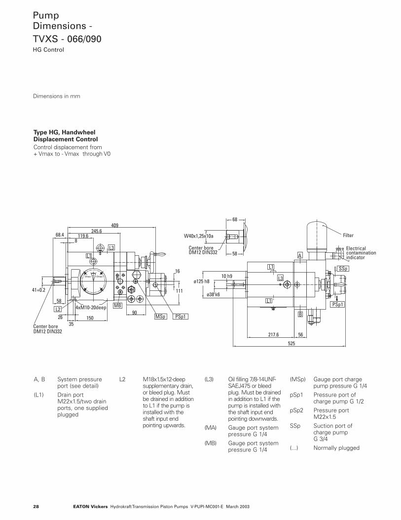
PumpDimensions -TVXS - 066/090HG Control
-Vmax +Vmax
0
L2
L1
MSp
MB
PSp1
L3
409245.6
150
68.48
3526
58
41+0.2
119.6
16
111
904xM10-20deep
DM12 DIN332Center bore
B
W40x1,25x10a
DM12 DIN332Center bore
58
68
L1
L1
PSp1
B
L3
A
SSp
ø125 h8
ø38 k6
10 h9
Electricalcontaminationindicator
Filter
525
217.6 56
Dimensions in mm
Type HG, HandwheelDisplacement Control
Control displacement from + Vmax to - Vmax through V0
A, B System pressureport (see detail)
(L1) Drain portM22x1.5/two drainports, one suppliedplugged
L2 M18x1.5x12-deepsupplementary drain,or bleed plug. Mustbe drained in additionto L1 if the pump isinstalled with theshaft input endpointing upwards.
(L3) Oil filling 7/8-14UNF-SAEJ475 or bleedplug. Must be drainedin addition to L1 if thepump is installed withthe shaft input endpointing downwards.
(MA) Gauge port systempressure G 1/4
(MB) Gauge port systempressure G 1/4
(MSp) Gauge port chargepump pressure G 1/4
pSp1 Pressure port ofcharge pump G 1/2
pSp2 Pressure portM22x1.5
SSp Suction port ofcharge pumpG 3/4
(...) Normally plugged

29EATON Vickers Hydrokraft Transmission Piston Pumps V-PUPI-MC001-E March 2003
PumpDimensions -TVXS - 066/090HG Control
(cont.)
PSp1 PipingSSp
PSp2
87294
248
189
ø92
High pressurerelief valve
relief valveLow pressure
Port A/B
L1
clockwise
L1
SAE 1", 6000psi
27.8
57.2
ø25
117.5210
180
116
M12-20 deep
137
90
18
DIRECTION OF ROTATION CONTROL INPUT OUTPUT
Right Hand Rotation To + Vmax B ATo - Vmax A B
Left Hand Rotation To + Vmax A BTo - Vmax B A

30 EATON Vickers Hydrokraft Transmission Piston Pumps V-PUPI-MC001-E March 2003
PumpDimensions -TVXS - 066/090FE Control
-Vmax +Vmax0
L2
L1
MSp
MB
PSp1
L3
409245.6
150
68.48
3526
58
41+0.2
119.6
16
111
90
Center boreDM12 DIN332 4xM10-20deep
B
L1
L1
BPSp1
L3
A
SSp
Ø125 h8
Ø38 k6
10 h9
Electrical contaminationindicator
Filter
524.8
217.6 56
Dimensions in mm
Type FE, ScrewAdjustmentDisplacement Control
Control displacement from + Vmax to - Vmax through V0
A, B System pressureport (see detail)
(L1) Drain portM22x1.5/two drainports, one suppliedplugged
L2 M18x1.5x12-deepsupplementary drain,or bleed plug. Mustbe drained in additionto L1 if the pump isinstalled with theshaft input endpointing upwards.
(L3) Oil filling 7/8-14UNF-SAEJ475 or bleedplug. Must be drainedin addition to L1 if thepump is installed withthe shaft input endpointing downwards.
(MA) Gauge port systempressure G 1/4
(MB) Gauge port systempressure G 1/4
(MSp) Gauge port chargepump pressure G 1/4
pSp1 Pressure port ofcharge pump G 1/2
pSp2 Pressure portM22x1.5
SSp Suction port ofcharge pumpG 3/4
(...) Normally plugged

31EATON Vickers Hydrokraft Transmission Piston Pumps V-PUPI-MC001-E March 2003
PumpDimensions -TVXS - 066/090FE Control
(cont.)
W40x1,25x10a
Center boreDM12 DIN332 58
68
PSp1 SSp
PSp2
294
248
18987
Ø92
High pressurerelief valve
Low pressurerelief valve
Piping
Port A/B
L1
clockwise
L1
SAE 1", 6000psi
117.5210
137
180
90
M12-20 deep
27.8
57.2
Ø25
18
DIRECTION OF ROTATION CONTROL INPUT OUTPUT
Right Hand Rotation To + Vmax B ATo - Vmax A B
Left Hand Rotation To + Vmax A BTo - Vmax B A

32 EATON Vickers Hydrokraft Transmission Piston Pumps V-PUPI-MC001-E March 2003
PumpDimensions -TVXS - 066/090DP Control
0
W40x1,25x10a
L2
-Vmax +Vmax
L1
PSp1
MB
MSp
L3 T
PSt1
Center boreDM12 DIN332
4xM10-20deep
B
Pilot pressurerelief valve
Adapter plate
Direction valve
Proportional valve609.5
424471
409
245.6
150
41+0
.2
3526
58
119.668.4
104
90
Center boreDM12 DIN332 58
68
L1
L3
L1 SSt
PSt1
B
PSt2
PSp1
T
A
SSp
217.6
Ø125
h8
Ø38
k6
10 h
9
56
111
1
Dimensions in mm
Type DP, Pressure SignalDisplacement Control
Control displacement from+ Vmax to - Vmax throughV0, with internal mechanicalfeedback
A, B System pressureport (see detail)
(L1) Drain portM22x1.5/two drainports, one suppliedplugged
L2 M18x1.5x12-deepsupplementary drain,or bleed plug. Mustbe drained in additionto L1 if the pump isinstalled with theshaft input endpointing upwards.
(L3) Oil filling 7/8-14UNF-SAEJ475 or bleedplug. Must be drainedin addition to L1 if thepump is installed withthe shaft input endpointing downwards.
(MA) Gauge port systempressure G 1/4
(MB) Gauge port systempressure G 1/4
(MSp) Gauge port chargepump pressure G 1/4
pSt1 Pilot pump outletport G 1/2
pSt2 Pilot pressure portM14x1.5
pSp1 Pressure port ofcharge pump G 1/2
pSp2 Pressure portM22x1.5
SSp Suction port ofcharge pumpG 3/4
SSt Suction port of pilotpump G 3/4
T Return line ofcontrol circuit G 1/2
TEX Return line Prop.valve G 1/2
(...) Normally plugged

33EATON Vickers Hydrokraft Transmission Piston Pumps V-PUPI-MC001-E March 2003
PumpDimensions -TVXS - 066/090DP Control
(cont.)
clockwise
18
TEX
TEX
X
View X
PSp1
PSp2
SSp
Low pressurerelief valve
High pressurerelief valve
Piping
118
87294
127
111
248
189
88
Ø92
Port A/B
L1 L1
M12-20 deep
230.5100
117.5210
90
180
137
SAE 1", 6000psi
57.2
27.8
Ø25
DIRECTION OF ROTATION CONTROL INPUT OUTPUT
Right Hand Rotation To + Vmax B ATo - Vmax A B
Left Hand Rotation To + Vmax A BTo - Vmax B A

34 EATON Vickers Hydrokraft Transmission Piston Pumps V-PUPI-MC001-E March 2003
PumpDimensions -TVXS - 066/090SP Control
Filter with electricalcontamination
Pilot pressurerelief valve
indicator
Proportional valve
589471
328409
245.6119.6
150
41+0.2
58
3526
68.48
1611
1
93
904xM10-20deep
Center boreDM12 DIN332
B-Vmax +Vmax0
L2
L1
217.6
Ø125
h7
Ø38
k6
10 h
9
56
FilterElectrical contaminationindicator
L1
L1
PSp1
SSp
B
L3
A
SSt
PSt1MB
MSp
L3
PSp1 PSt1
MStPSt2
130 173
Dimensions in mm
Type SP, ProportionalValve DisplacementControl
Control displacement from + Vmax to - Vmax V0, withposition feedback (viapotentiometer) of swashplate
A, B System pressureport (see detail)
(L1) Drain portM22x1.5/two drainports, one suppliedplugged
L2 M18x1.5x12-deepsupplementary drain,or bleed plug. Mustbe drained in additionto L1 if the pump isinstalled with theshaft input endpointing upwards.
(L3) Oil filling 7/8-14UNF-SAEJ475 or bleedplug. Must be drainedin addition to L1 if thepump is installed withthe shaft input endpointing downwards.
(MA) Gauge port systempressure G 1/4
(MB) Gauge port systempressure G 1/4
(MSt) Gauge port pilotpressure G 1/4
(MSp) Gauge port chargepump pressure G 1/4
pSt1 Pilot pump outletport G 1/2
pSt2 Pilot pressure portG 1/2
pSp1 Pressure port ofcharge pump G 1/2
pSp2 Pressure portM22x1.5
SSp Suction port ofcharge pumpG 3/4
SSt Suction port of pilotpump G 3/4
T Return line ofcontrol circuit G 1/2
(...) Normally plugged
35EATON Vickers Hydrokraft Transmission Piston Pumps V-PUPI-MC001-E March 2003
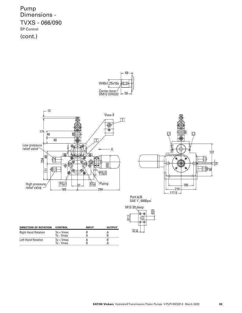
PumpDimensions -TVXS - 066/090SP Control
(cont.)
189
8825
411
1
294
Ø92
87High pressurerelief valve
Low pressurerelief valve
Piping
View X
PSp1
48
40
174
12
SSp
PSp2
X
T
T
W40x1,25x10a
Center boreDM12 DIN332 58
68
SAE 1", 6000psi
57.2
Ø25
27.8
90
137
180210
117.5
M12-20 deep
Port A/B
clockwise
L1 L1
18
DIRECTION OF ROTATION CONTROL INPUT OUTPUT
Right Hand Rotation To + Vmax B ATo - Vmax A B
Left Hand Rotation To + Vmax A BTo - Vmax B A

36 EATON Vickers Hydrokraft Transmission Piston Pumps V-PUPI-MC001-E March 2003
PumpDimensions -TVXS - 130/180 ES Control
B
26deep4xM12
-Vmax+Vmax
0
3 optional orientations3 x 90˚
L2 MB
L1
SSp
L3
MSp
92092
53.5
4032
82
185
148229
306 175,5100 Electro Motor
displacement control
Filter
Contaminationindicator
L1
B
L3
L1
A
SSp
ø50 k6
ø160 h8
271
14 h9
670
70
DM16 DIN332Center bore
487
Dimensions in mm
Type ES, Electric MotorDisplacement Control
Control displacement from+ Vmax to - Vmax through V0
A, B System pressureport (see detail)
(L1) Drain portM26x1.5/two drainports, one suppliedplugged
L2 M18x1.5x12-deepsupplementary drain,or bleed plug. Mustbe drained in additionto L1 if the pump isinstalled with theshaft input endpointing upwards.
(L3) Oil filling 1-1/16-12UNF SAEJ475 orbleed plug. Must bedrained in addition toL1 if the pump isinstalled with theshaft input endpointing downwards.
(MA) Gauge port systempressure G 1/4
(MB) Gauge port systempressure G 1/4
(MSp) Gauge port chargepump pressure G 1/4
SSp Suction port ofcharge pump SAE 1”,3000psi/500psi
(...) Normally plugged

37EATON Vickers Hydrokraft Transmission Piston Pumps V-PUPI-MC001-E March 2003
PumpDimensions -TVXS - 130/180ES Control
(cont.)
Low pressurerelief valve
relief valveHigh pressure
MB
SSp
L1
MA
A
L1
B327
186130
77
74
330
ø92
12 deep
3 optional orientations Alternative
location
L2
A
L1
B
L1
140
368,5
22
ø110.5
288,5
M18x1.5
265260
200224
113
117165
Center boreDM16 DIN332 68
W50x1,25x10a
78 M14-22 deep M12-20 deep
M10-20 deep
Port SSpSAE 1", 3000psi
SAE 1 1/4", 6000psi SAE 1", 6000psiPort A/B, SIZE 180 Port A/B, SIZE 130
66.7
31.8 27.8
57.2
ø32 ø25
26.2
52.4
ø25
clockwise
DIRECTION OF ROTATION CONTROL INPUT OUTPUT
Right Hand Rotation To + Vmax B ATo - Vmax A B
Left Hand Rotation To + Vmax A BTo - Vmax B A

38 EATON Vickers Hydrokraft Transmission Piston Pumps V-PUPI-MC001-E March 2003
PumpDimensions -TVXS - 130/180HG Control
L1
670271 70
Center boreDM16 DIN332
Center boreDM16 DIN332
4xM1226deep
B+Vmax-Vmax
0
Filter
Contaminationindicator
9220
148
53.5+0.2
L2 MB MSp
L3
SSp
487306
229
185
823240
L1
B
L3
L1
A
SSp
Ø160 h8 14 h9Ø50 k6
68
78
W50x1,25x10a
9
Dimensions in mm
Type HG, HandwheelDisplacement Control
Control displacement from+ Vmax to - Vmax through V0
A, B System pressureport (see detail)
(L1) Drain portM26x1.5/two drainports, one suppliedplugged
L2 M18x1.5x12-deepsupplementary drain,or bleed plug. Mustbe drained in additionto L1 if the pump isinstalled with theshaft input endpointing upwards.
(L3) Oil filling 1-1/16-12UNF SAEJ475 orbleed plug. Must bedrained in addition toL1 if the pump isinstalled with theshaft input endpointing downwards.
(MA) Gauge port systempressure G 1/4
(MB) Gauge port systempressure G 1/4
(MSp) Gauge port chargepump pressure G 1/4
SSp Suction port ofcharge pump SAE 1”,3000psi/500psi
(...) Normally plugged

39EATON Vickers Hydrokraft Transmission Piston Pumps V-PUPI-MC001-E March 2003
PumpDimensions -TVXS - 130/180HG Control
(cont.)
Low pressurerelief valve
High pressurerelief valve
MB
SSp
L1
MA
A
L1
B
283
330
77
186130
74
ø92
L2
A
L1 L1
B
140
117
113
265
224
260
200
22
SAE 1", 3000psi/500psi
26.2
52.4
M10-20 deepØ25
Port SSp
57.2
Port A/B, SIZE 130SAE 1", 6000psi
M12-20 deep
31.8
66.7
Ø32
Port A/B, SIZE 180SAE 1 1/4", 6000psi
M14-22 deep
27.8
Ø25
clockwise
M18-12 deep
DIRECTION OF ROTATION CONTROL INPUT OUTPUT
Right Hand Rotation To + Vmax B ATo - Vmax A B
Left Hand Rotation To + Vmax A BTo - Vmax B A

40 EATON Vickers Hydrokraft Transmission Piston Pumps V-PUPI-MC001-E March 2003
PumpDimensions -TVXS - 130/180FE Control
4xM1226deep
Center boreDM16 DIN332
+Vmax-Vmax0
B
487306
148229
L2
L1
MB SSp
L3
92
9
MSp
20
185
3240
53.5
+0.2
Center boreDM16 DIN332
Filter
Contaminationindicator
L1
L3
68
L1
A
B
W50x1,25x10a
78
SSp
670271
Ø160
h8
14 h
9Ø5
0 k6
Dimensions in mm
Type FE, ScrewAdjustmentDisplacement Control
Control displacement from+ Vmax to - Vmax through V0
A, B System pressureport (see detail)
(L1) Drain portM26x1.5/two drainports, one suppliedplugged
L2 M18x1.5x12-deepsupplementary drain,or bleed plug. Mustbe drained in additionto L1 if the pump isinstalled with theshaft input endpointing upwards.
(L3) Oil filling 1-1/16-12UNF SAEJ475 orbleed plug. Must bedrained in addition toL1 if the pump isinstalled with theshaft input endpointing downwards.
(MA) Gauge port systempressure G 1/4
(MB) Gauge port systempressure G 1/4
(MSp) Gauge port chargepump pressure G 1/4
SSp Suction port ofcharge pump SAE 1”,3000psi/500psi
(...) Normally plugged

41EATON Vickers Hydrokraft Transmission Piston Pumps V-PUPI-MC001-E March 2003
PumpDimensions -TVXS - 130/180FE Control
(cont.)
M18-12 deep
Low pressurerelief valve
High pressurerelief valve
L1
MB
SSp
MA
A
L1
SAE 1", 3000psi/500psi
57.2
Port A/B, SIZE 130SAE 1", 6000psi
M12-20 deep
26.2
31.8
66.7
Ø32
Port A/B, SIZE 180SAE 1 1/4", 6000psi
M14-22 deep
52.4
M10-20 deepØ25
27.8
Ø25
Port SSp
A
L2
B
L1 L1
140
clockwise
B
283
330
77
186130
74
265260
22
Ø92
113
224200
117
DIRECTION OF ROTATION CONTROL INPUT OUTPUT
Right Hand Rotation To + Vmax B ATo - Vmax A B
Left Hand Rotation To + Vmax A BTo - Vmax B A

42 EATON Vickers Hydrokraft Transmission Piston Pumps V-PUPI-MC001-E March 2003
PumpDimensions -TVXS - 130/180DP Control
Center boreDM16 DIN332
DM16 DIN332
0-Vmax +Vmax
B
Pilot pressurerelief valve
Adapter plate
Direction valve
Proportional valve
53+0.2
36
431185
612.5487
306229
14820
16
12846
88
L2MB
MSp SSp PSt1
B
L1
L1
T
A
PSt2L3
SSp
L1
TL3
68
683
14h9
Ø50 k6
Ø160 h8
3240
9
34127192
Dimensions in mm
Type DP, Pressure SignalDisplacement Control
Control displacement from+ Vmax to - Vmax throughV0, with internal mechanicalfeedback
A, B System pressureport (see detail)
(L1) Drain portM26x1.5/two drainports, one suppliedplugged
L2 M18x1.5x12-deepsupplementary drain,or bleed plug. Mustbe drained in additionto L1 if the pump isinstalled with theshaft input endpointing upwards.
(L3) Oil filling 1-1/16-12UNF SAEJ475 orbleed plug. Must bedrained in addition toL1 if the pump isinstalled with theshaft input endpointing downwards.
(MA) Gauge port systempressure G 1/4
(MB) Gauge port systempressure G 1/4
(MSp) Gauge port chargepump pressure G 1/4
pSt1 Pilot pump outletport G 1/2
pSt2 Pilot pressure portM16x1.5
SSp Suction port ofcharge pumpSAE 1”,3000psi/500psi
SSt Suction port of pilotpump G 3/4
T Return line ofcontrol circuit G 1/2
Tex Return line Prop.valve G 1/4
(...) Normally plugged

43EATON Vickers Hydrokraft Transmission Piston Pumps V-PUPI-MC001-E March 2003
PumpDimensions -TVXS - 130/180DP Control
(cont.)
SAE 1 1/4", 6000psi
SAE 1", 6000psi
SAE 1", 3000psi/500psi
260224200
200
13
M
22
186
113
283223
207
140
160
16
57.2
ø25
ø32
66.7
31.8
27.8
52.4
ø2526.2
ø92
100230.5
330
265
M12-26 deep
DM16 DIN332Center bore
M14-22 deep
M12-20 deep
M10-20 deep
Low pressurerelief valve
relief valveHigh pressure
Electricalcontamination
Filter
indicator
View X
Zero Position Valve
Connecting Face CETOP3can be used for
A BL1L1
MB
W50x1,25x10a
MA
SSp
L1
A
L1
68
78
484.5431
661.6612.5
567
Port A/B, SIZE 180
Port A/B, SIZE 130
Port SSp
SSt
B
clockwiseSSp
PSt1
SSt
TEX
EXT
XEXT
DIRECTION OF ROTATION CONTROL INPUT OUTPUT
Right Hand Rotation To + Vmax B ATo - Vmax A B
Left Hand Rotation To + Vmax A BTo - Vmax B A

44 EATON Vickers Hydrokraft Transmission Piston Pumps V-PUPI-MC001-E March 2003
PumpDimensions -TVXS - 130/180 SP Control
DM16 DIN332Center bore
DM16 DIN332Center bore
M18x1,5 -12 deep
+Vmax-Vmax0
B
Proportional valve
contraminationFilter with electrical
indicator
Pilot pressurerelief valve
W50x1,25x10a
MB
L1
130 173
L3
MSp SSp PSt1
PSt2
MSt
612
ø50 k6ø160 h8
487401
306
229
431
148
185
53+0.2
L1
L1
B
A
68
78
L2
L3
SSpPSt1
SSt
661.5
341
14 h9
3240
929
271
20
Dimensions in mm
Type SP, ProportionalValve DisplacementControl
Control displacement from+ Vmax to - Vmax throughV0, with position feedback(via potentiometer) ofswashplate
A, B System pressureport (see detail)
(L1) Drain portM26x1.5/two drainports, one suppliedplugged
L2 M18x1.5x12-deepsupplementary drain,or bleed plug. Mustbe drained in additionto L1 if the pump isinstalled with theshaft input endpointing upwards.
(L3) Oil filling 1-1/16-12UNF SAEJ475 orbleed plug. Must bedrained in addition toL1 if the pump isinstalled with theshaft input endpointing downwards.
(MA) Gauge port systempressure G 1/4
(MB) Gauge port systempressure G 1/4
(MSt) Gauge port pilotpressure G 1/4
(MSp) Gauge port chargepump pressure G 1/4
pSt1 Pilot pump outletport G 1/2
pSt2 Pilot pressure portG 1/2
SSp Suction port ofcharge pump SAE 1”,3000psi/500psi
SSt Suction port of pilotpump G 3/4
T Return line ofcontrol circuit G 1/2
(...) Normally plugged

45EATON Vickers Hydrokraft Transmission Piston Pumps V-PUPI-MC001-E March 2003
PumpDimensions -TVXS - 130/180SP Control
(cont.)
M12-26 deep
View X
M14-22 deep
M12-20 deep
Port SSp
can be used forConnecting Face CETOP3
M10-20 deep
Zero Position Valve
FilterElectrical contaminationindicator
Low pressurerelief valve
High pressurerelief valve
MB
4840
174
MA
L1L1
A
X
12
SSp
B
T
T
186
113
289223207
330
484.5431
612.5661.6
567
SSt
SAE 1", 3000psi/500psiø25
52.4
26.2
L1A L1 B
140
clockwise
260224200
M18x1.5
60.5
ø92
20
265
Port A/B, SIZE 180
Port A/B, SIZE 130
SAE 1 1/4", 6000psi
SAE 1", 6000psi
27.8
ø25
ø32
31.8
66.7
57.2
13 22
DIRECTION OF ROTATION CONTROL INPUT OUTPUT
Right Hand Rotation To + Vmax B ATo - Vmax A B
Left Hand Rotation To + Vmax A BTo - Vmax B A

46 EATON Vickers Hydrokraft Transmission Piston Pumps V-PUPI-MC001-E March 2003
SAE 4-BoltMounting Pads
SIZE DIM. CODE 62 SERIES
1" 1 1/4"A 25 32 maxB 27,8 31,8C 57,2 66,7D M12 x 18 M14 x 24
TVX 066 Inlet •Outlet •
TVX 090 Inlet •Outlet •
TVX 130 Inlet •Outlet •
TVX 180 Inlet •Outlet •
Thru-drive Shaft Output TorqueMAXIMUM OUTPUT TORQUE, NM (LB.FT)
Pump Size Keyed Shaft Increasing Load Keyed Shaft Increasing Load Splined Shaft066 520 (383) 260 (190) 660 (485)090 520 (383) 260 (190) 660 (485)130 720 (530) 360 (265) 900 (665)180 720 (530) 360 (265) 900 (665)
D
B
ØAC

47EATON Vickers Hydrokraft Transmission Piston Pumps V-PUPI-MC001-E March 2003
Application Data
1
2
check0,2 bar (3psi)
L
L
1
0,2 bar (3psi)check
3
L
L
INSTALLATION POSITION DRAIN PIPING
Shaft pointed upwards
Shaft pointed downwards

48 EATON Vickers Hydrokraft Transmission Piston Pumps V-PUPI-MC001-E March 2003
Application Data -FluidRecommendations
Case Flushing Requirements
A check valve must notbe used in the drainpipe. The drain pipe mustinterminate below the oillevel in the reservoir.For all other conditionswith low pressure <20bar (<300psi) and lowflow (<10% of Qmax)case flushing is required.For operation withspecial fluids HFB andHFC, case flushing isrecommended.
Flushing Flow
Flushing flow via thepump case should be>1% of maximum pumpflow. Maximum flushingflow depends on casepressure.
Notes:• All listed ratings are
based on the use of agood quality fluid.
• Alternative fluids havea reduced tolerance forcontamination overpetroleum-base fluids.Good filtration istherefore critical.
• The pumps will provideexceptional life whenused with a goodquality clean fluid atthe pump ratingsspecified for that fluid.
Fluids
Pumps in the catalog areprimarily designed tooperate withconventional petroleum-based hydraulic oil.Alternative fluids andrestrictions:• Fluid maintenance is
critical to the durabilityof all hydrauliccomponents, andparticularly so withhydraulic pumps. Thisbecomes even more ofa factor whenalternative fluids areused. All types ofalternative fluidsrequire extensivemaintenance in orderto maintain properlevels of watercontent, acidity,viscosity andcontamination.
Fluid Cleanliness
These pumps are ratedfor anti-wear petroleumfluids with acontamination level of18/15/13 per ISO 4406.Operation in fluids withhigher contaminationlevels than this is notrecommended and mayreduce the life of thepump components.Fluids other thanpetroleum, severe
service cycles, ortemperature extremesare cause for adjustmentof these codes. Pleasecontact your Eatonrepresentative for specialduty cyclerecommendations.Eaton pumps, as well asany variabledisplacement pistonpumps, will operate withapparent satisfaction influids up to the ratingspecified here.Experience has shown,however, that pump andhydraulic system life isnot optimized with highfluid contaminationlevels (high ISOcleanliness codes).Proper fluid condition isessential for long andsatisfactory life ofhydraulic componentsand systems. Hydraulicfluid must have thecorrect balance ofcleanliness, materials,and additives forprotection against wearof inclusion of air. Essential information onthe correct methods fortreating hydraulic fluid isincluded in Eatonpublication 561- "VickersGuide to SystemicContamination Control"-
available from your localEaton distributor.In this publication,filtration and cleanlinesslevels for extending thelife of axial piston pumpsand other systemcomponents are listed.Included is an excellentdiscussion of theselection of productsneeded to control fluidcondition.
Ordering Procedure
When ordering pleasespecify full modeldesignation of itemsrequired; see "ModelCodes" section of thiscatalog.Note the following:• Designation of variable
displacement pumpsmust include thesupplementarydesignation of therequired control.
FLUIDS
MAX MAX RECOMMENDED MAX PRESSURE SPEED SEAL OPERATING BEARING
TYPE CLASSIFICATION BAR RPM MATERIAL TEMPERATURE °C LIFE
Oil in Water Emulsion HFAE Not Rated 0%Water in oil Emulsion HFB 250 1800 Fluorocarbon 49 50%Water Glycol HFC 250 1800 Fluorocarbon 49 25%Phosphate Ester HFDR 350/420 1800 Fluorocarbon 66 100%Polyol Ester HFDU 350/420 1800 Fluorocarbon 66 100%

The schematic enclosedshows a typical heavy dutyhydrostatic transmission. Thepump and motor are themain components. The filter,reservoir, heat exchanger andoil lines make up the rest ofthe system.
The function of thesecomponents is describedbelow:
The Pump
The pump generates theflow of high pressure oil. Thetypical transmission employsa variable displacementpump. The variabledisplacement feature allows
the amount of oil pumped tobe varied. And the amount ofoil pumped controls themotor‘s output speed. Forexample, when the pump‘sdisplacement is zero, no oilis pumped and thetransmission‘s output shaftis at rest. Conversely,maximum displacementproduces maximum speed.The direction of highpressure flow can also bereversed; doing so reversesthe direction the output shaftrotates. An external energysource, called the primemover (usally an electricalmotor), turns the input shaftof the pump.
The Motor
The motor uses the highpressure oil flow from thepump to producetransmission output. Thehigh pressure oil comes tothe motor through one of thehigh pressure lines. lt entersthe motor, turns the outputshaft, then returns to thepump. The pump and motorin the drawing are connectedin a closed-loop circuit.
Important:
Remember, the pumpgenerates flow, and the loadon the motor‘s output shaftcauses resistance to thatflow. That resistance to flowis what creates the highpressure. Therefore, the oilflowing in the lines thatconnect the pump and motoris called ”high pressureflow.”
The pump and motor in thedrawing are contained inseparate housings. Thisconfiguration providesmaximum flexibility in designand transmission installation.
49EATON Vickers Hydrokraft Transmission Piston Pumps V-PUPI-MC001-E March 2003
ApplicationInformation
18 bar
ISO VG 46
12 bar
Motor
70∞C90∞C
Drain
A
B
Drain
minmax
MM
M
38
2.6
2.3
1
2.1
2.5
2.510
11
9
63.2
3.1
2220
21
3033
34
35 36 37 31 32
2.2
2
2.4
3
M1
IIIIIIIV
500 OhmR1 S L1 L1 L2 L3 MB
B
MS MA
A
B L
A
Description of ClosedLoop Transmission withElectric MotorDisplacement Control

50 EATON Vickers Hydrokraft Transmission Piston Pumps V-PUPI-MC001-E March 2003
ApplicationInformation(cont.)
The Charge Pump
The charge pump generatesa low pressure oil flow thathas three functions. First, itsupplies a continuous flow ofoil through the pump andmotor cases. This ”caseflow” keeps the transmissioncool. In the drawing, thecase flow goes from themotor to the pump, then tothe heat exchanger and backto the reservoir. Second, thecharge pump keeps the highpressure lines filled. Thisensures that thetransmission remains primedeven after extended periodsof running in neutral. Finally,charge pump flow providesback pressure in the highpressure lines when thetransmission is in forward orreverse. The charge pumpcontains a relief valve thathelps maintain the pressureof the low pressure oil flow.
The charge pump bolts ontothe pump and its input shaftconnects with the input shaftof the pump. The chargepump inlet receives oil fromthe reservoir.
The Valve Block
The valve block contains atwo-sided high pressurerelief valves, a shuttle valveand a charge pressure reliefvalve.The high pressure relief valveprotects the transmissionfrom pressures that are toohigh. The shuttle valve andcharge pressure relief valvedirect excess charge pumpflow into the pumps case.This case flow cools thepump. The valve block boltsdirectly to the pump.
The Heat Exchanger,Reservoir, Filter, and OilLines
The heat exchanger,reservoir, filter and oil linesare all necessary for heavyduty transmission operation.The heat exchanger connectsbetween the case flow outletand the reservoir. lt cools theoil before it enters thereservoir. The heat exchangermust be fitted with a by-passvalve that opens when casedrain pressure gets too high.The by-pass valve isespecially important duringcold starts when the oil isthick. The reservoir supplies asteady flow of oil to thecharge pump inlet. lt alsoprovides room for the oil toexpand as it gets hot and forentrapped air to escape. Thefilter is installed between thecharge pump outlet and thevalve block. lt removescontaminants from the oil.
The oil lines provide passageways for the oil flowingamong the transmissioncomponents. They must bestrong enough to withstandthe pressures generated andmay be rigid or flexible.
Description of Operation
A hydrostatic transmission isa dynamic system thatoperates through a widerange of conditions.Nevertheless, this wideoperating range canconveniently be divided intothree basic modes: neutral,forward and reverse.
The schematics and theiraccompanying explanationswill help you visualize what‘sgoing on inside thetransmission during each ofthe operating modes.
Important: As you study thefollowing flow descriptions,remember that in all modesof operation, the input shaftof the pump is being turnedby an external power source.
Neutral
The hydrostatic transmissionis in neutral when thevariable pump‘sdisplacement is zero. Withzero displacement, no highpressure oil is pumped to themotor and its output shaft isstopped.
Putting the control signal inthe neutral position centersthe swashplate. With theswashplate centered thepistons don‘t reciprocate asthe cylinder barrel is rotatedand no high pressure oil ispumped.
The charge pump, which isconnected to the input shaft,pumps oil in all modes oftransmission operation. Inneutral, it takes cooled,filtered oil from the reservoirand fills the system. Chargepump flow passes throughthe check valves in thepump’s end cover and fills thepump pistons, the highpressure lines and themotor‘s pistons. This oil flowis intended to make up forinternal leakage and keep thecircuit primed.
After the high pressurecircuit has been primed, thecharge pump pressure opensthe charge pressure reliefvalve located in the chargepump. This directs the chargepump flow through the pumpcase and back to thereservoir. This oil flowflushes and cools the pump.
The forward mode and thereverse mode are similar, sothey will be grouped andcalled the forward! reversemode.

51EATON Vickers Hydrokraft Transmission Piston Pumps V-PUPI-MC001-E March 2003
ApplicationInformation(cont.)
Forward/Reverse
The hydrostatic transmissionis in the forward/reversemode when flow in the highpressure circuit causes themotor shaft to rotate.
Flow in the high pressurecircuit is created by tiltingthe pump‘s variableswashplate from its center orneutral, position. With theswashplate tilted, the pistonsreciprocate as the cylinderbarrel rotates and flow isgenerated.
The swashplate may be tiltedto either side of center.Tilting it one way generatesflow that makes thetransmission go forward.And tilting it the other wayreverses flow and the motorshaft rotates in the oppositedirection.
Besides controlling direction,the swashplate angle alsocontrols output speed.Swashplate angle affectsspeed by changing thepump‘s displacement. The
largest swashplate angleproduces the largestdisplacement and the fastestmotor speed.
The Electrical MotorDisplacement Control circuitvaries the swashplate angleby turning a spindle directlyfixed to the servo piston.According to the direction ofrotation of the control motor,the spindle turns and theswashplate is tilt until themotor is switched off (formore detailed explanationsrefer to separate descriptionof the Electrical MotorDisplacement Control).
Charge pump flow that is notused by the control circuitpasses through the endcover check valve into thebw pressure side of the loop.There it provides backpressure to the motorpistons.
The spring centered shuttlevalve, located in the pump‘svalve block, moves to connectthe low pressure side of theloop to the charge pressure
relief valve. When backpressure gets high enoughthe charge pressure reliefvalve, in the valve block,opens and charge pump flowenters the the pump case.
Case flow flushes the pumpcases and helps keep thetransmission cool. Thecharge pressure relief valvetypically has a lower settingthan the charge pressurerelief valve in the chargepump. This is so case flowwill begin at the motor, go tothe pump, and return to thereservoir.
The charge pressure reliefvalve in the charge pumpopens when thetransmission is in neutral andthe shuttle valve is centered.
The 2-side high pressurerelief valve opens to connectthe high pressure side of theloop to the low pressure sideif the motor stalls and thepressure gets too high. Thisvalve works in forward and inreverse direction.
Last remark
All valves, relief valves andswitches, are adjusted at thetest bench accordingcustomers specification andneeds and must not bemisplaced without specialknowlegde of the hydraulicsystem!

Eaton14615 Lone Oak RoadEden Prairie, MN 55344USATel: 952 937-9800Fax: 952 974-7722www.hydraulics.eaton.com
Eaton20 Rosamond RoadFootscrayVictoria 3011AustraliaTel: (61) 3 9319 8222Fax: (61) 3 9318 5714
EatonDr.-Reckeweg-Str.1 D-76532 Baden-BadenGermanyTel: +49 (07221) 682-0Fax: +49 (07221) 682-788
© 2003 Eaton CorporationAll rights reserved Printed in USADocument No. V-PUPI-MC001-E March 2003


