HYDRO FIELD STATIC DRIVE IN RENEWABLE ENERGY Yoshikazu Homma* and Takahiro Urai* * Industrial Application Engineering Department Bosch Rexroth Corporation 5-1 Higashi-nakanuki Tsuchiura-shi Ibaraki-ken 300-8588 Japan (E-mail: [email protected]) ABSTRACT People are facing up to the problem of the increasing energy supply demand and but request decreasing greenhouse gases. The take off the renewable energy is necessary to satisfy the both requirements. Wind energy and ocean energy is useful energy in development. The drive train of the power take off should be improved. The conventional drive train is usually mechanical transmission. Hydrostatic drive system is a useful power take off system. In this paper some references and the development of hydrostatic drive system are introduced. KEY WORDS No frequency converter, Damping characteristics, Efficiency, Reliability, Over load protection INTRODUCTION Hydrostatic drive system is a reliable long time proofed system. It is able to cover wide power range and speed range. Consequently, hydrostatic drive system is useful to drive the generator of Wind/Current/Tidal turbine, and wave generator. In this paper, some reference and development of Wind/Current/Tidal turbine generators are described. In the second part of this paper, some reference and development of wave generator are described. 1 Wind/Current/Tidal turbine generator The turbine driven by wind or water flow is rotated in low speed (Only a very small wind turbine turns at even 50min -1 ). The standard solution of generation needs to drive the generator in high speed (more than 1000min -1 ). 1.1 Conventional mechanical transmission The conventional mechanical transmission (Gear box) has to be installed inline between turbine rotor and generator. It is designed to transfer the power of turbine 406
Transcript
HYDRO FIELD STATIC DRIVE IN RENEWABLE ENERGY
Yoshikazu Homma* and Takahiro Urai*
* Industrial Application Engineering Department
Bosch Rexroth Corporation
5-1 Higashi-nakanuki Tsuchiura-shi Ibaraki-ken 300-8588 Japan
People are facing up to the problem of the increasing energy supply demand and but request decreasing greenhouse
gases. The take off the renewable energy is necessary to satisfy the both requirements. Wind energy and ocean energy
is useful energy in development. The drive train of the power take off should be improved. The conventional drive
train is usually mechanical transmission. Hydrostatic drive system is a useful power take off system. In this paper some
references and the development of hydrostatic drive system are introduced.
KEY WORDS
No frequency converter, Damping characteristics, Efficiency, Reliability, Over load protection
INTRODUCTION
Hydrostatic drive system is a reliable long time proofed system. It is able to cover wide power range and speed range. Consequently, hydrostatic drive system is useful to drive the generator of Wind/Current/Tidal turbine, and wave generator. In this paper, some reference and development of Wind/Current/Tidal turbine generators are described. In the second part of this paper, some reference and development of wave generator are described.
1 Wind/Current/Tidal turbine generator
The turbine driven by wind or water flow is rotated in low speed (Only a very small wind turbine turns at even 50min-1). The standard solution of generation needs to drive the generator in high speed (more than 1000min-1). 1.1 Conventional mechanical transmission The conventional mechanical transmission (Gear box) has to be installed inline between turbine rotor and generator. It is designed to transfer the power of turbine
406
rotor to generator with good efficiency at rated power. Figure 1 shows the typical configuration of wind turbine with mechanical transmission.
Figure 1 Configuration of wind turbine with mechanical
ansmission
low of turbine generator with mechanical ansmission.
tr Turbine rotor speed is changed by wind speed variation. General mechanical transmission has one gear ratio. Usually a frequency converter is installed between generator and grid due to this and fed constant frequency electric power to grid. Figure 2 shows the power transmission ftr
Figure 2 Power transmission with mechanical
ansmission and frequency converter
3 shows the ause of failure of existing wind turbine.
tr The mechanical transmission mounted direct on shaft which transfers all forces directly through gearbox and generator. Therefore it is difficult to install an over load limiter into a mechanical transmission. Some failures of the mechanical transmission occur due to this reason.
Especially the electric part is dominating and it is related to power electronics required to convert from power from asynchronous generator to grid. Figurec
Turbine rotor
Mechanical transmission (Gear box)
Generator
Figure 3 Failures of wind turbine
5000~5500kg. Figure 4 hows the example of gearbox.
Figure 4 Gear box for wind turbine generator
.2 Basic of Hydrostatic drive transmission
The traditional concept is also heavier which have impact on structure design. The weight of gear box for 1MW generator input is around
Tower
s
Frequency converter
1 One of the alternative solutions of the power train of turbine generator is the Hydrostatic drive technology. The low speed high displacement hydraulic pump is
407
driven by the turbine and high speed low displacement motor drives the generator. The generator can be synchronous type and directly connected to grid elimination medium voltage transformers. Figure 5
ows the concept of hydrostatic drive transmission.
Figure 5 Concept of hydrostatic drive
s the concept of hydrostatic drive with this rrangement.
Figure 6 Concept hydrostatic drive
ve transmission has good damping haracteristics.
sh
Using the variable displacement motor achieves the constant drive speed of generator. The variable high speed small size motors are available in market so the solution with variable motor is a reasonable selection. Figure 6 showa
of
The intense torque fluctuations impacting on the turbine cause changes in rotation speed of turbine rotor. Compared to the stiffness of a mechanical transmission, the hydrostatic drive transmission has a much lower stiffness because of compression of oil and the low inertia of its components. The elastic modulus of oil is 1.6 kN/mm2 compared to 210kN/mm2 for steel. Consequently, due to the elastic connection of turbine
and generator, the rotation speed of turbine may changes on a small scale. Figure 7 shows the simulation result of dynamic analysis and it is proven by measurement [1]. Hydrostatic dric
Figure 7 Simulation result of dynamic analysis about
to Above result shows the rotation speed of generator may be constant with suitable control of variable motor. In this system, frequency converter is redundant. Figure 8 shows power transmission flow ofw
High speed unit consist of Axial
piston motor and Generator
al
piston pump
Low speed unit
Consist of Radi
Figure 8 Power transmission with hydrostatic drive
ansmission tr Mechanical transmission has good efficiency at rated point, but usually no efficiency data of mechanical transmission , especially at partial load, is available. It is easy to calculate and measure the overall efficiency of hydrostatic drive transmission. Because the efficiency of each item of equipment including losses in hoses, piping
408
and valves as well as in the cooler are known. Figure 9 shows the overall efficiency and the input and output power of the hydrostatic transmission versus wind speed[1].It can be seen , that from the rated wind speed of 15m/s down to 9m/s the overall efficiency is nearly constant at 85%. This means the hydrostatic drive transmission has a constant efficiency over the
power nge from 20% to 100% of the rated power.
ra
Figure 10 test bench layout
Figure 11 shows the configuration of test bench.
Figure 9 Simulation result of overall efficiency
transmission is depends on onfiguration and control.
.3 Development of hydrostatic drive transmission
4) and additional fixed isplacement 250cc motor.
This graph shows the example of the efficiency. The efficiency of hydrostatic c 1 Development of hydrostatic drive transmission is done by certain institutes and companies. In this paper the development in IFAS (Institute for Fluid Power Drives and Controls) in Aachen University is introduced for example. IFAS have made a test bench of 1MW wind turbine. Figure 10 shows the test bench layout. It consists of fixed displacement 13200cc pump, 52800cc pump(P1 and P2) , and variable displacement 180cc motor, 250cc motor, 355cc motor, 500cc motor(M1,M2,M3 and M
Figure 11 Configuration of test bench.
IFAS measured the overall efficiency. Figure 12 shows efficiency versus rotor rotation speed and Figure 13 versus input power.
d
Figure 12 Overall efficiency versus rotation speed
409
Figure 15 Nacelle configuration with hydrostatic drive transmission from ChapDrive in Norway
Figure 13 Overall efficiency versus input power A reference of hydrostatic drive transmission in wind
turbine can be seen in Figure 16. 1.4 Hydrostatic drive transmission in wind turbine The low speed pump should be connected to turbine rotor directly, and the high speed motor should be connected to generator directly. However the pump and motor are able to be installed separately. It allows the installation of the high speed motor and generator on the ground. Figure 14 shows the concept of hydrostatic transmission in wind turbine.
Figure 16 Reference of wind turbine
Two wind turbines are installed in Norway. Specification of one turbine is power 225kW, fixed displacement pump 11314cc and variable displacement motor 500cc. Specification of another one is power 900kW, fixed displacement pump 100529cc and variable displacement motor 1000cc.
1.5 Hydrostatic drive transmission in Current/Tidal turbine Figure 14 Concept of wind turbine
Main philosophy of current/tidal turbine is the same as wind turbine. Flexible mounting opportunities is good for easy maintenance and easy installation. Figure 17 shows the concept with one single turbine tidal turbine..
In this configuration, only the low speed pump should be installed in nacelle. The weight of fixed displacement 13200cc pump and 52800cc pump for 1MW wind turbine is 2700kg. It is almost 30% of mechanical transmission and generator for 1MW. Lower weight on top of the tower allows reducing the strength, weight and cost of tower. Figure 15 shows the detail of nacelle configuration.
410
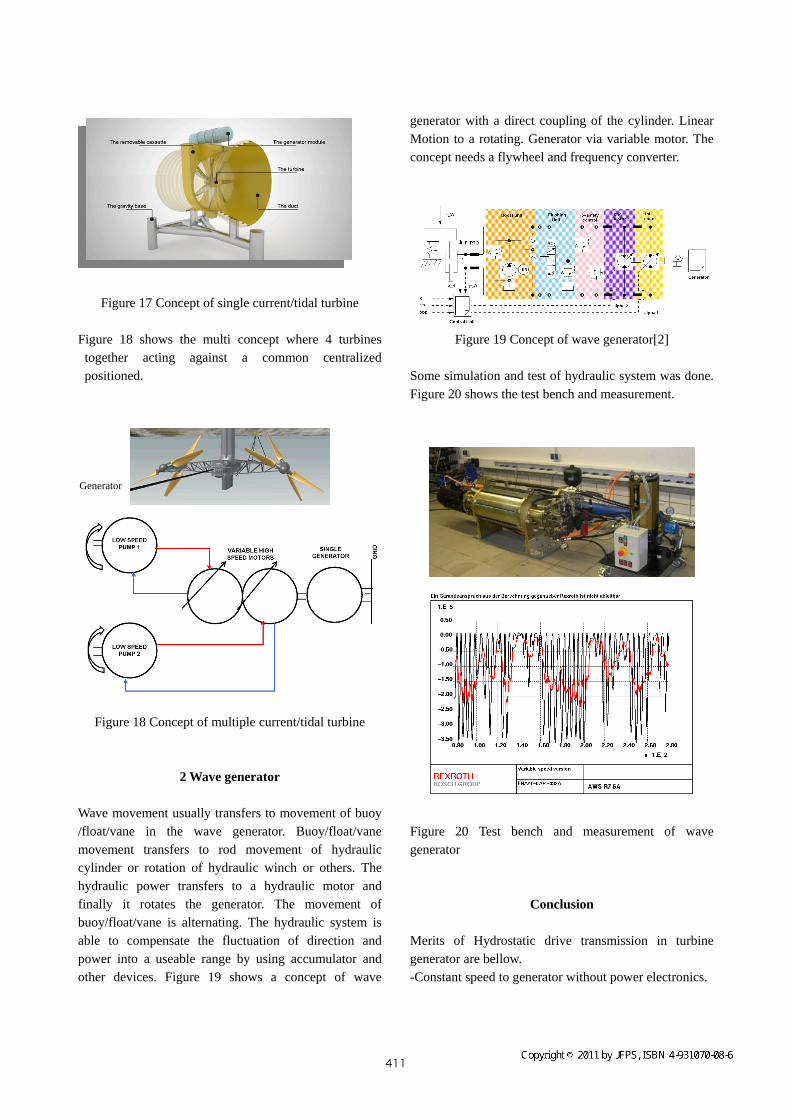
Figure 17 Concept of single current/tidal turbine
Figure 18 shows the multi concept where 4 turbines together acting against a common centralized positioned.
Figure 18 Concept of multiple current/tidal turbine
2 Wave generator
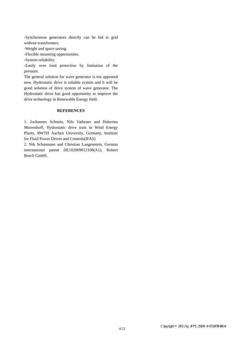
Wave movement usually transfers to movement of buoy /float/vane in the wave generator. Buoy/float/vane movement transfers to rod movement of hydraulic cylinder or rotation of hydraulic winch or others. The hydraulic power transfers to a hydraulic motor and finally it rotates the generator. The movement of buoy/float/vane is alternating. The hydraulic system is able to compensate the fluctuation of direction and power into a useable range by using accumulator and other devices. Figure 19 shows a concept of wave
generator with a direct coupling of the cylinder. Linear Motion to a rotating. Generator via variable motor. The concept needs a flywheel and frequency converter.
Figure 19 Concept of wave generator[2]
Some simulation and test of hydraulic system was done. Figure 20 shows the test bench and measurement.
Generator
Figure 20 Test bench and measurement of wave generator
Conclusion
Merits of Hydrostatic drive transmission in turbine generator are bellow. -Constant speed to generator without power electronics.
411
-Synchronous generators directly can be fed to grid without transformers. -Weight and space saving. -Flexible mounting opportunities. -System reliability. -Easily over load protection by limitation of the pressure. The general solution for wave generator is not appeared now. Hydrostatic drive is reliable system and it will be good solution of drive system of wave generator. The Hydrostatic drive has good opportunity to improve the drive technology in Renewable Energy field.
REFERENCES 1. Jochannes Schmitz, Nils Vatheuer and Hubertus Murrenhoff, Hydrostatic drive train in Wind Energy Plants, RWTH Aachen University, Germany, Institute for Fluid Power Drives and Controls(IFAS) 2. Nik Scharmann and Christian Langenstein, German international patent DE102009012108(A1), Robert Bosch GmbH.