105 SP-258—7 Hysteretic Rotation Model HRM4 for CFRP-Strengthened Joints by P.F. Silva Synopsis: A simple hysteretic model is proposed to define the cyclic response of reinforced concrete (RC) beam to column joints retrofitted with (carbon fiber-reinforced polymer (CFRP) composites. This model includes the option to consider strength degradation resulting from damage within the joint region. The model consists of two nonlinear springs connected in series and positioned at the ends of linear elastic beam elements. The hysteretic models representing these springs were empirically derived from beam to column joint specimens retrofitted with CFRP composites and are capable of describing the hysteretic characteristics of reinforced concrete members in the column as well as in the joint hinge region. The model was subsequently used to evaluate the response of two test units that were retrofitted with CFRP composites at different damage levels. Key experimental results along with the proposed models and simulation results are presented and discussed in this paper. The analytical results were able to reproduce reasonably well the experimental data. Keywords: beam-column joint; fiber-reinforced polymer composites; hysteretic models; joint damage; joint flexibility
Transcript
105
SP-258—7
Hysteretic Rotation Model HRM4 for CFRP-Strengthened Joints
by P.F. Silva
Synopsis: A simple hysteretic model is proposed to define the cyclic response of reinforced concrete (RC) beam to column joints retrofitted with (carbon fiber-reinforced polymer (CFRP) composites. This model includes the option to consider strength degradation resulting from damage within the joint region. The model consists of two nonlinear springs connected in series and positioned at the ends of linear elastic beam elements. The hysteretic models representing these springs were empirically derived from beam to column joint specimens retrofitted with CFRP composites and are capable of describing the hysteretic characteristics of reinforced concrete members in the column as well as in the joint hinge region. The model was subsequently used to evaluate the response of two test units that were retrofitted with CFRP composites at different damage levels. Key experimental results along with the proposed models and simulation results are presented and discussed in this paper. The analytical results were able to reproduce reasonably well the experimental data.
Pedro F. Silva is an Associate Professor of civil and environmental engineering at the George Washington University, DC. He is a member of the ACI Committees 440, Fiber Reinforced Polymer Reinforcement, and 341, Earthquake-Resistant Concrete Bridges. His research interests include the development of innovative performance-based procedures for the design and retrofit of structures, and use of fiber-reinforced polymers for the structural rehabilitation of structures.
INTRODUCTION
Extensive research has been conducted to model the hysteretic behavior of RC members under reversed cyclic loading. Early models included the simple two-component beam model (Clough et. al., 1965), which is capable of describing bilinear moment-curvature relationships of RC members. In this model, the bilinear moment-curvature relationships are achieved by defining two beam elements connected in parallel such that one element represents the post-yield stiffness and one other is represented by an elastic-perfectly plastic relationship. A disadvantage in implementing this model is the difficulty in obtaining the strength and stiffness degradation that RC members experience under reversed cyclic loading. Other studies by Giberson (1967, 1969) developed a hysteretic model that was able to reproduce the strength and stiffness degradation that RC members experience under reversed cyclic loading. This model is known as the one component Giberson beam model and uses nonlinear rotational springs positioned at the ends of beam elements. The local member stiffness matrix described herein was accomplished using the one component Giberson beam model.
In order to implement either of these two models in the analysis of RC members under cyclic loading, hysteresis loading and unloading rules or laws are needed to describe the cyclic behavior of RC members. Many hysteresis rules have been proposed to date by Clough (1966a, 1966b), Takeda et al. (1970), Saiidi and Sozen (1981), Saiidi (1982), Stone and Taylor (1992), Jirsa and Feghali (1999), and Ilki and Kumbasar (2000). Among these models, the Takeda’s model is one of the most widely used models to describe the hysteretic response of RC members. In this study this model was also implemented with a slight modification. In the Takeda model the unloading stiffness consists of a single branch; however, in the proposed model the unloading stiffness was further decomposed in a secondary branch to accentuate the stiffness degradation during unloading very similar to the method proposed by Fukada (1969; Otani, 1981). By combining the Takeda with the Fukada hysteresis rule the model proposed herein can reproduce reasonably well the stiffness degradation as well as the pinching that is typically observed in the hysteresis of RC members.
Another feature of the model proposed herein is the incorporation of a secondary nonlinear spring with zero length, which is positioned also at the ends of elastic members. This nonlinear spring is primarily used to model the cyclic strength degradation of beam to column joints retrofitted with CFRP composites. This joint hysteretic model was similar to the Takeda hysteretic model. By separating the nonlinear deformations in two nonlinear springs one can directly infer the damage levels achieved in the member end plastic hinge and joint regions without the need for further post processing of the data. In this form, this model can be of particular interest in assessing the seismic vulnerability of existing structures built with insufficient joint shear reinforcement and propose retrofit strategies to properly develop the required nonlinear member end rotations.
PREVIOUS WORK
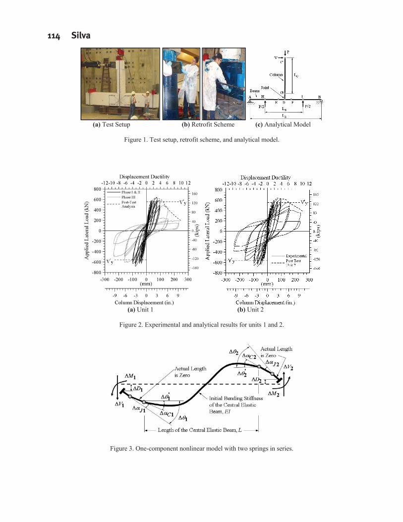
In the previous work by Silva et al. (2007) the response of beam to column joints retrofitted with CFRP composites was investigated according to the test setup presented in Figure 1a. Part of this experimental work, two test units, designated as Units 1 and 2, were retrofitted in the column plastic hinge and joint region with CFRP composites according to the retrofit scheme presented in Figure 1b. While Unit 1 was retrofitted at different damage levels, Unit 2 was strengthened in its undamaged condition according to nearly the same retrofit scheme.
In its unstrengthened condition, Unit 1 was tested up to onset of column shear failure. At this performance level, the column was strengthened using CFRP-sheets to increase its confinement and shear capacity. After retrofit, testing proceeded up to onset of joint shear failure. At this performance level, the beam and joint regions were strengthened with CFRP-sheets. Testing continued until the next failure mode was observed. Unit 1 test results indicate that the confinement and shear capacity of the column were enhanced by strengthening of the column with CFRP-sheets in the hoop direction. Although rebar fracture was observed under low cycle fatigue, the failure mode was best characterized by anchorage failure of the column longitudinal reinforcement due to joint shear failure
Seismic Strengthening of Concrete Buildings 107
beyond a displacement ductility of 4. As such, test results indicate that the repair and retrofit schemes employed in the damaged or undamaged columns were equally efficient in preventing shear failure of the column. On the other hand, while repairing the damaged beam-column joint in Unit 1 was inefficient, retrofitting the undamaged joint of Unit 2 was successful. In this paper, the proposed hysteretic rotation model (HRM) for FRP strengthened joints was used to evaluate Unit 1 up to onset of joint shear failure, and Unit 2 up to ultimate failure, which was characterized by low cycle fatigue of the column longitudinal reinforcement.
Previous research have dealt with developing tools to investigate the vulnerability of existing RC beam-column subassemblies (Priestley et al., 1995; Mazzoni and Moehle, 2001) and to develop retrofit measures to ensure appropriate ductile behavior of beam to column joints (Seible et al., 1997; Pantelides et al., 1999; Gergely et al.,2000). These and many more citations report on many assessment and retrofit measures that were used to retrofit existing RC beam-column subassemblies built with improper seismic detailing and the improvements in their seismic performance after retrofit measures were implemented in construction. However, analytical tools are insufficient that can clearly duplicate the degradation in strength that as-built and retrofitted joints experience under seismic loads.
An analytical model was previously proposed to include the contribution of joint flexibility into the lateral response of beam column joints (Mazzoni and Moehle, 2001). This model was subsequently implemented to estimate the response of the two test units shown in Figure 1a, which were tested under increasing monotonic loading with the inclusion of joint flexibility. Since prior to the 1970’s, joints were built with insufficient joint shear reinforcement; as such, mechanisms of deformation which consider rigid body rotations at the ends of members due to joint flexibility and elongation combined with slip of the longitudinal reinforcement must be incorporated in the analysis (Mazzoni and Moehle, 2001). Previously these additional modes of joint deformation were considered in the analysis of the model shown in Figure 1c by (Silva et al., 2007):
12 2
, , ,
/ 2 / 21 C b C bi i
C i B i J i
L h L hV D
K K K(1)
Where Vi and Di are the incremental column lateral load and top deflection, respectively, LC is the column height (see Figure 1b), hb is the depth of the beam and joint, KC,i is the instantaneous tangential bending stiffness for the column bending response, KB,i is the instantaneous tangential rotational stiffness of the joint contribution to the column top deflection. In this form the first two terms consider only the column and beam flexibility, and KJ,i is the rigid body rotational stiffness of the joint, which considers the rigid body rotation at the base of the column due to joint flexibility combined with bar elongation and slip. This formulation was used to analyze the structure shown in Figure 1a with results matching reasonably well the experimental results. Implementation of this model is discussed in further detail in Silva et al. (2007).
Based on this model the curve envelopes for each of the test units are shown in Figure 2, which depict a good correlation between the proposed joint model results and the experimental curves. However, this formulation did not account for the hysteretic behavior of beam column joints. The hysteretic formulation for beam column joints retrofitted with CFRP composites is presented in the next sections of this paper.
FORMULATION OF THE ELEMENT LEVEL STIFFNESS MATRIX – HRM4
In this paper the formulation of the element level stiffness matrix was developed based on the Giberson’s one component beam element (Giberson, 1967, 1969). The Giberson's model main advantage relies on the fact that any kind of hysteresis rule can be assigned to nonlinear springs, which are placed at the ends of elastic members. Due to its simplicity and potential in describing the strength and stiffness degradation, this accounts for the wide use of this model in many analytical studies (Filippou and Issa, 1988; Ilki and Kumbasar, 2000). As such, this model was also selected in this study to develop the element level stiffness matrix.
In previous hysteretic models the cyclic response of subassemblies was developed by combining the effects of plastic hinging in the columns and degradation within the joints into a single spring positioned at the ends of elastic members. In this work, the element level stiffness matrix was developed in terms of two spring elements describing
108 Silva
separately the hysteretic response of plastic hinging at the member ends and cyclic strength degradation within the joints. These two springs were considered to act in series and are shown in Figure 3.
In developing the local stiffness matrix for the one-component formulation two hinges are assumed to form at each end of elastic members. One spring considers the hysteretic response of the column plastic hinge and the other spring is connected in series and represents the hysteretic response within the joint region. Based on this four hinge model formulation and designated in this paper as HRM4, the member equilibrium equation is given by the relation:
u'oKV (2)
Where { V} and { u} are the incremental vectors representing the member end actions and corresponding displacements at the member degrees of freedom, and [Ko] is the symmetric elastic stiffness matrix of the central elastic beam element. Vector u consists of the following:
u u where
1
1
2
2
u =
D
Dand 1 1
2 2
0
0C J
C J
(3)
Where as shown in Figure 3, at each end 1 and 2, respectively, D1 and D2 are the incremental displacements, 1 and 2 are the overall incremental rotations, and C1, J1, C2 and J2 are the nonlinear or plastic hinge
and joint incremental rotations, respectively. The relation between these plastic rotations and the corresponding incremental moments, M1 and M2, are written in terms of the following flexibilities:
1 1 1 1 1 1 1
2 2 2 2 2 2 2
C J C J
C J C J
M F M FM F M F
(4)
Where FC1, FJ1, FC2 and FJ2 are the flexibility coefficients for the column hinge and joint rotation springs, respectively. In Eq. (4) the incremental moments are:
11
1 1C J
MF F
and 22
2 2C J
MF F (5)
Next, the column flexibilities coefficients are expressed in terms of the relations: 1
1 4CLF
EI, 2
2 4CLF
EI where 11
11
14 P rLL r
and 222
2
14 P rLL r
(6)
Where LP1 and LP2 are the column plastic hinge lengths at ends 1 and 2, respectively, EI and L are the initial bending stiffness and length of the central elastic beam member. Substituting these relations into Eq. (5) one obtains:
11
1 1
44
J
EIM EI LFL
and 22
2 2
44
J
EIM EI LFL
(7)
Next, the incremental moments are further simplified by the relations:
1 1 14EIM S
L 2 2 24EIM S
L (8)
Where the variables S1 and S2 are given by:
1
1 1
14
J
SEIFL
, and 2
2 2
14
J
SEIFL
(9)
Expanding on Eq. (2) one obtains the expression:
Seismic Strengthening of Concrete Buildings 109
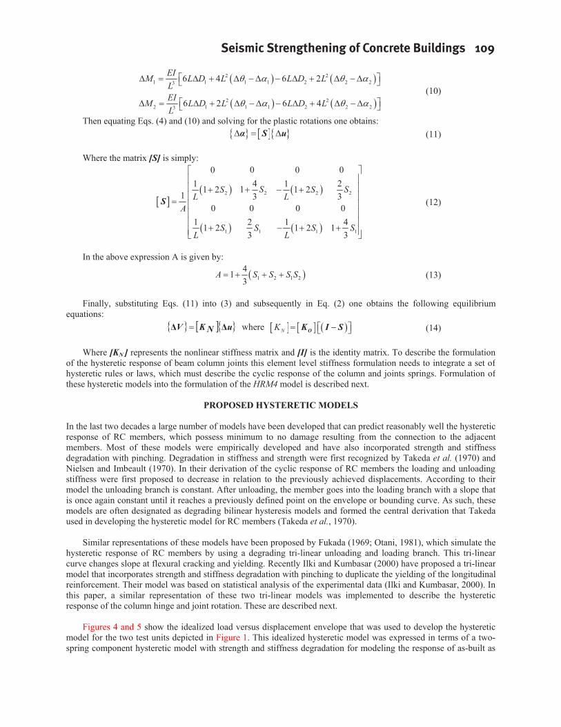
2 21 1 1 1 2 2 23 6 4 6 2EIM L D L L D L
L2 2
2 1 1 1 2 2 23 6 2 6 4EIM L D L L D LL
(10)
Then equating Eqs. (4) and (10) and solving for the plastic rotations one obtains: S u (11)
Where the matrix [S] is simply:
2 22 2
1 1 1 1
0 00 04 21 111 2 1 21 3 3
0 0 0 01 2 1 41 2 1 2 1
3 3
SS SS S
L LA
S S S SL L
(12)
In the above expression A is given by:
1 2 1 2413
A S S S S (13)
Finally, substituting Eqs. (11) into (3) and subsequently in Eq. (2) one obtains the following equilibrium equations:
uNKV where OK I SNK (14)
Where [KN ] represents the nonlinear stiffness matrix and [I] is the identity matrix. To describe the formulation of the hysteretic response of beam column joints this element level stiffness formulation needs to integrate a set of hysteretic rules or laws, which must describe the cyclic response of the column and joints springs. Formulation of these hysteretic models into the formulation of the HRM4 model is described next.
PROPOSED HYSTERETIC MODELS
In the last two decades a large number of models have been developed that can predict reasonably well the hysteretic response of RC members, which possess minimum to no damage resulting from the connection to the adjacent members. Most of these models were empirically developed and have also incorporated strength and stiffness degradation with pinching. Degradation in stiffness and strength were first recognized by Takeda et al. (1970) and Nielsen and Imbeault (1970). In their derivation of the cyclic response of RC members the loading and unloading stiffness were first proposed to decrease in relation to the previously achieved displacements. According to their model the unloading branch is constant. After unloading, the member goes into the loading branch with a slope that is once again constant until it reaches a previously defined point on the envelope or bounding curve. As such, these models are often designated as degrading bilinear hysteresis models and formed the central derivation that Takeda used in developing the hysteretic model for RC members (Takeda et al., 1970).
Similar representations of these models have been proposed by Fukada (1969; Otani, 1981), which simulate the hysteretic response of RC members by using a degrading tri-linear unloading and loading branch. This tri-linear curve changes slope at flexural cracking and yielding. Recently Ilki and Kumbasar (2000) have proposed a tri-linear model that incorporates strength and stiffness degradation with pinching to duplicate the yielding of the longitudinal reinforcement. Their model was based on statistical analysis of the experimental data (Ilki and Kumbasar, 2000). In this paper, a similar representation of these two tri-linear models was implemented to describe the hysteretic response of the column hinge and joint rotation. These are described next.
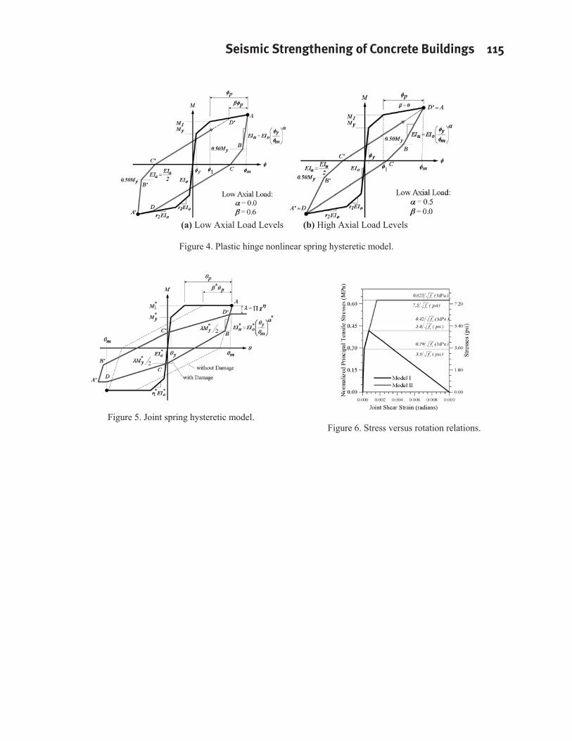
Figures 4 and 5 show the idealized load versus displacement envelope that was used to develop the hysteretic model for the two test units depicted in Figure 1. This idealized hysteretic model was expressed in terms of a two-spring component hysteretic model with strength and stiffness degradation for modeling the response of as-built as
110 Silva
well as retrofitted beam to column joints with CFRP composites. A main advantage of separating the inelastic response of RC members in two springs is the clear and ease in examining the damage levels that develop in either of the two components, which are the column plastic hinge and the joint region. The two nonlinear springs that constitute the formulation of the HRM4 model stiffness formulation are described next.
Plastic Hinge Nonlinear Spring Hysteresis Rules
Unloading and loading of the member end plastic hinge spring was accomplished according to the hysteresis rules depicted in Figure 4. In this figure the heavy dark curves represent the backbone curve and is used as the bounding curve for the hysteresis model simulation. This curve is tri-linear and was developed from on a moment curvature analysis of the RC section.
Representation of the hysteretic response of RC members within the plastic hinge region was very similar to other models established in the literature and include a constant unloading branch of magnitude given by (Takeda, 1970):
m
you EIEI (15)
During unloading when the value of the moment at the spring level drops below 50% (point B of B’ Figure 3) of the plastic hinge yielding moment the unloading stiffness reduces to 50% of the magnitude expressed in terms of Eq. (15). This change in the unloading branch has been previously supported by experimental evidence and suggested by Fukada (1969; Otani, 1981). The main difference is that in the model proposed in Figure 3 and for simplicity, the change in the unloading branch was set constant at 50%My. In the subsequent loading branch from point C to D the stiffness is given by the Takeda model (1970).
According to the Takeda hysteretic model parameters and are used to completely represent the nonlinear hysteretic response of reinforced concrete members under fully reversed cyclic loading. These parameters are as follows: describes the unloading stiffness and it is in the range of zero to 0.5, and describes the reloading stiffness and varies from zero to 0.6. It can be shown that increasing decreases the unloading stiffness, and increasing increases the reloading stiffness. Assigning specific values to and , it is possible to duplicate the response of a reinforced concrete member under different levels of axial load.
Selecting to 0.5, and to zero leads to the hysteretic response shown in Figure 4a. In this case, these values are more efficient to represent a reinforced concrete member subjected to an axial load ratio of 5 to 10 percent (Silva and Seible, 2001). On the other hand, setting and equal to zero and 0.6, respectively, leads to the hysteretic response shown in Figure 4b. This hysteretic response is typical of RC members subjected to low axial load levels and matches results reported in the literature (Priestley et al, 1995).
Extensive research exits in the literature that clearly delineates the problems associated with the cyclic loading of RC members built with insufficient transverse reinforcement, and the benefits of retrofitting these members with CFRP jackets for enhancement of the displacement ductility and shear capacity of RC members (Seible et al., 1997). It is expected that retrofitting of RC members with CFRP composites will minimize or avoid altogether any load degradation under reversed cyclic loading. As such, only stiffness degradation in terms of the Takeda hysteretic model was considered in describing the hysteretic model of plastic hinges retrofitted with composites. In the analytical model presented in this paper strength degradation was mainly considered within the joint region and is described in the next section.
Joint Nonlinear Spring Hysteresis Rules
Mazzoni and Moehle (2001) have proposed a joint moment-rotation model that combines the nonlinear flexural behavior of RC members within the plastic hinge region and the nonlinear joint moment rotation representative of rotations due to bar elongation and slip and joint deformations in a single nonlinear spring. In this paper, these modes of nonlinear deformations were considered in the analysis in terms of two individual nonlinear springs as illustrated in Figure 3. The nonlinear hysteretic relations for these two springs were based on empirical evidence and
Seismic Strengthening of Concrete Buildings 111
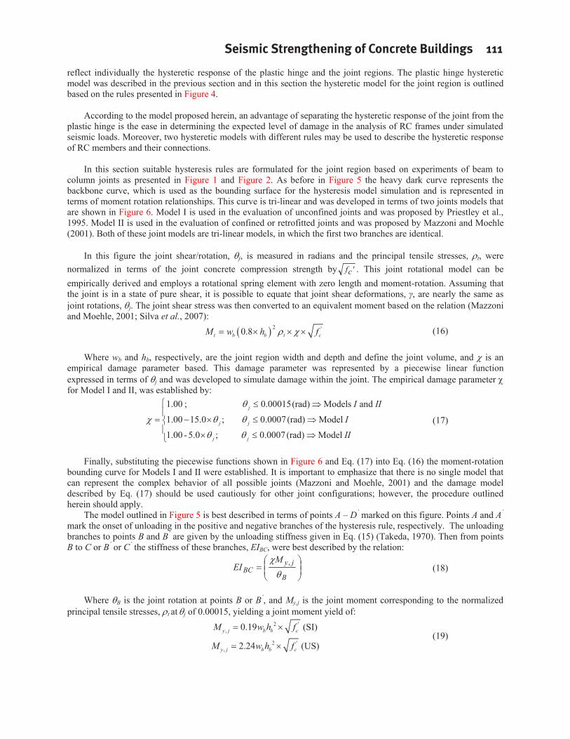
reflect individually the hysteretic response of the plastic hinge and the joint regions. The plastic hinge hysteretic model was described in the previous section and in this section the hysteretic model for the joint region is outlined based on the rules presented in Figure 4.
According to the model proposed herein, an advantage of separating the hysteretic response of the joint from the plastic hinge is the ease in determining the expected level of damage in the analysis of RC frames under simulated seismic loads. Moreover, two hysteretic models with different rules may be used to describe the hysteretic response of RC members and their connections.
In this section suitable hysteresis rules are formulated for the joint region based on experiments of beam to column joints as presented in Figure 1 and Figure 2. As before in Figure 5 the heavy dark curve represents the backbone curve, which is used as the bounding surface for the hysteresis model simulation and is represented in terms of moment rotation relationships. This curve is tri-linear and was developed in terms of two joints models that are shown in Figure 6. Model I is used in the evaluation of unconfined joints and was proposed by Priestley et al., 1995. Model II is used in the evaluation of confined or retrofitted joints and was proposed by Mazzoni and Moehle (2001). Both of these joint models are tri-linear models, in which the first two branches are identical.
In this figure the joint shear/rotation, j, is measured in radians and the principal tensile stresses, t, were normalized in terms of the joint concrete compression strength by 'cf . This joint rotational model can be empirically derived and employs a rotational spring element with zero length and moment-rotation. Assuming that the joint is in a state of pure shear, it is possible to equate that joint shear deformations, , are nearly the same as joint rotations, j. The joint shear stress was then converted to an equivalent moment based on the relation (Mazzoni and Moehle, 2001; Silva et al., 2007):
2 '0.8t b b t cM w h f (16)
Where wb and hb, respectively, are the joint region width and depth and define the joint volume, and is an empirical damage parameter based. This damage parameter was represented by a piecewise linear function expressed in terms of j and was developed to simulate damage within the joint. The empirical damage parameter for Model I and II, was established by:
1.00 ; 0.00015(rad) Models and
1.00 15.0 ; 0.0007(rad) Model
1.00 - 5.0 ; 0.0007(rad) Model
j
j j
j j
I IIIII
(17)
Finally, substituting the piecewise functions shown in Figure 6 and Eq. (17) into Eq. (16) the moment-rotation bounding curve for Models I and II were established. It is important to emphasize that there is no single model that can represent the complex behavior of all possible joints (Mazzoni and Moehle, 2001) and the damage model described by Eq. (17) should be used cautiously for other joint configurations; however, the procedure outlinedherein should apply.
The model outlined in Figure 5 is best described in terms of points A – D’ marked on this figure. Points A and A’
mark the onset of unloading in the positive and negative branches of the hysteresis rule, respectively. The unloading branches to points B and B’ are given by the unloading stiffness given in Eq. (15) (Takeda, 1970). Then from points B to C or B’ or C’ the stiffness of these branches, EIBC, were best described by the relation:
B
jyBC
MEI , (18)
Where B is the joint rotation at points B or B’, and My,j is the joint moment corresponding to the normalized principal tensile stresses, t at j of 0.00015, yielding a joint moment yield of:
2 ', 0.19y j b b cM w h f (SI)
2 ', 2.24y j b b cM w h f (US)
(19)
112 Silva
Completion of the hysteresis rule from points C to D or C’ to D’ is accomplished by decreasing the moment value from the previous cycle at points A and A’ by the damage parameter , with a complete cycle depicted in Figure 5.
EVALUATION OF PROPOSED MODEL
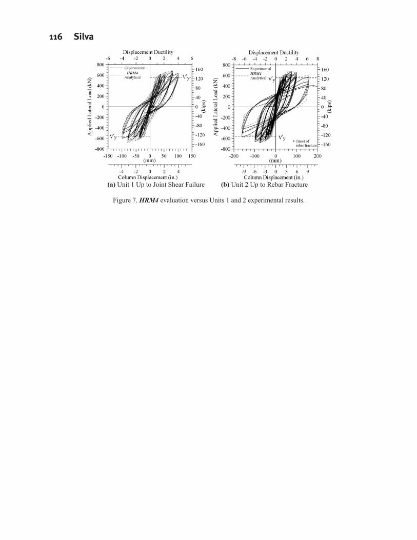
Numerical evaluation of the hysteretic model described in the previous sections is performed and presented in this section. The hysteretic model was evaluated according to the loading protocol employed during testing of the two beam column joints tests shown in Figure 1 and experimental results depicted in Figure 2. As previously stated, the proposed HRM4 model for FRP strengthened joints was used to evaluate Unit 1 up to onset of joint shear failure, and Unit 2 up to ultimate failure.
Results of these analyses are depicted in Figure 7. This figure clearly shows that model HRM4 was able to reproduce reasonably well the cyclic response of the two units. Overall the hysteretic response of Unit 1 displayed reasonable levels of energy absorption capacity with significant pinching, which is a characteristic of joint shear failure and was well reproduced by the hysteretic model as shown in Figure 7a.
In comparison to Unit 1, the overall hysteretic response of Unit 2 displayed an increasing level of energy absorption capacity and a decrease in the pinching of the hysteresis loops, which as shown in Figure 7b was well reproduced by the HRM4 model. Furthermore, although there was some level of joint flexibility and damage, the predominant failure mode for Unit 2 was mainly characterized by low cycle fatigue fracture of the column longitudinal reinforcement.
CONCLUSIONS
This paper presents the numerical implementation of a relatively simple hysteretic model, designated as HRM4herein, that was able to duplicate reasonably well the cyclic response of reinforced concrete (RC) beam to column joints retrofitted with carbon fiber reinforced polymer (CFRP) composites. The following can be concluded:
1) The empirical joint moment rotation model presented herein was successful in estimating the level of strength and stiffness degradation for each of the units.
2) The loading and unloading rules used to describe the hysteretic models were expressed in terms of two springs connected in series with stiffness and strength degradation that are likely to develop in retrofitted joints. This model reproduced reasonably well the cyclic response of the test units and their degradation in stiffness and capacity due to joint damage.
3) Research presented in this paper and elsewhere has shown that while most retrofitted RC joints may not remain elastic at high shear force transfers, they are able to safely guarantee moderate levels of system ductility capacity under the design event. Incorporation of joint inelastic rotations models, such as those presented in this paper, in design/assessment may lead to the implementation of retrofit solutions that are economically feasible.
In current seismic assessment of bridges, the hysteretic seismic response of beam to column joints and their associated joint damage has often been neglected or greatly simplified. As such, the models outlined in this paper can lead to a better understating of the efficiency of bridges related to the redistribution of inelastic actions and its implication in the retrofit design of joints possessing moderate levels of ductility capacity. As such, the hysteric model developed in this paper is a viable tool to properly investigate the seismic response of RC structures which account for the correct representation of the contribution of joint flexibility and damage to system seismic response.
REFERENCES
Clough, R.W., Benuska, K.L. and Lin, T.Y. (1966a), “FHA Study of Seismic Design Criteria for High Rise Buildings,” HUDTS-3, Aug. 1966, Federal Housing Administration, Washington D.C.
Clough, R.W. (1966b), “Effect of Stiffness Degradation on Earthquake Ductility Requirements,” Structural and Materials Research, Univ. of California, Berkeley, CA., Report No. SEMM 66-16, Oct. 1966. 67pp.
Seismic Strengthening of Concrete Buildings 113
Clough, R.W., Benuska, K.L., and Wilson, E.L. (1965), “Inelastic Earthquake Response of Tall Buildings,” Proceedings, Third World Conference on Earthquake Engineering, New Zealand National Committee on Earthquake Engineering, Vol. 2, 1965, pp. 68-69.
Filippou, F.C., and Issa, A. (1988), “Nonlinear Analysis of Reinforced Concrete Frames under Cyclic Load Reversals,” Report No. UCB/EERC–88/12, Earthquake Engineering Research Center College of Engineering, University of California, Berkeley, CA., Sept. 1988, 107pp.
Fukada, Y. (1969), “Study on the Restoring Force Characteristics of Reinforced Concrete Buildings (in Japanese),” Proceedings, Kanto Branch Symposium, Architectural Institute of Japan, No. 40, 1969, pp. 121-124.
Gergely, I.; Pantelides, C. P.; and Reaveley, L. D., 2000, “Shear Strengthening of R/C T-Joints using CFRP Composites,” Journal of Composite for Construction, ASCE, V. 4, No. 2, May, pp. 56-64.
Giberson, M.F. (1967), “The Response of Nonlinear Multi-Story Structures subjected to Earthquake Excitation,” Doctoral Dissertation, California Institute of Technology, Pasadena, CA., May 1967, 232pp.
Giberson, M.F. (1969), “Two Nonlinear Beams with Definition of Ductility,” Journal of the Structural Division, ASCE, Vol. 95, No. 2, July 1969, pp. 137-157.
Ilki, A. (2000), “The Nonlinear Behavior of Reinforced Concrete Members Subjected to Reversed Cyclic Loads, Doctoral Dissertation, Istanbul Technical University, 2000.
Ilki, A., and Kumbasar, N. (2000), “Hysteresis Model for Reinforced Concrete Members,” Fourteenth Engineering Mechanics Conference, American Society of Civil Engineers, Austin, TX., May 2000, 6pp.
Jirsa, J.O., and Feghali, H.L. (1999), “Simulation of Seismic Response of Reinforced Concrete Structures,” Proceedings of the U ur Ersoy Symposium on Structural Engineering , Middle East Technical University Press, Ankara, Turkey, July 1999, pp. 261-274.
Mazzoni, S., and Moehle, J. P. (2001), “Seismic Response of Beam-Column Joints in Double-Deck Reinforced Concrete Bridge Frames,” V. 98, No. 3, May-June 2001, pp. 259-269.
Nielsen, N.N., and F.A. Imbeault (1971), “Validity of Various Hysteretic Systems,” Proceedings, Third Japan National Conference on Earthquake Engineering, 1971, pp. 707-714.
Pantelides, C. P.; Gergely, J.; Reaveley, L. D.; and Volnyy, V. A. (1999), “Retrofit of RC Bridge Pier with CFRP Advanced Composites,” Journal of Structural Engineering, ASCE, V. 125, No. 10, Oct., pp. 1094-1099.
Priestley, M. J. N., Seible, F., and Calvi, M. (1995), Seismic Design and Retrofit of Bridges, John Wiley & Sons, Inc., New York, NY, Sep 1995, 672 pp.
Saiidi, M., “Hysteresis Models for Reinforced Concrete,” Journal of the Structural Division, ASCE, V. 108, No. 5, May 1982, pp. 1077-1087.
Saiidi, M., and Sozen, M.A. (1981), “Simple Nonlinear Seismic Analysis of RC Structures,” Journal of the Structural Division, ASCE, Vol. 107, No. ST5, May 1981.
Seible, F.; Priestley, M. J. N.; Hegemier, G.; and Innamorato, D. (1997), “Seismic Retrofitting of RC Columns with Continuous Carbon Fiber Jackets,” Journal of Composite for Construction, ASCE, V. 1, No. 2, May 1997, pp. 52-62.
Silva, P.F., Ereckson, N.J., and Chen, G. (2007), “Seismic Retrofit of Bridge Joints in the Central U.S. with CFRP Composites,” ACI Structural Journal, Vol. 104, No. 2, March 2007, pp. 207-217.
Stone, W.C., and Taylor, A.W. (1992), “A Predictive Model for Hysteretic Failure Parameters,” Proceedings of Tenth World Conference on Earthquake Engineering, Madrid, Spain, July 1992, pp. 2575-2580.
Takeda, T., Sozen, M.A. and Nielsen, N.N. (1970), “Reinforced Concrete Response to Simulated Earthquakes,” Journal of the Structural Division, ASCE, Vol. 96, No.12, Dec. 1970, pp. 2557-2573.
Otani, S. (1981), “Hysteresis Models of Reinforced Concrete for Earthquake Response Analysis,” Journal of Faculty of Engineering, University of Tokyo, Vol. 36, No. 2, 1981, pp. 407 – 441
114 Silva
(a) Test Setup (b) Retrofit Scheme (c) Analytical Model
Figure 1. Test setup, retrofit scheme, and analytical model.
(a) Unit 1 (b) Unit 2
Figure 2. Experimental and analytical results for units 1 and 2.
Figure 3. One-component nonlinear model with two springs in series.
Seismic Strengthening of Concrete Buildings 115
(a) Low Axial Load Levels (b) High Axial Load Levels
Figure 4. Plastic hinge nonlinear spring hysteretic model.
Figure 5. Joint spring hysteretic model. Figure 6. Stress versus rotation relations.
116 Silva
(a) Unit 1 Up to Joint Shear Failure (b) Unit 2 Up to Rebar Fracture
Figure 7. HRM4 evaluation versus Units 1 and 2 experimental results.