4 I-c jfZLECT DMTUftONSTATEMEW) A) - Approved for public release; McLEAN RESEARCH CENTER, INC. 1483 Chain Bridge Road, Suite 205 McLean, Virginia 22101 Reproduced From Best Available Copy 6 21
Transcript
4
I-c
jfZLECT
DMTUftONSTATEMEW) A)
- Approved for public release;
McLEAN RESEARCH CENTER, INC.1483 Chain Bridge Road, Suite 205McLean, Virginia 22101
Reproduced FromBest Available Copy 6 21
Final Technical Report
MRC -3 86MORTAR BALLISTICS COMPUTER, M23
1 February 1986
Frep~red by
Filmore Richter
Approved by DTICGeorge Schecter E CT
FEBi 18198for SFLEC
U.S. ARMY BELVOIR R&D CENTER ~.-~'Fort Belvoir, VA
and
U.S. ARMY ARMAMENT R&D CENTER
Dover, NJ
Contract No.: DAAK7O-84-D-0052, TASK 0011
M cL E AN R ES'EA R CH CE NT ER, I NC.1483 Chain Bridge Road, Suite 205, McLean, VA 22101 (703) 734-1410
DIS~pJ~wSTLATEME~JAP0p0od fOl Public reioaa.,Distribution Ualimited
UNCLASSIFIED.SECURITV CLAS114FICATIOlw Of Toos PAOEL (Wo D". frtod
REP'ORT &iOCMENTATION4 PAGE REA NCTPLUJ4GOS
. *a ww a. OVT ACCESSION NO. 3. Recipfe"W TI CATALOG "UM69R
4 TILE E i~eI. S.TYPE Of RapORT 6 PERICO COVERED
Final TechnicalMortar Ballistics Computer, M23 Jul-Dec 1985
a. PnrFORmuIG ORG. REPORT 06uweCR
MRC-3867. AUt "qOR(s) S. CONTRACT ON GRANT NfUmOCA(s,
COMPUTER, BALLISTICS, MORTAR, TYPE CLASSIFICATION,MAT2ERIEL RELEASE
20 AGSTRACT (Conrtv.. an vseo aig It n*Ro *@eA a" WiEeft by block MWsb4) -.
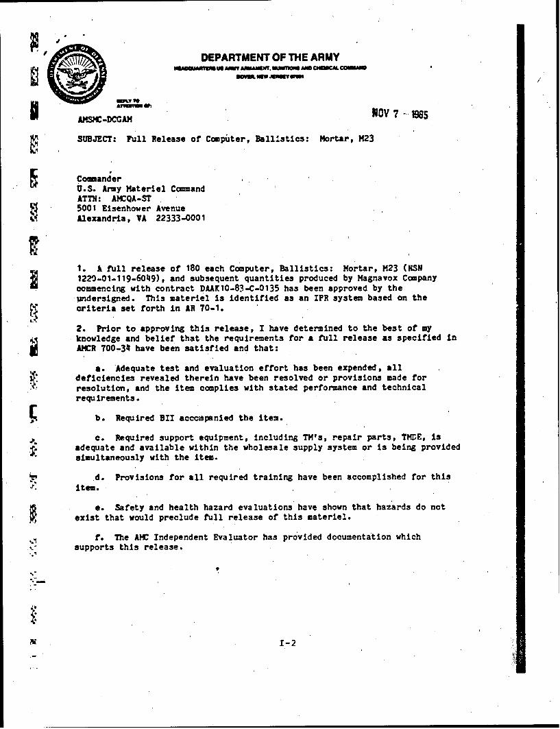
The Mortar Ballistics Computer, M23, was found to besuitable for type reclassification from Limited Procurement toStandard and full release approval was granted for full productionand. deployment. Program Management Documentation is appended, in-cluding the Computer Resources Management Plan, Materiel Release,Production Validation IPR package,.
DD 1473 too r~f OF' NOIV 6055 OGSOLETE NLSSFE
SECURITY CLASSIFICATION OF TNIS PAGE (11%ea Dols Xmt s 0
t4 -97
SET N R
A A .c *
-W l.j -
~~7Ij c.
.44' : $
-A -
'JE 2-81,~§%N;-~c- ~ SW :~ Y
4t~
1 Feb 86
STUDY GISTTROSCOM
MORTAR BALLISTICS COMPUTER, M23
The Principal Findings
1. The Mortar Ballistics Computer, M23, was found to besuitable for Type Reclassification from Limited Procurement toStandard, and for full release for production and deployment tothe field.
V 2. All required Program Management Documents were preparedor put in order, all necessary reviews were conductedsuccessfully. and full release approval was obtained.
Main Assu tions
* It was assumed that current decisions would be consistentwith past positions taken by TRADOC and AMC, and that themodifications required were well within the state-of-the-art,very low risk, and low cost.
Principal Limitations
The User community is eager to have this item issued to thefield, and the only practical limitations have to do with theUrgent target date for full release.
Scope of the Study
It was required that all elements of the system acquisitionplan, management documentation, and the system itself be ready tosupport the Type Reclassification and full materiel releasedecisions. Special emphasis was required in the' preparation ofthe Computer Resources Management Plan, Materiel Release documentpackage, Production Validation IPR package, and the EngineeringChanges identified in previous reviews.
Objectives
To achieve a successful Type Reclassification from LimitedProcurement to Standard, and to obtain approval for full releasefor production and deployment.
s~j 1
Basic Approach
The approach was straightfoward: to verify readiness of thesystem for full release in all-pertinent respects and to complywith all applicable documentation requirements.
Reason for Performing the Study
To enable full produztion to meet full deployment needs.
Sponsor
U.S. Army Belvoir R&D Center and U.S. Army Armament R&DCenter.
Performing Activity and Principal Investigator
McLean Research Center, Inc. (MRC)Principal Investigator: Filmore Richter & George Schecter
Comments and Questions
McLean ,Research Center, Inc.1483 Chain Bridge Road, Suite 205McLean, VA 22101l
Attn: Mr. George Schecter, (703) 734-1410
Actions Taken as a Result of Findings-
The Mortar Ballistics Computer, M23, was Type Reclassifiedfrom Limited Procurement to Standard, and full release wasauthorized for production and deployment.
DTIC/DLSI-Accession Number of Final Report
To be assigned.
2
IaJ
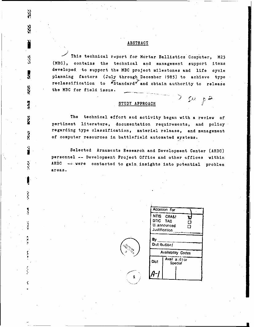
ABSTRACT
This technical report for Mortar Ballistics Computer, M23
(MBC), contains the technical and management support itemsdeveloped to support the MBC project milestones and life cycle
planning factors (July through December 1985) to achieve typereclassification to StandardI and obtain authority to release
the MBC for field issue.
STUDY APPROACH
The technical effort and activity began with a review of
pertinent literature, documentation requirements, and policyregarding type classification, materiel release, and management
of computer resources in battlefield automated systems.
Selected Armaments Research and Development Center (ARDC)
personnel -- Development Project Office and other offices within* ARDC -- were contacted to gain, insights into potential problem
3. DRDAR-QA Form 337, Evaluatin of Acceptance Inspection
Equipment Designs, 7 Dec 84, for the M23 Mortar Ballistic
Computer.,
4. First Article Test Report for Mortar Balli~tics
Computer (MBC), M23, Dec 84, prepared under contract DAAK10-83-C-
0135 fcr U.S. Army Armament Research and Development Command;
CDRL Item A034.
5. MIL-C-70489, Prime Item Product Fabricatlin for
Computer Set, Ballistics: Mortar M23, 25 Jan 85.
6. Final Report, First Article/Initial Production Test
(FA/IPT) of Computer, Ballistics: Mortar, M23, WSMR, Jan 85.
7. Letter, Magnavox Electronic System Company, 25 Jan 85,
subject: DAAK10-83-C-0135 MBC Humidity Test.
8. Letter, WSMR, STEWS-TE-LG, 31 Jul 85, subject:
Software Verification Test for the Computer, Ballistics: Mortar
(MBC), M23.
The review indicates that the previously identified
problems at the DEVA-IPR have been corrected. During First
Article/Initial Production Test, four new software deficiencies
were uncovered but of such a nature that they could be corrected
prior to full-scale production with minimal risk. The noted
deficiencies were as follows:
9
1. The MBC does not permit individual piece adjustments
after registration.
2. The test for charges greater than 32 for the 107mm
carrier-mounted mortars elevated to 1065 mils is reversed.
3. The MBC will not accurately compute 107mm mortar high
angle jolutions.
4. The MBC kayboard will lock up and preclude any
subsequent actions.
A Pre-IPR was conducted by letter to determine the AMC
position. The substance of the letter was tht the MBC: (1) meets
the requirements delineated in the Letter Requirement (LR)
against which it was evaluated, (2) is acceptable for calculating
Infantry Mortar Systems firing data, (3) is acceptable for
introduction into the Army inventory, (4) should be reclassified
as Standard, and (5) software changes will be incorporated into
the system prior to full-scale production. The above proposed
AMC position was reviewed and concurred in by the voting members
representing AMCCOM, ARDC, and TECOM.
Subsequent to the Pre-IPR, a Production Validation IPR
package was prepared and distributed. The PROD-VAL-IPR Package
covered all aspects of the program from the DEVA-IPR through
First Article/Initial Production Testing and included the
documentation attesting to the acceptability, producibility,
safety, and logistic supportability of the MBC.
In the interim between the Pre-IPR and the schaduled PROD-
VAL-IPR, the software changes to correct the deficiencies
uncovered during FAT/IPT were incorporated into the MBC and
10
/ successfully retested by TECOM. Since there were no unresolved
/ problems at this time, it was recommended that the IPR voting
members consider the possibility of conducting the PROD-VAL-IPR
by mail in lieu of attending a formal meeting at ARDC. This
recommendation was acceptable and a correspondence IPR was
conducted by the chairperson. As a result of that IPR, both the
U.S.Army Training and Doctrine Command (TRADOC) and the U.S. Army
Logistics Evaluation Agency (LEA) concurred in the type
reclassification "Standard." Headquarters, Army Materiel Command
(AMC) concurred in the Type Classification Standard without
exception. A Memorandum for Record and the Type Classification ,
Recommendation were prepared and forwarded to Commanding General,
AMCCOM, for signature/approval.
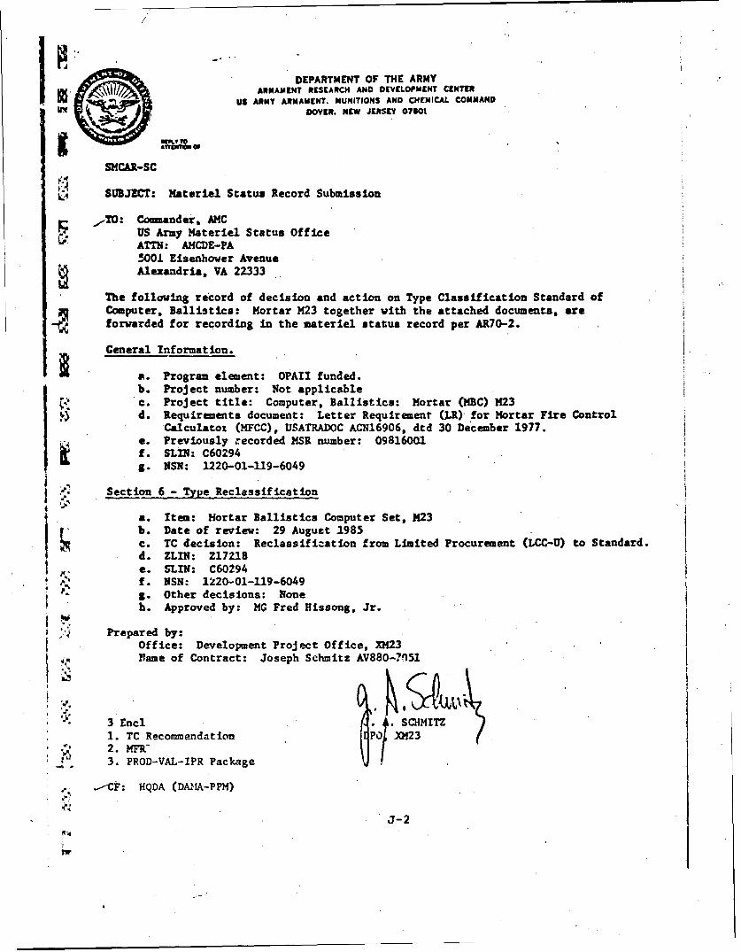
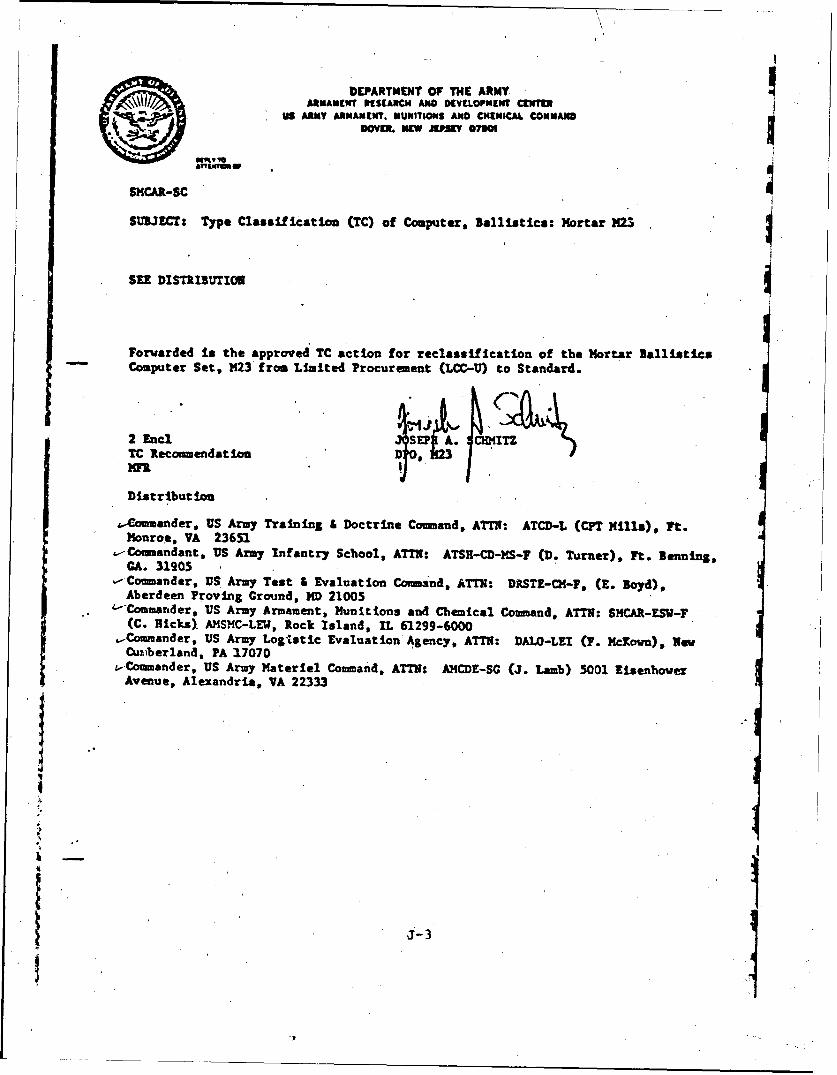
Subsequent to the approval of the reclassification action,
the record of decision and action on the type classification
(Standard) of the MBC together with documentation were submitted
to the U.S. Army Materiel Status Office for recording and
distribution to Headquarters, Department of the Army (see
Annex I).
2.4 TASK 4. ENGINEERING CHANGES
During this period, several engineering changes proposed
by the current production contractor were reviewed and evaluated.
The conclusione reached after evaluation, and the suggested
actions to be taken in each instance, i:re submitted to the
Development Project Officer (DPO) for his consideration in the
problem solution.
These changes were primarily in the areas of micro-chips
and other semi-conductor devices, and are classified into two
categories:
i .
1'. Potential (near-future) non-availability of some
components specified in the teclinical data package.
2. Modifications/changes in component specifications
resulting from changes in suppliers' manufacturing processes.
A major claim against the Government; submitted by a
contractor, was reviewed and evaluated. The findings and
recommendations were presented to the DPO for his consideration
during ensuing discussions with the Contracting Officer and the
legal office.
Currently, the Engineering Change Proposals are yet to be
negotiated with the initial and follow-on production contractors
and the above mentioned claim is in litigation. Therefore, any
disclosures regarding these pending actions is considered
prourement sensitive, premature, and beyond the scope of this
task.
With the impending deprojectizing of the Development
Project Office, the technical responsibility during the
production and deployment phase of Lhe MBC life cycle is being
assigned to Program Manager, Mortars. Consequently, a list of
pertinent documents was prepared for transmittal to the Program
Manager's Office. This effort also entailed an update of the
five-year production schedule (through FY90) and a revision to
the in-house funding synopsis for FY85 and FY86 allocations.
12
ANNEX A
REFERENCES
ANNEX A
REFERENCES
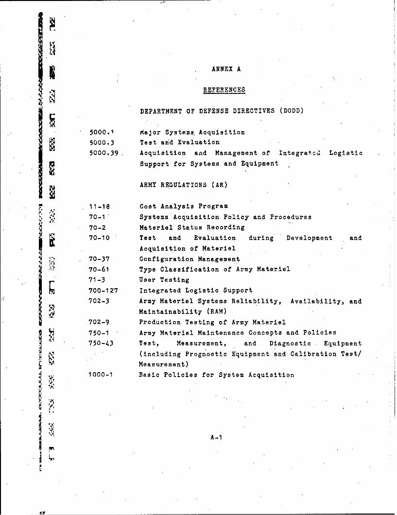
DEPARTMENT OF DEFENSE DIRECTIVES (DODD)
5000.1 Major Systems, Acquisition
5000.3 Test and Evaluation
5000.39, Acquisition aad Management of Integratc.d Logistic
Support for Systems and Equipment
ARMY REGULATIONS (AR)
11-18 Cost Analysis Program
4 70-1' Systems Acquisition Policy and Procedures
70-2 Materiel Status Recording
70-10 Test and Evaluation during Development and
Acquisition of Materiel
70-37 Configuration Management
70-61 Type Classification of Army Materiel
71-3 User Testing
700-127 Integrated Logistic Support
702-3 Army Materiel Systems Reliability, Availability, and
Maintainability (RAM)
702-9 Production Testing of Army Materiel
q 750-1 Army Materiel Maintenance Concepts and Policies
750-43 Test, Measurement, and Diagnostic Equipment
(including Prognostic Equipment and Calibration Test/
Measurement)
1000-1 Basic Policies for System Acquisition
VA-i
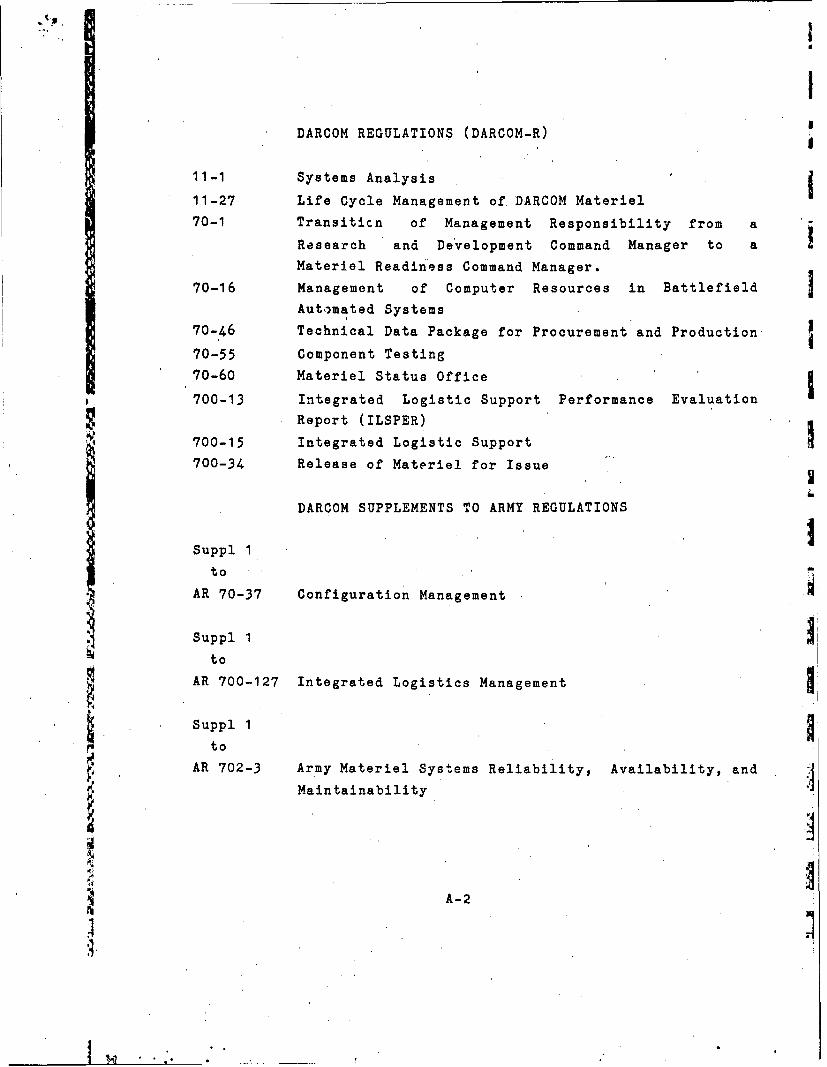
DARCOM REGULATIONS (DARCOM-R)
11-1 Systems Analysis
11-27 Life Cycle Management of DARCOM Materiel
70-1 Transiticn of Management Responsibility from a
Research and Development Command Manager to a
Materiel Readiness Command Manager.
70-16 Management of Computer Resources in Battlefield
Automated Systems
70-46 Technical Data Package for Procurement and Production
70-55 Component Testing
70-60 Materiel Status Office
700-13 Integrated Logistic Support Performance Evaluation
Report (ILSPER)
700-15 Integrated Logistic Support
700-34 Release of Materiel for Issue
DARCOM SUPPLEMENTS TO ARMY REGULATIONS
Suppl 1
to'
AR 70-37 Configuration Management
Suppl 1
to
AR 700-127 Integrated Logistics Management
Suppl I
to
AR 702-3 Army Materiel Systems Reliability, Availability, and
Maintainability
"4 A-2
C MILITARY STANDARDS (MIL STD)
480 Configuration Management
490 Specification Practices
882 System Safety Program for System, and Associated
Subsystems and Equipment, Requirement for
1388 Logistic Support Analysis
S83490 Specifications, Types and Forms
A
"" A-3
ANNEX B
LIST OF ACRONYMS
ANNEX B
LIST OF ACRONYMS
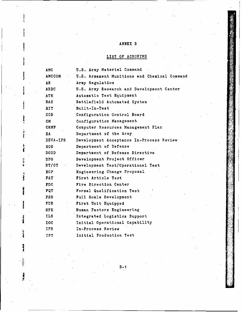
AMC U.S. Army Materiel Command
AMCCOM U.S. Armament Munitions and Chemical Command
AR Army Regulation
ARDC U.S. Army Research and Development Center
ATE Automatic Test Equipment
BAS Battlefield Automated System
BIT Built-In-Test
CCB Configuration Control Board
CM Configuration Management
CRMP Computer Resources Management Plan
DA Department of the Army
DEVA-IPR Development Acceptance In-Process Review
DOD Department of Defense
DODD Department of Defense Directive
DPO Development Project Officer
DT/OT Development Test/Operational Test
ECP Engineering Change Proposal
FAT First Article Test
FDC Fire Direction Center
FQT Formal Qualification Test
FSD Full Scale Development
FUE First Unit Equipped
HFE Human Factors Engineering
ILS Integrated Logistics Support
IOC Initial Operational Capability
IPR In-Process Review
IPT Initial Production Test
B-i
I
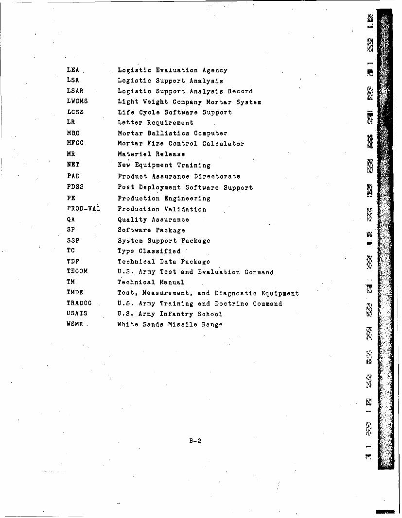
LEA Logistic Evaiuation Agency
LSA Logistic Support Analysis
LSAR Logistic Support Analysis Record
LWCMS Light Weight Company Mortar System
LCSS Life Cycle Software Support
LR Letter Requirement
MBC Mortar Ballistics Computer
MFCC Mortar Fire Control Calculator
MR Materiel Release
NET New Equipment Training
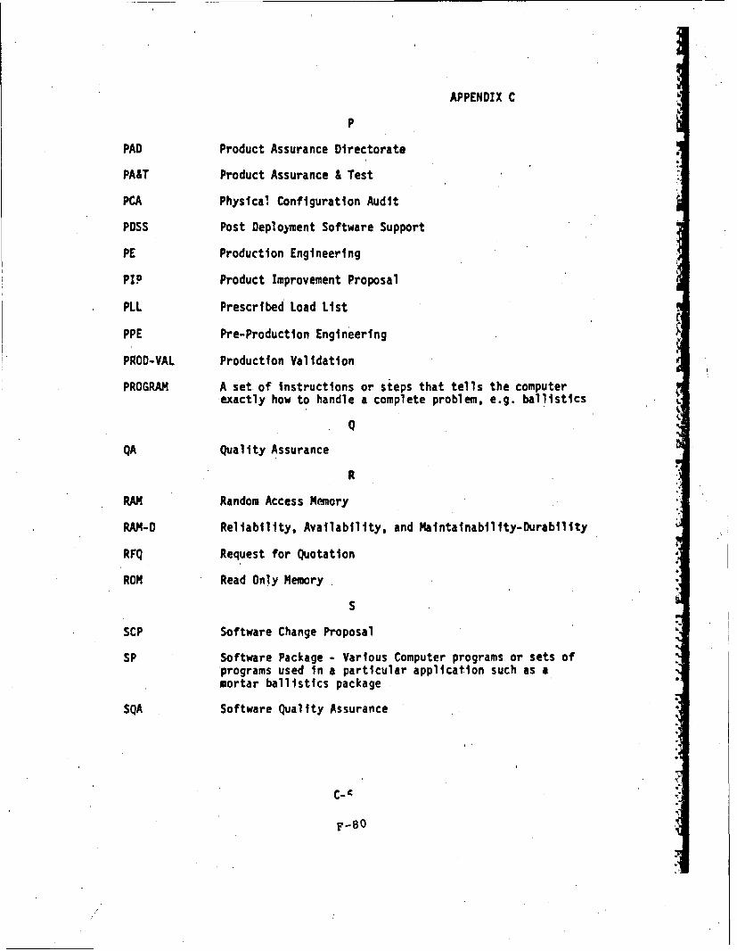
PAD Product Assurance Directorate
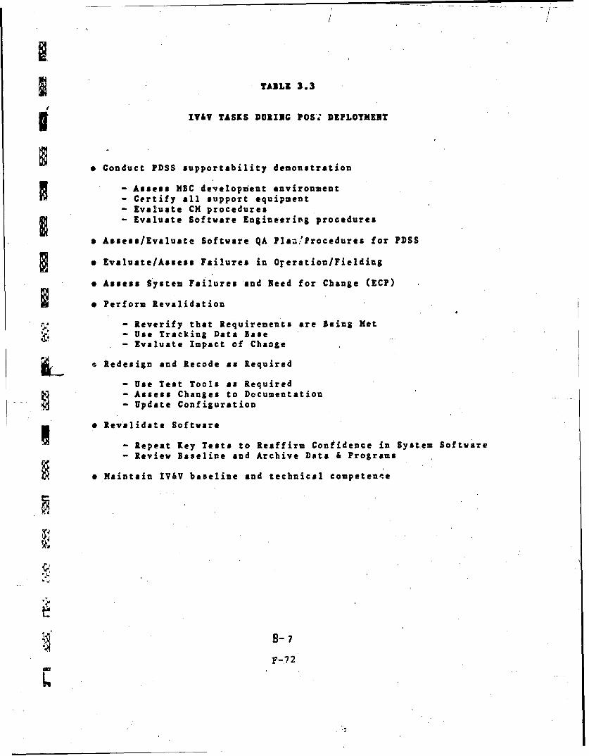
PDSS Post Deployment Software Support
PE Production Engineering
PROD-VAL Production Validation
QA Quality Assurance Vv
SP Software Package
SSP System Support Package
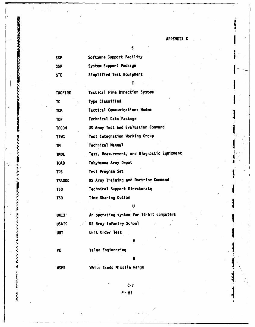
TC Type Classified
TDP Technical Data Package
TECOM U.S. Army Test and Evaluation Command
TM Technical Manual
TMDE Test, Measurement, and Diagnostic Equipment
TRADOC U.S. Army Training and Doctrine Command
USAIS U.S. Army Infantry School
WSMR White Sands Missile Range
B-2
ANNEX C
LETTER REQUIREMENT (LR)
FOR
MORTAR FIRE CONTROL CALCULATOR
USATRADOC ACN 16906
C-i
DEPARTMENT OF THE ARMY
I4I.AD0UAhI|Ik% UNIILO STATES ARMY TRAININC. ANO 1Jfl1TRINE CJMMANO
IFORT MONNOC VIRGINIA 2305
ATCD-M- I 30 December 1977
SUBJECT: Letter Requirement (I.R) for Mortar Fire Control Calculator(MFCC), USATRADOC ACN 16906
SEE DISTRIBUTION
I. Reference AR 71-9.
2.. Subject LR (inclosure 1) was approved on 13 December 1977. The.:following ipfonnation is applicable to this dociment:
a. System designation*:- Nonmajor.-r.
b. Materiel Developer: DARCOM.
c. Combat Developer: USATRADOC.
d. User Representative: USATRADOC.
e. Trainer: USATRADOC.
f. Logist'ician: USALEA.- 4.
g. .CARDS Reference Number:-- 112b.-;).
h. Operatioral Test Responsibility: USATRADOC.
i. USATRADOC Proponent Activity: USA Infantry Center.
3. Completion of action on MFCC BOIP, number 78-0018-I (USATRADOC ACN36674), is expected NLT 15 March 1978.
CF: Ch, Dev ErgMRR - E BrezonProd Eng PROJECTSys EngJ.rtej.L 3 cysD Roeck -or--g-F-2
P Run-rel
C-2
dElm
/ 14.AOU~hI H.DEPARTMENT OF THE ARFlY! Nf II. ADOUA141 s4%UNIlIO %TATES ARMY TRAINING ANO (N4TAINC E.UMMANO .
FORT MONNOC. VIRGINIA 2-IGSI
ATCD-M- I 30 December 1977 iL
* *SUBJECT: Letter Requirement (LR) for Mortar Fire Control Calculator(MFCC), USATRADOC ACN 16906
* SEE DISTRIBUTION
* 1. Reference AR 71-9.
* 2.. Subject IR (inclosure 1) was approved on 1 3 December 1977. The.following' information' is appli.cable to this docbiment:;. : .
a. :-Systei design~ition:- Ncrimajoe.-r. 1W
b. Materiel Developer:, DARCOM.
C. Combat Developer: USATRADOC. -
d. User Representative: USATRADOC.
*e. Trainer: USATRADOC.
f . 'Logistician: USALEA;.a
g. .CARDS Reference Number: -112b.Th,.
h. Opet tional Test Responsibility: USATRADoc.
1.USATRADOC Proponent Activity: USA Infantry Center. 4x
3. Completion of action on MFCC BOIP, number 78-0018-1 (USATRADOC ACN36674), is expected NLT 15 March 1978.
CF': Ch, Dev EngMRR - E BrezonProd Eng POJECTSys Eng
P Rurmel
c- 3
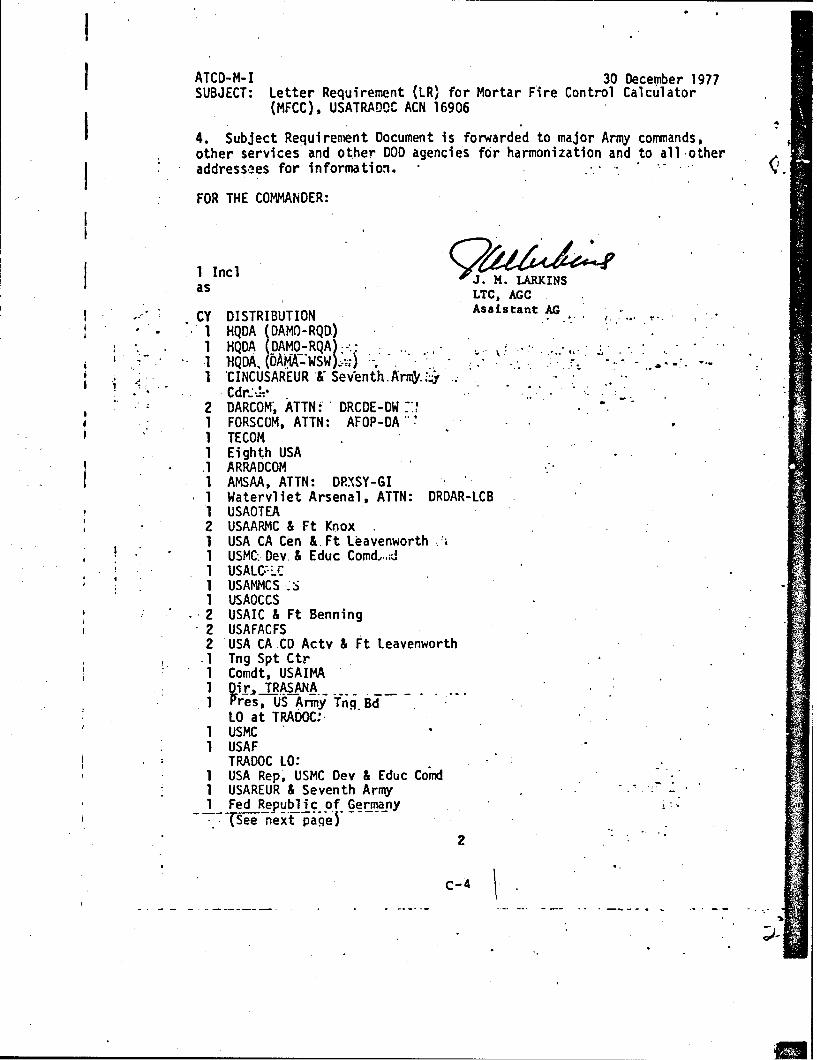
ATCD-M- I 30 December 1977SUBJECT: Letter Requirement (LR) for Mortar Fire Control Calculator
(MFCC), USATRADOC ACN 16906
4. Subject Requirement Document is forwarded to major Army conmmands,other services and other DOD agencies for harmonization and to all -otheraddressaes for information.
FOR THE COMMANDER:
1 Inc]9as LTC, AGC
CY DISTRIBUTION AssatA1 HQDA DAMO-RQD)IHQDA DAMO-RQA*.
*1 USAOTEA2 USAARMC & Ft Knox1 USA CA Cen &. Ft Le.avenworth .*iI USMC:. Dev. & Educ Comd.-d1 USALC--LC1 USAMMOS _SI USAOCCS2 USAIC & Ft Benning2 USAFACFS2 'USA CA CD Actv & Ft Leavenworth
.1 Tng Spt Ctr1 Comdt, USAIMA1 Dir. TRASANA
10 at TRADOC:.1 USMC1 USAF
TRADOC 10:1 USA Rep, USMC Dev & Educ ComdI 1 USAREUR & Seventh Army1 Fed Republic of Germany
(..See n extf -p age)2
C-4
ATCD-M-I 30 December 1977SUBJECT: Letter Requirement (IR) for Mortar Fire Control Calculator
1. TITLE OF ITEM: Mortar Fire Control Calculator (MFCC)
2. STATEMENT OF NEED:
a. The battlefield of the future will be fast moving and highlyfluid. Speed and accuracy will be essential in locating and attackingtargets and-will be major contributing factors to success in battle.
b. Infantry Mortar Systems firing data is presently calculatedthruugh the use of mortar graphical fire control equipment, firingtables and charts. Operation of this equipment is time consumingand the procedures involved make it highly subject to human error. The
, accuracy of the firing data obtained is directly related to the skilland experience of the Fire Direction Center (FDC) computer and thesharpness of his pencil. A need exists for a data calculator to replaceexisting mortar graphical firecontrol equipment as a primary method fordetermining mortar firing data in a timely manner under-prevailing condi-tions of weather, climate and enemy actions. The calculator will be usedin mortar fire direction centers.
c. CARDS Reference Number:
S3.' JUSTIFICATION:
a. The Infantry rifle company, Infantry battalion and Armor unitsare extremely dependent on the fire support provided by organic mortars.Automation of the mortar fire direction center will enable mortar elements
-to respond uiore quicklyand accurately to the needs of the maneuverelements. It is always desirable and often necessary to engage targetsimmediately without expending a large number of rounds adjusting ontothe target area. The data calculator will be capable of providing firing
* data for organic mortar units and will be utilized in all operationswhere mortars are employed.
b. The data calculator will provide the following advantages overexisting methods of obtaining data for mortar firing:
(1) Necessary firing data will be provided more quickly as computa-V tions are performed electronically. There will be no need for manual cal-
culations, graphical .work or the use of firing tables and chdrts exceptas a backup means. "
C-6
w
•(2) Data provided by the calculator will be more accurate; the chance '.
for human error will be minimized. The operator needs only be taught howto insert the proper inputs and read the outputs.
c. By automating the FDC, more speed, accuracy, and responsiveness tofire requests will be achieved. The calculator will greatly assist in.getting rounds fired rapidly onto the target and in permitting immediateengagement of targets without expending large amounts of ammunition in fireadjustment. Greater accuracy, speed of operatinn, responsiveness andsimplicity are principal elements on which justification is based.
4. BASIS OF ISSUE: The basis of issue will be two (2) Mortar Fire ControlCalculators per mortar Fire Direction Center. BOIP I action has beeninitiated by the USAIS. (USMC BOI will be two (2) per mortar platoon andtwo (2) per rifle company mortar section).
5. PRINCIPAL CHARACTERISTICS: The basic objecti've of this program is toproduce a preliminary design of a small, rugged, easy to operate and
• inexpensive computer that will eliminate the use of existing graphical fire*control. e4uipment; . The.MFCC. shall b a.:solid statel-electronic .omputing'...jdeviceiwith Waterproof m~mbrahe switch. k .yboardand panel .switches,'.circuit-. -tb6ards,-display'elem nts .and p6wersupply;'-,-The MFCC-shall. be 'capable ofbeingpowered by interchangeable primary (non-rechargeable) or secondary(rechargeable) batteries. The operator will operate the calculator through Yswitch controls, a keyboard and a digital display. The MFCC must:
a. .Be capable of calculating all fire control information required to ,
lay and fire 81mm and 4.2 inch mortar ammunition and the Lightweight CompanyMortar System (LWCMS) (60mm) that was Type Classified Standard in Jul 77.
,! b. Accept both grid coordinates.and polar plot information and produce.accurate. -mortar. firing'dta. '. :.
c. :Have.the:'capab iity.o'f qiickly*. ktoring'b.l4listic data-or utilizing-.*..-a converslon'factor for-all known cartridge/fuze combinations for.the LWCMS.-
* (60mm), 81mm and 4.2 inch mortars and the capability of changing storedballistic data whenever new firing tables are published.
d. Be capable of operating in environmental extremes, categories 1-6*as prescribed in AR 70-38.
e. Be capable of storing initialization data (referred deflection,mounting azimuth and mortar altitude) and generating fire control datafor a minimum of six mortar firing positions.in sequence.
f. Be capable of accepting the following inputs:
(1) Mortar to target azimuth (Mils).
2
C-7
•(2) Observer to target azimuth (Mils).
(3)' Propellant charge.
(4) Mortar to target range (Meters).
(5) Observer to target range (Meters).
(6) Mortar, target and observer altitudes (Meters).
(7) Meterological (MET) message in standard terms used in FM23-91(paragraph 13-22).
(8) Observer correction for deviation, range and height of burst.
(9) Range and deflection corrections after registration within transferlimits as defined in Figure 12-15, FM 23-91.
(10) Mortar, target, and observer locations in grid coordinates.
, "(11) :Mortar:referred deflection. -*.
(12). Mortar mounting azimuth.
(13) Propellant temperature.
i (14) Magnetic to grid azimuth conversion factor.'
(15) Deflection cort-ctions after registration.
(16) Location of No-Fire-Areas expressed in grid coordinates with asmany.a_ eight points each.2r;..
(17)-"Idanual ehtry of 16srdesignator'datAt(rahge, vertical ahgle-and---* , azimuth) for both target designation and correction.. .
*g. Be capable of providing the following outputs:
(1) Mortar to target range (Meters).
(2) Mortar to target azimuth and deflection (Mils).
(3) Mortar tube elevation (4ils), corrected tc include altitudedifference between position and target.
(4) Propellant charge (Increments).
(5) Time of flight (Seconds to nearest 1/10).
3
C--8
•(6) Maximum ordinate (Meters).(7) Fuze setting for illumination, smoke and HE airburst ammunition
(Seconds to nearest 1/10).
(8) Replot target coordinates.
(9) Replot target altitude (Meters).
(10) Firing azimuth (Mils).
(11) Firing deflection.
(12) Range and impact coordinates for illumination round cannister.
(13)_ Violation of No-Fire-Areas.
h. Firing data computation time shall be less than five seconds.
i.i.Be"designed for simplicityof.operatiofi so:.that.it-may.be utilized....by-gny-pembeofthemorta crew with- minimimof traininj.-:"
J. : Have a memory capability.forstoring nine forward observer loca-:tions. ,
k. Permit the operator to verify entered data"and correct such dataduring a fire mission. A
I1. Be hand 'portable and weigh no more-than six pounds to include
internal power source.
m.-- Have a self-contained throwaway and/de.rechaigeable'power source-with-a life"of lOO0-dne-minte'corputatidds under a daily'ambiefit .tempera--..tute,range of:700F -(+200).),.FoFTtestpurposes,..:.each typical-domputation.;'(fire mission) inlu~es shift from registration point, the initial-fire .command and one observer correction.
n. Have a low voltage indicator.
o. Have a power source that can be carried in the operator's pocketin low temperatures and supply power to the unit through an interconnect-ing cable. Stored data should be retained for five minutes to allow forbattery replacements and changes to pocket carry mode.
p. Provide means to use both vehicular and common generator power.Memory content will not be lost' in the changeover, from internal toexternal power or vice versa. Provisions shall be incorporated to pro-tect the calculator against excessive voltage and reverse polarity whenoperating on external power source.
4I"" C-9
j
q. Be capable of storing data for eight (8) registration points,up to Lhree (3) final protective fires and at least 50 reference pointsor othLr targets -(total of 61 locations) to include 6-10 No-Fire Areas.
* (FM 23-91, Sec I, Ch 16).
r. Compute firing data that is accuraie within 10 meters in bothrange and deflection for all ranges out to the maximum range of themorta:.
s. Have electronic components that are capable of reliable opera-tion in the electromagnetic environment normal to combat operations, toinclude. enemy electronic countermeasures (ECM). Calculator must not bedamaged or degraded by electromagnetic pulse (EMP).
t. Have a display that is legible under all expected ambient lightconditions. The readout display should not give the appearance of being
*illuminated when it is not or vice versa.
.u. :Be capable:of accepti.ng and c6mput.ing'datA for.standard.training:.-..rounds for'all types, of m6rtar." ....
v. Must not require nuclear hardening due to suffidient density, on
the battlefield..
w. Must be capable of interfacing with the DMDand/or future digital
type devices over wire and radio circuits.
x. Have built in self-test capability.
I y. Be capable of storing ballistic data, or utilizing a conversionfactor; for"all known cartridge/fuze combinations and be capable of .changing*programmed data by plug in elements-when-new firing tables' are published.!.
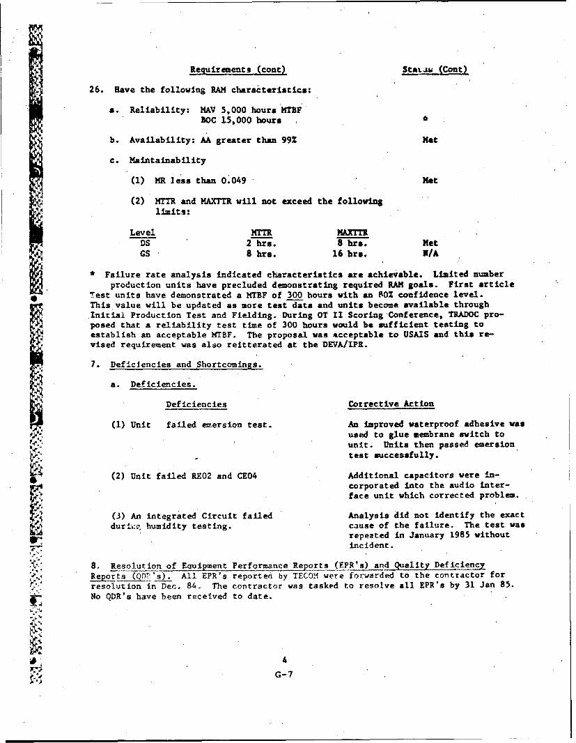
- z. *Have the following Reliability' Availabilityand Maintainability(RAM) characteristics:
(1) Reliability: The system wil have a Minimum Acceptable Value(MAV) of 5,000 hours Mean-Time-Between-Failure (MTBF) and a Best OperationalCapability (BOC) of 15,000 hours.
" (2) Availability:' The achieved availability rate.(Aa) of the systemshall be no less than 99%.
(3) Maintainability:
(a) The Maintenance Ratio (MR) should be no greater than 0.049.
5 .
C-,10
(b) The MTTR and MaxTTR will not exceed the following limits:
LEVEL MMTR MaxTTR
Direct Support 2 hours 8 hours
General Support 8 hours 16 hours
All times are exclusive of logistic support times such as travel to andfrom the service point and operational site and assumes availability ofparts and test equipment.
(c) -Scheduled maintenance requirement shall not exceed the.following:
1. Operator crew checks and service: 20 minutes per 24 hours.
2. Organizational: 2 hours per week,.(4) .~he quantitative RAM requirements contained in this LR represent
the-:bestestimate of the.operatioral. a'nd.technical requirements.,for-this. ."system ba ed upoq current available.. ndwledge; 4hiever, when --nfornatio- .is'gaindd from subsdquentstudies', trade-bffanaly!es and cost effectiveness Ievaluations that indicate a change in the need, operational/technical capa-bilities or breech of thresholds, the combat and materiel developers mayjointly initiate a change to the appropriate RAM requirement.
6. TESTING REQUIRED:
a. Critical Issues for Tests to be determined by EDT-G, EDT-C andDT/OT II.
(I , The data calculator.must be'capable of calculating ail'firing.l j• - data--Iequ-Ired to ;ly And .fi rzortae-systenis,;..-
(2)* The data 'calculator shall Accept grid "cbordinate or polar plotinformation and provide the correct mortar firing data.
(3) The data calculator must be capable of operating in'.environmentalextremes categories 1-6 as prescribed in AR 70-38 when operating with.either an external or internal power source. I
(4) The data calculator must be capable of accepting all of the abovespecified input data (paragraph 5).
5) 'The data calculator shall provide all 'of the above specified .output data (paragraph 5). '.
C-(-
n9
(6) The MFCC shall provide an increase in speed, accuracy and
responsiveness to fire requests over current fire control methods.
n (7) The Oat& calculator shall provide readout mortar firing dataSIn less than five seconds.
x (8) The data calculator, including internal power source, will behand portable and weigh no more than six pounds.
(9)- The data calculator's power source will be self-contained,throwaway and/or rechargeable and will have a life of at least 1000one-minute computations.
(10) The data calculator shall be simple enough in operation that itmay be utilized by any member of the mortar crew with a minimum oftraining.
(11) The data calculator' must be capable of storing data for eightregistration points,'up to three (3,. final.. protective fires and at least50 ieference pointk" br othere- targets (total'of 61)i .I
(13) The MFCC shall not lose stored data during che,,qing of batteries.
(14) The MFCC shall have the capability of storing ballistic data, orutilizing a conversion factor, for all known cartridge/fuze combinationsof organic mortars.
(15) The MFCC shall meet electromagnetic environmental and electro-Smagnetic pulse (EMP) requirements.. .
. b."Schedules and Mi1'e tones.:__.
Month after ProgramInitiation Milestones
. 0 LR approval and funding-authorization
* 5 Award contract for proto-type; '
16 .. R. Receive prototypes and
. .,. initiate DT II
17 Initiate OT II
20 Complete DT OT II
24 DEVA IPR
.. ... . .
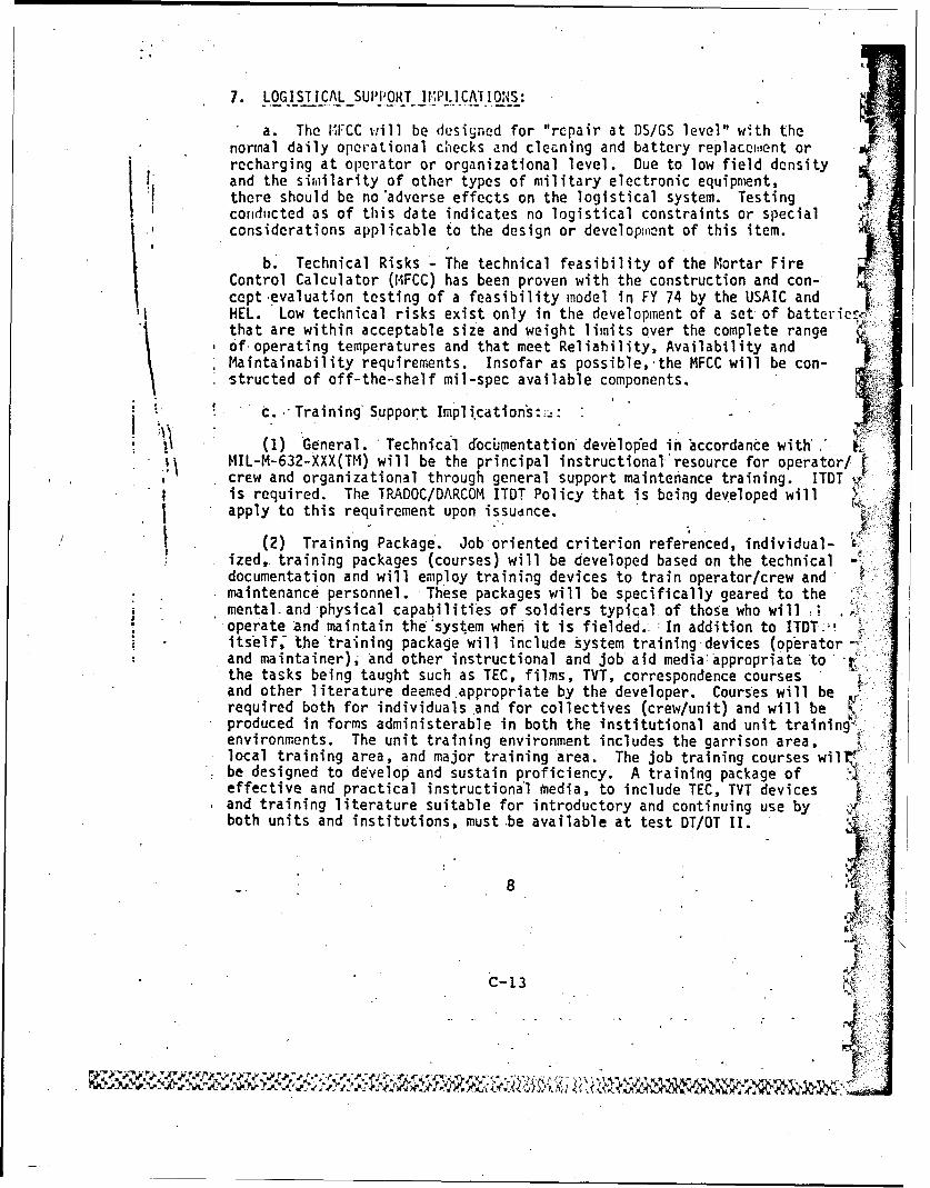
7. LOGISTICAL SUPPORT I.LICATIOiS:
a. The iFCC %..ill be designed for "repair at DS/GS level" with thenormal daily operational checks and cleaning and battery replace,,ent orrecharging at operator or organizational level. Due to low field densityand the similarity of other types of military electronic equipment,there should be no 'adverse effects on the logistical system. Testingconducted as of this date indicates no logistical constraints or specialconsiderations applicable to the design or develop~nent of this item.
b. Technical Risks - The technical feasibility of the Mortar FireControl Calculator (MIFCC) has been proven with the construction and con-cept evaluation testing of a feasibility model in FY 74 by the USAIC andHEL. Low technical risks exist only in the development of a set of battericthat are within acceptable size and weight limits over the complete rangeof operating temperatures and that meet Reliability, Availability andMaintainability requirements. Insofar as possible,.the MFCC will be con-structed of off-the-shelf mil-spec available components.
t. .- Training' Support Implications:.:
(1) General. Technical cocimentation developed in wccordance with* MIL-M-632-XXX(TM) will be the principal instructional'resource for operator/ i
crew and organizational through general support maintenance training. ITDT v.is required. The TRADOC/DARCOM ITDT Policy that is being developed willapply to this requirement upon issudnce.
(2) Training Package. Job oriented criterion referenced, individual-ized., training packages (courses) will be developed based on the technicaldocumentation and will employ training devices to train operator/crew andmaintenance personnel. These packages will be specifically geared to themental. and physical capabilities of soldiers typical of those who will .
• operate And maintain the'system when it is fielded.- : Iona to ITDT;,itself, the training package will include system training devices (operator -and maintainer), and other instructional and job aid mediaappropriate to-the tasks being taught such as TEC, films, TVT, correspondence coursesand other literature deemed appropriate by the developer. Courses will berequired both for individuals and for collectives (crew/unit) and will be Kproduced in forms administerable in both the institutional and unit trainingi,environments. The unit training environment includes the garrison area,local training area, and major training area. The job training courses wilrbe designed to develop and sustain proficiency. A training package ofeffective and practical instructiona'l media, to include TEC, TVT devicesand training literature suitable for introductory and continuing use by .
both units and institutions, must be available at test DT/OT II.
8
C-13
, kw %
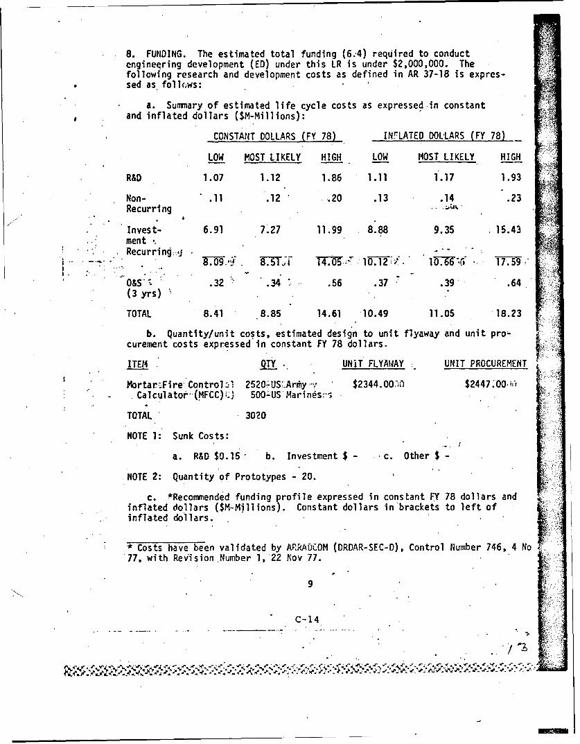
8. FUNDING. The estimated total funding (6.4) required to conductengineering development (ED) under this LR is under $2,000,000. Thefollowing research and development costs as defined in AR 37-18 is expres-sed as follo~ws:
a. Summary of estimated life cycle costs as expressed-in constantand inflated dollars ($M-Millions):
b. Quantity/unit costs, estimated design to unit flyaway and unit pro-curement costs expressed in constant FY 78 dollars.
ITEM .TY . UNIT FLYAWAY UNIT PROCUREMENT .
Mortar:Fire Control 2520US'.Arrhy $2344.00.'#: $2447.: ; -Do
* - Calculatot-(MFCC),." 5O0-US Marinds:-i,
TOTAL 3020
NOTE 1: Sunk Costs:
a. R&D $0.15 b. Investment $ - c. Other $ -
NOTE 2: Quantity of Prototypes -'20.
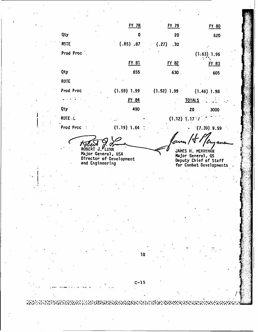
c. #Recommended funding profile expressed in constant FY 78 dollars andinflated dollars ($M-Millions). Constant dollars in'brackets to left ofinflated dollars.
Costs have been validated by AFRADCOM (DRDAR-SEC-D), Control Number 746, 4 No77, with Revision Number l,'22 Nov 77.
9
C-14
FY 78 FY 79 FY 80
Qty 0 20 620
ROTE (.85) .87 (.27) .30
Prod Proc (1.63) 1.96
FY 81 FY 82 FY 83
Qty 655 630 605
ROTE
Prod Proc (1.59) 1.99 (1.52) 1.99 (1.46) 1.98
- "FY 84 TOTALS "
Qty 490 20 3000
RDTEL . (1.12) 1.177 7
Prod Prcc (1.19) 1.64 - (7.39) 9.59
* OER . UNJAMES H . MERRY NMajor General, IUSA Major General, GSDirector of-Development Deputy Chief of Staffand Engineering for Combat Developments
10
c-15
.t Ni !.! ;
F ANNEX D
DEVA IPR RECOMMENDATIONS
FOR
TYPE CLASSIFICATION
OF
COMPUTER9 BALLISTICS: MORTAR, XM23
D-1
DIEARTh!NT OF THE ARMYWM AANEM USAEI AND DIML'OlENT COUMAND .-
9 50V W it 07/
DRDAR-SC-Xm23 I July 1981
SUBJECT: DEVA IM Recommendations for Type Classification of theComputer, Ballistics: Mortar. XKO23 (FCC)
CommanderU.S. Army Materiel Development aid
Readiness CommandATTN: DRCD-
- 5001 Eisenhower AvenueAlexandria, VA 22333
Torvarded for approval are the recommendations of the Computer,Ballistics: Mortar, XM23 (FCC) DEVA IPR held on 1 July 1981.
1. A Development Acceptance In-Process R viev (DEVA-IPR) was held onI July 1981, resulting in a 4etermlnation that the Computer, Ballistics:,Mortar, MM2:
a. Is acceptable for the 3isson intended.
b. Does meet regulatory prerequisites for entry into the ArIUventory.
e. Is required, In limited quantity (468) for a limited tim (throughSep 1983) for an urgent operational requirement uhich vil allow thecurrently scheduled IOC date to be met and vill expedite getting anurgently needed system Into the hands of soldiers in the field.
d. Is safe for all aspects of ude (Safety and Bealth Dara Sheetattached).
2. Accordingly. recommend the Item/system be type classified Limited IProcurement (LCC-1).
3. Replacement information: None
4. Specific end item recommended for type classification:
a. Federal Item Identification: 1220
b. LIN: ZL7218
c. NSN: NTA
d. RiCC: ETA
e. Type classification; Limited Procurement (LCC-U) If. BOIP number: 78-00187
g. Requirement: Letter Requirement (LR) for Mortar Fre ControlCalculator (MFCC), USATRADOC ACN 16906, dtd 30 December 1977.
LTC , IN . IPR C A N
STEVE R. GTB* DAC CS-11 US S
. RONA.D L. DOYLEUSALEA
DEDAR-SC El_____________
SUIEC: Materiel Statusa Record Submission
TO: DeadquartesU.S. Army Materiel Development
and Readiness CommandATTN: DRCDE-A?3001 Eisenhower AveuAlexandria, VA 22333
Coputer, Ballistics: Mortar, MN3
Together with the attached documents, are forwarded for recording In
the Materiel Status Record In accordance with AR 70-2:
CENRAL INFORMATION:
a. Project/Task Title: Computer, Ballistics: Mortar XK23(Mrtar Fir* Control Calculator).
b. Program Element: 6.47.25.A
c. Project/Task Niumber:. 1W464727AS7000
d. CAMD Paragraph Reference: 1121
a. Previously Recorded Item Nuibers: None
f. LIN: Z17218
S. 1SN: to be assigned at a later date
mY?z cLAss11cATiOm/Rr.CLASsiFIcATz0N
a. Item: Computer. Ballistics: Mortar. 1MW
b. Date of Review: 1 July 1981
c. TC Decision: XR423 TC LCCU to 2123
4.Other Decisions: None
a . Approved by: Date:
D-4
3RDAR-SCSUaJEC: -Material Status Record Suhmiusiou
PREPARED BY:
Office:
Namn of Contact: J.A. Schultz Telephone: AUTOVOK S80, tLId6l9
3 Incl1. LU., DRCDE, 1 July 19812. DEIVA Ifl Mnutea* I July'19813. TC Recomendation. 1 July 1981
2
D- 5
DEVA um mIUTES
IDAM I July 1981
IURFOSE: M423 DEVA 171 to Establish DEVA Wk Recoumendation
ATTENDEES: See Inclosure I
1. The XH23 DEVA IPR was held at ARRADCOM on I July 1981 and was chairedby LTC David W. Logan. Names of attendees are provided at Inclosure 1;voting members are preceded with an asterisk.
2'0 A copy of the presentation given by Mr. J.A. Schitz, DPO, XM23 Isattached as Inclosura 3 Recomended improvements introduced as a resultof discussions during the meeting have been incorporated via hand-writtenadditions. It was the concensus that these improvements are of acceptabletechnical risk and could be Incorporated into the unit during the nextcontractual phase.
3. The TECOMf representative, via FONECON, recommended In light of theplanned ispMements to eliminate the battery adapter wand and the V-iwire adapter with case Integral connectors, that testing of these itemsbe delayed until these improvements have been incorporated into the unit.'Testing then could be accomdated during the First Article - InitialProduction Test (FA-IPC). Recomendatioo accepted.
4. The following factalclarification were Identified for considerationby the User in regard to a review of the Letter Requirements (LX) andthe XK23 capabilities.
a. Ref LRSg(12) the word "canister" will be changed to the word "dud".The XK23 computes dud range and impact coordinates for the 81mm and 4.2"illumination rounds. One of the software improvements to be incorporatedInto the unit Is to provi e the added capability to calculate the range/Impact coordinates for the 60mm illumination rounds.
b. Ref LX 5k Verification and correction of operator entered datawill be possible even after the calculation has been completed. Thisimprovement will be incorporated during the next contractual phase.
c. The wording in LR pare 51 will be changed to reflect that mortarmen trained in Fire Direction (FDC) Operation should be able to operatethe XH23 with minimum training, as opposed to stating that any member ofthe mortar crew can operate it with minium training.
,-
', /_D-6
, .
O.VA l MNUTES
(cont'd)
5. The urgent requirement reflects the quantity needed tz equip key Rapid'Deployment Force units and establish a training 'base, plus 30Z additionalfloat quantity for support. --
6. TRADOC representatives recow-ended that a IOC FDTE be conducted. Thisis presently In the program schedule.
7. LEA representative Identified a need for maintenance floets/DX quantitiesbe Included In the procurement quantity. (Para 5 above addresses these
S. Logistic Support Milestones vill be finalized by 3rd qTR, FY82. LSelement milest"nes will be published in an updated Logistic Support lanto establish logistic support vhen items are type classified standard.
9. The DEVA XPR reccr.endation is at Inclosure 2.
2 Imcl
P,.lARED XT: £ 4Mr JOSEP A. SCITZDP XM2 3
ODNCURRD:LTC IN. CHAIRAN"
STEVE - . CgO
AON.I. L. DOYLEI. USALEA,
2
D-7
..... .....
DEVA In RECOtOENDATION
THE COMPUTER, BALLISTICS: MORTAR XM23
1. The Computer. Ballistics: Mortar XH23 (McC) essentially meet* therequirements delineated In the Letter Requirement (LR) against which itwas evaluated.
2. The XK23 is acceptable for calculating Infantry mortar systems fir-In& data, (60m, Sum, and 107mm mortar systems) and should be classifiedas Limited Production (1CC-U). The XH23 is acceptable for intro-duction into the Army inventory after the improvements listed In Para 3are incorporated into the system, vhich can be accomplished duringlimited production without further development effort.
3. The following improvements vill be incorporated into the XM23 systemprior to fielding:
TR X WARE
a. Add voltage protection circuit for protection against excessivevoltages.
b. Insure minimum of 501 reserve memory for future expansion after4 new rounds have been incorporated (see par& 3h below).
c. Prevent data loss Vhen low voltage indicator light comes on.
,.d. Provide for operation vith primary and secondary (rechargeable)batteries.
e. ElImInatu the need for separate 214 vire adapter with case in-tegral connectoz.
f. Replace 11-1 "Fig Tall" with case integral connector.
g- Eliminate the battery adapter vand..
SOFTWARE
b. Program 4 new rounds into XH23 04374A3. XM630, M33SA1, M329A2).
i. Provide dud Illmination round Impact point and warning fire zoneviolation for 60me.
*~ 0-8
S
DEVA IPR RECOMENDATION
FOR
THE COMPUTER, BALLISTICS: MORTAR XH23 (Cont'd)
1. Delete 2nd application of adjustment during shift mission.
k. Provide operator override to change selected charge (60/81mm)and selected elevation (4.2") program to apply registration correctionto 1'PF.
" 1. Lift restrictions on mortars to permit deflection capabilityof 6400 als&.
a. Implement changes specified in OTII IER Par 7b. 71 and 7n.
a. Lift max range restrictions of 60mm to calc. Max range for maxcharge.
o. Include conversions for ammo vt. (lbs/squares), alt. (ft/metevs),muzzle velocity (ft/sec or m/sec) , training rounds (decimeters).
p. Capability to review and correct all data even after calculationIs completed.
q; Incorporate a standby indicator.
r. Abi ty "to.correct OT direction if GT switch Is incorrectly.pushed when computing grid mission.
s. Iuplemeut MPI registration procedure.
t. Display warning when friendly positions are entered as targets.
u. Program calculator to converge sheaf when desired in fire forelfect.
4. It Is agreed that the vording in the LR, Para 51, be shanged to reflect
that mortar men trained in Fire Direction Center (FDC) Operation should beable to operate the Y423 with minimum training. Other LR requirements not
met are considered waived for TC-LPU. Consideration will be given toproviding keyboard illumination at no trade off of battery life.
2
D-9
DEVA IPR RECOMMENDATION
701
KY THE CMIPUTER, BALLISTICS: MORTAR XM23 (Cont'd)
5. The above position has been reviewed and concurred In by the undersigned.
CONCURRENCES.
DVID W. LOGANS LTC, IN, IPR CRAIRMAN
DAC CS-11 USAIS
RONALD L. DOYLEj USALE&A
.
. D-I10
AJ"
ANNEX E
PRODUCT IMPROVEMENTS IDENTIFIED IN THESCOPE OF WORK SECTION OF PRODUCTION CONTRACT
E-1
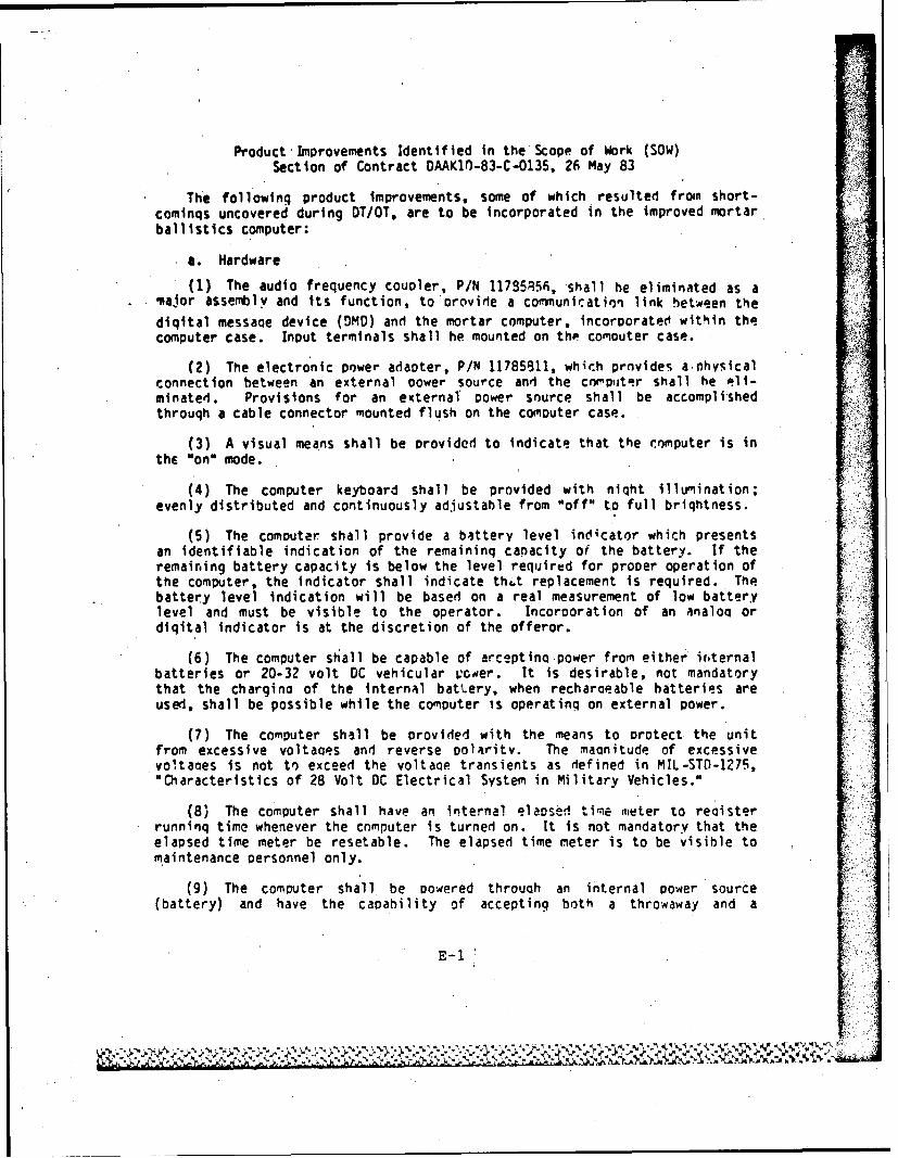
Product'Improvements Identified in the Scope of Work (SOW)Section of Contract DAAK1t-83-C-0135, 26 May 83
The following product improvements, some of which resulted fron short-cominqs uncovered during DT/OT, are to be incorporated in the improved mortarballistics computer:
a. Hardware
(1) The audio frequency coupler, P/N 117S5856, shall he eliminated as amnajor assemlyv and its function, to orovide a connunication link hetween the
diqital messaqe device (DMD) and the mortar computer, incorporated within thecomputer case. Input terminals shall he mounted on the comouter case.
(2) The electronic power adapter, P/N 11785S11, which provides a nhvsicalconnection between an external Dower source and the cnmouter shall he eli-minated. Provisions for an external Dower snurce shall be accomplishedthrouqh a cable connector mounted flush on the computer case.
(3) A visual means shall be provided to indicate that the computer is inthe "on" mode.
(4) The computer keyboard shall be provided with niqht illumination;evenly distributed and continuously adjustable from "off" to full brightness.
(5) The computer shall provide a battery level indicator which presentsan identifiable indication of the remaininq capacity of the battery. If theremaining battery capacity is below the level required for proper operation ofthe computer, the indicator shall indicate thut replacement is required. Thebattery level indication will be based on a real measurement of low batterylevel and must be visible to the operator. Incorporation of an analoo ordiqital indicator is at the discretion of the offeror.
(6) The computer shall be capable of arceptino power fron either itternalbatteries or 20-32 volt DC vehicular power. It is desirable, not mandatorythat the chargino of the internal battery, when recharoeable batteries areused, shall be possible while the computer is operating on external power.
(7) The computer shall be orovided with the means to protect the unitfrom excessive voltages and reverse polarity. The maonitude of excessivevoltaoes is not to exceed the voltaqe transients as defined in MIL-STO-1275,"Characteristics of 28 Volt DC Electrical System in Military Vehicles."
(8) The computer shall have an internal elapsed ti.e meter to reoisterrunning time whenever the cnmputer is turned on. It is not mandatory that theelapsed time meter be resetable. The elapsed time meter is to be visible tomaintenance personnel only.
(9) The computer shall be powered throuqh an internal power source(battery) and have the capability of accepting both a throwaway and a
E-1
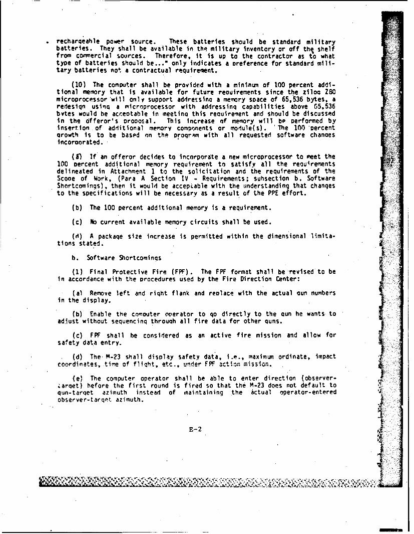
recharqeahle power source. These batteries should be standard militarybatteries. They shall be available in the military inventory or off the shelffrom comercial sources. Therefore, it is up to the contractor as to whattype of batteries should be..." only indicates a preference for standard mili-tary batteries not a contractual requirement.
(10) The computer shall be provided with a minimum of 100 percent addi-tional memory that is available for future reouirements since the zloo Z80microprocessor will only support addre.sino a memory space of 65,536 bytes, aredesiqn usinq a microprocessor with addressinq capabilities above 65,536bytes would be acc.eotable in meetinQ this recuirement and should be discussedin the offeror's orooosal. This increase of memory will be performed byinsertion of additional memory comprnents or module(s). The 100 percentarowth is to be based on the oroqr~m with all requested software chanoesincoroorated.
(&I If an offeror decides to incnrporate a new microprocessor to meet the100 percent additional memory requirement to satisfy all the reau'rementsdelineated in Attachment 1 to the solicitation and the requirements of theScooe of Work, (Para A Section IV - Requirements; suhsection b. SoftwareShortcomings), then it would be acceptable with the understanding that chanqesto the specifications will be necessary as a result of the PPE effort.
(b) The 100 percent additional memory is a requirement.
(c) No current available memory circuits shall be used.
(d) A package size increase is permitted within the dimensional limita-tions stated.
b. Software Shortcominqs
(1) Final Protective Fire (FPF). The FPF format shall be revised to bein accordance with the procedures used by the Fire Direction Center:
(a) Remove left and right flank and replace with the actual aun numbersin the display.
(b) Enable the Comouter operator to qo directly to the Qun he wants toadiust without sequencing through all fire data for other quns.
(c) FPF shall be considered as an active fire mission and allow forsafety data entry.
(d) The M-23 shall display safety data, i.e., maximun ordinate, impactcoordinates,• i ^f fl in i , e . Ifow- F F ..... i,,----o--
(e) The computer operator shall be able to enter direction (observer-&arqet) before the first round is fired so that the M-23 does not default toqun-tarqet azimuth instead of maintaining the actual operator-entered 4,observer-tarqet azimuth.
E-2
WM r YI
f) The computer operator shall have the capability of adiustinq thecharge durinq final protective fire (FPF). The comouter-selected charqp forFPF for the 60mn and Alm mortars cannot be manually channed hy the operator.If adjustments to the FPF exceed (oo above or below) the pre-selected charqe,the mission must he ended and a new mission started.
(a) Mortars do not use time corrections fnr rewistration, but do dif-ferentiate shell/fuze types for reoistration. The firino tahles, not the FM(field manual) indicate how these corrections are to be applied.
(2) Deflection Limitations
(a) The 4-23 proaral- shall be revised so th'at all aroLn3-TijnteM mortarsare capable of firing in a 6400 mil circle.
(b) The 107mn (4.2 inch) carrier-mounted mortar shall have a 1600 miltraverse limit from mounting izi-utj'n as follows: 825 mils riqht and 775 mils
(c) The M-23 shall be oroaranned to apply muzzle velocity corrections tocarrier-mounted (81m and 107mm) mortars.
(3) Mission Switch Abbreviations, When the "mission" switch is acti-vated, the display shall display "UNA" %Unassigned) to be compatible with thedisplay "UNASSIGNED" when the display switch is depressed.
(4) Survey Shortcomings
(a) Intersection. The M-23 shall be reproorammed to display "NO TRI-ANGLE" when two non-intersectina azimuths are entered oy the operator.Presently, the compoter Qenerates a resection (an intersection in the oOositedirection) i.e., when the same FO (Forward Observer) is used to enter twodifferent azimuths, the M-23 will display the location of the FO alreadyassiqned.
(h)' Resection. The M-23 shall he reproqrammed to display "NO TRIANGLF"wnen two azimuths are entered by the operator which will not resect. Pre-sently, the M-23 reverses the direction of the entered azimuths and generatesan intersection.
(c) Traverse. The M-23 shall be reoroqrammed to permit traverse to con-tinue: after the base mortar is entered by the operator. Presently, traversewill only continue if points are stored as target (TGT), known point (KNPT),and forward observer (FO). If base mortar is stored, the traverse stops;operator shall have the option of storing TGT, KNPT, FO and RP (basepiece) inany sequence.
(5) Illumination Safety Diagram. The M-23 shall be reprograwned to com-pute and display both burst coordinates and the impact coordinates and displaya safety violation if the impact point is outside the safety diagram.
E-3
lltl 1%
The M-3 now disolays a safety violation only if the burst is out of thesafety diagram. In many cases, the planned burst is within the safetydiaoram, but if the round fails to function, the tralectory of the round isSuch that the round will impact the ground outside the safety diagram.Current FOC (Fire Oirectinn Centpr) procedure is to construct the safetydiagram at range to impact for maximum range.
The terminology in the M-23 shall be redefined to indicate that the impactpoints are the burst coordinated and the canister points are the impact coor-dinates if the round fails to function properly. The intent is to keep bothHE (Hiqh Exolosive) and ILLUM (Illumination) rounds within the safety limitsat maximum range only. The program shall not be altered for minimum range incommparinq the safety diagram with the burst coordinates.
(6) Safety Data. Safety diagrams for the M-23 are applJed to the basemortar only. The safety diagram may be different for other mortars in themortar platoon, therefore, the M-23 shall be reprogrammed to allow the opera-tor to enter safety diagrams for each mortar associated with the base mortar.
(7) Backstep Capability. The M-23 shall be reprogrammed to allow theoperator to hackstep throuqh each step of an operation in order to make cor-rectinns. The M-23 reveiw capability is litrited At present to backsteppinqone step of an operation of sequencing ahead to a desired ooint.
(8) Special SheafParallel Sheaf Corrections
(a) Soecial Sheaf. The M-23 shall be reproorammed to follow the FPF(Final Protective Fire) sequence for special sheaf.
(b) Parallel Sheaf. The M-23 shall he reprogrammed to allow adiusL-, ntof parallel sheaf after the registration is completed by the base mortar.
(g) Surveyed Points As References. The M-23 shall be reprogrammed sothat when an engaged tarqet is a surveyed point, and the mortar position is asurveyed point, the rounds for FFE (Fire For Effect) shall impact at the ori-qinal surveyed grid point. When a converged sheaf is selected by the opera-tor, the 100/R used to close the sheaf shall be taken from the range to thesurveyed point.
(I0) Converge Mission. The M-23 shall be reorogrammed so that the capa-bility for convergence is selectahle by the operator throughout the entiremission. At present, if the *converge" switch is not selected at the begin-ninq of a fire mission, the M-23 will not allow the operator to select itduring the mission. Concurrently, the DST (Destruct) operation, displayedunder the TFC (Technical Fire Control) switcli, shall be programmed to convergeall mortars firing onto the target.
v4:
F, "7
(11) Non-Convergent Mission. The M-23 shall be reproqrammed to eliminatethe followinq operational shortcominq: when firinq a polar mission, the 14-?3will display initial firinq data and first syubsequent Adjustment. Howpvor,when a second subsequent adjustment is entered, the M-Z3 displays NON-CONVER-GENT'. Depressino the *COMPUTE" switch a second time for this adjust(cit,will display the desired firinq data. Further, the term "NONCONVERGENT" ismeaninqless to the computer operator and shall be eliminated.
(12) Vertical Interval (VI) Between Tarqet and Mortar Locations. Whenthe difference in altitude (VI) between tarqet and location is extreme, theM-23 displays "BAD HEIGHT0. The M-23 is pronrammed with. limitations on themaqniture of VI for which it will provide a correction. Reprorainlno isnecessary because:
(13) Minimum Firin Elevations. The M-23 shall he reoroqrammed so thatfirina data is not disolaved for elev3tions less than 8O mils. When thiscondition occurs, the comouter shall display "ELEVATION TOO LOW".
(14) With and Without Extension (107mn). The M-?3 shall be reproarammedto provide the capabilitv of chanoino from "with exension" to "without exten-sion" during subsequent adjustments of a mission in proqress.
(15) Charge Change (81. m). The M-23 shall be reproorammed to provide thecapability of changing "cnarges" durlnq adjustment of a mission in proqress.
(16) Weignt Corrections, Grid Declination, Grid Zone, Latitude Data.Discreancies in tnese data elements between the M-23 and firinq tables are astolli)is:
(a) Weight Corrections. 8mn and 60mm ammunition is computed as onestandard weight. The M-23 allows for weight corrections under the "AI1MO DATA"switch; however, the firinq tables do not give data for these corrections.The 107mn Illumination round is not "squared" as the HE (High Explosive) andWP (White Phosphorous) rounds are. The M-23 allows weiqht corrections to beapplied to illumination rounds to compensate for differences in muzzle velo-city; again no data in this regard are contained in the firinn tables. There-fore, weiaht corrections, which .cannot be correlated with oublished firinatables, are to be deleted from the M-23 proqram.
(b) Grid Declination. Grid declination variations do not affect firedata'or any of the options under "survey": switch (intersection, resection, ortraverse) and can 'e deleted from the M-23.
(c) Grid Zone. Grid zone remains as %tandard and cannot be manuallychanged, and can be deleted from the M-73.
(d) Latitude Data. Latitude data is a mandatory entry for the M-23 andcannot be bypassed. This information has b minimal effect on fire data atmaximum ranqe and can be delete(; from the M-23.
E-5
(17) Reaistration (Survey Grid). Reqistrations are conducted by firtnofrtm one survey point to another. After firina reqistration and the registra-tion corrections are determined, the M-23 Presents the option EOM (End ofMission) or EOMRAT (End of Mission Record As Taroet) under the OEOM" switch.If the operator selects the EOMRAT, the M-23 records the grid coordinates ofthe final plot with all the subsequent corrections included. This is not thelocation of the target registration point (RP). When the forward observer(FO) decides to use this RP to shift onto another tarqet, the M-23 will applythese new shift corrections to' the final plot. The M-23 shculd be using thesurveyed grid and not the final plot to be shifting onto the new tarqet.Therefore, the M-23 shall be reproqrammed to record the surveyed qrid coor-dinates as the tarqet when a reqistration is completed.
(18) Temperature (17nmn) The firing' tables for the 107, state thatrounds are not to be fired with extension below -30F. The M-23 shall bereproramed to give warninq that "TEMP TOO LOW" to fire this mission withextension at that elevation.
(19) Elevation Default (107m). The M-23 now defaults to elevation 900-ils for all missions; operators must either stay with default elevation, ordetermine the elevation chanqe required to fire the mission. The M-23 shallbe reoroqr&-ined to select one of the three possihle elevations (0800, 0900,1065 mils) to fire mission, i.e., if proqramied to qive the lowest elevaticnand the display indicates "RANGE TOO BIG" then the tarqet if out of ranqe; ifat the hiQhest elevation the display indicates "RANGE TOO SMALL", then theround cannot reach the tarqet.
(20) Cartridne-Fuze-Charqe Combinations. The M-23 shall he reorogrammedti display "CHARGE VIOILATION" when computinq firing data under the followinig"conditions:
(a) S1mm cartridaes are used with fuze, VT, M532 at charge 0.
(o) lO7m cartridqes are used with fuze, VT, M513, MS13A1, M513A2, orM51381 below 10 increments.
(c) 1On1m carrier-mounted, when firing above 32 at an elevation of 1065mils
(21) Mission Format Sequence. The M-23 shall be reprogrammed so thatafter "TFC" (Technical Fire Control) mission is selected, the operator shallbe directed to enter "WPN/A MO" data which was omitted instead of defaulting .to "READY" i.e., after a GRID, POLAR or SHIFT MISSION is selected, the M-23
displays "NO WPN DATA" then default to the data entry that was missed by theoperator.
(22) Minimum Ranqe-Illumination. The M-23 shall be reproqrammed to pro-Avid,' the capability of firinq illumination at the minimum ranne as listed inthe respective firlnq tahles. In this reqard, the M-23 shall display "TGTLOW/RNG SMALL" for ranqes less than minimum.
E-6
&AN
(23) Reqistration Corrections. The computer when calculating data for aShift mission from a target previously engaged with reoistrat ion corrections,applies the registration corrections twice. This condition 'Shall be elimii-nated since the FFE (Fire For Effect) mi'ssion, without fire conducting andadjustimenti the target would be missed by tIhe range and deflection distanceresulting from those corrections.
%'24) Weight Corrections (107am). The M-23 shall be reprogrammed so as topr0viie the operator with the capability of entering projectile weight in"sq .3res" or *pounds" to ohtain the range correction due to nonstandard pro-,jectile weiqht.
(25) Muzzle Velocity, Altitude Data and Recall. The M-23 shall be repro-aramoted to provide the computer operator with the following capabilities:
(a) Muzzle velocity. Muzzle velocity variations for ranne correction, shallhe entered in either meters per second or feet per second.
h)Altitude.' Altitude data for firing correction shall- be entered ineitner meters or feet.
(c) Recall. The rer~all caoability to review datai that has been enteredinto the M-23, shall be retained after the "COMPUTE" switch has been acti-vated.
U(26) Maximum Range - Marlmwt Charge. The M-23 shall be reprnqrafwed toU com-ite 'Paximunl r3nqe with -naxi ,t charge for all mortars.,
(27) Observer-Tarqet (OT) Azimnuth. The M-23 shall be reprogramm~ed toretain the entered OT azimuth, (entered when initiating the *SHIFT" or "GRID"mission), so that any subsequent adjustments are made relative to the OT lineand not the oun target (GT) line. In the present progr3mf, the M-23 defaultsto the GT azimuth.
(28) MPI (Mean Point of Impact). The M-23 shall be reorograinmei toimple-nent the MPI format. The MPI registration 'nav be used to deter-nineeitner initial fir4ng corrections or updated corrections from earlier renis-tration or application of MET (Meteorological) corrections. Method and oro-cedures are discussed in the FM (Field Manual).
3(29) Friendly Positions. The M-23 shall be reorocirzmed to display awarning if friendly positions are stored in the computer as targets. Thiswarnind shall be proqranmned on a radius rather than exwt l'ncation: thelatter would be within the bursting radius of a round of ammrunit i. The M-23shall still compute and display fire data as it currently does a~r fire lineand zone violations.
E-7
(30) Safety Data. 'Safety diaorams for the 14-23 are applied to only one.iortar location. The 14-23 shall be reprograimied to apply safety. diagrams forall mortar sections since the safety diagram may be different for other mo~r-tars in the mortar platoon.
(31) Additional Mortar Round%. The M4-23 shall be program, ~d to computefiring data for the followinq additional mortar rounds.
81m mortar HE, M374A3107.. mortar HE, M329A2
CS, X4630
E-8
I ANNEX F
COMPUTER RESOURCES, MANAGEMENT PLAN (CRMP)
FOR THECOMPUTER, BALLISTICS: MORTARO M23
(FINAL DRAFT)
F-i
I
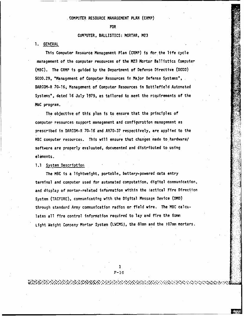
COMPUTER RESOURCES MANAGEMENT PLAN (CRMP)
FOR THE
COMPUTER, BALLISTICS: MORTAR,' M23
US ARMY ARMAMENT MUNITIONS, AND CHEMICAL COFIIAND
US ARMY ARMAMENT RESEARCH -AND DEVELOPMENT CENTER
F-2'U
'4[ .
ABSTRACT
This Computer Resources Management Plan (CRMP) identifies important
computer resource acquisition and life cycle planning factors and establishes
specific guidelines to ensure that these factors are adequately considered in
the acquisition planning prccess of the Mortar Ballistics Computer, M23. In
addition, this plan establishes the necessary framework and support system for
sofA.ware configuration management during production, test, evaluation, and post
deployment.
F-3
NTABLE OF CONTENTS
Section Title Page No.
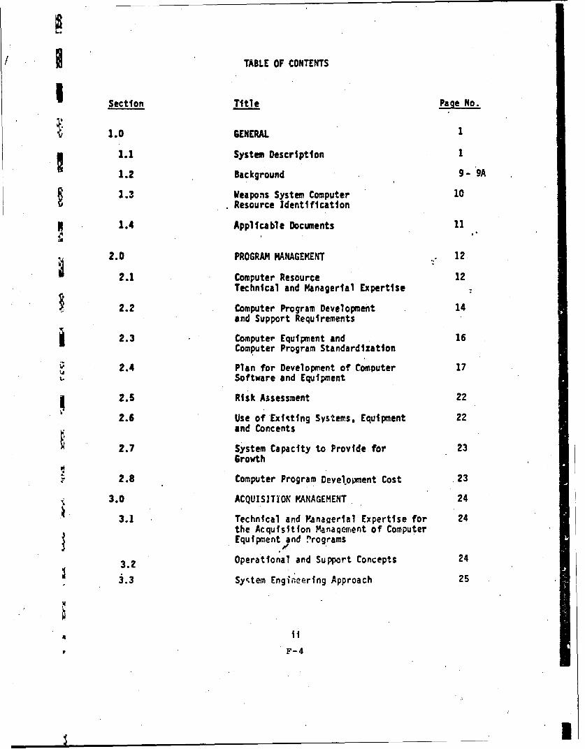
1.0 GENERAL 1
1.1 System Description I
1.2 Background 9- 9A
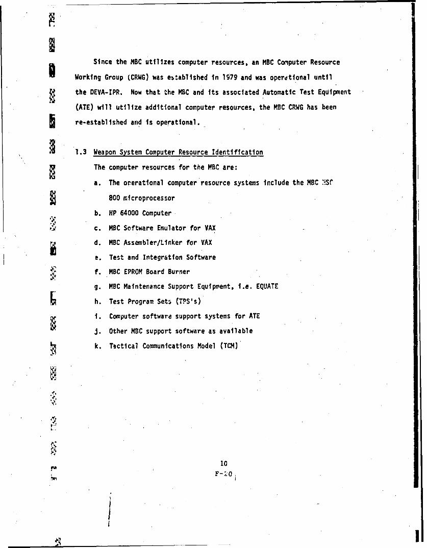
2.3 Weapons System Computer 10Resource Identification
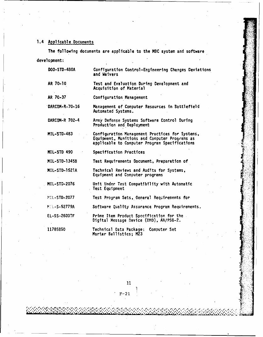
1.4 Applicable Documents 11
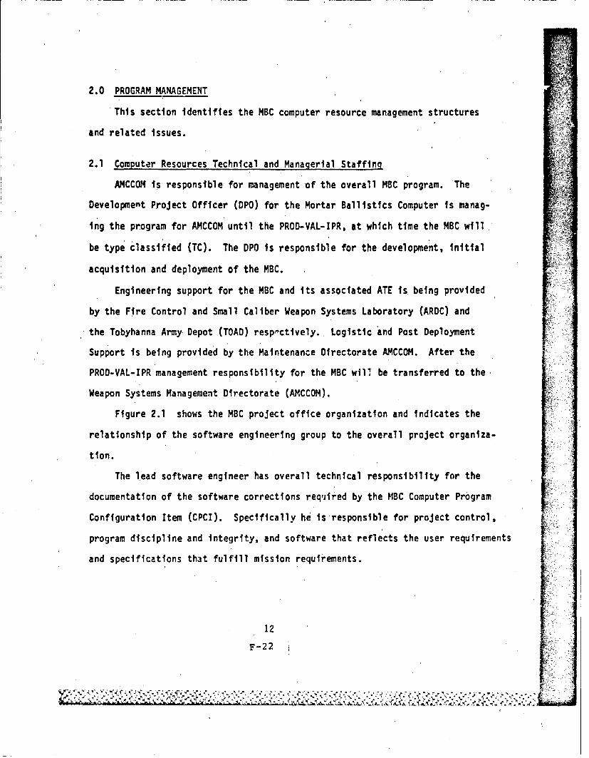
2.0 PROGRAM MANAGEMENT 12
2.1 Computer Resource 12Technical and Managerial Expertise
2.2 Computer Program Development 14and Support Requirements
j 2.3 Computer Equipment and 16Computer Program Standardization
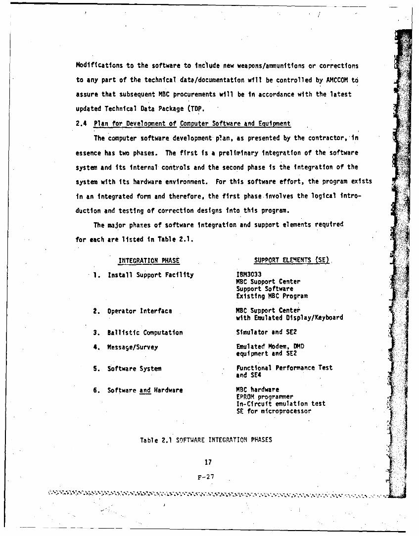
2.4 Plan for Development of Computer 17Software and Equipment
2.5 Risk Assessment 22
2.6 Use of Existing Systems, Equipment 22and Concents
2.7 System Capacity to Provide for 23Growth
2.8 Computer Program Development Cost 23
3.0 ACQUISITION MANAGEHENT 24
3.1 Technical and Vanagerial Expertise for 24the Acquisition Management of ComputerEquipment and nrograms
3.2 Operational and Support Concepts 24
3.3 System Engineering Approach 25
F-4
_ _'I,
II
(TABLE OF CONTENTS (Cont'd)
Section Title Page No.
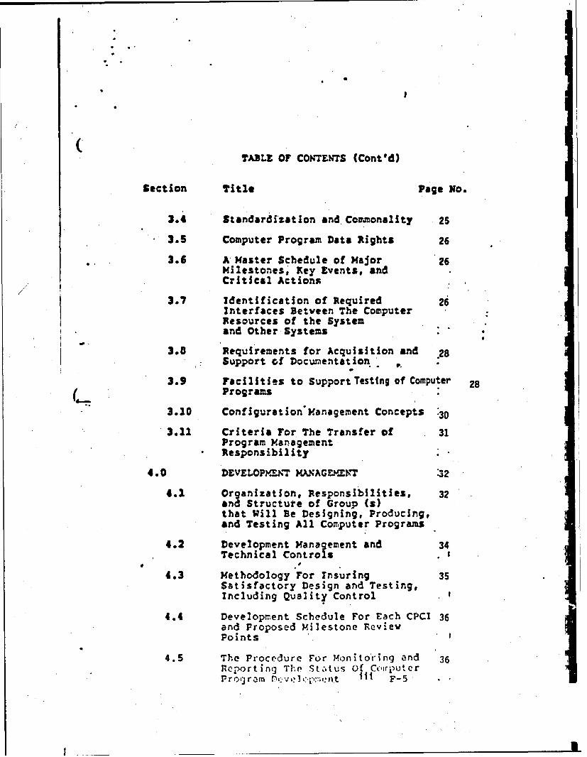
3.4 Standardization and Commonality 25
3.5 Computer Program Data Rights 26
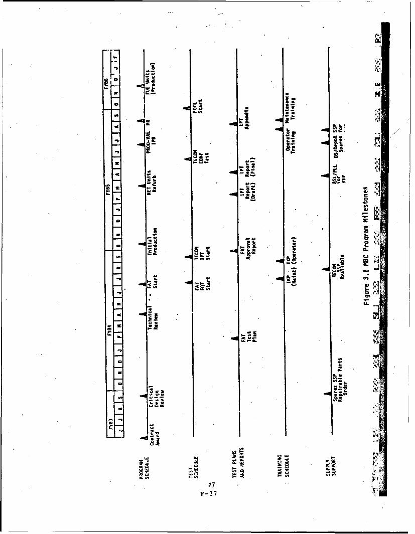
3.6 A Master Schedule of Major 26Milestones; Key Events, andCritical Actions
/ /
3.7 Identification of Required 26Interfaces Betveen The ComputerResources of the Systemand Other Systems
3.8 Requirements for Acquisition and .28Support of Documentation
3.9 Facilities to Support Testing of Computer 28(,._ Programs
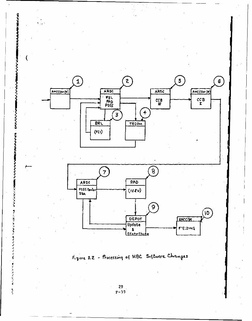
3.10 Configuration'Management Concepts :30
3.11 Criteria For The Transfer of 31Program ManagementResponsibility
4.0 DEVELOPYXNT MJANAGEP-XVT 32
4.1 Organization, Responsibilities, 32and Structure of Group (s)that Will Be Designing, Producing.and Testing All Computer Programs
4.2 Development Management and 34Technical Controls .
p
4.3 Methodology For Insuring 35Satisfactory Design and Testing,Including Quality Control
4.4 Development Schedule For Each CPCI 36and Proposed milestone RevievPoints
4.5 The Procedure For monito'ing and 36R eporting T he Status Of CoirputerProtj3ra P,?";,: ,:, n::';,nt iii F-5
S *1I.
TABLE OF CONTEN7S (Cont'd)
Section Title Page No.
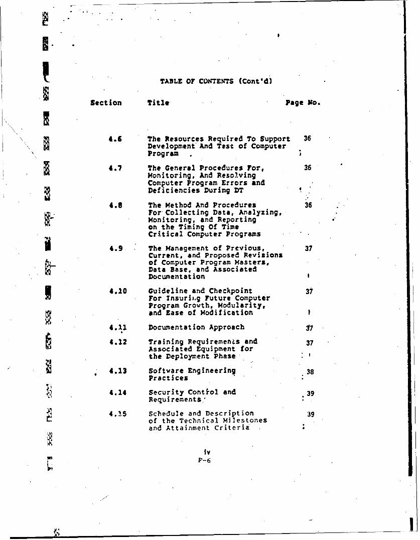
4.6 The Resources Required To Support 36
Development And Test of ComputerProgram
4.7 The General Procedures For, 36Monitoring, And ResolvingComputer Program Errors andDeficiencies During DT
4.8 The Method And Procedures 36For Collecting Data, Analyzing,Monitoring, and Reportingon the Timing Of TimeCritical Computer Programs
4.9. The Management of Previous, 37Current, and Proposed Revisionsof Computer Program Masters,Data Base, and AssociatedDocumentation
4.10 Guideline and Checkpoint 37For Insurit.g Future ComputerProgram Grovth, Modularity,and Ease of Modification I
4.11 Documentation Approach 17
4.12 Training Requirements and 37Associated Equipment forthe Deployment Phase
" 4.13 Softvare Engineering 38Practices
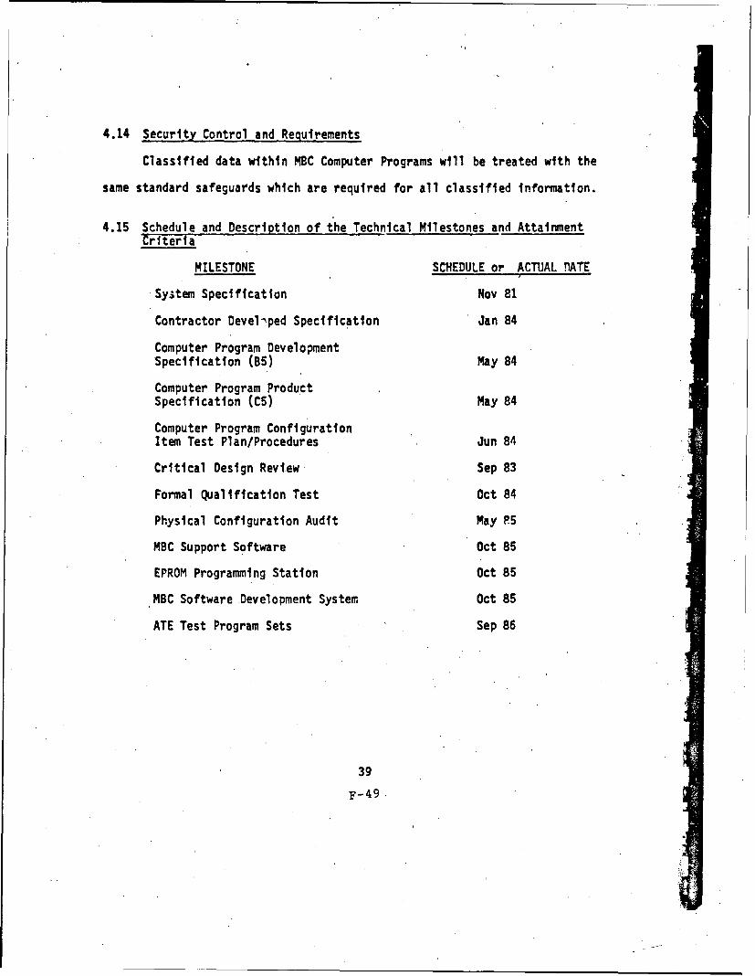
4.14 Security Control and .39Requirements.'
4.15 Schedule and Description 39of the Technical Milestonesand Attainment Criteria
ivF-6
TABLE OF CON~TENTS (Cont'd)
Section Title Page N1o.
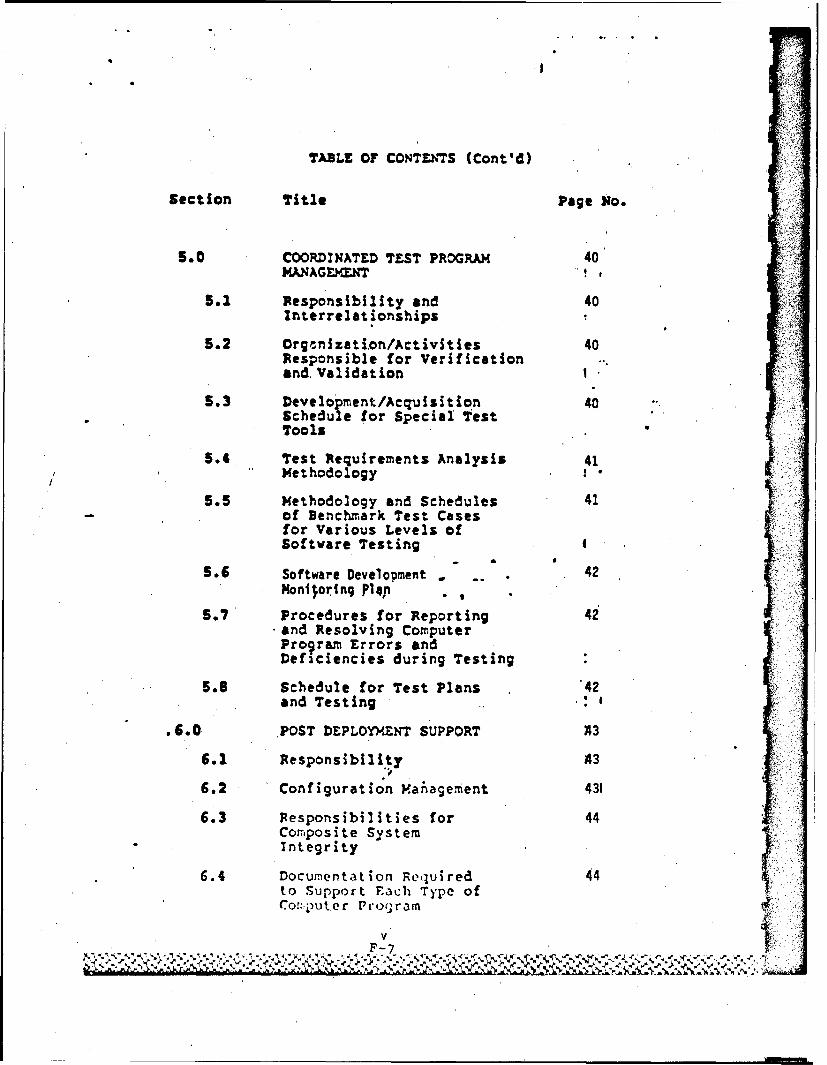
5.0COORDINATED TEST PROGRAM 40MANAGE~rXT
5.12 Responsibility and 40interrelat ionships
5.2 Orgonnization/Activities 40Responsible for Verificationand, ValidationI
5.3 DevelopmentfAcquisition 40Schedule for Special testTools
5.4 Test Requirements Analysis 41Methodology
5.5 Methodology and Schedules 41- of Denchmirk Test Cases
for Various Levels ofSoftware Testing 4
5.6 Software Developmnent -- 42lHonijoring P1 4P
5.7 Procedures for Reporting 42and Resolving ComputerProgram Errors andDeficiencies during Testing
5.8 Schedule for Test Plans 42and Testing .
.60POST DEPLOYMENT SUPPORT A
6.1 Responsibility 4
6.2 Configuration Vafhagement 431
6.3 Fesponsibilities for, 44Com'posite SystemIntegrity
6.4 Documentation Required 44V
to Support Fach Type ofCor:puter Pr')jr3mn
TABLE OF CONTENTS (Cont'd)
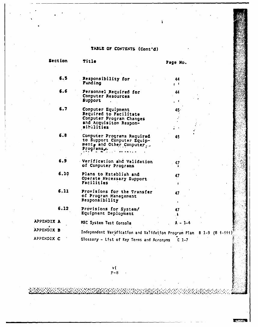
Section Title Page No.
6.5 Responsibility for 44Funding a
6.6 Personnel .Required for 44Computer ResourcesSupport
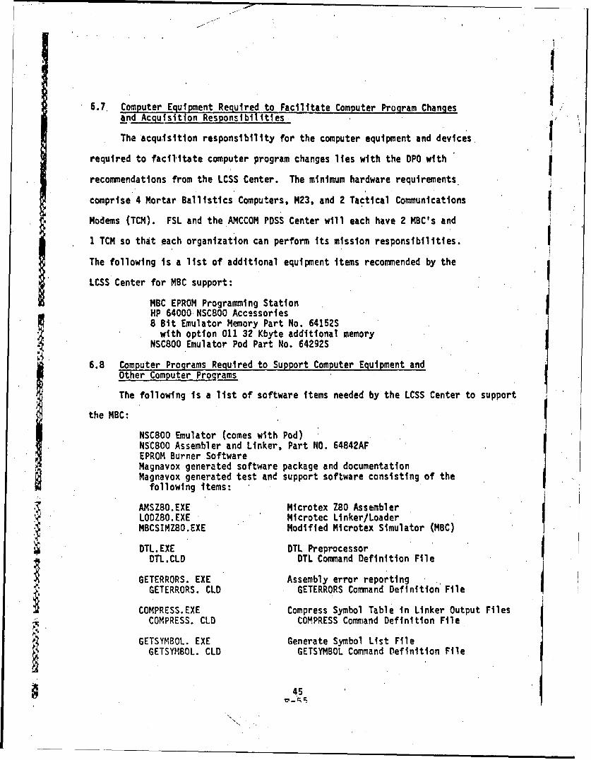
6.7 Computer Equipment 45Required to FacilitateComputer Program Changesand Acquisiton Respon-sibIlities
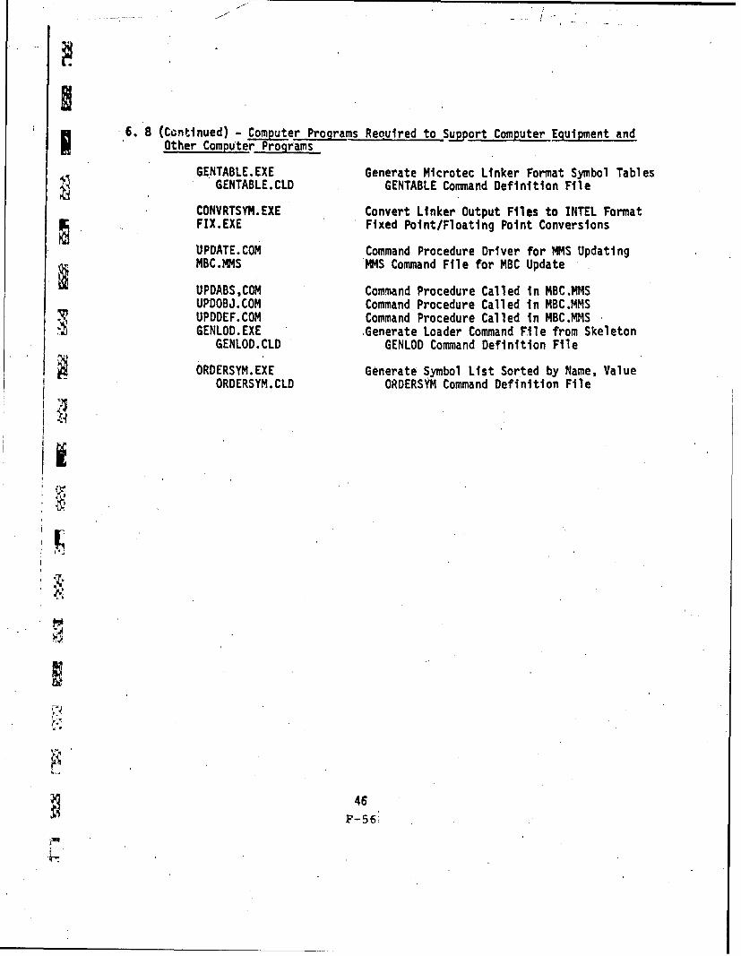
6.8 Computer Programs Required 45to Support Computer Equip-zente and Other Computer..-P r ~amsg .
6.9 Verification and Validation 47of Computer Programs
6.10 Plans to Establish and 47Operate Necessary SupportFacilities
6.11 Provisions for the Transfer 47of Program ManagementResponsibility
6.12 Provisions for System/ 47Equipment Deployment I
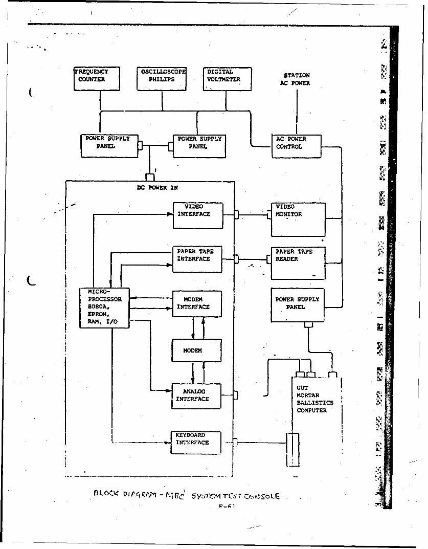
APPENDIX A MBC System Test Console A - 1-4
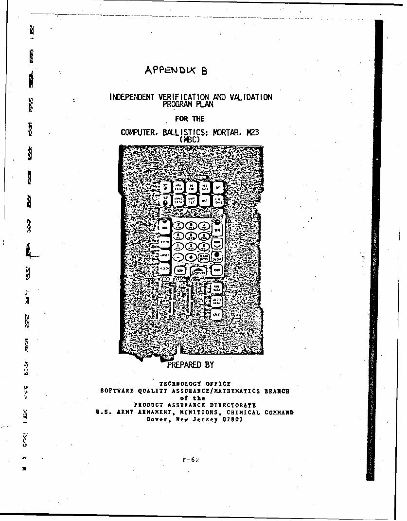
APPENDIX 9 Independent Verification and Validation Program Plan B 1-9 (B i-MY)
A 'PEDIX C Glossary - List of Key Terms and Acronyms C 1-7
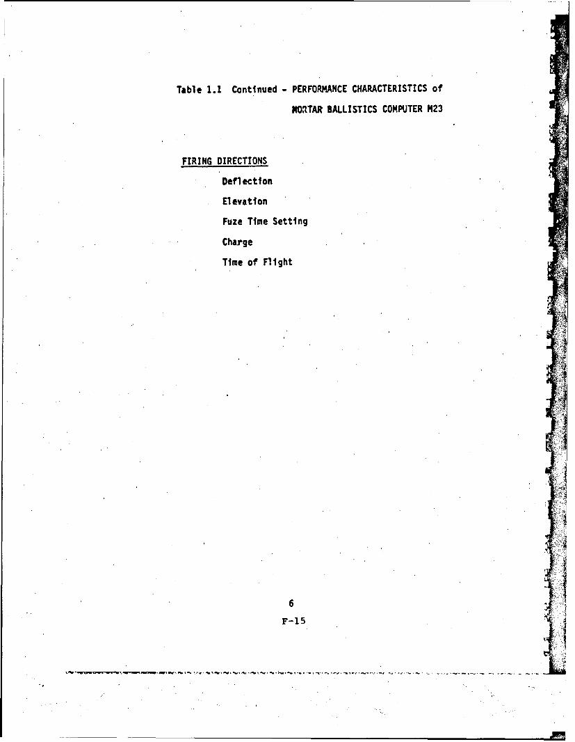
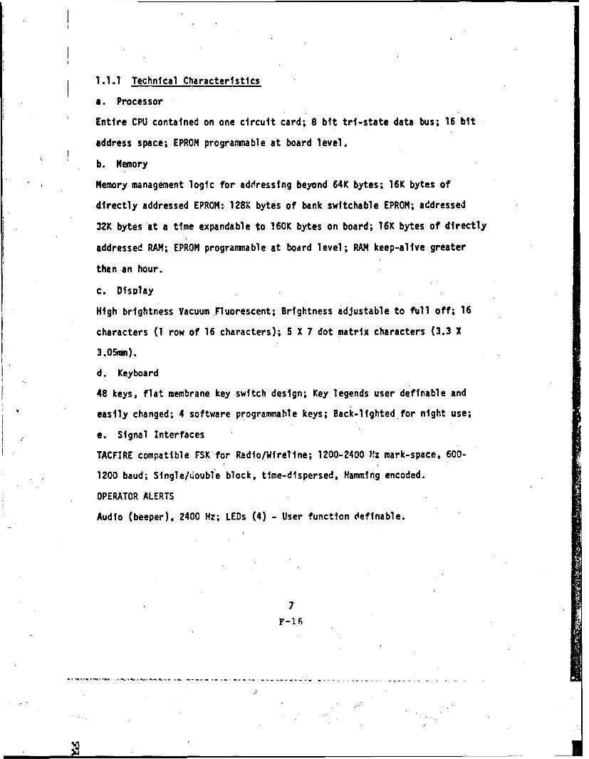
Audio (beeper), 2400 Hz; LEDs (4) - User function cefinable.
7
F-16
-------------------
4
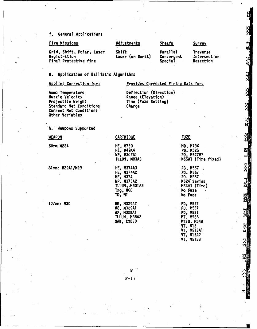
f. General Applications
Fire Missions Adjustments Sheafs Survey
Grid, Shift, Polar, Laser Shift Parallel TraverseRegistration Laser (on Burst) Convergent IntersectionFinal Protective fire Special Resection
6. Application of Ballistic Algorithms
Applies Correction for: Provides Corrected Firing Data for:
Ammo Temperature Deflection (Direction)Muzzle Velocity Range (Elevation)Projectile Weight Time (Fuze Setting)Standard Met Conditions ChargeCurrent Met ConditionsOther Variables
Integration testing will proceed in two levels. Software module inte-
gration testing will be started prior to full hardware availability, using
the NBC Software Support Center. Although this testing will be informal,
it will be performed by experienced software personnel under the direction
of the software engineer. The next level of, testing will be according to
a software test procedure based on updated software specifications. This
procedure will be designed to thoroughly exercise all functions and modules
of the Software System. Problems uncovered at this level will be fed back
into the development cycle and then re-evaluated by a complete rerun of the
acceptance test. These tests will initially be conducted at the Software
Support Center and finally on the target NBC hardware as it becomes avail-
able. All testing will be performed by software engineering personnel.
2.4.3 Software Development Facility
The basic approach for NBC program development is to link a program
development facility with the target hardware to a high level support
software on a host computer. The host computer is used for program compila-
tion, editing, simulation, and storage for source code DTL (Display Terminal
Language) preprocessing, and object code downloading to the development
facility. At the development facility, the actual NBC hardware is emulated;
thus program testing, debugging, and EPROM generation can be accomplished.
The Host Computer is connected to the Support Center through dedicated
communications ports. This configuration provides simultaneous access to the
Host facilities for all phases of the design effort. The M' Program Support
Center provides a centralized facility for the evolvement, preparation, ver-
fication, updating, programming of EPROMS and programming and program update for
20
- - F-30
I .. ..*.- -. .-... - '
the reprogramming of MBC units. It also has the capability of providing
programmed format or freetext radio or wire communlications with an MBC.
The Program Support Center may be interfaced to the host computer
directly through an RS232 interface or through other intermediate devices,
i.e., dual-in-modems or Magnetic Tape Cartridge reader/recorder. If the
host computer is not continually available, an intermediate download media
can be used. The intermediate device stores assembler output for later
programmer usage. Both batch job and interactive Jobs will be run on the
Host. Source C..e will be submitted to the Cross Assembler to obtain
exe-'utable code which can then be interactively exercisP4 on the simulator
from the work station terminal and downloaded for execution on the Support
System.
All MBC software support documentation of TOP 11785850 will be updated
to reflect the updated configuration. The support documentation to be
maintained and utilized for program development is as follows:
a. Program Support Center Documentation (Attachment 5 of M23 RFQ),
b. Display Terminal Language User Manual (Attachment 6 of M23 RFQ),
c. Software Programs Listings (Attachment 10 of M23 RFQ),
d. Software Program Source Listing (Attachment 14 of M23 RFQ),
e. Installation instructions for hosted support software,
f. All commercial equipment manuals, printer, terminal, PROM'burner, and
g. Assembler and Simulator manuals.
Production status programs are protected from modification and secured
in a software vault from which copies can be retrieved when required.
21F-31
2.5 Risk Assessment
The software risks during this phase of the MBC life cycle are relatively
low due to the following facts: a) The starting point Is a working program,
b) the processor uses a standard well supported language, c) the hardware
configuration is functionally not complex and d) very little concurrent
processing is required.
The areas of potential risks are listed below. It is to be noted that
these areas are not considered to be high risk items.
a. Meeting schedules and milestones;
b. Timely integration of software and hardware functions;
c. Memory sizing and management;
d. Human interface factors.
The potential risk areas will be minimized during development by frequent
U status reviews and close coordination between the contractor and Government
technical personnel, and the contractor's of allocating additional
support as may be necessary to resolve problem situations that may arise.
2.6 Use of Existing Systems, Equipment and Concepts
The software facilities, systems. equipment, concepts, etc., used for
this effort utilizes high payoff lew risk technology, and are considered
normal engineering facilities. The techniques are common to those used
when maintaining a modular designed program. The approach involves first
analyzing the logic and structure of the module to be changed and then
integrating in the required changes consistent with the original design
characteristicts. The NBC development effort is based upon tested systems
and technology used by the contractor in the DM0 programs.
".4
22
F-32
4 /
• I2.7 System Capacity to Provide for Growth
The NBC is presently configured so that approximately 75 percent of
the total memory capacity will be available for growth to accommodate addi-
tional shell types, ammunition types, and possibly new mortar calibers.
The memory circuit board is sized and wired to accommodate two additional
EPROM modules, for 32K bytes expansion. Provisions have been considered
for the technical interface requirements for implementaticn of the Fire Support
Team (FIST) DND in future production of MBC units.
2.8 Computer Program Development Cost
The projected program development cost for the Pre-Production Engineer-
ing (PPE) phase of the NBC life cycl, is $273,000.00 (in-house and out-house).
23
F-33
3.0 ACQUISITION MANASEMENT
3.1 Technical and Managerial Expertise for the Acquisition
Management of Computer Equipment and Programs
The DPO, XM23 has primary responsibility for the acquisition of computer
resources, including computer equipment and programs, as related to operational,
maintenance, utility support, factory inspection, and simulation software.
To assist the' DPO in computer resource acquisition management, several key
areas of technical and'managerial expertise have'been identified as follows:
a. Fire Control and Small Caliber Wedpon Systems Laboratory (7--), wll
provide technical expertise in the areas of MBC system engineering to include
functional computer hardware and scftware requirements and ATE.
b. Product Assurance Directorate (PAD) AMCCOM, will provide independe-t
AMCCOM verification and validation of the NBC incl-'ding computer resources
prior to release of the MBC to TECOM for Initial Production Test.
c. The AJCCOM PDSS center in conjunction with the AMCCOM ATE/PDSS/Th, DE
Control Offize will provide policy and guidance for computer resources.
The DPO, XM23 manages the overall computer resources acquisition effort.
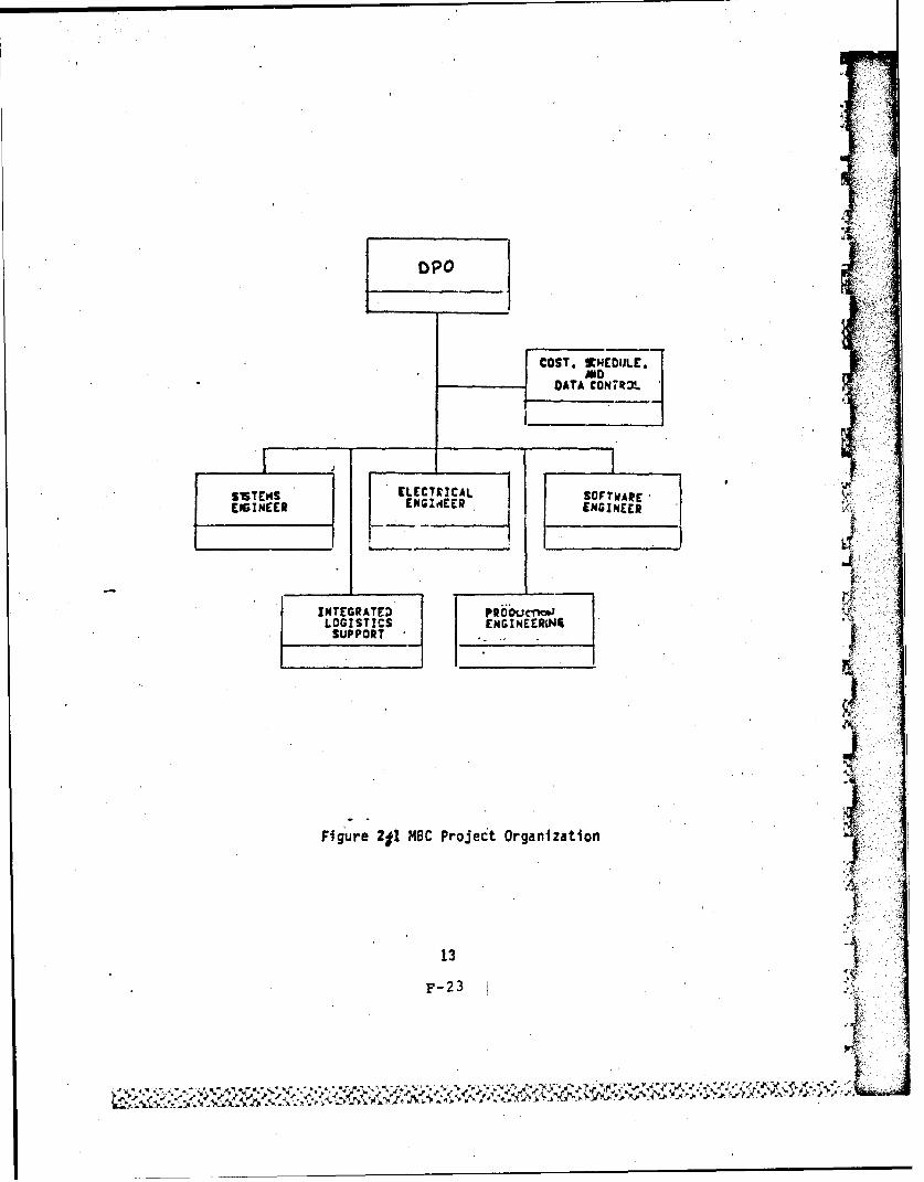
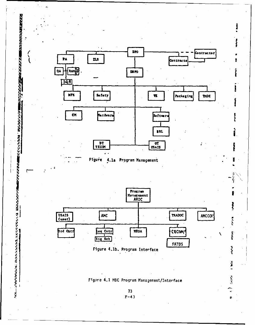
lhe computer resources support effort is portrayed by organitation In Figure 2.1, and
Figure 4.1. Technical expertise in digital communication interface (FIST OMD) Is
being provided by Pt1-FATDS.
3.2 Operational and Support Concepts
The concept of computer resources support for the NBC is based on a
) life cycle approach with the early involvement of all key participants.
": 24F-34
A formal Compu ter Resources Working Group (CRWG) has been re-estab-
lished to aid In the formulation of an overall computer resources support
plan, updeting of the CRMF, initiating tasks, assigning responsibilities
and providing the MBC Project office with support as needed.
Meetings will be scheduled to identify problems, make assignments of
action items, monitor progress with relation to assigned task completion
dates and milestones, and assess delivery of related data items with
respect to con ract schedules. Minutes of each meeting will be prepared for
distribution to attendees and key personnel associated with the program.
Thus, a written record of action items and progress will be available and
potential problem areas identified early. Frequency of the meetings will
be determined by the progress of the overall program.
3.3 System Engineering Approach
The TDP 11785850 will form the Product Baseline for system requirements
definition of the NBC computer resources. During development all changes to
the Product Baseline will be via Engineering Change Proposal (ECP) actions
in accordance with MIL-STD-480A. All ECP's will be incorporated into the
TDP by the contractor prior to production. This will allow a clean TDP to
be available for subsequent procurements-.
3.4 Standardization and Conmmonality
Standard computer resources will be used tG the fullest extent. Standard
Army ATE, e.g., simplified test equipment (STE) and AN/USM-410 (EQUATE) will
be utilized for maintenance support.
25
F-3 5 ,
3.5 Computer Program Data Rights
The Government shall have unlimited data rights to all MBC support
software as well as operational software. The MBC rights include the
right to use. modify, combine, reproduce and distribute all computer
programs and associated documentation.
3.6 A Master Schedule of 4 Major Milestones, Key Events, and Critical Actions
The master schedule for the overall NBC program is shown in Figure 3.1.
3.7 Identification of Required Interfaces Between the Computer Resourcesofthe-Tstem and Other Systems
3.7.1 The MBC/DMD interface allows for the automated exchange of data
between the MBC at the Fire Direction Center and the DMD located at Forward
observer locations. Total implementation of the MBC/DMD Interoperability
Program Technical Interface Requirements requires:
a. Explicit statement of system interoperability requirements at system
specification level.
b. Standardization or compatible usage of data elements, codes, terms,
formatting, and communication protocols, communication means, and data
message exchange across the system-to-system interface.
c. Availability of system interface documentation for planning, con-
ducting, and analyzing system interface tests, to include configuration
management.
26
F-36
v1
4
= 4.J
- i"
onk~
0-°GA t. ,- -
€ ,4 -l, 1. ,G O
OSO
4.1=
.
nn I. &M
- 4.1
3W, !
ac . 0
16- .. * a ,.
7 44,
U--Vt~~w a .. L~-~
c I*
4
.3A ua c. C3t
44. -jI
= IIn
67
.33
3.8 Retirements for Acquisiti(n and Support of Documentation
3.8.1 The following data shall form the product baseline for system software
requirements of the MBC computer resources:
Computer Program Development Specification, - Part I (BS)
Computer Program Configuration Item (CPCI) Test Plans/Procedures
Computer Program Product Specifications (C5) - Part II (C5).
3.8.2 The computer programs developed for the MBC are identified and
grouped into one CPCI. The structuring of the specification for the CPCI shall
be in accordance with MIL-STD-483/490.
3.8.3 Subsequent to the establishment of the CPCI Product Baseline at type
classification, all changes will be made by ECP action.
3.9 Facilities to Support Testing of Computer Programs
3.9.1 The prime contractor's plant shall be used as the Software Support
Facility (SSF) to support development test and evaluation of the MBC
deliverable computer programs.
3.9.2 The AMCCOM PDSS Center at Dover, NJ will be the Software Support
Facility (SSFj during the post deployment phase to perform maintenance and
modification of operational computer programs and associated documentation.
ARDC, FSL will provide software support for ATE. The contractor's plant shall
continue as the SSF during post development until such time as the
Government acquires the computer programs and associated documentation.
28
F-38
6--e
RC 01)r
c 1
ARC A
2P"
IJv
.r. r- fioessjAj o~MBC. S.StuAre. &o.-A 4 .3
29F-39
3.10 Configuration Management Concepts
The contractor is using a formal Configuration Management Program (CMP) to
assure traceability of changes. He will configuration manage the MBC, and
support systems until the Government assumes a formal configuration manage-
ment role after FAT. Subsequent to FAT ARDC will hold and maintain
the updated Technical Data Package (TDP); processing of software changes
from initiation to fielding shall be as shown in figure 3.2.
3.10.1 Processin of Software Changes from Initiation to Fielding
Element Activity
1 AMCCOM (R) reviews ECP/SCP/PIP requests andforwards validdted requests to ARDC for action
2 ARDC technical personnel, representing FSL, PAD-14 the PDSS Center:
o Develop the software (coding specifications, etc.)to update the MBC.
o Prepare a preliminary ECP/SCP.
o tevelop and test new updated circuit boards.
o Forward updated circuit boards to TECOM forconfirmatory test.
o Review test results and make appropriatechanges as may be required.
o Prepare final ECP/SCP, to include rLSconsiderations, and submit to ARDC-CCB.
o Update TSP's as may be reouired.
3 BRL acting on the ARDC request develops theFire Control Inputs (FCI) and test problems asmay be required for any new weapon/ammunitioncombination.
4 TECOM, acting on in ARDC request prepares tPstplans, conducts tests and prepares the testreport for submission to ARDC-CCB.
30
F-40
3.10.1 (continued) Processing of Software Changes from Initiation to Fielding
Element Activity
5 ARDC-CCP reviews the final ECP/SCPand forwards its recommendation tothe AMCCOM (R)-CCB.
6 'CCOM (R)-CCB approves the ARDC-CrBrecommendation, authorizes the changesand forwards, the arproved SCP to thePDSS Center for implementation.
7 Responsible PDSS Center personnel:
o Update software documentation andrevise the product baseline.
o Prepare the master bit pattern (forthe MBC EPROR's) and forward to theresponsible DEPOT.
o Verify the initial production boardswith TECOM.
o Approve production release of thecircuit boardp by the DEPOT.
o Store the revised production baselinein the TSD files.
8. PAD is assigned the responsibility for theIndependent Verification and Validation(IV&V) Program Plan. For IV&V tasksduring post deployment see Appendix B..Table 3.3.
9 The DEPOT is assigned the resronsibilityfor the updating, repair and distribution of
'revised circuit boards.
10 The fielding process Is the assignedresponsibility of AMCCOM (R).
3.11 Criteria for the Transfer of Program Management Responsibility
The MBC program management responsibility will be transferred from OPO,X1423 to AMCCOM (R) 120 days after Initial Operational Capability (IOC).
31i i ,F- 411
4.0 DEVELOPMENT MANAGEMENT
4. 1 Organizition, Respolsibilities, and Structure of Group(s) that will bee n , Produang, and Testing All Computer Programs
The organization structure which will be managing the design, production
and test of the MSC is indicated in Figure 4.1. The DPO, XM23 has the overall
responsibility to ensure that the MBC meets the Army's requirements. He is
assisted in this effort by the contractor and AMCCOM. Integrated Logistics
Support/Logistics Support Analysis management activities are within AMCCOM for
coordiration of logistics with computer resources activities. The prime
-contractor, is responsible for the design, development and testing (contractor)
of the NBC and its associated ILS package. The AMCCOM segments are involved as
follows: FSL is responsible to assist the DPO in the technical evaluation of the
* contractor design/development implementation, testing and documentation; the
AMCCOM PDSS Center will ensure software compliance with policies, standards and
procedures for Battlefield Automated Systems (BAS), and interoperability-related
~software pertaining to the Army Command and Control System for non-ATE software;
FSL will ensure BAS compliance for ATE software; the Product Assurance
Directorata is the AMCCOM independent evaluator for verification and valida-
tion of the MBC and its maintenance support equipment, including computer
resources. AMCCOM will provide logistics support in the area of ILS planning
and implementation as well as the conduct of Logistic Support Analysis (LSA).
TECOM is respcnsible for conduct of the Initial Production Test (IPT). USAISj
represents the user and will coordinate the Forece Development Testing and
Experimentation (FDTE)'. The DPO in conjunction with the PM-FATDS has
established specific quantitative design requirements for communications,
information exchange procedures, and software.
32F-42
a1raQA
Figure 4 .1a, Program Management
, '
ProarmManagement
ARDC
I i OCI o
Fgure 4.1B Program Manageent/I.e
F-43
4.2 DEVELOPMENT MANAGEMFNT AND TECHNICAL CONTROLS
4.2.1 Design reviews, tests and audits will be in accordance with the
contract schedule. CRWG teams will monitor these actions and will advise
the DPO accordingly.
4.2.2 The B5 Computer Program Development Specification for the MBC Computer
Program Configuration Item (CPCI) was updated by the contractor.
The CPCI is allocated to functions and tasks to be performed by individual
computer subprograms which are identified and described in the C5 Computer
Program Product Specification.
4.2.3 The updated C5 specification were submitted to DPO, XM23 for approval
at the conclusion of the Critical Design Review (CDR). The DPO will
establish theupdated Product Baseline at the conclusion of the Formal Qualification
Test (FQT). The objectives of the FQT will be to verify that the actual
performance of the CPCI complies with its development specification, and to
identify test reports and data that document the results of thp program
qualification tests.
34
F-44
4.3 Methodology for Ensuring Satisfactory Design and Testing, IncludingQuality Control
1. Testing shall be in accordance with the Coordinated Test Program
Management of Section 5 of this CRMP.
2. AMCCOM Product Assurance will participate in the design, develop-
ment, testing, configuration management, and maintenance of the computer
resources through the following functions:
a. Perform continuous assessments of the contractor's Software
Quality Assurance (SQA) Program to ensure that reviews, audits, verifica-
tion, testing, and procedural and product aspects of system development are
* performed in accordance with the guidelines of MIL-STD-52779A and contract
requirements.
b. Participate In all formal review and walk-throughs to ensure
their completeness and accuracy.
c. Review and take part in the approval of all contractor sub-
mitted software documentation.
d. Maintain appropriate records of all assessments and tests
in support of the following activities:
* (1) Program'validation
(2) Post deployment baseline change evaluation
(3) Post deployment test management
(4) Technical Data base
e. Advise the DPO, XM23 on the performance, quality and supporta-
bility of the software program.
35
pF- 45
f. Provide input on compute. resources to required Government
Product Assurance documentation.
g. Eval.aate and participate In the approval of the final CPCI
" test plans/proc&;res and monitor the actual acceptance test of the
software program to ensure all requirements and documentation are verified.
4.4 Development Schedule for each CPCI and Proposed Milestone ReviewX, Points
The development schedule for the MBC CPCI and milestone review points
appear in Figure 3-1. ATE mileetLones will be determined prior to MR (Material
Release).
4.5 The Procedure for Monitoring and Reporting the Status of Computer: Program Development
The status of computer program development shall be monitored via
technical reviews, tests, and audits that are held to cnntrol CPCI.
4.6 The Resources Required to Support Development and Test of ComputerPrograms
dThese resources are identified in paragraph 2.2.4.7 The General Procedures for Reporting, Monitorin, and Resolving
Computer Program Errors and Deficiencies Di ring Development Test
The general procedures are outlined in the CPCI Test Plans/Proceduresand the contractor's Software Product Assurance Manual.
4.8 THE Method and Procedures for Collecting Data, Analyzing, MonitoringV. and Reporting on the Timing of Time Critical Computer Programs
or The DPO will provide and maintain timing and sizing budget estimates
for the CPCI as specified in the B-5 specification.
16
F-46
4.9 The Management of Previous, Current. and Proposed Revisions of Computer
Pr.._ogram asters ata Base, and Associated Documentation
During PPE the contractor shall manage all versions of computer program
masters and data bases and documentation. After deployment the AMCCOM POSS
Center and FSL shall assure this responsibility in accordance with the HQDA
P0SS concept plan approved May 1981.
4.10 Guideline and Checkpoints for Ensuring 'Future Computer Program Growth-
Modularity, and Ease of Modification
During'periodic reviews computer program growth, modularity, and
ease of modification will be examined.
4.11 Documentation-Approach
For the CPCI the following documentation will be prepared: a B5
specification, CS specification, program listing and firmware documentation.
4.12 Training Requirements and Associated Equipment
The contractor will develop and conduct operator and msintenance
courses for Instructor/Key Personnel (IKP). The IKP courses will cover
tasks associated with the new items to be introduced. The difficulty
level of the instruction will not exceed the mental and physical require-
ments outlined in AR 611-201 for each MOS. The date of course delivery,
the number of courses, the course lengths, the number of students shall
be consistent with the IKP requirements. The instruction will, be con-
sistent with and will as a minimum, train the critical tasks identified
by the ongoing tSAR. The instruction will be supported.by reproducible
draft TM's and will be a combination of classroom and practical training.
All operator courses will be conducted at the USAIS, Fort Benning, GA;
the maintenance courses will be conducted at AMCCOM (R), Rock Island, IL.
37
F-47
4.13 Software Engineering Practices
The DPO has the responsibility for Identifying the software engineering
practices that will result in the design, development, test, and delivery of
software that is acceptable and maintainable. The PDSS Center will provide
the expertise as requested by the DPO to assure this responsibility.
The design approach will stress structure, independence, of components,
modularity, and clarity of interconnections. Documentation shall stress
traceability, formal standards, clarity of descriptions, and easily readable
listings. Testing will stress formal demonstration of mission requirements
and use formal error data collection methods.
The contractor will be guided by the following practices:
a. Structured Design
b. Top Down Development
c. Formal Standards and Guidelines
d. Data Item Index
e. Program Design Language
f. Structured Programming
g. MBC Development Folder
h. Structured Walkthrough
I. Programming Support Library
J. Formal Error Data Collection
38
F-48
4.14 Security Control and Requirements
Classified data within MBC Computer Programs will be treated with the
same standard safeguards which are required for all classified information.
4.15 Schedule and Description of the Technical Milestones and Attainment
Criteria
MILESTONE SCHEDULE or ACTUAL !ATE
System Specification Nov 81
Contractor Devel-ped Specification Jan 84
Computer Program DevelopmentSpecification (B5) May 84
Computer Program ProductSpecification (C5) May 84
Computer Program Configuration
Item Test Plan/Procedures Jun 84
Critical Design Review Sep 83
Formal Qualification Test Oct 84
Physical Configuration Audit May PS
MBC Support Software Oct 85
EPROM Programming Station Oct 85
MBC Software Development System Oct 85
ATE Test Program Sets Sep 86
39
F- 4 9
5.0 COORDINATED TEST PROGRAM Mt.NAGEMENT
5.1 Responsibility and Interrelationships
The Test Integration Working Group (TIWG) which has been established for
the Mortar Ballistics Computer will ensure that the MBC computer resources
are properly tested and evdluated. The responsibilities of the Commands for
this effort are described in Paragraph 4.1 of this CRMP.
5.2 Organization/Activities Responsible for'Verification and Validation
5.2.1. The Product Assurance Directorate is the ANCCOMindependent evaluator
for verification and validation of h_ mRC and Its maintenance support
equipment, including computer resources.
The Product Assurance Directorate will participate in the review and approval
of contractor CPCI Test Plans/Procedures and the Product Assurance Test,
Demonstration and Evaluation Plan. These procedures will be utilized for
software validation and verification. Validation and verification results
will be reported by the contractor in the Quality Inspection Test,
Demonstration And Evaluation Report.
5.3 Development/Acquisition Schedule for Special Test Tools
MBC mainteaiance will require the use of Automatic Test Equipment. This
will necessitate the development of Test Program Sets (TPS's) for the MBC
and Circuit Card Assemblies. These will be initially developed by TOAD under
supervision of FSL for the specific ATE requirements of the MBC maintenance
concept. The ATE milestone is scheduled for 4QFY86.
4n
m~iF 5 0
5.4 Test Requirements Analysis Methodolog,
Analysis methodology is described in the CPCI Test Plans/Procedures.
It identifies those tools, techniques, and methodologies In the software
development which support QA objectives.
5.5 Methodology and Schedules of Benchmark Test Cases for Various Levels
of Software Testing
Testing activites shall continue throughout the entire PPE phase. Two-
distinct levels of testing are defined as part of this activity: Unit Test-
Ing and Software Integration Testing. As modifications are made to the
program as the result of change activity, error correction or required re-
design, and as these modifications are integrated into the system, it shall
be necessary to repeat tests at either level to verify the operation of the
modified program system. Tests shall verify that specific inputs produce
the proper responses.
5.5.1 Unit Testing
This activity will proceed as an extension of the top-down
approach to thesoftware design and implementation. Testing will consist
of exercising programs and routines in programs individually by using a
range of known expected inputs and comparing the resulting programs outputs
with expected outputs. Such testing shall continue until the results
indicate that the computer program unit reflects the program design and is
"error free".
5.5.2 Software lntegration Testing
Program units will be incrementally integrated and tested to exercise
functional compatibility. This testing will emphasize the interaction
41F-51
between related performance characteristics of the MBC to verify program
interfaces and to ensure that the program operates in accordance with the
Computer Program Development Specification (BS). Simulated systems inputs
in varying degrees of complexity will test and verify the integrity of the software.
All software will be integrated and tested on MBC hardware prior to First
Article Test (FAT).
5.6 Software Monitoring Design Plan
The contractor will use his own policies, procedures and documentation
to monitor software and ensure that computer software delivered to the
Government fulfills all contractual requirements.
5.7 Procedures for Reporting and Resolving Computer Program Errorsand Deficiencies During Testing
The procedures for reporting and resolving computer program-errors during
contractor PPE testing include the use of letter reports and recommend corrective
resolutions in the form of preliminary engineering change proposals (PECPs).
Prior to FAT the contractor will act on Government approved PECPs to correct the
errors and shortcomings uncovered during PPE. After implementation the contractor
will document and validate all mandatory changes. The software changes will be
implemented by the development of new memory coding by reprogramming the
existing eraseable programmable read only memory (EPROM) chips.
5.8 Schedule for Test Plans and Testing
The test plans and test schedules are contained in the Coordinated Test
Program fCTP) dated 15 July 1984.
42
F-52
6.0 POST DEPLOYMENT SUPPORT
6.1 Responsibility
AMCCOM CR) is responsible for post deployment management of the HBC program.
The AMCCOM PDSS Center, FSL, and PAD have responsibility for providing com-
puter-resource support to the deployed MBC and to Government users.
6.1.i The PDSS Center Computer Resource Support will include ECP evaluation,
software management, maintenance (software change implementation and control),
test and other related functions necessary to ensure the operational
capabilities of the fielded MBC. The computer resource management procedures
will be consistent with DARCOMR 70-16 and with this CRMP.
6.1.2 FSL is responsible for system engineering, to include ECP evaluations,
system level change integration, and system level testing. FSL is also
responsible for ATE and TPS's which include maintenance, test and other related functions.
6.1.3 The AMCCOM Product Assurance Directorate is responsible for all
software QA functions to include generating all test procedures, monitoring
tests performed by PDSS and assessing test results for final program
validation and verification.
* 6.1.4. The ATE/PDSS/TMDE Control Office, AMSMC-MA-ATE will provide
user field software support via strategically placed Field Service Requirements
(FSR). This office will also serve as the AMCCOM Nationat Maintenance Point ('NP)
liaison to the AMCCOM PDSS Center on matters concerning software maintenance of
Battlefield Automated Systems (BAS).
6.2 Configuration Management
Configuration Management is the responsibility of AMCCOM for baseline
and change control of the MBC. The ACCOM level II CCB, including the PDSS
Center, FSL, and PAD, will handle AMCCOM actions directed by the AMCCOM
level I CCB. Overall configuration management will be conducted in accor-
dance with AR 70-37 with change control actions (ECP's, VECP's and RFD/W's)
* prepared in accordance with DOD-STD-480A.
43
* F-53
S 6.3 Responsibilities for Composite System Integrity
After the initial production phase of the MBC program is completed, the
P responsibility for software support will be transferred to the LCSS Center.
S The LCSS Center will maintain the composite system integrity including:
a. Computer memory storage utilization
b. Computer program time constraints and priorities
c. Computer program interface techniques
d. Computer program baseline integrity
e. Use of computer modules and peripherals
f. Software change engineering and implementation.
6.4 Documentation Required to Support Each-Type of Computer Program
Documentation requirements are identified in Section 3.8 and 6.8. The
repository for these documents will be the LCSS Center. These documents
will be utilized by the various AMCCOM elements, which will be involved
during the post deployment phase (e.g., FSL, PAD, TSD).
S 6.5 Responsibility for Funding
The Post-Deployment funding for the support of operational software
M will be the responsibility of AMCCOM. AMCCOM (R) will be responsible for
obtaining funds for the engineering and installation of changes/modifica-
" tions to software. AMCCOM (R) will also be responsible for obtaining funds
for the procurement of the hardware/software resulting from these changes.
6.6 Personnel Required for Computer Resources Support
The personnel required for supporting computer equipments and programs
will be supplied by tho LCSS Center, FSL and PAD. Each organization will
be tasked with identifying the core personnel.
44
P-54
6.7 Computer Equipment Required to Facilitate Computer Program Changesand Acqutsition Responsibilities!
The acquisition responsibility for the computer equipment and devices.
required to facilitate computer program changes lies with the DPO with
recommendations from the LCSS Center. The minimum hardware requirements
comprise 4 Mortar Ballistics Computers, M23, and 2 Tactical Communications
Modems (TCM). FSL and the ANCCOM PDSS Center will each have 2 MBC's and
1 TCM so that each organization can perform its mission responsibilities.
The following is a list of additional equipment items recommended by the
LCSS Center for MBC support:
MBC EPROM Programming StationHP 64000 NSC800 Accessories8 Bit Emulator Memory Part No. 64152S
with option 011 32 Kbyte additional memoryNSC800 Emulator Pod Part No. 64292S
6.8 Computer Programs Required to Support Computer Equipment andOther Computer Programs
The following is a list of software Items needed by the LCSS Center to support
the MBC:
NSC800 Emulator (comes with Pod)NSC800 Assembler and Linker, Part NO. 64842AFEPROM Burner SoftwareMagnavox generated software package and documentationMagnavox generated test and support software consisting of the
COMPRESS.EXE Compress Symbol Table in Linker Output FilesCOMPRESS. CLD COMPRESS Command Definition File
GETSYMBOL. EXE Generate Symbol List FileGETSYMBOL. CLD GETSYMBOL Command Definition File
45
p 6. 8 (Continued) -Computer Programs Reouired to Support Computer Equipment andOther Computer Programs
GENTABLE.EXE Generate Microtec Linker Format Symbol TablesGENTABLE.CLD GENTABLE Command Definition File
CONVRTSYM.EXE Convert Linker Output Files to INTEL FormatFIX.EXE Fixed Point/Floating Point Conversions
UPDATE.COM Command Procedure Driver for MS UpdatingMBC.MMS MS Command File for MBC Update
UPDABS,COM Command Procedure Called in MBC.MMSUPDOBJ.COM Command Procedure Called in MBC.MMSUPDDEF.COM Command Procedure Called in MBC.MMSGENLOD.EXE Generate Loader Command File from Skeleton
GENLOD.CLD GENLOD Command Definition File
ORDERSYM.EXE Generate Symbol List Sorted by Name, ValueORDERSYM.CLD ORDERSYM Command Definition File
46F-561
6.9 Verification and Validation of Computer Programs
The approval for Materiel Release of post deployment software
changes will be the responsibility of the Product Assurance Directorate.
of A.MCCOM.
6.10 Plans to Establish and Operate Necessary Support Facilities
The AMCCOM PDSS Center will establish the requirements for support
facilities. The plan for the PDSS suportability demonstration will be
formulated when the PDSS requirements for the MBC computer resource
items become clearly defined by the DPO, XM23.
6.11 Provisions for the Transfer of Program Management Responsibility
The MBC System is under management of DPO, XM23. All computer
resources files and technical data will be provided to the AMCCOM PSS
Center within 30 days after the PROD-VAL IPR.
6.12 Provisions for System/Equipment Deployment
The system shall be deployed in accordance with the Materiel Fielding
Plans after materiel release.
JL-.- 47
F-57.
2*
APPENDIX A
SYSTEM'TEST CONSOLE
FOR THE
MORTAR BALLISTICS COMPUTER, M23
A-1
jF- 58
Appendix A
1.0 INTRODUCTION
This section describes the System Test Console used to test theMortar Ballistics Computer, M23. The block diagram denotes the componentsof the test station and the interconnection of each.
2.0 HARDWARE
2.1 System Test Panel
The system test panel contains an 8080A microprocessor with two(2) kilobytes of RAM and eight (8) kilobytes of EPROM. The microprocessorcontrols the station operation via the resident software in EPROM and thecommand instructions it reads and executes from the paper tape. The panelcontains the hardware to transmit messages to and receive messages from theMBC through the modemn and analog interface circuitry and can also make any
* keyboard entries using the keyboard interface. The video Interface informsthe operator of test status and results and prompts for any manual-operationsrequired.
2.2 Power Supply Panels
The power supply panels supply the 'Svdc and +12vdc to the system testpanel and an adjustable DC power source required by the MBC.
2.3 AC Power Control Panel
The AC power control panel distributes the AC power to the DC powerpanels and the commercial equipment as required. It also provides thecircuit breaker protection for the station.
2.4 Commercial Equipment
The commercial equipment utilized in this station Includes:
A. Video Monitor Conrac Model SNA14/CB. Paper Tape Reader Addmaster Model 650-2C. Oscilloscope Philips Model PM3217D. Digital Voltmeter Fluke Model 8040AE. Frequency Counter GenRad Model 11918
3.0 SOFTWARE
3.1 System Test Panel Software
The software contained in the eight (8) kilobytes of EPROM in the systemtest panel is an interpreter for the command instructions on the paper tape.This software reads the command instructions from the paper tape and executesthem as they are read. The video modem, analog, relay, and keyboard interfacesare all controlled ,by this software. The command instructions are furtherdiscussed below in the paper tape software section.,
A-2
F-5
Appendix A
3.2 Paper Tape Software
The command instructions contained on the paper tape are executedsequentially by the system test parel as they are read. Each commandbegins with an asterisk (*) wl,,ch is followed by a single character whichdetermines the type of command to be executed. The characters whichfollow are parameters of the command type and are dependent on the commandtype. The command type characters and their functiuns are briefly describedbelow.
COMMAND TYPFCHARACTER DESCRIPTION
C Compose massage on UUT keyboard.
D Display message on video monitor.
E Introduce single bit error into everycharacter transmitted to UUT.
H Halt test station.
I Induce error in any character or bitposition in transmitted messaae.
SK Switches relays in test panel tocorrect audio signal and level.
N Load test number into station buffers.
R Loads message to be received into stationthen activates key to transmit messageand then compares received message.
S Sets station status for correct parameters.
T Loads message to be transmitted into station*and time disperse message and parity buffers.
V U.S. ARMY ARMAMENT, MUNITIONS, CHEMICAL COMMANDDover, Nev Jersey 07801
F-62
AB STRACT
This Independent Verifica tion and Validation (IV&V) Program Plan containsinformation on the planning, coordination, and specific V&V tasks requiredto conduct an IV&V program on the Computer. Ballistics: Mortar. H23(MBC).This program vill provide the DPO NBC and AMCCOM with an independent andcontinuous assessmen' t of the NBC computer resources during production andpost deployment phases of the NBC life-cycle.
4.3 USE OF THE DEVELOPER'S RESOURCES .............................. 9
-ii
F-64
LIST OF TABLES
Table Title Page
3.1 MILESTONE III PROGRAM REVILW AND PRODUCTION CONTRACT
3.2 XT&V TASKS DURING PRODUCTION................... o........ 6
3.3 IV&V TASKS DURING POST DEPLOYMENT ................ 7
3.4 IV&V TASKS TO IMPROVE NBC QUALITY, RELIABILITY AND
SU PO T BI IT . o .. . .. .. ...* o .. . . o .iii. .
F-65
SECTION I
GENERAL
1.1 INTRODUCTION
*This section provides an overview of the purpose, scope, andauthority for the preparation of this Independent Verification andValidstion (IV&V) Plan for the Computer, Ballistics: Mortar, M23 (MBC).
1.1.1 PURPOSE
The purpose of this IV&V Plan is to identify those specific V&Vtasks that must be performed adequately to provide the necessary data,analyses, and testing to assure a thorough IV&V for the MBC program duringthe production and post deployment phases of its life-cycle.
1.1.2 SCOPE
This plan applies to the IV&V effort during the production andpost deployment phases of the MBC life- cycle. Specific V&V tasks vhich are
Sperformed during these phases to accomplish overall IV&V objectives areidentified in Section III.
k _1.1.3 AUTRORITY
This plan yas prepared under the auspices of the DevelopmentSProject Office (DPO) MBC for inclusion in the Computer Resources Management
Plan (CRMP) for the MBC and in accordance with AMC R 70-16 and the DraftAMC Product Assurance & Test (PA&T) policy on Independent Verification &
SValidation.
1.1.4 DEFINITION
Independent Verification and Validation- is a major activity ofthe total quality program (both software and hardva.-e) to independentlyassess/confirm compliance vith requirements.
C Independent - an organization that is seperate from the development activityfrom a contractual and organizational standpoint.
Verification - is the evaluation process designed to ensure the consistancyand completeness of the software product at any given phase within the MBC.life-cycle.
Consistancy is concerned vith measuring the degree to which a givenphase (e.g., design) is in agreement vith the previous phase (e.g.,
.requirements) in the development and post deployment change cycles.
Completeness is a measure of the readiness to initiate the next phaseW. in the development and post deployment change cycles.
*F-66
Validation - is the integration, testing, and/or evaluation activities Icarried out at the system and subsystem level to evaluate the developedomputer program against the system specifications and the user'
- equirements.I
I
2I
F-67
SECTION 11
IVT PROGRAM APPROACH
2.1 PROGRAM OVERVIEW
The IV&V program viii provide an independent and continuous5assessment of the MBC computer resources through the production and post
post deployment phases. This effort viii ensure that all necessaryanalyses, evaluations, and tests are conducted efficievtly and effectivelyto preserve the pre-established levels of quality, reliability andmaintainability of the MBC software. This IV&V effort vill also includeassessments of the equipment necessary to support the production, factorytesting, and the post-deployment softvare change environment to assureits proper functioning. Additional IV&V tasks may be conducted to improvethe quality, reliability, and supportability of the MBC.
2.2 PROGRAM ADMINISTRATION
PAD has been assigred responsibility for the IV&V program in,, support of the DPO MBC and AMCCOM. PAD will utilize data generated from V&V
activities performed by all organizations in the accomplishment of theoverall IV&V program. Additional tasks to improve the quality, reliabilityand supportability of the MBC may be performed by an IV&V contractor or
PAD.
2.3 PROGRAM FUNDING ESTIMATION AND DISTRIBUTION
PAD as the responsible organization in support of the DPO MBC andAMCCOM vilI control all necessary funds to assure completion of the IV&V
program.
2.4 INTERFACES AND COORDINATION
* The DPO-MBC as the overall MBC program manager vill be the focalpoint of communication betveen the developer(s) and the IV&V effort. Alldata and documents required will be requested through the DPO and allreports and anclyses generated vill 'be' submitted to the DPO. This policywill maintain an orderly flov of information and reduce interference withthe developer(s).
All IV&V plans/activities as vith all MBC related actions aresubject to final approval of the DPO-MBC.
8-3
F-68
BICTION III
I&V TASK DEFINITION
3.1 IY&W PASE DEFINITIONS
3.1.1 NILESTONE III PIOGRAM REVIEW & PRODUCTION CONTRACT /
This phase of the IV&V program will be initiated after FirstArticle Testing (FAT) has been completed by Magnavox. The final productbaselines for the MtC software viii be established and the productionphase will be initiated '. Specific tasks to be accomplished during thisphase are identified in Table 3.1.
3.1.2 IV&V TASKS DURING PRODUCTION
Table 3.2 defines all the tasks which vill be executed during the
production phase of the MBC.
3.1.3 ILVV TASES DURING POST DEPLOYmenT .
The designated PDSS center for the MBC will be the AMCCOM LCSScenter located at ARDC Dever, NJ. The tasks which will be performed duringthe post-deployment phase of the MBC are identified in Table 3.3.
(-3.2 IV&V TASKS TO IMPROVE MBC QUALITY. RELIABILITY 6 SUPPORTABILITT
Table 3.4 identifies IV&V tasks which may be performed in orderto improve the quality, reliability and supportibility of the MBC. Thesetasks will establish a traceability data base btcween requirements anddesign documentation to the source listings. This will greatly improve thecurrent documentation of the MBC software program. Also static as well asdynamic analyses will be conducted to determine complexity, improve testcoverage and measure as well as improve the quality and reliability of theMBC software program.
I4
I
F- 69
'TABLI 3.1
! MILISTON III PROGRAM REVIEW & PRODUCTION CONTRACT
0 Assist in Functional & Physia1 Configuration Audits,
e Assess and evaluate all equipments necessary to support theproduction process (ATE etc.)
* Reviev Production Planning
o Assess Configuration Management for Production
e Assess Quality Assurance for Production
* Assist in Revieving/Preparing Technical Data Packsge
# Assess Computer Resource Needs for Production
* Assess Prodrtion Contract for Computer Related Items
* Assess Production Testing Plan & Procedures
o Assess Software Handling Procedures for Production
* Establish the pre-PDSS baseline for requirements specs,' test
procedures etc.
F 7
/ F- 70
/
/
TABLI 3.2
IV&V TASKS DURING PRODUCTION
* ZCP evaluation and trace maintenance
R Reviev for Compliance to Softvare Standards, Policies and
Procedures
" Assist in Establishing Audit Trail
" Assess Production Testing for Continuance of PerformanceBaseline
* Reviev QA and CM Procedures1 *Assist in Establishing System Assessment Pipeline forOperational/Fielded Systems
o Monitor Approval & Disposition of Formal Releases
o Continual assessment of all production test equipment
o Acceptance test analysis for softvare "bug" symptoms
I~p
e-6
F-71
TABLI 3.3
IV&V TASKS DURING POSE DEPLOYMENT
0 Conduct PDSS supportability demonstration
- Assess MBC development environment- Certify all support equipment- Evaluate CM procedures- Evaluate Softvare Engineerirg procedures
a Assess/Evaluate Software QA Plaa/rocedures for'PDSS
* Evaluate/Assess Failures in Oreration/Fielding
# Assess System Failures and Need for Change (ECP)
s Perform Revalidation
- Reverify that Requirements are Being Met- Use Tracking Data Base- Evaluate Impact of Change
% Redesign and Recode as Required
- Use Test Tools as Required- Assess Changes to Documentation- Update Configuration
e Revalidate Software
- Repeat Key Tests to Reaffirm Confidence in System Softvare- Review Baseline and Archive Data & Programs
* Maintain IV&V baseline and technical competence
B-7
F-72
TABLE 3.4
' ZI&V TASKS TO IMPROVE NBC QUALITY, RELIABILITY & SUPPORTIBILITY
9 Establish a Requirements Tracing Data Base between LR. and MBC
software development specifications
* Use Metrics to Assess Quality factors
* Trace softvare requirements into Design documentatien
* Run models and simulations
* Reviev code against Design documentation
* Trace code to design
* a Use static and dynamic analysis tools
* Establish a 'trace between test and requirements documents
* Develop independent test scenerios
* Perform a reliability assessment
F-73
JSCTIOW Ty
TOOLS AND IQUIPIXUT
4.1 TOOLS
The IV&V Program may procure NBC specialty tools o, modifyalready existing tools to accomplish many of the IV&V tasks. Xquipmentneeded to support the development/fabrication/testivg of the NBC viii beshared with the LCSS center.
4.2 XQUIPHINT
The IV&V program viii have access to a CP/M compatible Z80distributed processing TURBO D3S microcomputer system and a DigitalEquipment Corporation VAX 11/780 Computer system with VMS and UNIXoperating systems. Also, a Input-Output Requirements Language (IORL)developed by Teledyne-Brown Engineering will be loaded on the VAX andApollo work station. IORL will be used for all requirements tracifg whichwill establish a tracking data base system for the NBC.
Additional equipment for independent tests and/or evaluationassessments of the NBC may be purchased as required.
I 4.3 USE OP THE DEVELOPER'S RESOURCES
The possible use of a developer's tools and/or equipment Vill becoordinated through the DPO-MBC to assure no interference with thedevelopment process.
9-9
'I F-74
APPENDIX C
GLOSSARY
List of Key Terms and Acronyms
F-75
APPENDIX C
A
ACK Acknowl edged
AMC US Army Materiel Command
AMCCOM US Armament Munitions' and Chemical Command
ANSI American National Standard Instruction
AR Army Regulation
ARDC US Army Research and Development Command
ASCII American Standard Code for Information Interchange
ASL Authorized'Stockage List
ATE Automatic Test Equipment
B
BAS Battlefield Automated Systems
BAUD Measurement of data transmission rates expressedas "bits per second" or bps
BIT Build-In-Test
bit A unit of data in the binary-numbering system
BRL Ballistics Research Laboratory
byti A generic term to indicate a measureableportion of consecutive binary digitq
C
CCB Configuration Control Board
CDR Critical Design Review
CECOM US Army Communication and Electronics Command
FDTE Force Development Testing and Experimentation
F-3 F-7 7
APPENDIX C
F
FIST Flit, S upport Team
FO Fork-rd Observer
FQT Formal Qoialification Test
FR Fire Request
FSD Full-!cale Development
FSK Frequtncy-Shift Keying
FSL Fire Control and Small Caliber Weapon Systems'Directory
FSR Field Service Requirements
FUE First Unit Equipped
G
GFE Government Furnished Equipment.
H
HFE Human Factors Engineering
HOL High Order Programmuijig Language
1/0 Input/output
IKP Instructor/Key Personnel
115 Integrated Logistic Support
10C Initial Operational Capability
IORL Input-Output Requirements Language
IPR In-Process Review
IPT Initial Production Test
IV&V Independent Verification and Validation
C- 4F-78
APPENDIX C
K
K A symbol which is equivalent to the numeral 1024
Kilobyte Denotes 1,000 "bytes"
L
Language A defined set of characters used to form symbols, words,etc., and the rules for combining these into meaningfulcommunications
LED Light Emitting Diode
LSA Logistic Support Analysis
LSAR Logistitc Support Analysis Record
LWCMS Light Weight Company Mortar System
LCSS Life Cycle Software Support
LR Letter Requirement
N
MBC Mortar Ballistics Computer, M23
MFCC Mortar Fire Control Calculator
MODEM MOdulator DEmodulator Unit. A device that converts datafrom a form which is compatible with data.processing equipmentto a form that is compatible with transmission facilities,and vice-versa.
MOS Military Occupational Sepecialty
MR Materiel Release
MRSA US Army AMC Materiel Readiness Support Activity
N
NAK Not Acknowl edged
NET New Equipment Training
Ni Cad Nickel Cadmium
NMP National Maintenance Point
0
C-5F-79
APPENDIX C
P
PAD Product Assurance Directorate
PA&T Product Assurance & Test
PCA Physical Configuration Audit
PDSS Post Deployment Software Support
PE Production Engineering
PIP Product Improvement Proposal
PLL Prescribed Load List
PPE Pre-Production Engineering
PROD-VAL Production Validation
PROGRAM A set of instructions or steps that tells the computerexactly how to handle a complete problem, e.g. ballistics
QA Quality Assurance
R
RAM Random Access Memory,
RAM-D Reliability, Availability, and Maintainability-Durability
RFQ Request for Quotation
ROM Read Only Memory
S
SCP Software Change Proposal
SP Software Package - Various Computer programs or sets ofprograms used in a particular application such as amortar ballistics package
SQA Software Quality Assurance
C_
F-80
1
APPENDIX C
S
SSF Software Support Facility j5SP System Support Package
STE Simplified Test Equipment
T.TACFIRE, Tactical Fire Direction System
TC Type Classified jTCM Tactical Communicatlons Modem
TDP Technical Data Package
TECON US Army Test and Evaluation Command
TIWG Test Integration Working Group
TH Technical Manual
TMDE Test, Measurement, and Diagnostic Equipment N
TOAD Tobyhanna Army Depot
TPS Test Program Set
TRADOC US Army Training and Doctrine Command
TOD Technical Support Directorate
TSO Time Sharing Option
*U
UNIX An operating system for 16-bit computers
USAIS US Army Infantry School
UUT Unit Under Test
V
VE Value Engineering
W
WSMR White Sands Missile Range
C-7
' t F 81
* ANNEX G
SUPPORTING DATA
FOR
MATERIEL RELEASE
OF
Flo COMPUTER, BALLISTICS: MORTAR, M23
4,
G-1
U MATERIEL RELEASEIN SUPPORTING DATA TOR
Itin 1menclature: Computer. Ballistics; Mortar Set M23
~ 35K: 1220-01-119-6049
Contractor: Magnavox Company
~ Contract No. DAA1-83-C-0135
Quantity: 180 Units
Dates of Production: ________________________
Type of Release: Full Release
Release Category: First Time Procurement
4.'DATE PREPARED:,
G-2
I
I
TABLE OF CONTENTS
Paragraph Page
1. Description 1 J2. Background Summary 13. Status of Type Classifica ion 14. Testing 25. Reliability Status 26. Achievement of Requirements 27. Deficiencies and Shortcomings 4S. Resolution of Equipment Performance Reports (EPR's) and I
Quality Deficiency Reports (QDR's) 49. System Safety 510. Cumulative Effect of Changes 511. Interface Documentation 512. Technical Data Package (TDP) and Physical Configuration
Audig (PCA) 613. Materiel Fielidng Plan (MFP) and Materiel Fielding
Ag-.eement (MFA) 614. Integrated Logistics Support 6
a. ILS Influence on Design 6 !b. Maintenance Plan 6c. Manpower ani Personnel 7d. Supply Support 7a. Support Equipment and Test Measurement and
Diabnostic Equipment 7f. Training and Training Devices 8g. Technical Data 8h. Computer Resources Support 81. Packaging, Handling, Storage 9J. Transportation and Transportability 9 fi,
k. Facilities 91. Not useda. Rationalization, Standardization and Interoperability (RSI) 10
15. Basis of Issue (BOI) 1016. Basic Issue Items (BII) 1017. Materiel Deterioration Prevention and Control 1018. Human Factors 1019. Health Hazard Evaluation 1020. Environmental Quality (Ref AR 200-1) 10 I21. Pullications 1022. Availability of Materiel 1123. Warranty Provisions 11Appendix A, Reliability Status
I-
G- 3U
I ./
1. Description.
The M2.3 Mortar Ballistics Computer (MBC) provides fully automated fire* direction cmputation, communicatio. and display capabilities for the 60mm
(Light Wk ..ht Company Mortar), 81mm and 107mm (4.2 in) mortars. It is a hand-held, lightweight, battery powered unit capable of rapidly computing ballisticstrajectories for these mortar systems. All pertinent computational parametersutilized in the point mass ballistics technique are taken into account to achieveaccuracies and computation times previously achievable only in the largest computersystems. When used in conjunction with the Digital Message Device or FIST-DMD, the
F 123 can receive incoming messages from the Forward Observer (FO) or the Fire DirectionCenter and display each on command and perform all required computations for firingfrom any of three battery or platoon positions (up to 18 individual weapon locations).It will also perform survey computations, process inputs from FO's, store and accessup to 50 known points and 12 FO locations; handle 3 concurrent missions, store upto 3 digital messages; 4 no-fire lines; 10 no-fire areas; 16 registration points;and 3 Final Protective Fires. Because the M23 is so versatile and easy to use, itallows one man to perform in seconds, the calculations which now require a 2 to 5man team many minutes to perform. Furthermore, the M23 Sun orders are more accurateand consistent from mission to mission. The ability to provide 1 meter accuracy for
S ballistic computations in less than 5 seconds using a calculator weighing 6 pounds,(including batteries), has been achieved through years of development on the hard-ware, software and processing algorithms.
The 423 is designed for ease of supportability. No repair is necessary at theorganizational level and a defective calculator is identified through the calculator'sbuilt in test. Repairs at the DS level are limited to Printed Circuit Board (PCB)
S and case parts replacement. Computer built in tests will isolate defective PCBsfor the DS repairman significantly reducing turn around time. Repairs to the PCBswill be accomplished at depot utilizing the equate standard test equipment. The M23will operate off of three standard military batteries as well as DC vehicular power.
2. Background Summary.
a In December 1077, a Letter Requirement for a Mortar Ballistic Computer (MBC)wan approved by the Army and an RFQ to industry issued one year later. A Full ScaleEng neering Development (FSED) contract was awarded in July 1979. The XM23 completedFSED in July 1980 and was approved for Limited Production.
In May 1983, a competitive production contract was awarded to Magnavox Company,Fort W-yne, Indiana, for the fabrication of 180 MBC's with an option to purchase518 more.
All of the recommended improvements from the July 1980 DEVA-IPR were incorporatedP into the MBC which successfully passed First Article Test in January 1985.
3. Status of Type Classification. The Mortar Ballistic Computer (X123) was TypeS Classified LCC-U on 8 July 1980 and will be subsequently reclassified standard on
V 29 August 1985.
G-4
4. Testing.
Summary of Tests
May - June 1980 Contractor testingJuly - September 1980 Operational Test (II)September - November 1930 Engineering Development TestMay - June 1984 Physical Teardown/Logistics DemonstrationJuly 1984 - January 1985 First Article Testing at Magnavox. All
tests completed successfully.September - December 1984 Initial Production Test at White Sands
Missile Range (WSMR), New Mexico. Alltests were completed. Pertinentsoftwareshortcomings will be corrected prior tofirst production. A final report wasdistributed in June 1985.
September - November 1984 Electro Magnetic Radiation/RadiationFrequency Interferences (EMR/RFI). Allshortcomings have been corrected. Datawas reported in WSMR report receivedJune 1985.
May 1984 -July 1985 Physical Configuration Audit and FunctionalConfiguration Audit (PCA/FCA)
July 1985 TECOM Verification of iPT software shortcomings
5. Reliability Status. DARCOM Form 1576-R, Part B is attached at Appendix A tothis document.
6. Achievement of Requirements.
Requirement Status
1. Powered by interchangeable prinary or Metsecondary batteries.
2. Calculate fire control data for the 60, Met81, and 107 mm mortars.
3. Accept both grid coordinates and polar Met*plot to generate firing data.
4. Capable of storing and/or changing stored Metdata.
5. Operate in environmental extremes categories Met1-6 as prescribed in AR 70-38.
6. Store initialization data for 6 mortar firing Metpositions in sequence.
7. Accept all specified inputs as required by the MetFO/FDC.
2
G-5
Requirement (cont) Status (cont)
8. Provide all specified outputs as required by the NetFO/FDC.
9. Computation time shall be less than 5 sec. Net
10. Simplicity of operation. Net
11. Store 9 FO locations. Met
12. Verification of entered data by operator and correction
of data during fire mission. Met
13. Hand portable and weigh no more than 6 pounds. Net
14. Have a self-contained throwaway and/or rechargeable powersource with a life of 1000 one-minute computations. Met
15. Have a low voltage indicator. Net
* 16. Operate from vehicular power. Met
17. Have excessive voltage and reverse polarity protection. Net
18. Capability of storing data for:8 registration points3 final protective fires50 reference points or other targets to include 6-10
fire areas. Net
19. Firing data accurate, to within 10 meters n both rangeand deflection. Net
20. Capability of operation in the electromagnetic environment;no damage or degradation by electromagnetic pulse. Net
21. Display to be legible under all ambient light conditions
using sun shield. Net
22. Accept and compute data for training rounds. Net
23. Capability of interfacing with the DD over wire and-radio link. Met
24. ave built in self-test capability. Met
25. Capability of storing ballistic data for all known cartridge/fuze combinations; change program data by plug in componentswhen new FCI's are published. Met
3
G-6p./
Requirements (coat) Statau (Cont)
26. Have the following RAM characteristics:
a. Reliability: MAV 5,000 hours MTBFBOC 15,000 hours *
b. Availability: AA greater than 99% Met
c. Maintainability
(1) MR less than 0.049 Met
(2) MTTR and MAXTTR will not exceed the followinglimits:
Failure rate analysis indicated characteristics are achievable. Limited numberproduction units have precluded demonstrating required RAM goals. First article
Test units have demonstrated a MTBF of 300 hours with an 80Z confidence level.
This value will be updated as more test data and units become available throughInitial Production Test and Fielding. During OT II Scoring Conference, TRADOC pro-posed that a reliability test time of 300 hours would be sufficient testing toestablish an acceptable MTBF. The proposal was acceptable to USAIS and this re-vised requirement was also reitterated at the DEVA/IPR.
7. Deficiencies and Shortcomings.
a. Deficiencies.
Deficiencies Cotrective Action
(1) Unit failed enersion test. An mproved waterproof adhesive wasused to glue membrane switch to
unit. Units then passed emersiontest successfully.
(2) Unit failed RE02 and CE04 Additional capacitors were in-corporated into the audio inter-face unit which corrected problem.
(3) An integrated Circuit failed Analysis did not identify the exactdurL: humidity testing. cause of the failure. The test was
repeated in January 1985 withoutincident.
8. Resolution of Eauipment Performance Reports (EPR's) and Quality Deficiency
Reports s (Ds). All EPR's reporteil by TECOM were forwarded to the contractor forresolution in Dec. 84. The contractor was tasked to resolve all EPR's by 31 Jan 85.
No QDR's have been received to date.
4G-7
f. d
9. System Safert
There are no safety issues that would preclude full release of the MBC.
April 190 Safety, Statement for the Mortar Fire ControlCalculator
June 1980 Safety Relesa iSeptember 1984 Safety Statement (update)August 1985 Safety Confirmation and Adequacy Statement
a. Safety Evaluation.
(1) The MBC is totally safe for testing with the only potential hazard beingthe primary battery. There are no nuclear, electrical/plectronic, or mechanicalbazards associated with the NBC.
(2) The primary battery used with the MBC is a lithium organic cell construct-Ion. It is a standard Army battery used to power existing FM field radios (BA-5588,BSN: 6135-01-088-2708).
(3) The probability of the battery becoming a hazard in normal operation isinfinitesimal. It is possible, by abusive handling, or fire, to cause the cell tovent. Storage areas for large numbers of batteries should have a' "Lith-X" fireextinguisher.
b. Safety Committee Findings.
(1) The M23 has been designed with safety as a major objective. There are nodangerous voltage, hazardous or toxic materials used anywhere in the unit. The M23has been safety engineered to eliminate any operator exposure to miscellaneoushazards such as s!harp edges which might injure the operator.
(2) A safety assessment report was prepared by ARDC, PAD Sep 84 and approved bythe ARDC Safety Office.
10. Cumulative Effect of C.anges. Corrected software shortcoming, identifiedduring IPr, was tested by TECOM prior to first production acceptance.
11. Interface Documentation. The MBC interfaces with the Army Forward ObserverDigital Message Device (DMD) AN/PSG-2 and Fire Support Team DMD (FIST-DMD) overboth radio or wire link.
a. Interface Procedures. Changes to the MBC message type and format, must becoordinated and approved by the PM FAT DS, Fort Monmouth, New Jersey. Conversely,changes to the DMD and FIST-DMD must be coordinated with the DPO-M23 or his/herauthorized representative.
b. Interface Drawings.
(1) The Prime Item Product Specification for the Digital Message Device,AN/PSG-2(b), EL-SS-2603-F(II), dated 13 September 1977, is the primary documentwhich specifies message formats and signal characteristics for the interface of theMBC with the DMD.
(2) The Prime Item Development Specification for the FIST-DMD (LR-CE-009-001A),dated October 1983 is the primary interface document for the AN/PSG-5 interface.
G_8
12. Technical Data Package and Physical Configuration Audit. An updatedTechnical Data Package (TDP) suitable for competitive procurement was developed
by Magnovox Company. Final delivery of the TDP was in January 1985. The DCASPROQuality Assurance Initial Product Inspection (IPI) has been completed and will besubstituted for the Physical Configuration Audit (PCA). All problems encounteredhave been corrected or are being resolved through minor drawinb clinges.
13. Materiel Fielding Plan and Materiel Fielding Agreement. A FORSCOM Materiel
Fielding Plan with Materiel Fielding Agreement (MFP/MFA) was approved and signedon 15 June 1984. A schedule for future MFP/MICA's is as follows:
TRADOC 30 November 1985USA REUR 30 November 1985WESTCOM 30 July 1987Korea 30 March 1987NGB TBA
From the date of materiel release to the user, the Army Materiel Command (AMC)will warranty, for a period of 60 days, the Computer Set, Ballistics: Mortar M23.
Should the computer fail, due to poor workmanship or quality, the US Army Arma-
ment, Munitions and Chemical Command will replace the item/items free of charge.
14. Integrated Logistics Support (ILS). The requirements of each ILS element islisted in AR 700-127, paragraph 4-3b(5) have been met.
a. ILS Influence on Design. A major factor in the design effort relevantto ILS concerns was the design requirement to use existing standard militarybatteries for the primary power for the NBC. The NBC is capable of using threedifferent military standard batteries all of which are currently available withinArmy stores. In addition, the NBC can be operated from a 28Vdc military vehiclebattery as well as using standard existing power cables. The maintenance coni-cept also reflects the "fix forward" concept and utilized built in test and cir-
cuit board replacement at DS.,
b. Maintenance Plan. A three level maintenance (crew/org, DS, and depot)structure will be employed with this system. The provision of Ak 750-1, "ArmyMateriel Maintenance Concepts and Policies" apply. The Maintenance Allocationchart (MAC), included in the appropriate TM, outlines the tasks to be performedand the level at which they are to be accomplished. Higher level maintenance
is authorized to perform all the functions authorized at the lower levels.
(1) (a) Operator/Organizational. Performs preventive maintenance checksand services. The Preventive Maintenance Checks and Services (PMCS) functionincludes cleaning, self-tests and replacements of the primary batteries.
(b) Direct Support. Disassemblies and test to determine the cause of
malfunctions by using built in test (BIT) to fault isolate printed circuit boardsand replaces printed circuit board and keeps alive batteries. Testing of cables
is accomplished througb the use of a multimeter AN/USM-486, NSN: 6625-01-145-2430.
(c) Depot. Disassemblies and inspections to determine che cause ofmalfunction. Test of returned defective printed circuit boards will be accomp-lished with the use of Equate, AN/USM-410; ABA Code P, and Digital Card Tester,AN/USM-465A.
6G-9
(2) Maintenance Man-Hours. The maintenance man-hours are as shown below:
OPERATOR - NOS lC Indirect Fire Infantryman - 10 hrs/yr/item.
ORGANIZATIONAL - MOS 31V Tactical Comunications System Operator/Mechanic -
3.2 bra/yr/item.
DIRECT SUPPORT - MOS 34Y - Field Artillery Computer Repairman - 1.0 hrs/yr/item.
c. Manpower and Personnel. The final approved QQPRI documentation is dated3 December 1980.
d. Supply Support. The policies and procedures set forth in Chapter 5, AR700-120 govern the initial distribution of repair parts, special tools, testequipment, maintenance literature, calibration standards, equipment and materialsrequired for organizational, direct and general maintenance. The NBC will beorganically supported. Depot interim support will be provided unti, Test ProgramSet (TPS) development is completed. The DPO-XM23 has procured 18 additional HBC'sand will stock them at the wholesale level to provide commands with a DirectExchange Concept if they opt to exercise it. This concept is only an interimmeasure until TPS completion and full Depot support is available.
(1) Spare/Repair Parts. Spare/Repair parts will be available throughthe Army Supply system by utilization of normal requisitioning procedures. Thetotal Packaging/Unit Materiel Fielding (TP/UMF) concept will apply to the NBC.End items will be sent to New Cumberland Army Depot, the Authorized Stockage List/Prescribed Load List (ASL/PLL) will be sent to redstone Army Packaging Point (PPP).No end items will be delivered to a gaining command without adequate ASL/PLLitems. The initial provisioning for all Long Lead Items (LLI) on the basic con-tract has been completed.
(2) Special Tools. A bit, cross tip screwdriver (NSN 5120-01-161-1729),utilized for removal of security screws, will be required 'Zor DS and will be afree issue item with initial fielding of computers. This tool will be requisit-ioned through normal supply channels at DS and depot level only.
e. Support Equipment and Test Measurement and Diagnostic Equipment.
(1). Support Equipment. Support equipment for the MBC consists of acombination of common tools already in the system at various maintenance levels.No new common tools are required to support the MB'. Existing tool kits neededare:,
(a) Direct Support. Electronic tool kit TK 101 (NSN4 5180-00-064-5178) andElectronic tool kit TK 105G (NSN 5180-00-610-8177) or equivalent.
(b) Depot Support. Electronic tool kit TK 105G or equivalent.
(2) Test Measurement and Diagnostic Equipment (TDME). TMDE at the directsupport level consists of MBS Built-In Test (BIT). Several types of faults willbe detetected and isolated by BIT to the board level. Depot level maintenancewill include the AN/USM-410 equate and the AN/USM-465A Digital Card Tester.Three test program sets will be utilized for Depot level maintenance. The de-pot and D/S units will both use the common multIoter AN/USM-486 (NSN-6625-0-145-2430) or equivalent.
7G-10
f. Training and Training Devices., No new Training Device Requirement (TDR)is anticipated. The instructor will require 4n overhead projector, appropriateTM's and one Computer Ballistic Mortar per student to conduct .the training. NewEquipment Training (NET) will be conducted by AMCCOM and TRADOC. AMCCOM willtrain HOS qualified 34Y personnel and their immediate supervisors and TRADOCwill train MOS qualified iC and their supervisors. This cadre willi establishthe follow-on unit level training capability. Training is rheduled for 3rd QtrFY85. Instructor for the New Euqipment Training Teams (UETT) (who will conductNET) were trained in 3rd and 4th Qtr FY84. Each NETT will require a classroomfor 12 students and access to a 120 vac outlet.
g. Technical Data. Draft Technical Manuals (TM) were contractor developedand utilized during testing. No separate' training instructions or manuals areplanned. No special purpose computer programs are required.
h. Computer Resources Support.
(1) Computer Hardware. The MBC is a swal, rugged, easy to operate andinexpensive computer that eliminates the use of existing graphical fire control
equipment. The MBC is a solid state electronic computing device with waterproofmembrane switch keyboard and panel switches, circuit boards, display elements andpower supply. The MBC is capable of being powered by standard Army interchangeableprimary (non-rechargeable) or secondary (rechargeable) batteries. The operatorwill operate the calculator through switch controls, a keyboard and a digitaldisplay. The MBC is capable of operating in environmental extremes, catc-aories1-6 as prescribed in AR 70-38. It's projected life is 15 years and it is anticipated "that parts can be obtained to maintain the MBC over that period of time. A threelevel maintenance (crew/org, DS, depot) structure will be employed with this system.The provisions of AR 750-1, "Army Materiel Maintenance Concepts and Policies" willapply.
The Maintenance Allocation Chart (MAC), included in the appropriate TM, outlinesthe tasks to be performed and the level at which they are to be accomplished.Higher level maintenance is authorized to perform all the functions authorized atthe lower levels.
(a) Operator/Organizational. Performs preventive maintenance checks andser" Ice. The Preventive Maintenance Checks and Services (PMCS) functions includescleaning, self-tests and replacement of the primary batteries.
(b) Direct Support. Disassemblies and test to determine the cause ofmalfunctions by using Built-In-Test (BIT) to fault isolate printed circuit boardsand replaces printed circuit board and keeps alive batteries. Testing of cablesis accomplished through- tha use of a multimeter AN/USM-486 (NSN 6625-01-145-2430)or equivalent.
(c) Depot. Disassemblies and inspects to determine the cause of malfunction.
Tests of returned defective printed circuit boards will be accomplished with the useof Equate, AN/USM-410; ABA Code P, and Digital Card Tester, AN/USM-465A.
G-11
(d) The MM and MAXTTR will not exceed the following limits:
Level N4TR MAX,=Direct Support 2 hours 8 hoursGeneral Support 8 hours 16 hours
The lowest replaceable unit at D/S will be at the board level. Defectiveboards will be repaired at depot where defective parts (chips, resistors,capacitors, etc.) will be replaced and the boards refurbished.
(2) Software.
(a) The Computer Program Configuration Item (CPCI) has been updated,validated and documented to reflect the changes required by the FrEVA-IPR.
(b) There are no outstanding trouble reports.
(c) The Computer Resource Management Plan (CRMP) has been updated andis currently being coordinated within AMCCOH prior to submission to AMC.
(d) An FQT was conducted by AMCCOM Product Assurance, Life CycleSoftware Support (LCSS), and TECOM. No problems were encountered during theconduct of the tests.
(e) Post Deployment Software Support (PDSS) plans, facilities and the
PDSS center have been identified in the CRMP.
(f) BIT verification testing has been completed successfully.
(g) Full depot level support will be available in 4th Qtr. FY 85. Toby-hanna Army Depot (TOAD) has been funded and will develop the required Test ProgramSets (TPS) for use on the AN/USM 465A. Interim contractor support will beutilized until completion of TPS's. Funding has been made available for this effort.This test set, a component of the M-107 van is preferred over the AN/USM 410 be-cause of its speed and simplicity in testing digital boards. During TPS develop-ment a direct exchange program, to be administered by DS, will be available toenhance operational readiness. Validation and certification of TPS is projectedfor 4th QTR FY86.
i. Packaging. Handling. Storae Preservation and packaging is designatedfor Level A and B in accordance with AR 700-15, MIL-P-116, and MIL-P-14232. Allinstructions are included in the Technical Data Package (TDP) and Technical Manuals(TM). Current facilities will meet storage requirements and no environmentalcontrol is required.
J. Transportation and Transportability. No new procedures are required. Dueto the computer being a hand-held device (240 cu in, 0.0037 measurement tons or 6lbs), transportability requirements do not present a problem. No loading/tiedowndrawings are applicable.
k. Facilities. Existing facilities are sufficient to support the computer andwill meet all storage and repair facility requirements. No environmental controlor site activation/preparation are required.
1. Not used.
9
G-12
m. Rationalization, Standardization and Interoperability (RSI). Require-ments do not apply. There are no RSI requirements for the HBC. However, the batteryis Army standard.
15. Basis of Issue. The Basis of Issue (BO1) is 2 MBC's per each mortar FireDirection Center (FDC).
16. Basis Issue Items (BII) and Additional Authorization List (AAL) Items. Thefollowing are BII for the MBC:
a. Case, carrying.
b. Cable assembly,- primary radio interface.
c. Cable assembly - AN/CRC-106 interface.
d. Cable assembly - vehicle receptacle.
e. Cable assembly - vehicle battery.
f. Field case.
S. Battery. Lithium- model 13A55BB/U.
The only item for ML is thb NICAD battery, model BB-583/U which would be usedin classroom training.
All BIi and AAL will be available to the user at FUE.
17. Materiel Deterioration Prevention and Control. There is no specific re-quirement in the Magnavox contract for delivery of a MADPAC study/evaluation.However, the MADPAC requirements have been considered in that the contractor hasaddressed materials concerns including: (a) use of CARC chemical resistant painton calculator exterior surfaces, (b) utilized materials that are resistant toelectro-chemical action and environmental degredation in the field and (c)used an improved field proven keyboard design (from the Digital Message DeviceAN/PSC-2) which has a much higher tolerance for operator abuse. Major componentsand subassemblies in addition to the NBC system, are being subjected to environ-mental testing to determine the deleterious effects on materials and performance.
18. Human Factors. Human Factors has been integrated into the M23 design to meetHuman Factors Engineering (HFE) requirements. One RFE consideration has been todesign the M23 so as to properly align the various functions (such as handlingmortar types and firing positions, recalling data, displaying data) between themachine and the operator. Another EFE consideration was to allocate a properamount of space in the unit for maintenance. The alpha numeric keyboard arrange-ment was considered in view of HFE. Complete human factors considerations wereelevated throughout all phases of testing.
19. Health Hazard Evaluation. The M23 will have no impact on health standards,emission controls or pollution abatement since the unit has no toxic or harmfulmaterials. It is a solid-state electronic computing device.
20. Environmental Quality. Environmental assessments during the development phaseof the ?BC has determined that this system is of such as environmentally insignifi-cant nature as not to meet the threshold for requiring an environmental impactstatement as delineated in AR200-2.
10G-13
21. Publications.
a. The following publications are svlable in verified final draft form:
(1) TM9-1220-246-12&P - Operators Manual.
(2) TM9-1220-246-34&P - Maintenance Manual.
Camera ready copies of the above manuals will be forwarded to TAG for printingin September 1985.
b. Handling Equipment. Not Required.
c. Test. Measuring and Diagnostic Equipment Manuals. Not Required.
d. Calibration Listing Requirement. Not applicable.
e. Calibration Procedure Technical Bulletin. Not applicable.
f. Ammuntlon Cage Listing Requirement. ot applicable.
S. Storage Serviceability Standards or Surveillance Supply Bulletin. NotRequired.
Reqrh. Changes/Aditions to record and reporting system TM38-750. Not Required.
1. Firing Table. Not applicable.
A;J. Lubrication Order (LO). Not applicable.
k. Explosive Ordance Disposal Manual. Not applicable.
1. Separate publications on emergency destruct procedures. Not Required.
a. Depot Maintenance Work Requirement (DMWR). A DMWR will also be availablein July 1986 and will include the TPS's developed by TOAD. As planned, contractorsupport will be utilized until DMWR's are available.
n. Modification Work Order (MWO). Not Required.
o. Demilitarization/Disposal plans. Not applicAble.
22. Availability of Materiel. Fourteen (14) MBC's one ASL and nine PLL's willbe located at Red River Army depot awaiting release to the user. The conditioncode of the materiel available for issue is "A".
23. Warranty Provisions. Warranty Provisions and Procedures are specified inSection V of the FORSCOM Materiel Fielding Plan/Agreement dated June 1984. AMCwill warrant the MBC for a period of 60 days from the date of Materiel Releaseto the user.
G-14
'U ANNEX H
COPY OFVU-GRAPHS USED BY DPO
AT THEMATERIEL REVIEW BOARD
I-: C- LatI
LL)~ -
CC-
-J ... LA JWJ-4 a, 004 3c I.-
LI.-C U.S
C- Ui Li
U.S I- c
U- =IC LLJ
D- =I C .. J _j U.S "1 1.- UI IC-)LJ ui- I.- LJJ
U - w, = O. . - c
Ud,- (0 f.J t3 I0 .- ui (0n
-) Lub- o- cn o-MCCJ U-L - x -
V) V)I dcui 3a- c -p .J .
U.. 4- -1 c - -, i
::- urn *cUPRO
LI) CLAJ
ce. = L) CD
D CI- cn LA
LO) C->
cn C* L C-
C~) _I) LI) 2!c cn
LU cn - LU- -
_l LI" U0a-S = = MCC
I..- CD) cn =
- n -i 0. - LIL",Cui- - U- L- iLL
-- =o C2w' -U-=I U - LI CDU I -
i 4= L I)C CD) I 0. iui .4= or.~ P-4.- Cf %-o w C
*-" = ~ f I..- LI) -a t-.C- act. -~
ui u I a) /) t-L C=i)N--) CD Cd) C/ 0nJ-.. !
lm I)- CD CLU U. t; a-Z,
cnU- V- =
=j o< =_ j =4U-L = tjc
ui~~ ~~ -cU- wU C)2=I=-
NX -J uU-I" =LU -j " d) I.- 0 - U '-
U-ILL LU i - U .. J=i I. - w = LU 0 .
LI) t c = U-I - -0 01 I3 Lit UJ C/)
Cj: :0j cq o. iI/ iu c
UJClC) 00{iiiiIIII LL C'-L
L - ) LLJ L.0) CIC-Lr 0 Lii L.) Lii CO LD p
I- LL L
Cn Lii LLJ -J LO L3~LLJ ~ 0l tja. 2
L i i > - ZWJ - 0-44i C- Lii C% 3
V.- Lii 2: cm~. I-
w LLJ =1 LJ
C ~~I- CD u C1 -.
4r.C -4(0A P C o _>-* i I-- C)== MC
c- -j I- I.- L- =_ ul L
4mi I-- -.Ai U-i 40)0- Li CA W- vW
-21 ! LJ Li C~l I~ LLJ4
Li Lii %. =
uLi _nui WU- 20 Lo L:r
C, =- CO C) u- I-Li 1. Lii i= u i Pl%U) U- 5 UJ == cui = N~c - uiU- 49
upLi A= (D r LCM Cn - i- 0.J Li U- I
I--I LUJU-t uoz-CO2 cn"- -C U w0
2;-- cp iu 4= 0m-D Lii Li.J L tC 0 Lii r-
U- - Lii(_ L, Cf~-(. ui~C J5-- *i
4M J__ CO f.. t2 Lii LD =i C%- to 2!EC-) 00 l! Cd) I 2! U- = L -I
Li Un == 9U -Lii t= L.Jact5- U-c j- 4-UJ $L&. !
ui I- OC- CD = u nS.4 U U- C4c C.. 0 .i- i D uLj
I-- uj L"i 4< cn U- - ,C/' Lii 1.i 4.0
uj 4% ui u cn n ui-H-4
I.-I
-C
LH = Q ui I1co r% f-fuj occo WU-
=i aOU 0 %
c- LAU- LAV)cnc
U- w0 000J1O
Lu -4 I S I I e
C4i = i u.j uJ ui %4
C) :0- -- = - N
Z: LiL L i Li Li Li t
= -- 4D4=C Nz
. - C) C-) 8-40 IU, w. cn CC04-
0- cd) L ClLiU- 0-
I~~~. 1 -- 4=q C-
Co = -I
CD cfln .. Ji- w- L
%- Z:
a- =/ Cd) -icn ) VI CD(
0- Lii Lii s-000 00
-M Li 3c I- LL 4-i J Li) Li Li t-)
4; LA LA
l<I .4 d<
C..-
LIi
lil LUUJCu J J u
ci -
L J C)
LU II- cn i-
La.J _W% C d)
CA u-I wJ
ULU
_j _
CL w L Q
/5 ='-4 -i
NIL11-
U- cn
q= 4-1
-
orc ~ LLJ =
C I- C3Cu "0-4 -1. c .
Of' r- 2 = F- c.. I- -.4 = I cm W-4 LJ c- UJ = LL Lii
C) LU I.--~ i C ii I. L. Li I
o.J r., 0 n
CA L 0-~x .75.
4t 5.6 _5 ED CD. L ii C - LI
>. = cC. - n _'J3 , 0- .4 c - _ r .L ;LJ = /
mt I- j. U.) = 4cC& -4 C L C) C
Lii C2 e I A
- 0. = LiL~
C lL uj Cc Li cmi 0
m-" - 0"L C)U 1- uC/) -L ~ CD C:320 Lo P*~L -C l
LLJ =1C
-lii LiiWOe-LLc- Id cm -= "- CA o
-~ ~ ~ 9 CD LiD LL UJ U~ - .. J = C,~ U. )Lii~ 4e o.- 4CJ- C L JL J L.I -
=3~ -L 02 3 cnr~
L4c LA -L _i -
LUc C2- ~ *-- CO o = u LiiLLJ LA- Un L ii E W U- -)
u.ca ..Ji I- Lii >-
I. - 3
CA uiH4=
-6-4I-LiI- C. i C/
cc -A M LLJ *P U .. LLii -J c C--
i=i LL- 5 -0 C
uiOfLI C) - Li LL- Ucc~ LLJL
I- LL ii o
Li2i CO) LA ci'13~~~- 1. - :
CCq =l I-- . - , -1
-L 0. Li-LJ L L3-jr u i
L&JJ C/ Lii
Lii e' L 0 .-. e i *Li2
Li Lii LL c . nL~i
I- C
91 ui . Li D -
C3 = 1 = 4= JLi L I
LI..j W- CfD I,' N . 0 U-
U- a- -
C) L i 0n I-
Li uini Cl i =Lac
wi C 0 O~r0
401.. I wj (nC i C -
U- w3=..
I--~C- -I - LI.-~v-
w- C d) =J UUJ C LI-- )- X_- /1) =- I~ 9= 40>
3r = = = m .53 ~ '
H- 8)
I-- LL
LUJ LLJ = GO
I-- - -
C/) C/)) -
cc) LU '-
E3 CD I = =-
&. W
Cl- I- 4u, gouj, L.) 9- _ 1. =
w- U- D
I.i- 4.. L - a--*= .- @-* U.u.. ~jcn
MC _ C ( , ' - r -
00 .c. U3 ' a- -'ui 4/) LU0- C* c
- - LU a-LUi Cio 9--jC
Cl. u -C3 4/)jc c7-- C- PiL L U ~-0 = -J u i)-
CD U- LU nLU LU) Cl -
4- - Li 43 -i c I.-a- Xui = -. 6 0..0 1- I- < U = I .
LUU
-I ui/)~ cml u)0-I- cn 0- UJ I C/~
u..q 0.- 0~~I- c= U..
C,)w -*- wU -L- U . C-) a_ I-- 4 ~ 1 -,) I- -%
C/) - /7f D- a- -j. = - 9CCU-. C3 U-. 9-- LU u 4/
LU LU -. -j LU I. tj _j LU .J nLU Cfl 7i 04 5f LU i -i 4) C) C
uj c.j wi LiJ ~a w C-1
LU c L U .. J a LU Oc S.. =- -i '- --iW__.. ... u'-/ LU LU - a- I- cc c
=~~- / C'- J W.C I- o= - Cd') __a- C) uui -i LLJ U-c -fL.L =ii->-. 7J -J n - - LULUCd cn w cn cm -
U-' 7i __ LUu j n 4a) C- '- i 0i U - 0. _/) c - __ C
&." LU) C= u- = 9- LU 0... LU4= . - L ..
cn 9-- ci !Q =/ 0- I- 9-L L n- .~~~u LU =~ ) / L /i w = LU = = L! U
7 ..Li'- = - = a- '- -9- =
0- -j cn c w C- W j a = 2
'-. '-I C' J * ~ i
0- C~J C% N CJ CJ C%1 C
04 C,*
H-9-
CIO-LJ
-Lii)
U-
Lii LiiC-,
5-
uj-C=J
MCC -j
V-I
Li = Z: a
.. z Li iI cfluj Li
8 -j Li D~I
U-.- LLuC
m< U- s-w . I -J C- Ij 1-*.i Lii a- .
Lii _i EC ,, cn
L ii MCCL
U- 7_ (-. C,) C
CDi 2i _i
uLi
U..= = Lii -nU
uj d = >- C/ JU- w -u I 4 w =
LA~ LA L zr. % 0000oC4 C*4 CN CC C14 C
H-10
I ANNEX I
FULL RELEASE
OF
COMPUTER, BALLISTICS: MORTAR, M23
14
DEPARTMENT OF THE ARMYemml. sew ..neev erns
AMSMC-DCGAM NOV 7 - 85
SUBJECT: Full Release of Computer, Ball'stios: Mortar, M23
CommanderU.S. Amy Materiel CommandATTN: ACQA-ST5001 Eisenhower AvenueAlexandria, VA 22333-0001
1. A full release of 180 each Computer, Ballistics: Mortar, M23 (NSN1220-01-119-6049), and subsequent quantities produced by Magnavox Companycommencing with contract DAAK1-83-C-0135 has been approved by theundersigned. This materiel is identified as an IPR system based on thecriteria set forth in AR 70-1.
2. Prior to approving this release, I have determined to the best of myknowledge and belief that the requirements for a full release as specified InAMCR 700-31 have been satisfied and that:
a. Adequate test and evaluation effort has been expended, alldeficiencies revealed therein have been resolved or provisions made forresolution, and the item complies with stated performance and technicalrequirements.
b. Required BII accompanied the item.
c. Required support equipment, including TM's, repair parts, TMDE, isadequate and available within the wholesale supply system or is being providedsimultaneously with the item.
.d. Provisions for all required training have been accomplished for thisitem.
e. Safety and health hazard evaluations have shown that hazards do notexist that would preclude full release of this materiel.
f. The AMC Independent Evaluator has provided documentation whichsupports this release.
1-2
AMSHC-DCGAMSUBJECT: Full Release of Computer. Ballistics: Mortar. M23
3. AMCCOM - Providing Leaders the Decisive Ed; e.
4RI C.BELTSONBrigadier General. USADeputy Commanding Generalgfor Armament and Munitions
2
1-3
I
.1 ANNEX J
MATERIEL STATUS RECORD SUBMISSION
INCLUDING
TYPE CLASSIFICATION RECOMMENDATION
ANDMEMO FOR RECORD
-.
J3-1
Ie DEPARTMENT OF THE ARMYARMAMENT RESEARCH AND DEVELOPMENT CENTER
US ARMY ARMAMENT. MUNITIONS AND CHEMICAL COMMAND
DOVER. NEW JERSEY 07S01
SMCA.1-SC
SUBJECT: Materiel Status Record Submission
,TO: Commander, AMCUS Army Materiel Status OfficeATTN: AMCDE-PA5001 Eisenhower AvenueAlexandria, VA 22333
The following record of decision and action on Type Classification Standard ofS Computer, Ballistics: Mortar M23 together vith the attached documents, are
forwarded for recording in the materiel status record per AR70-2.
General Information.
a. Program element: OPAII funded.b. Project number: Not applicablec. Project title: Computer, Ballistics: Mortar (NBC) M23d. Requirements document: Letter Requirement (LR) for Mortar Fire Control
Calculatoz (MFCC), USATRADOC ACN16906, dtd 30 December 1977.e. Previously recorded MSR number: 09816001f. SLIN: C60294X. NSN: 1220-01-119-6049
i Section 6 - Tyrpe Reclassification
a. Item: Mortar Ballistics Computer Set, 123b. Date of review: 29 August 1985c. TC decision: Reclassification from Limited Procurement (LCC-U) to Standard.d. ZLIN: Z17218e. SLIM: C60294f. NSN: 1220-01-119-6049g. Other decisions: Noneb. Approved by: MG Fred Hissong, Jr.
Prepared by:Office: Development Project Office, XM23
flame of Contract: Joseph Schmitz AV880-n51
3 Encl SCHMITZ
1. TC Recommendation XM23j 2. MFR-
3. PROD-VAL-IPR Package
.---C : HQDA (DA,-PPM)
1-2
rw
DEPARTMENT OF THE ARMY,ARMAMENT RESEARCH AND DEVELOPMENT CTMM
US ARMY ARMAMENT, MUNITIONS AND CHEMIA" COMMANDDOVR. NEW uWY 07301
514CM-SC
SUBJECT: Type Classification (TC) of Computer, Ballistics: Mortar X2M
SEE DISTRIBUTION
Forwarded is the approved TC action for reclassification of the Mortar BallisticsComputer Set, M23' from Limited Procurement (LCC-U) to Standard.
2 EnclTC Recommendatio D1NFR
Distribution
&.Coumander, US Army Training £ Doctrine Command, ATTN: ATCD-L (CPT Mills), Ft.Monroe, VA 23651
,-Commandant, US Army Infantry School, ATTN: ATSR-CD-MS-F (D. Turner), Ft. Benning,CA. 31905Commander, US Army Test & Evaluation Commnd, ATTN: DRSTE-C1-F, (E. Boyd),Aberdeen Proving Cround, MD 21005
'-Commander, US Army Armament, Munitions and Chemical Command, 'ATTN: SMCAR-ESW-F(C. Ricks). A1SMC-LEW, Rock Island, IL 61299-6000
..Commander, US Army Loglstic Evaluation Agency, ATTN: DALO-LEI (F. McKown), NewCutiberland, PA 17070
t .Commander, US Army Materiel Command, ATTN: AMCDE-SG (J. Lamb) 5001 EisenhowerAvenue, Alexandria, VA 22333
IJ-3
II
TYPE CLASSIFICATION
Recommendation of the Computer, Ballistics: Mortar XM23 (MBC)
1. A Production-Validation In-Process Review (PROD-VAL-IPR) was held, by letter,on 29 August 1985 resulting in a determination that the Computer, Ballistics:Mortar XM23 (NBC):
a. Is acceptable for the mission intended.b. Does meet regulatory prerequisites for entry into the Army inventory.c. Is safe for all aspects of use (Safety and Health Data Sheet attached).d. Is logistically supportable in its intended environment.
2. Accordingly, recommend that the item/system be reclassified from LimitedProcurement (LCC-U) to Standard.
3. Replacement information: None.
4. Specific end item recommendation for type reclassification:
a. Federal Item Identification: 1220.b. ZLIN: Z17218.c. SLIN: C60294d. NSN: 1220-01-119-6049e. RICC: 1.f. Type reclassification from LCC-U to STD.g. BOIP number: 78-0018F.h. Requirement: Letter Requirement (LR) for Mortar Fire Control Calculator
(MFCC), USATRADOC ACN 16905, dtd 30 December 1977.
5. Major end items recommended for material condition: None. This item is nota component of a major system identified in AR 750-40.
IR CHIAIRMAN "NAME: SCHITZ
ORGANIZATION: S R-SC (XM23)
CONCURRENCE RECEIVED VIA MSG DATED 111400Z SEP 85, ENCLOSURE, 1.
TRADOC VOTING MEMBERNAME: CPT L. MILLSORGANIZATION: ATCO-ML
CONCURRENCE RECEIVED VIA MSG DATED 221730Z AUG 85, ENCLOSURE 2.USA-LEA VOTING MEMBER
NAME: F. C. McKOWN /
ORGANIZATION: DALO-LEI/
APPROVED: I
' ED HISSONG, If SEP 19NAMjor General,iUACommuanding
.PftIA)RITY *U NCL AS S IF I E
)PT 01043 254/2051Z PAGE 01
IN~I FO SNCAR-CO CC TO CS GS GSP IN EE SF SS AS PM RA
RAN PT PTN PTC PTP-!T PrA PTA-ff NS CP CPF LC LCA LCL LCM LC'
LCS LCU- ~/SA SCA SCF 'SCJ SCS SCM CA IS ISE IS! !SL ISL-'
* F.4 C.'3R TRAOOC FT MONROE V4 //ATCO-MRL//.TO RUOfA/CcP RQ ACOALEX VANJ PO-S_IiORUKrEA/CR AC ALEVA NJ /PCOE-SC/l
RUIITFHAJCOR USAC.AC FT LEAVENWORTH KS //ATZL-C6/ATZL-CAMR-I/ATZL-TIE//RJEOA6E/CCR USALOGC FT LEE VA //ATCL-M/) UCLSFA/COR TRADOC COMS'ARNS TEST ACTV FT HOOD TX //ATTE-ZA/RUERHOF/COR SOLDIER SPTCEN NCR ALEX VA /i4TZI-NCP-M//RUCliFB/,CDR AMCCOM ROCK ISL IL /SMC-ASIA'4SXC-LE/
It JE % 4.4/C )R LOG'EVAL AGCY bilO NEW CU14FERLANO PA //OAILO-LEI//RUCLONA/COMOT I?4FSCki FT BENNING 6A //ATSH-CD//
.tJ?3J PRODIICTYON VAIDATITON IN-PPOCESS REVIEW (PRf)O-VAL-IPR) FOR,CJ'APUTER RALLISTICS9 MORTIR XP123 (MG3C)As * LrRv AR0C* . PMCAR-SCP 27 MUG 0159 SAO*1. REF A FOPWAROLd AN IPR AGEN140 PACKAGE ANO AMC RECOMMNDJATION THATThE PdC aE TYPE RECLASSIFIED FiOM LIMITEU PROCUREMqENT-URGENT TOSTI00ARO. T14[S LETTLR FURTHER STATES IN PAkRAGRAPH 8 THAT 4LL
PAGE 02 RUCLAIA~jl79 UNCLASREQUIRED SOFTIWAPE CORRECTIONS WILL BE INCK.POIRATE0 INTO THr X",23S9STEM PRIOR TO PROUUCTIO4. qRAOOC C3NCURS3 WITH THE ANC POSITIOP.Is sM IOC-fOTE TEST WILL toE CONDUCTE0 O ST rE INFANTRY SChOOL TO
q VALIDATE THAT THE SOFTWARE IMPROVEMENTS HAVE bEEPI MADE AND THE SYSTEMIS CAPAdLE OF MEETING ALL OPERATIONAL REQUIREMENTS UPON FIELLINU.3. POC AT THIS HEAUGUAA7TERS IS CPT 4ILLS9 AV 680-4414o
C.J.
PAIPiT 1- 1 Ty C L A S I F I u* J-5 o./
A W TI IE 0U V4 C L A 5 5 1IF I E 0
E .PT 02876, 236/023&Z PAGE 01
g.4 LjS4FO SPCAR-CO DC TO CS GS GSP IN E[ SF SS AS PP RA RAI
Q AA -QONT. ZEGAN GAR CAQ PC PCC PCH PCT PCU TO TVA CA NG AO
A CT IRFO PS AL fiVC CA6S TRAS SGT YORK SFA HErLIPORT
SACTION INFO
SR TTUZYUW PUEM~ Ah AS')96 23602O9-UtUUU--RLEOEK A.ZNF( UUUUUiq 221730Z AUG 85Fm CDR USALEA NCAD NEW cur-BiRLANP PA //0ALO-LEl//T0 RUEOEKA/CDR krOC DOVEq NJ #f/SMCAR-SC/EMS9C-QAF-A//RuCLL4lAICDR TRACOC FT NO.N~tWE VA //ATCO-L//R ~jwTFH&iCDR CAC FT LEAVENWORTH KS //A1ZL-CA/It
SR4.KLOAR/COR USA16C ALEX VA //NCDE-ObIDG//isTiU:iC LA 9Sui--J PRODUCTION VALIDATION4 IR-PROCESS REVIEw (PROO-VAL-'IPRI FORCLIMPUTER. P&LLISTICS9 MORTAR XM23 MNCIA. LTR, AROC. $PFCtR-SC (XP4231i I AU6 859 SASI CS-LER lCOFiCUPS)IfA Tt4E TYPE rECLASSIFICATIONL OF SUSJ ITER AS
SkkMENDEO 1% REF A FROFl LIMIlfLn PROCUREMENT (LCC-U) TO STO (1CC-A).
2. - JSALEA POC IS MRo N4CKOWN. AUTOVO. 977-6704o
$50O96
J-
/ .
SHCAR-SC D23U
MEMORANDUM FOR RECORD ISUBJECT: In-Process Review (IPR) for Computer, Ballistics: Mortar, XM23
1. A c-rrespondence IPR for subject Mortar Ballistics Computer was conductedfrom 27 A',ust through 12 September 1985 by Mr. Joseph A. Schmitz, IPR chairperson.
2. Provided at enclosure 1 is the transmittal letter for the PROD-VAL-IPR. Packagefor the XM23 Mortar Ballistics Computer. 13. As a result of that I2R, both the USA Training and Doctrine Command (TRADOC)and the USA Logistics Evaluation Agency (LEA) concurred in the Type Classification(TC) Standard (STD) recommendation providing four (4) minor software changes areincorporated into the XM23 System prior to full scale production.
4. HQ, AMC concurred in the Type Classification Standard without exception.
5. The software changes requested by TRADOC have been made and as a result, nooutstanding issues remai. Concurrence is therefore unamious.