43
User’s Guide I 2 C Bus / SMBus Monitor and I 2 C/SMBus Software Analyzer Version 1.6 Micro Computer Control Corporation www.mcc-us.com

User’s Guide
I2C Bus / SMBus Monitor and
I2C/SMBus Software Analyzer Version 1.6
Micro Computer Control Corporationwww.mcc-us.com
This user’s guide is for use with MCC’s I2C/SMBus Monitor(#MIIC-101), and I2C/SMBus Analyzer Software (#SMB-SW)
Table of Contents:
System Requirements (Remote Mode Only) . . . . . . . . . . . . . . . . . . . . . . . . . I
System Components . . . . . . . . . . . . . . . . . . . . . . . . . . . . . . . . . . . . . . . . . . . . I
Optional Add-On Parts . . . . . . . . . . . . . . . . . . . . . . . . . . . . . . . . . . . . . . . . . I
Introduction . . . . . . . . . . . . . . . . . . . . . . . . . . . . . . . . . . . . . . . . . . . . . . . . . . 1I2C Bus / SMBus Monitor . . . . . . . . . . . . . . . . . . . . . . . . . . . . . . . . . . 1Product Features . . . . . . . . . . . . . . . . . . . . . . . . . . . . . . . . . . . . . . . . . 2
Input / Output Ports . . . . . . . . . . . . . . . . . . . . . . . . . . . . . . . . . . . . . . . . . . . 3I2C Bus / SMBus Port . . . . . . . . . . . . . . . . . . . . . . . . . . . . . . . . . . . . . 3RS-232 Serial Port . . . . . . . . . . . . . . . . . . . . . . . . . . . . . . . . . . . . . . . 4External Trigger Port . . . . . . . . . . . . . . . . . . . . . . . . . . . . . . . . . . . . . 4
Set-Up . . . . . . . . . . . . . . . . . . . . . . . . . . . . . . . . . . . . . . . . . . . . . . . . . . . . . . 5Connecting a Power Source . . . . . . . . . . . . . . . . . . . . . . . . . . . . . . . . 5Internal Battery Power . . . . . . . . . . . . . . . . . . . . . . . . . . . . . . . . . . . . 5External Power . . . . . . . . . . . . . . . . . . . . . . . . . . . . . . . . . . . . . . . . . . 5Connecting to an I2C Bus / SMBus . . . . . . . . . . . . . . . . . . . . . . . . . . . 6Connecting the External Trigger . . . . . . . . . . . . . . . . . . . . . . . . . . . . . 6Connecting the Serial Cable (optional) . . . . . . . . . . . . . . . . . . . . . . . . 6
Operating Modes . . . . . . . . . . . . . . . . . . . . . . . . . . . . . . . . . . . . . . . . . . . . . 9Stand-Alone Operation . . . . . . . . . . . . . . . . . . . . . . . . . . . . . . . . . . . . 9Quick Start . . . . . . . . . . . . . . . . . . . . . . . . . . . . . . . . . . . . . . . . . . . . . 9Address Select Mode . . . . . . . . . . . . . . . . . . . . . . . . . . . . . . . . . . . . 10View Status Mode . . . . . . . . . . . . . . . . . . . . . . . . . . . . . . . . . . . . . . . 10

Trace Mode . . . . . . . . . . . . . . . . . . . . . . . . . . . . . . . . . . . . . . . . . . . . 11View Data Mode . . . . . . . . . . . . . . . . . . . . . . . . . . . . . . . . . . . . . . . . 11Remote Mode . . . . . . . . . . . . . . . . . . . . . . . . . . . . . . . . . . . . . . . . . . 13Bus Simulation Mode . . . . . . . . . . . . . . . . . . . . . . . . . . . . . . . . . . . . 13Remote Operation . . . . . . . . . . . . . . . . . . . . . . . . . . . . . . . . . . . . . . . 14
I2C Bus / SMBus Analyzer Software . . . . . . . . . . . . . . . . . . . . . . . . . . . . . 15Quick Start . . . . . . . . . . . . . . . . . . . . . . . . . . . . . . . . . . . . . . . . . . . . 15Software Installation . . . . . . . . . . . . . . . . . . . . . . . . . . . . . . . . . . . . . 16Equipment Setup . . . . . . . . . . . . . . . . . . . . . . . . . . . . . . . . . . . . . . . 16Starting The Program . . . . . . . . . . . . . . . . . . . . . . . . . . . . . . . . . . . . 16Program Controls: . . . . . . . . . . . . . . . . . . . . . . . . . . . . . . . . . . . . . . . 17Button Controls: . . . . . . . . . . . . . . . . . . . . . . . . . . . . . . . . . . . . . . . . 17Check Box Controls: . . . . . . . . . . . . . . . . . . . . . . . . . . . . . . . . . . . . . 18Grid Control: . . . . . . . . . . . . . . . . . . . . . . . . . . . . . . . . . . . . . . . . . . . 19Menu Controls: . . . . . . . . . . . . . . . . . . . . . . . . . . . . . . . . . . . . . . . . . 19
Application Program Interface . . . . . . . . . . . . . . . . . . . . . . . . . . . . . . . . . 22Command Syntax . . . . . . . . . . . . . . . . . . . . . . . . . . . . . . . . . . . . . . . 22Baud Rate Select . . . . . . . . . . . . . . . . . . . . . . . . . . . . . . . . . . . . . . . . 23ASCII Remote Select . . . . . . . . . . . . . . . . . . . . . . . . . . . . . . . . . . . . 24Binary Remote Select . . . . . . . . . . . . . . . . . . . . . . . . . . . . . . . . . . . . 25CTS/RTS Handshaking Command . . . . . . . . . . . . . . . . . . . . . . . . . . 27Dump Trace Buffer . . . . . . . . . . . . . . . . . . . . . . . . . . . . . . . . . . . . . . 27Enable Bus Simulation . . . . . . . . . . . . . . . . . . . . . . . . . . . . . . . . . . . 28Remote Trace . . . . . . . . . . . . . . . . . . . . . . . . . . . . . . . . . . . . . . . . . . 29Select Address . . . . . . . . . . . . . . . . . . . . . . . . . . . . . . . . . . . . . . . . . . 29Remote . . . . . . . . . . . . . . . . . . . . . . . . . . . . . . . . . . . . . . . . . . . . . . . 29Test System . . . . . . . . . . . . . . . . . . . . . . . . . . . . . . . . . . . . . . . . . . . . 30Help . . . . . . . . . . . . . . . . . . . . . . . . . . . . . . . . . . . . . . . . . . . . . . . . . 31
Appendix A - Solving Problems . . . . . . . . . . . . . . . . . . . . . . . . . . . . . . . . . 32
Appendix B - Operating Specifications . . . . . . . . . . . . . . . . . . . . . . . . . . . 34
Appendix C - Serial Port Commands . . . . . . . . . . . . . . . . . . . . . . . . . . . . 34

LIMITED WARRANTY
�
Micro Computer Control (MCC) Corporation warrants this products againstdefects in materials and workmanship for a period of ninety (90) days fromthe original date of purchase.
This limited warranty is not applicable to:
1) Normal wear and tear;2) Abuse, unreasonable use, mistreatment or neglect;3) Damage caused by the equipment or system with which the product is
used; or4) Damage caused by modification or repair not authorized by MCC.
THIS WARRANTY IS EXTENDED TO THE ORIGINAL PURCHASERONLY AND IS IN LIEU OF ALL OTHER WARRANTIES, INCLUDINGIMPLIED WARRANTIES OF MERCHANTABILITY AND FITNESS FORA PARTICULAR PURPOSE.
In no event will MCC be liable for any incidental or consequential damages.
During the warranty period, MCC will repair, replace or refund the purchaseprice of any product found defective at its option. Returned items requirean RMA (Return Material Authorization) issued by MCC, must be carefullypackaged, insured for the full replacement value, with shipping chargesprepaid, before the return will be accepted.

I
System Requirements (Remote Mode Only)
�The I2C/SMBus Monitor can be used in stand-alone mode or hostcomputer controlled remote mode. To use the I2C/SMBus Monitor inremote mode with the I2C/SMBus Analyzer Software, your PC must meetthe following requirements:
IBM PC or 100% compatible System.4MB of RAM.1 MB Free Hard Disk Space.Microsoft Windows 3.1, 3.11, 95, 98, NT or above.Mouse.VGA or Better Monitor.1 Free RS-232 Serial Port (COM1,2,3,4).
System Components
The I2C/SMBus Monitor package includes the following components:
1. I2C/SMBus Monitor (#MIIC-101)2. I2C Bus Clip Lead Cable, 2Ft. (#CABCL).3. I2C Interface Cable, 4Ft. (#CAB4).4. RS-232 Serial Cable, 7Ft. with DB-25 adapter (#MEE-PS).5. Wall Transformer (depending on power configuration selected, see next
pg).6. User’s Guide.7. I2C/SMBus Analyzer Software (#SMB-SW) for remote usage, (included
with MIIC-101K only)

Power Configurations
Standard (#MIIC-101) 120 VAC 60Hz 6W to 5VDC300mA Regulated, USA Plug.
European (#MIIC-101E) 220V~50Hz 5W to 5V 300mARegulated, European Plug.
International (#MIIC-101I) 120 VAC 60Hz 6W to 5VDC300mA Regulated, USA Plug,220/240VAC, 50-60Hz, up to 50Watts Converter, and InternationalAdapter Set.
Optional Add-On Parts
1. I2C/SMBus Analyzer Software (#SMB-SW).2. I2C Interface Cable, 8Ft. (#CAB8).3. I2C Interface Cable, 16Ft. (#CAB16).4. I2C Bus Clip Lead Cable, 2Ft. (#CABCL).
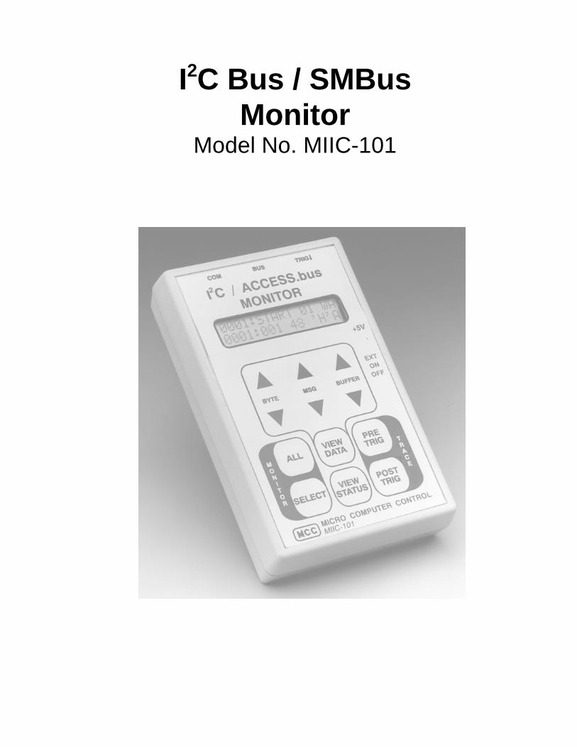
I2C Bus / SMBusMonitor
Model No. MIIC-101

1
Introduction
The I2C Bus / SMBus Monitor is a Troubleshooting Tool for the Inter-Integrated Circuit (I2C) Bus developed by Philips Semiconductors and theSystem Management Bus (SMBus) developed by Intel Corporation. Whenconnected to an I2C Bus or SMBus network, the I2C Bus / SMBus Monitorcan capture and display bus message activity.
The I2C Bus / SMBus Monitor can operate in two modes, stand-alone andremote. In stand-alone mode, the built-in display and keypad supports thecapture and display of bus messages. In remote mode, the monitor iscontrolled by a host computer via an RS-232 serial communications port.
For remote mode operation, MCC offers an optional Windows-based I2CBus / SMBus Analyzer software (#SMB-SW) to provide remote control ofthe monitor from a PC. This software allows bus message data to becaptured, logged, filtered, displayed, and analyzed using one of severalbuilt-in protocol parsers, including the display of Smart Battery System(SBS) messages in engineering units.
In addition to MCC’s standard software, a customer may also developcustom software to meet special processing requirements. Customsoftware can control, collect, and upload bus message data to a hostsystem. This provides a powerful tool for integrating the monitor into anautomatic manufacturing-test environment. Remote control isaccomplished via a series of ASCII text commands. A description of themonitor command set is provided in the Application Program Interfacesection of this manual.
The complete I2C Bus / SMBus Monitor package consists of a hand-heldunit, connecting clip-lead and interface cables, power supply, and optionalWindows-based analyzer software.
I2C Bus / SMBus Monitor
2
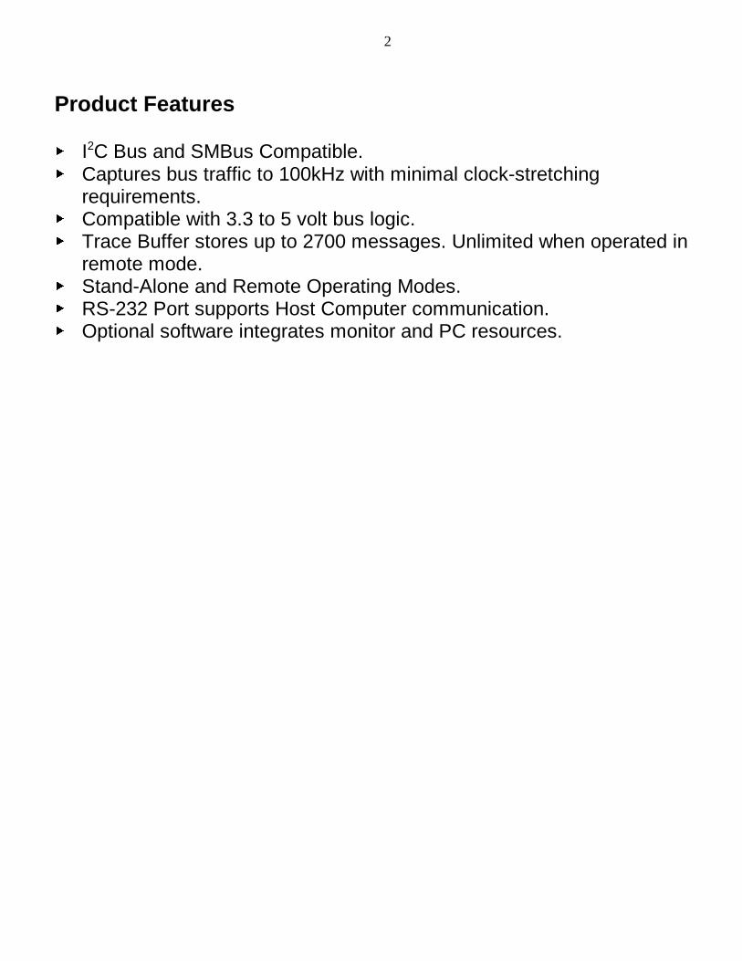
Product Features
� I2C Bus and SMBus Compatible.� Captures bus traffic to 100kHz with minimal clock-stretching
requirements.� Compatible with 3.3 to 5 volt bus logic.� Trace Buffer stores up to 2700 messages. Unlimited when operated in
remote mode.� Stand-Alone and Remote Operating Modes.� RS-232 Port supports Host Computer communication.� Optional software integrates monitor and PC resources.

3
Input / Output Ports
The I2CBus/SMBus Monitor includes three I/O ports (Bus, COM, andTRIG��) for connecting the unit to the network under test and an optionalhost computer system.
This section provides a general description of these I/O ports. For specificport use, see th “Installation” section of this guide.
The monitor provides a Molex Semicon connector (BUS) for connecting tothe I2C Bus or SMBus.
Pin Signal Description1 GND Ground Line2 SDA Data Line3 V Bus +5V (Optional)4 SCL Clock Line
A clip lead cable (#CABCL), included with the unit, provides connection tothe system under test. The Bus +5v line is used to optionally supply orsource power from the target system. See the Power Supply Section forinformation on the use of this line.
I2C Bus / SMBus Port
4
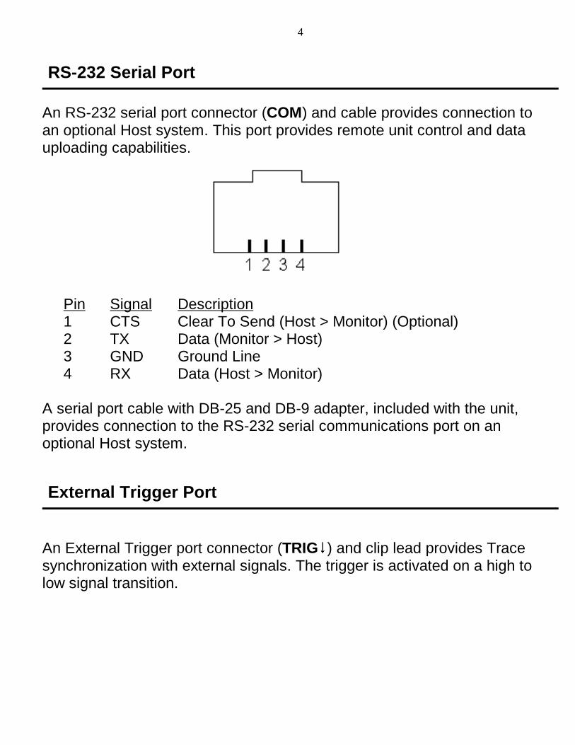
An RS-232 serial port connector (COM) and cable provides connection toan optional Host system. This port provides remote unit control and datauploading capabilities.
Pin Signal Description1 CTS Clear To Send (Host > Monitor) (Optional)2 TX Data (Monitor > Host)3 GND Ground Line4 RX Data (Host > Monitor)
A serial port cable with DB-25 and DB-9 adapter, included with the unit,provides connection to the RS-232 serial communications port on anoptional Host system.
An External Trigger port connector (TRIG��) and clip lead provides Tracesynchronization with external signals. The trigger is activated on a high tolow signal transition.
RS-232 Serial Port
External Trigger Port
5
Set-Up
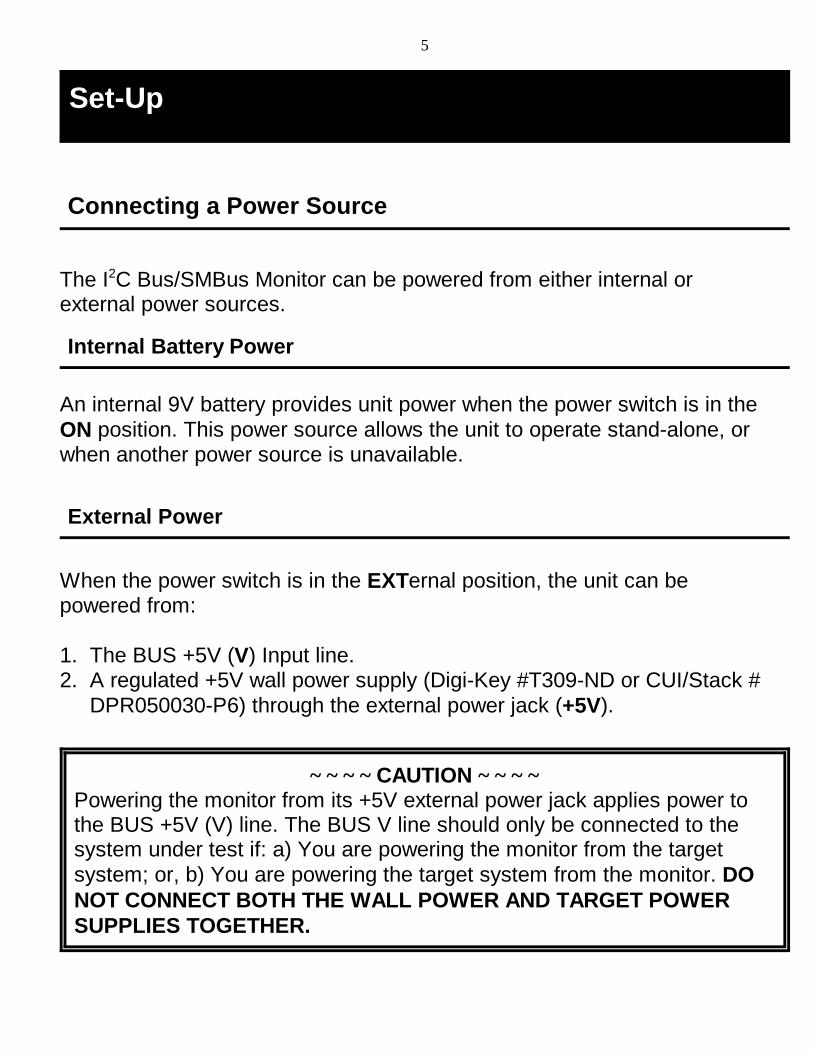
~ ~ ~ ~ CAUTION ~ ~ ~ ~Powering the monitor from its +5V external power jack applies power tothe BUS +5V (V) line. The BUS V line should only be connected to thesystem under test if: a) You are powering the monitor from the targetsystem; or, b) You are powering the target system from the monitor. DONOT CONNECT BOTH THE WALL POWER AND TARGET POWERSUPPLIES TOGETHER.
Internal Battery Power
External Power
The I2C Bus/SMBus Monitor can be powered from either internal orexternal power sources.
An internal 9V battery provides unit power when the power switch is in theON position. This power source allows the unit to operate stand-alone, orwhen another power source is unavailable.
When the power switch is in the EXTernal position, the unit can bepowered from:
1. The BUS +5V (V) Input line.2. A regulated +5V wall power supply (Digi-Key #T309-ND or CUI/Stack #
DPR050030-P6) through the external power jack (+5V).
Connecting a Power Source

6
The unit provides a test clip lead cable for connection to an I2C Bus orSMBus under test. On the monitor, the test clip cable connects to theMolex Semicon modular connector marked BUS.
Test clips are provided for:
Clip ID Signal DescriptionG GND Ground LineD SDA I2C/SMBus Data LineV V +5V (Optional)C SCL I2C/SMBus Clock Line
For information on using the +5v option, see the “Power Supply Section”of this guide.
The monitor provides External Triggering for Trace synchronization withexternal events. Trace synchronization allows bus traffic to be collectedimmediately before or after an electronic event.
A High-to-Low transition on the External Trigger port can be used to starta PRE-TRIG trace, or stop a POST-TRIG trace. See the Trace Modesection of this guide for trace synchronization details.
The Serial Cable provides the connection between the monitor and anoptional Host system. On monitor, the Serial Cable connects to themodular RJ-45 connector marker COM. On the Host system, the cableconnects to a standard RS-232 serial communications port. Both DB-25and DB-9 connectors are supported.
Connecting to an I2C Bus / SMBus
Connecting the External Trigger
Connecting the Serial Cable (optional)
7
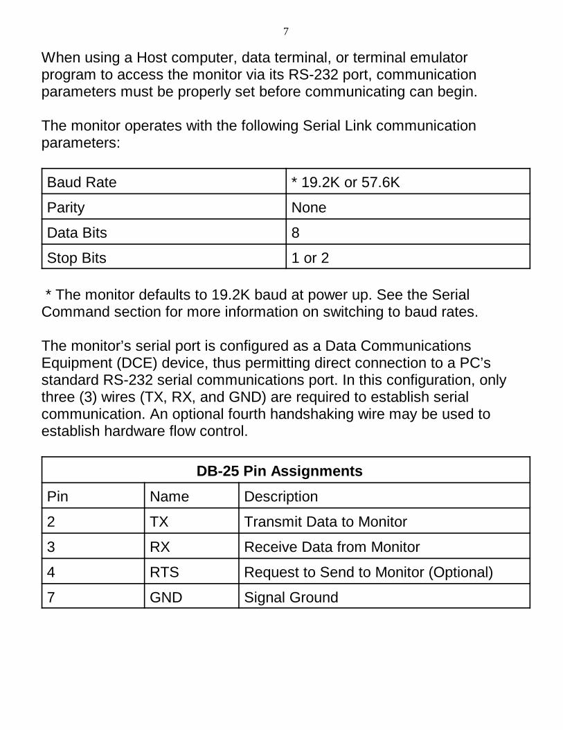
When using a Host computer, data terminal, or terminal emulatorprogram to access the monitor via its RS-232 port, communicationparameters must be properly set before communicating can begin.
The monitor operates with the following Serial Link communicationparameters:
Baud Rate * 19.2K or 57.6K
Parity None
Data Bits 8
Stop Bits 1 or 2
* The monitor defaults to 19.2K baud at power up. See the SerialCommand section for more information on switching to baud rates.
The monitor’s serial port is configured as a Data CommunicationsEquipment (DCE) device, thus permitting direct connection to a PC’sstandard RS-232 serial communications port. In this configuration, onlythree (3) wires (TX, RX, and GND) are required to establish serialcommunication. An optional fourth handshaking wire may be used toestablish hardware flow control.
DB-25 Pin Assignments
Pin Name Description
2 TX Transmit Data to Monitor
3 RX Receive Data from Monitor
4 RTS Request to Send to Monitor (Optional)
7 GND Signal Ground
8
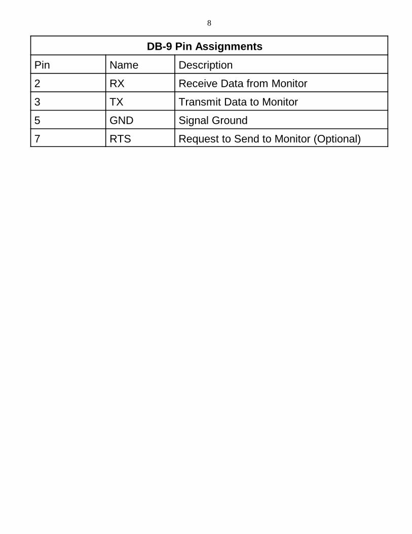
DB-9 Pin Assignments
Pin Name Description
2 RX Receive Data from Monitor
3 TX Transmit Data to Monitor
5 GND Signal Ground
7 RTS Request to Send to Monitor (Optional)

9
Operating Modes
The I2C Bus / SMBus Monitor can operate in two modes, stand-aloneand remote. In stand-alone mode, the built-in display and keypadsupports the capture and display of bus data. In remote mode, themonitor is controlled by a host computer via an RS-232 serialcommunications port.
Quick Start
1. Connect monitor to the target bus.2. Turn monitor power to ON or EXT.3. Select address mode ALL or SELECT.4. Press PRE or POST-TRIG Trace button to begin data capture.
PRE-TRIG waits for TRIG� line low or repeat PRE-TRIG button press.5. Press VIEW-DATA button to end capture and enable BYTE, MSG,
and BUFFER display scroll buttons.
When using the I2C Bus/SMBus Monitor stand-alone, the unit performsdata collection and display using eight (8) operating modes. These modesinclude:
Operation Description
Address Selection Select slave address to monitor
View Status View bus signal logic levels
Trace Capture bus message data
View Data View captured bus data
Remote Capture/Transmit bus data
Simulation Simulate bus message data
Stand-Alone Operation
10
Address Select Mode
View Status Mode
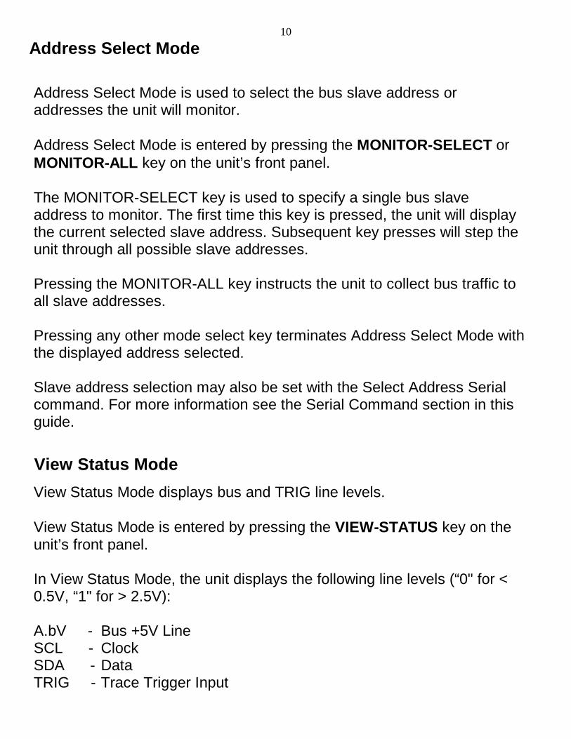
Address Select Mode is used to select the bus slave address oraddresses the unit will monitor.
Address Select Mode is entered by pressing the MONITOR-SELECT orMONITOR-ALL key on the unit’s front panel.
The MONITOR-SELECT key is used to specify a single bus slaveaddress to monitor. The first time this key is pressed, the unit will displaythe current selected slave address. Subsequent key presses will step theunit through all possible slave addresses.
Pressing the MONITOR-ALL key instructs the unit to collect bus traffic toall slave addresses.
Pressing any other mode select key terminates Address Select Mode withthe displayed address selected.
Slave address selection may also be set with the Select Address Serialcommand. For more information see the Serial Command section in thisguide.
View Status Mode displays bus and TRIG line levels.
View Status Mode is entered by pressing the VIEW-STATUS key on theunit’s front panel.
In View Status Mode, the unit displays the following line levels (“0" for <0.5V, “1" for > 2.5V):
A.bV - Bus +5V LineSCL - ClockSDA - DataTRIG - Trace Trigger Input

11
Trace Mode
View Data Mode
Selecting any other operating mode terminates View Status Mode.
In Trace Mode, the unit collects and stores all or selected bus traffic withPRE or POST Trace triggering.
Trace Mode is entered by pressing the PRE-TRIG or POST-TRIG key onthe unit’s front panel. All previously collected data is erased from themonitor’s internal storage. Bus traffic to one or all slave devices iscollected in accordance with the current Address Select Mode definedabove.
Pressing the PRE-TRIG key instructs the unit to start collecting bus trafficupon receiving a trigger signal. Pressing the PRE-TRIG key again, or aHigh-to Low transition on the External Trigger line will trigger datacollection. Once started, PRE-TRIG data collection continues until themonitor’s internal trace buffer is full, or another operating mode isselected.
Pressing the POST-TRIG key instructs the unit to start collecting bustraffic immediately. Once started, POST-TRIG data collection continuesuntil a High-to-Low transition is detected on the External Trigger line, oranother operating mode is selected. Once the trace buffer is full, POST-TRIG tracing continues collecting data by overwriting the oldest storeddata with the newest.
Selecting any other operating mode terminates Trace Mode.
View Data Mode displays data captured during the last trace of busactivity. Displayed information includes:
• Number of Messages : Bytes Captured• Start/Stop Events• Message Number and Message Byte Number• Message Destination Slave Address• Read/Write Requests

12
• Acknowledgments and Negative-Acknowledgments• Transmitted Data in Hex and ASCII• View Data supports forward and reverse scrolling of captured data
bytes or messages.
View Data key/actions include:
Key Action
BYTE-UP - Move Backward one byte.BYTE-DOWN - Move forward one byte.MSG-UP - Move Backward one message.MSG-DOWN - Move Forward one message.BUFFER-UP - Move to Start of buffer.BUFFER-DOWN - Move to End of buffer.
The monitor uses the following display syntax:
I2C Event Display
Start of Buffer [- START OF TRACE -].Start Read w/Ack [MMMM:START AA RA]Data w/Ack [MMMM:NNN DD �C �A]Stop Condition [MMMM:STOP ].End of Buffer [ -- END OF TRACE -- ]
where:
MMMM - Trace Message NumberNNN - Message Byte NumberAA - Device AddressDD - Data in Hexadecimal FormatC - Data in ASCII FormatR/W - Read or Write RequestN/A - Receiver Non/Acknowledgment
13
Remote Mode
Bus Simulation Mode
Selecting any other operating mode terminates View Data Mode.
In Remote Mode, the unit is controlled by a Host computer system via itsserial port. Bus traffic can be collected or uploaded to the Host system forstorage and further analysis.
Remote Mode is entered when the unit receives a Serial Command at itsserial port.
The monitor responds to a variety of Serial Commands including:
• Baud Rate Select• ASCII or Binary Remote Upload Select• Slave Address Select• Dump Trace Buffer• Remote Trace• Help
For more information see the Application Program Interface section in thisguide.
Selecting any other operation mode terminates Remote Mode.
In Bus Simulation Mode, the monitor simulates I2C Bus traffic without abus connection. Emulation provides a learning and testing platformwithout the need for a working bus.
Bus simulation is enabled by pressing the BUFFER-UP key on the unit’sfront panel during the power-up sequence. Once enabled, bus simulationremains in effect until the next unit power-up cycle.

14
During Trace operations, bus simulation repetitively generates thefollowing three bus messages:
10234836536C36C36F500 - Start 02, W, A, “Hello”, Stop10435736F37236C364500 - Start 04, W, A, “World”, Stop2FF500 - Start FE, R, N, Stop
See ASCII Remote Select Serial command for details on ASCII format.
Bus simulation can also be enabled with the Bus Simulation Enable Serialcommand. For more information see the Serial Command section in thisguide.
In remote mode, the monitor is controlled by a host computer via anRS-232 serial communications port. In this mode, bus traffic can becollected or uploaded to the Host system for storage and further analysis.
For remote mode operations, MCC offers Windows-based I2C Bus /SMBus Analyzer software to provide remote control of the monitor. Thissoftware, described below, can be purchased with the monitor in kit form(#MIIC-101K), or the software can be separately purchased (#SMB-SW).
A customer may also develop custom software to meet specialprocessing requirements. Remote control is accomplished via a series ofASCII text commands. A description of the monitor command set isprovided in Appendix C.
Remote Operation

15
I2C Bus / SMBus Analyzer Software
Quick Start
1. Install analyzer software.2. Connect monitor to the target bus.3. Connect monitor to host PC COM port.4. Turn monitor power to ON or EXT.5. Select COM port connected to bus monitor.6. Select bus slave addresses to monitor.7. Click Trace button.
The I2C/SMBus Analyzer Software provides real-time capture and on-screen display of live or previously recorded I2C or SMBus messages. Itis designed to work with the I2C Bus / SMBus Monitor (#MIIC-101). Thesoftware also provides filtering of displayed messages by device slaveaddress, and provides a global display of bus activity over all 7-bit slaveaddresses.
16
Software Installation
For Windows 95 and above:
1. Insert software distribution diskette into floppy drive.2. Select Start|Run. Type "a:setup".3. Follow instructions on screen.
For Windows 3.x or NT 3.51:
1. Insert software distribution diskette into floppy drive.2. Select File|Run. Type "a:setup".3. Follow instructions on screen.
Equipment Setup
1. Connect monitor to a PC COM port - COM:1, 2, 3 or 4.2. Connect monitor to the target I2C Bus using the clip lead cable.3. Turn monitor power ON.
NOTE: Previously collected raw (*.i2c) files may be analyzed off-line. Several such file are automatically installed during product installation. See the File|Load feature below.
Starting The Program
For Windows 95 and above:
1. From Start Menu, select Programs|I2C Bus_SMBus Analyzer.2. Click on I2C Bus_SMBus Analyzer.
For Windows 3.x or NT 3.51:

17
1. From Program Manager double click on the I2C Bus_SMBus AnalyzerProgram Group.
2. Double click on I2C Bus_SMBus Analyzer Program Item.
The I2C/SMBus Analyzer Software can display real-time or previouslyrecorded bus data. To display live data, select the COM port connected tothe Bus Monitor, then click on the Trace Button. To display previouslyrecorded log file data, click File|Load and select a raw I2C (*.i2c) log file.Several sample log files are automatically installed in the software defaultfolder (sub-directory) during software installation.
Program Controls:
I2C/SMBus Analyzer Software program controls consists of onscreenbuttons, check boxes, grid controls, menu items, and dialog boxes. Thissection describes these controls and explains how to use these controlsto capture and display bus message data.
Button Controls:
Trace - This button is available when the ModeSelect|Remote Tracemenu item is selected. Clicking this button puts the monitor into remotetrace mode, and will display real time data captured from the bus.Message data is displayed according to the current slave addresses,display options, and data protocol selected.
Dump - This button is available when the ModeSelect|Dump Buffer menuitem is selected. Clicking this button puts the monitor into dump mode,and will display previously recorded data captured from the bus that isheld in the monitor’s internal buffer. Message data is displayed accordingto the current slave addresses, display options, and data protocolselected.
18
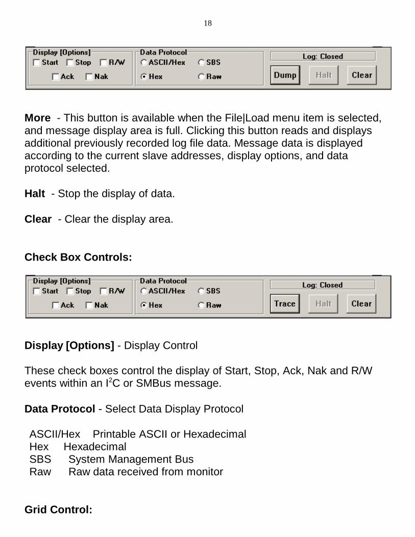
More - This button is available when the File|Load menu item is selected,and message display area is full. Clicking this button reads and displaysadditional previously recorded log file data. Message data is displayedaccording to the current slave addresses, display options, and dataprotocol selected.
Halt - Stop the display of data.
Clear - Clear the display area.
Check Box Controls:
Display [Options] - Display Control
These check boxes control the display of Start, Stop, Ack, Nak and R/Wevents within an I2C or SMBus message.
Data Protocol - Select Data Display Protocol
ASCII/Hex Printable ASCII or HexadecimalHex HexadecimalSBS System Management BusRaw Raw data received from monitor
Grid Control:

19
AddrMap Grid - Select Slave Addresses to Display
Select slave addresses to display and monitor address traffic. Click ongrid cells to Enable (checked) or Disabled (x) slave address for display.Enabled addresses show bus message activity with a red dot. Selectinga grid cell clears traffic indicator.
Menu Controls:
File|Load - Load a File
Load a previously stored file for processing or display. The software canread/process/display log files (*.i2c) previously collected from the monitor,or can read/display any ASCII text (*.txt) file. Message data is displayedaccording to the current slave addresses, display options, and dataprotocol selected. ASCII text files are simply displayed.
File|Save As - Save Data to File
Save the currently displayed data to a file. Up to 32K characters currentlydisplayed can be saved in a log file (*.i2c) or ASCII text (*.txt) file. Savedfiles can be redisplayed using the File|Load menu item.
File|Print Setup - Setup printer.
20
File|Print - Print Displayed Data
Print the currently display data. Up to 32K characters currently displayedare printed.
File|Font Select - Select display font and size.
File|Save Setup - Save Setup Parameters
The following program parameters are saved to the file I2C.INI. Theseparameters are automatically loaded the next time the program is started.ComPort NumberDisplay OptionsProtocol SelectionFont SelectionHints On/Off Selection
AddrMap - Display Address Map Grid
See the AddrMap control definition above.
ComPorts - Select Com Port
Select monitor connected com port and baud rate.
NOTE: The monitor defaults to 19200 baud at power up. Faster baudrates can cause loss of data on some PCs.
ModeSelect|Remote Trace - Select Monitor Remote Mode
Bus messages captured by the monitor are uploaded for display.
ModeSelect|Dump Buffer - Select Monitor Dump Mode
Previously captured bus messages held in the monitor’s internal bufferare uploaded for displayed.

21
ModeSelect|Message Display - Select Message Mode
Bus messages are displayed upon receiving STOP at end of message. This is the default mode and provides fast display of message
data.
ModeSelect|Byte Display - Select Byte Mode
Bus messages are displayed upon receiving each byte of message data. This mode can display partial or incomplete message data when acomplete message is not being transmitted (i.e. missing STOP).
ModeSelect|Show Hints - Enables Program Controls hint display.
Log - Log File Control
Open/close log file (*.i2c) of data received from monitor. Log files canlater be read/processed with the File|Open menu item.
Help|ReadMe - Display technical notes
Help|Revision Report - Display revision report
Help|About - Display software informationThis section is a description for programmers writing custom applications.
22
Application Program Interface
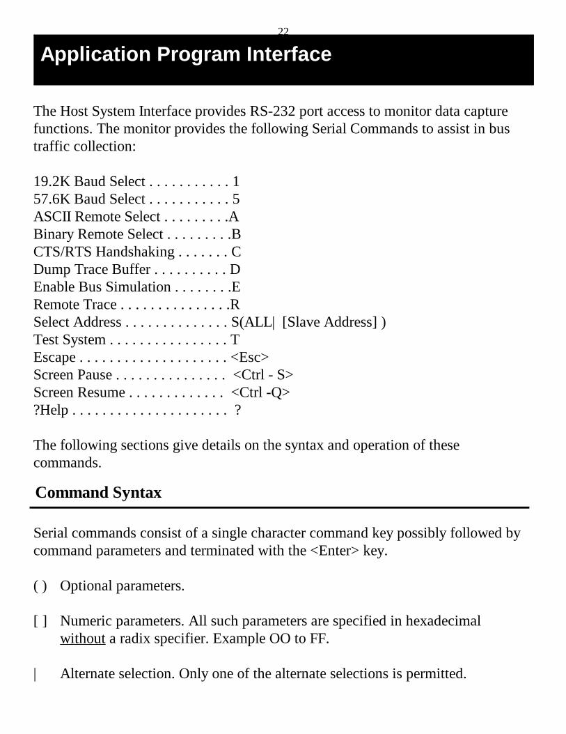
The Host System Interface provides RS-232 port access to monitor data capturefunctions. The monitor provides the following Serial Commands to assist in bustraffic collection:
19.2K Baud Select . . . . . . . . . . . 157.6K Baud Select . . . . . . . . . . . 5ASCII Remote Select . . . . . . . . .ABinary Remote Select . . . . . . . . .BCTS/RTS Handshaking . . . . . . . CDump Trace Buffer . . . . . . . . . . DEnable Bus Simulation . . . . . . . .ERemote Trace . . . . . . . . . . . . . . .RSelect Address . . . . . . . . . . . . . . S(ALL| [Slave Address] )Test System . . . . . . . . . . . . . . . . TEscape . . . . . . . . . . . . . . . . . . . . <Esc>Screen Pause . . . . . . . . . . . . . . . <Ctrl - S>Screen Resume . . . . . . . . . . . . . <Ctrl -Q>?Help . . . . . . . . . . . . . . . . . . . . . ?
The following sections give details on the syntax and operation of thesecommands.
Serial commands consist of a single character command key possibly followed bycommand parameters and terminated with the <Enter> key.
( ) Optional parameters.
[ ] Numeric parameters. All such parameters are specified in hexadecimalwithout a radix specifier. Example OO to FF.
| Alternate selection. Only one of the alternate selections is permitted.
Command Syntax

23
NoteImmediately after issuing a Baud Rate Select command, the Hostsystem serial port must also change to the matching baud rate.
< > Control keys.
Syntax: 1 (9200) | 5(7600)
Description:
The Baud Rate Select command sets the units serial port to 19.2K or 57.6K baud.The unit defaults to 19.2K baud at power-up.
Executing a Remote Trace on high volumes of bus traffic at 19.2K baud maycause loss of data on buffer overflows. Buffer overflows are marked in the datastream with the “???” string.
When executing a Remote Trace at 57.6K baud, the HOST system may lose dataon character overwrites. Character overwrite detection is a function of yourterminal emulation program.
Example: 5 <Enter> - 57.6K baud selected.1 <Enter> - 19.2K baud selected.
Baud Rate Select

24
Syntax: A
Description:
The ASCII Remote Select command configures Remote Trace data to be sent tothe serial port in printable ASCII format. At power-up, ASCII Remote is thedefault transfer mode.
When ASCII Remote in enabled, data is transferred in three-character ASCII sets.The first character specifies the data type, and is followed by a two characterslave address or data.
When executing a Remote Trace, data is sent to the serial port in the followingASCII format:
TAATHH ...THH<CR><LF>
where:
T - Type1 - Start with Acknowledgment.2 - Start without Acknowledgment.3 - Data with Acknowledgment.4 - Data without Acknowledgment.5 - Stop
AA - 8-bit Slave Address (00...FFH).HH - 8-bit Data (00...FFH).
Example: A<Enter>R<Enter>
150320...323500<CR><LF>
where:
ASCII Remote Select

25
1 - Start with Acknowledgment.50 - Slave Address 50H.3 - Data with Acknowledgment.
20 - Data 20H....3 - Data with Acknowledgment.
23 - Data 23H.5 - Stop.
00 - Always 00.
In the above example, a single bus message is uploaded to the Host system inASCII format during a Remote Trace.
Syntax: B
Description:
The Binary Remote Select command configures Remote Trace data to be sent tothe serial port in Binary format.
When Binary Remote is enabled, data is transferred in two-byte binary sets. Thefirst byte specifies the data type, and is followed by a slave address or data byte.
When executing a Remote Trace, data is sent to the serial port in the followingBinary format:
TATH...TH<CR><LF>
where:
T - Type
Binary Remote Select

26
NOTE
The Binary format is reserved for future MCC product support.
1 - Start with Acknowledgment2 - Start without Acknowledgment.3 - Data with Acknowledgment.4 - Data without Acknowledgment.5 - Stop.
A - 8-bit Slave Address (00...FFH).H - 8-bit Data (00...FFH).
Example: B<ENTER>R<ENTER>
150320...323500<CR><LF>
where:
1 - Start with Acknowledgment.50 - Slave Address 50H.3 - Data with Acknowledgment.
20 - Data 20H....3 - Data with Acknowledgment.
23 - Data 23H.5 - Stop.
00 - Always 00.
In the above example, a single bus message is uploaded to the Host system inbinary format during a Remote Trace.
27
Syntax: C
Description:
The CTS/RTS Command is used to toggle Clear-to-Send / Request-to-SendSerial Link flow control. The power-up default condition is CTS/RTSHandshaking disabled.
When enabled, CTS/RTS Handshaking halts monitor serial port output when theHost RTS line is dis-asserted. This feature is useful in preventing serial link dataoverflow on the host system.
The monitor always supports X-ON/X-OFF Serial link flow control. Sending anX-OFF (Ctrl/S) character to the unit halts serial port output. Sending asubsequent X-ON (Ctrl/Q) character causes output to continue. This feature isuseful during a Dump or Remote Trace to temporarily stop data scrolling.
Example: C<Enter> - CTS/RTS Handshaking Enabled
Syntax: D
Description:
The Dump Trace Buffer command sends all bus data collected during the lastPRE-TRIG or POST-TRIG Trace to the serial port. Buffered data is unaltered bythis operation.
Data is sent to the serial port in ASCII format. See the ASCII Remote Selectcommand for format details.
CTS/RTS Handshaking Command
Dump Trace Buffer
28
Dump Trace Buffer terminates upon exhausting the buffer, or upon receiving anEscape <ESC> character on the serial port.
Screen Pause <Ctrl-S> and Screen Resume <Ctrl-Q> are active.
Example: D<Enter>
In the above example, buffered bus messages are uploaded to the Host system inASCII format during a Dump Trace Buffer operation. See the ASCII RemoteSelect command for format details.
Syntax: E
Description:
The Enable Bus Simulation command causes the unit to emulate bus trafficwithout a bus connection. Emulation provides a learning and testing platformwithout the need for a working bus.
Bus simulation repetitively generates the following three messages:
10234836536C36C36F500 - Start #2, “Hello”, Stop10435736F37236C364500 - Start #4, “World”, Stop2FF500 - Start #FFH, Stop
See ASCII Remote Select for details on ASCII format.
Once enabled, bus simulation remains in effect until the next unit power-upcycle.
Bus simulation can also be enabled by pressing the BUFFER-UP key during theunit power-up sequence.
Enable Bus Simulation

29
Example: E<Enter> - Enable Simulation
Syntax: R
Description:
The Remote Trace command places the unit in POST-TRIG Trace Mode, andsends all bus traffic to the serial port.
During a Remote Trace, data in temporarily buffered in the unit, then sent to theserial port in the currently selected ASCII or Binary format. See the ASCIIRemote Select or Binary Remote Select commands for data format details.
Remote Trace terminates upon receiving a High-to-Low transition on theExternal Trigger line or an Escape <Esc> character on the serial port.
Screen Pause <Ctrl-S> and Screen Resume <Ctrl-Q> are active.
Example: R<Enter> - Start Remote Trace
In the above example, bus messages are buffered and uploaded to the Hostsystem in the selected ASCII or Binary format. See the ASCII Remote Select or
Binary Remote Select commands for data format details.
Syntax: S(ALL | [Slave Address] )
Remote Trace
Select Address

30
NOTE
The Test System command is reserved for MCC manufacturing andsupport use only.
Description:
The Select Address command is used to select the bus slave address or addressesthe unit will monitor. During a PRE-TRIG, POST-TRIG, or Remote Trace, theunit will capture all messages sent to this address.
Entering parameter ALL instructs the unit to collect bus traffic to all slaveaddresses.
Entering a slave address parameter specifies a single bus address to monitor.
Slave address selection may also be set with the MONITOR-SELECT orMONITOR-ALL keys. For more information see the “Introduction” section inthis guide.
Example: SALL<Enter> - Monitor ALL Slave addresses.
S50<Enter> - Monitor slave address 50H.
Syntax: T
Description:
The Test System command invokes manufacturing test functions. This commandis reserved for MCC use only.
Test System
31
Syntax: ?
Description:
The Help command displays the syntax for Monitor command set.
Example: ?<Enter> - display monitor Help Screen
Help

32
Appendix A - Solving Problems
If you suspect a malfunctioning unit follow the steps described below beforecontacting MCC for additional assistance.
Problem:
Unit does not display the sign-on message on the internal LCD display atPower-up.
Solution:
1. Check the unit power supply. If the power switch is in the ON position, theunit is powered by the internal 9V battery. Check and replace a faulty battery.
2. If the switch is in the EXTernal position, the unit can be powered by 5VACCESS.bus power, the Test Cable A.bV external power lead, or an external5V wall transformer. Check and replace any faulty power source.
Problem:
Unit does not display the sign-on message on the Serial Link at Power-up.
Solution:
1. Check the Serial Link at unit and Host system.2. Confirm that the unit and Host system are communicating at the same baud
rate and with the proper communication parameters.
Solving Problems

33
Problem:
Unit does not collect bus traffic in Trace Mode.
Solution:
1. Check cable connections at the unit and bus. When using the Test Cable,confirm SCL, SDA, and GND clip leads are connected to appropriate buslines.
2. Check Selected Address. If a single bus address is specified, only messagesdirected to that address will be collected. Confirm presence of bus traffic bymonitoring all bus addresses.
3. When using the External Trigger Port, the unit will wait for a trigger event.Check the TRIG input using Line Status Mode. A High-to Low transition,with minimum 2usec Low duration, is required to generate a triggercondition.

34
Appendix B - Operating Specifications
Parameter Min Typ Max Unit
Temperature Range
Operating Temperature 0 +50� CStorage Temperature -25 +70� C
D.C. Characteristics
External Power -5% 5 +5% VInput Current 20 40 mAInternal Battery 9 V
SDA and SCL (I2C Signals)Input Low Voltage -.05 +1.5 VInput High Voltage +3.5 -5.5 VInput Leakage Current +-20 uAInput Capacitancew/o Test Cable 20 pFwith Test Cable 60 pF
Trigger InputInput Low Voltage -0.5 +0.9 VInput High Voltage +1.9 +5.5 VInput Current 100 uAInput Capacitance 20 60 pF
Operating Specifications

35
Appendix C - Serial Port Commands
Command Syntax Description
Baud Rate Select 1<CR>5<CR>
19.2K baud select57.6K baud select
ASCII ProtocolSelect
A<CR> Configure Remote Trace tosend trace data in ASCIIformat.
Binary ProtocolSelect
B<CR> Configure Remote Trace tosend trace data in binaryformat.
CTS/RTS FlowControl
C<CR> Toggle Clear To Send (CTS) /Request To Send (RTS)RS-232 port flow control.
Dump Trace Buffer D<CR> Dump pre-recorded messagetrace data in ASCII format.
Enable Simulation E<CR> Simulate bus message trafficwithout a bus connection.
Serial Port Commands

36
Remote Trace R<CR> Place monitor in POST-TRIGtrace mode and sends allcaptured bus traffic to theserial port in the currentselected format (ASCII orBinary).
Slave Address Select SALL<CR>Sxx<CR>
Monitor allMonitor single slave address
System Test T<CR> Enter test mode
?Help ?<CR> Display monitor help


