88
i-PILOT ® LINK ™ for HELIX ® Operations Guide 532556-1EN_A

i-PILOT®LINK™ for HELIX®
Operations Guide532556-1EN_A

2
THANK YOU!Thank you for choosing Humminbird®, the #1 name in marine electronics. Humminbird has built its reputation by designing andmanufacturing top quality, thoroughly reliable marine equipment. Your Humminbird is designed for trouble-free use in even the harshestmarine environment. In the unlikely event that your Humminbird does require repairs, we offer an exclusive Service Policy. For completedetails, see the separate warranty card included with your unit. We encourage you to read this operations manual carefully in order to getthe full benefit from all the features and applications of your Humminbird product.
Contact Humminbird Customer Service at humminbird.com or call 1-800-633-1468.
WARNING! This product contains chemicals known to the State ofCalifornia to cause cancer and birth defects or other reproductiveharm.
WARNING! This device should not be used as a navigational aidto prevent collision, grounding, boat damage, or personal injury.When the boat is moving, water depth may change too quickly toallow time for you to react. Always operate the boat at very slowspeeds if you suspect shallow water or submerged objects.
WARNING! The electronic chart in your Humminbird unit is anaid to navigation designed to facilitate the use of authorizedgovernment charts, not to replace them. Only officialgovernment charts and notices to mariners contain all of thecurrent information needed for the safety of navigation, and thecaptain is responsible for their prudent use.
WARNING! Humminbird is not responsible for the loss of datafiles (waypoints, routes, tracks, groups, recordings, etc.) thatmay occur due to direct or indirect damage to the unit’shardware or software. It is important to back up your controlhead’s data files periodically. Data files should also be saved toyour PC before restoring the control head defaults or updatingthe software. See your Humminbird online account athumminbird.com and the HELIX Operations Manual for details.
WARNING! Disassembly and repair of this electronic unit shouldonly be performed by authorized service personnel. Anymodification of the serial number or attempt to repair the originalequipment or accessories by unauthorized individuals will void thewarranty.
WARNING! Do NOT leave the control head microSD or SD cardslot cover open. The slot cover should always be closed toprevent water damage to the unit.
WARNING! Do not travel at high speed with the unit coverinstalled on the HELIX 5 or HELIX 7 control head. Remove theunit cover before traveling at speeds above 20 mph.
WARNING! You are responsible for the safe and prudentoperation of your vessel. We have designed i-Pilot Link to be anaccurate and reliable tool that will enhance boat operation andimprove your ability to catch fish. This product does not relieveyou from the responsibility for safe operation of your boat. Youmust avoid hazards to navigation and always maintain apermanent watch so you can respond to situations as theydevelop. You must always be prepared to regain manual controlof your boat.
WARNING! Take care that neither you nor other personsapproach the turning propeller too closely, neither with bodyparts nor with objects. The motor is powerful and may endangeror injure you or others. While the motor is running, watch out forpersons swimming and for floating objects. Persons whoseability to run the motor or whose reactions are impaired byalcohol, drugs, medication, or other substances are notpermitted to use the motor. See your i-Pilot Link Owner’sManual for details.
WARNING! It is recommended to only use Johnson Outdoorsapproved accessories with your Minn Kota motor, such as thisi-Pilot Link system. Using non-approved accessories includingto mount or control your motor may cause damage, unexpectedmotor operation and injury. Be sure to use the product andapproved accessories, including remotes, safely and in themanner directed to avoid accidental or unexpected motoroperation. Keep all factory installed parts in place includingmotor and accessory covers, enclosures and guards.
WARNING! Be sure to know how to power the motor on and off,and always be alert for unexpected motor movement, such as aturning propeller. Read this manual and the i-Pilot Link Owner’sManual for details.
WARNING! Due to safety reasons, the i-PIlot Link will not engagea position farther than 1/4 mile away.
CAUTION! The i-Pilot Link uses a magnetic compass to detectdirection of travel. The compass can be adversely affected bymagnets or large, ferrous metal objects near (within 24” of) thetrolling motor control head. See the i-Pilot Link Owner’s Manualfor details.
Obstructions on the propeller may cause excessive vibration ofthe motor head. This vibration can cause the compass to wanderand erratic steering to occur. Clear the obstruction to return themotor and i-Pilot Link system to normal operation. See your i-Pilot Link Owner’s Manual for details.

3
FCC NOTICE: This device complies with Part 15 of the FCC Rules.Operation is subject to the following two conditions: (1) this devicemay not cause harmful interference, and (2) this device must acceptany interference received, including interference that may causeundesired operation.
CAUTION! This equipment has been tested and found to complywith the limits for a Class B digital device, pursuant to Part 15 ofthe FCC Rules. These limits are designed to provide reasonableprotection against harmful interference in a residentialinstallation. This equipment generates, uses and can radiateradio frequency energy and, if not installed and used inaccordance with the instructions, may cause harmfulinterference to radio communications. However, there is noguarantee that interference will not occur in a particularinstallation. If this equipment does cause harmful interferenceto radio or television reception, which can be determined byturning the equipment off and on, the user is encouraged to tryto correct the interference by one or more of the followingmeasures:
• Reorient or relocate the receiving antenna.
• Increase the separation between the equipment and receiver.
• Connect the equipment into an outlet on a circuit different fromthat to which the receiver is connected.
• Consult the dealer or an experienced radio/TV technician forhelp.
Class B Device (Broadcasting and communication equipment forhome):
CAUTION! This equipment is home use (Class B) electromagneticwave suitability equipment and to be used at home and it can beused in all areas.
NOTE: Some features discussed in this manual require aseparate purchase, and some features are only available oninternational models. Every effort has been made to clearlyidentify those features. Please read the manual carefully inorder to understand the full capabilities of your model.
NOTE: The illustrations in this manual may not look the same asyour product, but your unit will function in a similar way.
NOTE: To purchase accessories for your control head, visit ourWeb site at humminbird.com or contact Humminbird CustomerService at 1-800-633-1468.
NOTE: The procedures and features described in this manual aresubject to change without notice. This manual was written inEnglish and may have been translated to another language.Humminbird is not responsible for incorrect translations ordiscrepancies between documents.
NOTE: Product specifications and features are subject to changewithout notice.
NOTE: Humminbird verifies maximum stated depth in saltwaterconditions, however actual depth performance may vary due totransducer installation, water type, thermal layers, bottomcomposition, and slope.
ROHS STATEMENT: Product designed and intended as a fixedinstallation or part of a system in a vessel may be considered beyondthe scope of Directive 2002/95/EC of the European Parliament and ofthe Council of 27 January 2003 on the restriction of the use of certainhazardous substances in electrical and electronic equipment.
ENVIRONMENTAL COMPLIANCE STATEMENT: It is the intention ofJohnson Outdoors Marine Electronics, Inc. to be a responsiblecorporate citizen, operating in compliance with known and applicableenvironmental regulations, and a good neighbor in the communitieswhere we make or sell our products.
WEEE DIRECTIVE: EU Directive 2002/96/EC “Waste of Electrical andElectronic Equipment Directive (WEEE)” impacts most distributors,sellers, and manufacturers of consumer electronics in the EuropeanUnion. The WEEE Directive requires the producer of consumerelectronics to take responsibility for the management of waste fromtheir products to achieve environmentally responsible disposal duringthe product life cycle.
WEEE compliance may not be required in your location for electrical &electronic equipment (EEE), nor may it be required for EEE designedand intended as fixed or temporary installation in transportationvehicles such as automobiles, aircraft, and boats. In some EuropeanUnion member states, these vehicles are considered outside of thescope of the Directive, and EEE for those applications can beconsidered excluded from the WEEE Directive requirement.
This symbol (WEEE wheelie bin) on product indicates theproduct must not be disposed of with other household refuse. Itmust be disposed of and collected for recycling and recovery ofwaste EEE. Johnson Outdoors Marine Electronics, Inc. will mark
all EEE products in accordance with the WEEE Directive. It is our goal tocomply in the collection, treatment, recovery, and environmentallysound disposal of those products; however, these requirements do varywithin European Union member states. For more information aboutwhere you should dispose of your waste equipment for recycling andrecovery and/or your European Union member state requirements,please contact your dealer or distributor from which your product waspurchased.
AUTOCHART®, AUTOCHART® LIVE, AutoPilot™, HELIX®, Humminbird®, i-Pilot® Link™, LakeMaster®, Minn Kota®, Riptide®, Terrova™, Ulterra™, X-Press™ Menu, and ZeroLine MapCard™ are trademarked by or registered trademarks of Johnson Outdoors Marine Electronics, Inc.
Adobe, Acrobat, Adobe PDF, and Reader are either registered trademarks or trademarks of Adobe Systems Incorporated in the United States and/or other countries.
Baekmuk Batang, Baekmuk Dotum, Baekmuk Gulim, and Baekmuk Headline are registered trademarks owned by Kim Jeong-Hwan.
© 2017 Johnson Outdoors Marine Electronics, Inc. All rights reserved.

4
TABLE OF CONTENTSWarnings 2
Introduction 7
Installation 8
Purchase Ethernet Cables and Equipment . . . . . . . . . . . . . . . . . . 8
Confirm Installation of i-Pilot Link Controller and Remote . . . . 8
Connect the i-Pilot Link to the HELIX Control Head . . . . . . . . . . 9
Confirm i-Pilot Link Installation and Connectionon the HELIX Control Head . . . . . . . . . . . . . . . . . . . . . . . . . . . . . 10
Confirm the i-Pilot Link Connection . . . . . . . . . . . . . . . . . . . . . . .10
Check GPS Reception . . . . . . . . . . . . . . . . . . . . . . . . . . . . . . . . . . . 11
Update Software 12
Export Navigation Data . . . . . . . . . . . . . . . . . . . . . . . . . . . . . . . . . . 12
Register your Humminbird Products . . . . . . . . . . . . . . . . . . . . . . 12
Update the Control Head Software . . . . . . . . . . . . . . . . . . . . . . . .13
Restart the System . . . . . . . . . . . . . . . . . . . . . . . . . . . . . . . . . . . . . 13
Configure i-Pilot Link with the Control Head 14Open the i-Pilot Settings Menu . . . . . . . . . . . . . . . . . . . . . . . . . . .14
Enable i-Pilot Link Navigation . . . . . . . . . . . . . . . . . . . . . . . . . . . . .14
Turn on Auto Upload Data . . . . . . . . . . . . . . . . . . . . . . . . . . . . . . . .15
Turn on/off Prop Auto On . . . . . . . . . . . . . . . . . . . . . . . . . . . . . . . . .15
Set the Arrival Mode . . . . . . . . . . . . . . . . . . . . . . . . . . . . . . . . . . . . .15
Install a Map Card (optional) . . . . . . . . . . . . . . . . . . . . . . . . . . . . . .16
Set the Water Level Offset . . . . . . . . . . . . . . . . . . . . . . . . . . . . . . . .17
Adjust i-Pilot Link Alarms 18Adjust the i-Pilot Pre-Arrival Alarm . . . . . . . . . . . . . . . . . . . . . . . .18
Adjust the i-Pilot Off Course (XTE) Alarm . . . . . . . . . . . . . . . . . .19
Display Digital Readout Boxes 20
Display Humminbird LakeMasterContour Lines and Depth Ranges 22Show/Hide Contour Lines . . . . . . . . . . . . . . . . . . . . . . . . . . . . . . . .23
Turn on Depth Colors . . . . . . . . . . . . . . . . . . . . . . . . . . . . . . . . . . . .23
Highlight a Depth Range . . . . . . . . . . . . . . . . . . . . . . . . . . . . . . . . .23
Highlight a Shallow Water Range . . . . . . . . . . . . . . . . . . . . . . . . . .23
Deploy or Stow the Ulterra Trolling Motor 24Deploy the Motor . . . . . . . . . . . . . . . . . . . . . . . . . . . . . . . . . . . . . . . .24
Stow the Motor . . . . . . . . . . . . . . . . . . . . . . . . . . . . . . . . . . . . . . . . . .24
Pause Deploying or Stowing . . . . . . . . . . . . . . . . . . . . . . . . . . . . . .24
Adjust the Trim . . . . . . . . . . . . . . . . . . . . . . . . . . . . . . . . . . . . . . . . . .24
i-Pilot Link Navigation Overview 25Open the Chart View . . . . . . . . . . . . . . . . . . . . . . . . . . . . . . . . . . . . .25
Open the i-Pilot X-Press Remote . . . . . . . . . . . . . . . . . . . . . . . . . .26
Start i-Pilot Link Navigation . . . . . . . . . . . . . . . . . . . . . . . . . . . . . .29
Cancel i-Pilot Link Navigation (Disengage) . . . . . . . . . . . . . . . . .30
Mark i-Pilot Link Navigation . . . . . . . . . . . . . . . . . . . . . . . . . . . . . .30
Propeller Controls 31Start or Stop the Propeller . . . . . . . . . . . . . . . . . . . . . . . . . . . . . . .31
Steer . . . . . . . . . . . . . . . . . . . . . . . . . . . . . . . . . . . . . . . . . . . . . . . . . . .32
Increase or Decrease Speed . . . . . . . . . . . . . . . . . . . . . . . . . . . . . .33
Engage High Speed Bypass (HSB) . . . . . . . . . . . . . . . . . . . . . . . . .34
Cruise Control 35
Spot-Locks 37Mark and Save a Spot-Lock . . . . . . . . . . . . . . . . . . . . . . . . . . . . . .38
Start Spot-Lock Navigation . . . . . . . . . . . . . . . . . . . . . . . . . . . . . .38
Jog Spot-Lock (Heading Sensor Required) . . . . . . . . . . . . . . . . .42
Cancel Navigation (Disengage) . . . . . . . . . . . . . . . . . . . . . . . . . . .44
Delete a Saved Spot-Lock in the Chart View . . . . . . . . . . . . . . . .44
Edit a Saved Spot-Lock . . . . . . . . . . . . . . . . . . . . . . . . . . . . . . . . . .44
Convert a Spot-Lock to a Waypoint . . . . . . . . . . . . . . . . . . . . . . . .45
Show/Hide a Spot-Lock . . . . . . . . . . . . . . . . . . . . . . . . . . . . . . . . . .45
Waypoints 46Mark a Waypoint . . . . . . . . . . . . . . . . . . . . . . . . . . . . . . . . . . . . . . . .46
Start Navigation to a Saved Waypoint or Position . . . . . . . . . . .48
Cancel Navigation (Disengage) . . . . . . . . . . . . . . . . . . . . . . . . . . .49
Delete a Saved Waypoint in the Chart View . . . . . . . . . . . . . . . . .49
Edit a Saved Waypoint . . . . . . . . . . . . . . . . . . . . . . . . . . . . . . . . . . .49
Convert a Waypoint to a Spot-Lock . . . . . . . . . . . . . . . . . . . . . . . .51
Show/Hide a Waypoint . . . . . . . . . . . . . . . . . . . . . . . . . . . . . . . . . . .51
Circle Mode 52Navigate in Circle Mode . . . . . . . . . . . . . . . . . . . . . . . . . . . . . . . . . .53
Adjust Circle Mode Settings . . . . . . . . . . . . . . . . . . . . . . . . . . . . . .55
Cancel Navigation (Disengage) . . . . . . . . . . . . . . . . . . . . . . . . . . .55
iTracks 56Record an iTrack . . . . . . . . . . . . . . . . . . . . . . . . . . . . . . . . . . . . . . . .58
Navigate a Saved iTrack . . . . . . . . . . . . . . . . . . . . . . . . . . . . . . . . . .59
Cancel Navigation (Disengage) . . . . . . . . . . . . . . . . . . . . . . . . . . .61
Move a Saved iTrack . . . . . . . . . . . . . . . . . . . . . . . . . . . . . . . . . . . . .61
Delete a Saved iTrack . . . . . . . . . . . . . . . . . . . . . . . . . . . . . . . . . . . .62
Edit a Saved iTrack . . . . . . . . . . . . . . . . . . . . . . . . . . . . . . . . . . . . . .63
Show/Hide an iTrack . . . . . . . . . . . . . . . . . . . . . . . . . . . . . . . . . . . . .63
BackTrack 64Adjust the BackTrack Distance . . . . . . . . . . . . . . . . . . . . . . . . . . . .64
Start BackTrack Navigation . . . . . . . . . . . . . . . . . . . . . . . . . . . . . . .64
Cancel Navigation (Disengage) . . . . . . . . . . . . . . . . . . . . . . . . . . .64

5
TABLE OF CONTENTSFollow the Contour 66
Preparation . . . . . . . . . . . . . . . . . . . . . . . . . . . . . . . . . . . . . . . . . . . . .66
Start Follow the Contour Navigation . . . . . . . . . . . . . . . . . . . . . . .68
Follow an Offset Distance from a Contour . . . . . . . . . . . . . . . . . .70
Follow Bottom Hardness or Vegetation . . . . . . . . . . . . . . . . . . . .70
Routes 72Create a Route and Start Navigation . . . . . . . . . . . . . . . . . . . . . .72
Save the Current Route . . . . . . . . . . . . . . . . . . . . . . . . . . . . . . . . . .73
Cancel Navigation (Disengage) . . . . . . . . . . . . . . . . . . . . . . . . . . .73
Start Navigation on a Saved Route . . . . . . . . . . . . . . . . . . . . . . . .73
Edit a Saved Route . . . . . . . . . . . . . . . . . . . . . . . . . . . . . . . . . . . . . .74
Show/Hide a Route . . . . . . . . . . . . . . . . . . . . . . . . . . . . . . . . . . . . . .74
AutoPilot 75Advanced AutoPilot . . . . . . . . . . . . . . . . . . . . . . . . . . . . . . . . . . . . . .76
Legacy AutoPilot . . . . . . . . . . . . . . . . . . . . . . . . . . . . . . . . . . . . . . . .77
AutoPilot Overview . . . . . . . . . . . . . . . . . . . . . . . . . . . . . . . . . . . . . . .78
Start AutoPilot Navigation . . . . . . . . . . . . . . . . . . . . . . . . . . . . . . . .78
Adjust the Heading . . . . . . . . . . . . . . . . . . . . . . . . . . . . . . . . . . . . . .80
Cancel Navigation . . . . . . . . . . . . . . . . . . . . . . . . . . . . . . . . . . . . . . .81
Manage your i-Pilot Link Navigation Data 82Overview . . . . . . . . . . . . . . . . . . . . . . . . . . . . . . . . . . . . . . . . . . . . . . . .82
Open the Spot-Lock Submenu . . . . . . . . . . . . . . . . . . . . . . . . . . . .85
Open the iTrack Submenu . . . . . . . . . . . . . . . . . . . . . . . . . . . . . . . .86
Export Nav Data . . . . . . . . . . . . . . . . . . . . . . . . . . . . . . . . . . . . . . . . .87
Contact Humminbird 88

6

7 Introduction
INTRODUCTIONOverview
Thank you for purchasing the Minn Kota i-Pilot Link. This revolutionary boat control system enables your Minn Kota trolling motorand your HELIX control head to communicate with each other, delivering unprecedented levels of automatic navigation. Find, store,and revisit your most productive fishing spots and tracks, taking control of it all from either the i-Pilot Link wireless remote controlor directly from the HELIX control head. Add an i-Pilot compatible Humminbird LakeMaster map card or AutoChart ZeroLine mapcard, and unlock the ability to automatically follow depth contours for even higher levels of boat control. All with GPS accuracy soyou spend less time positioning your boat and more time catching fish.
Safety and Cautions while using i-Pilot LinkIn addition to this manual, it is important to thoroughly read the i-Pilot Link Owner’s Manual. Follow all instructions and heed allsafety and cautionary notices. Use of this product is only permitted for persons that have read and understood the user instructions.
WARNING! You are responsible for the safe and prudent operation of your vessel. We have designed i-Pilot Link to be an accurateand reliable tool that will enhance boat operation and improve your ability to catch fish. This product does not relieve you fromthe responsibility for safe operation of your boat. You must avoid hazards to navigation and always maintain a permanent watchso you can respond to situations as they develop. You must always be prepared to regain manual control of your boat.
Learn to operate your i-Pilot Link in an area free from hazards and obstacles.
i-Pilot Link Warranty and RegistrationFor complete details about the i-Pilot Link warranty and product registration, see the i-Pilot Link Owner’s Manual.
HELIX Control HeadThis accessory manual describes the functionality that is added to your HELIX control head when it is connected to the Minn Kotai-Pilot Link. For additional information about the HELIX control head operations, see the HELIX Operations Manual. To download themanual from our Web site, go to humminbird.com.

8Installation
INSTALLATIONUse the following instructions to connect the i-Pilot Link to the HELIX control head. Before proceeding with this installation, the Humminbird control head and Minn Kota trolling motor should be installed. To download the installation guides, visitminnkotamotors.com and humminbird.com.
1 | Purchase Ethernet Cables and Equipment
The i-Pilot Link connects to the HELIX control head Ethernet port or the Humminbird Ethernet Switch. To purchase Ethernet switches,Ethernet cables, and extension cables, visit our Web site at humminbird.com (select Products > Accessories > Networking).
To plan the required cable length, it is important to consider the following:
• The cables will be routed from the trolling motor to the HELIX control head (or Ethernet Switch).
• The cables should be routed through an established routing system on the boat, in an area with minimal interference. Inspectthe selected route carefully to ensure that there are no sharp edges, obstacles, or obstructions that may damage the cables.
• The cables will move with the trolling motor when it is deployed and retracted, so it is important to allow enough length formovement. Check the Ulterra when it is completely vertical, at its highest point (before trim) and at its lowest point.
2 | Confirm Installation of i-Pilot Link Controller and Remote
1. Use your i-Pilot Link Owner’s Manual to confirm the trolling motor is correctly installed and mounted to the bow of the boat.
2. The boat and trolling motor must be located outside and have a direct view of the sky to obtain GPS satellite signals.
WARNING! See the i-Pilot Link Owner’s Manual for installation details and safety information.
3. Verify that all obstructions are away from the propeller in all directions in both the stowed and deployed positions.
4. Connect power to the trolling motor.
5. Deploy the motor so the motor shaft is completely vertical.
6. The i-Pilot Link controller will emit four short beeps on startup.
7. Turn off the power source.
Hardware Ethernet Cables
HELIX Control Heads AS EC QDE (adapter cable) and AS EC Ethernet Cable (AS EC 10E, AS EC 20E, etc.)
Ethernet Switch(AS ETH 5PXG)
AS EC Ethernet Cable* (AS EC 10E, AS EC 20E, etc.)
Various cable lengths are available. Visit our Web site at humminbird.com for more details.

9 Installation
3 | Connect the i-Pilot Link to the HELIX Control Head
Use the following instructions to connect the i-Pilot Link to the installed HELIX control head. If you purchased the HumminbirdEthernet Switch, install it using the instructions in the included installation guide.
WARNING! The power source must be turned off before you proceed with the installation.
1. Confirm that all power sources are turned off.
2. Locate the Ethernet cable on the i-Pilot Link.
3. Connect the adapter cable (AS EC QDE) and extension cable to the Ethernet cable on the i-Pilot Link.
On round connectors, hand-tighten the screw nut.
4. Route the cable to the HELIX control head or Ethernet Switch.
NOTE: The cable should be routed through an established routing system on the boat, in an areawith minimal interference. Inspect the selected route carefully to ensure that there are no sharpedges, obstacles, or obstructions that may damage the cables.
5. Ethernet Switch: Connect the Ethernet cable connector to an available Ethernet port. Hand tighten the screw nut.
HELIX Control Head: Connect the Ethernet cable connector to the Ethernet port on the control head or insert it into theEthernet slot on the cable tray. See the following illustrations and your control head installation guide for details.
NOTE: The ports are keyed to prevent reversed installation, so be careful not to force the connectors into the connector ports.
Hand-Tightening the Screw Nuton the Ethernet Cable
screw nut
The connector is keyed to prevent incorrect installation.
HELIX 9, 10, 12 Cable Tray
PowerCOM
(communications) Transducer
Optional: Use a Y-Cableto connect Transducer andSpeed Sensor Accessory
PowerCOM
(communications)Transducer
HELIX 7 Control Head Ports
Ethernet
Ethernet Temp/Speedpin pin

10Installation
4 | Confirm i-Pilot Link Connection on the HELIX Control Head
After connecting the i-Pilot Link to the HELIX control head, it is important to confirm the connection on the HELIX control head. Allequipment should be connected and powered before you turn on the HELIX control head.
1. Turn on the power source and i-Pilot Link equipment.
2. On the HELIX control head, press the POWER key.
3. When the Title screen is displayed, press the MENU key.
4. Select Normal. Press the RIGHT Cursor key.
5 | Confirm the i-Pilot Link Connection
1. Press and hold the VIEW key.
2. Select System > Accessory Test.
Confirm the i-Pilot is listed as Connected. It may take up to one minute for the i-Pilot to be detected.
Unconnected: If it is listed as Unconnected, check the cable and power connections to confirm they are secure and poweredon. Review the installation guide that was included with your i-Pilot Link to confirm it is installed correctly.
NOTE: The menus for installed accessories are typically included in the Accessories tab in the Main Menu. See your accessoryguide for details. For the latest list of accessories that are compatible with your control head, visit our Web site athumminbird.com.
Confirming i-Pilot Link is Connected
connected
unconnected(not detectedby the controlhead)

11 Installation
6 | Check GPS Reception
Use the instructions in this section to confirm the control head has GPS reception.
1. Press and hold the VIEW key.
2. Select System > GPS Diagnostic View.
Confirm GPS Fix Type is shown as Enhanced or 3D.
Confirm that the latitude/longitude position readout is displayed.
NOTE: To confirm the GPS signal on the i-Pilot Link, see the i-Pilot Link Owner’s Manual.
Reviewing GPS Reception
active satellite signal strength (yellow)
fix type shown asenhanced
latitude/longitudeposition
monitored satellitesignal strength
(gray)

12Update Software
UPDATE SOFTWAREYour control head model may need a software update to work with the i-Pilot Link. We recommend that you read the followingsection completely before starting any software updates.
Control Head Software: Version 1.35 or later is required to use the i-Pilot Link with the HELIX control head. To check the softwareversion installed on your control head, press and hold the VIEW key. Select System > Accessory Test.
i-Pilot Link Remote and Controller: See your i-Pilot Link Owner’s Manual to update the software on the remote and controller.
Supplies: In addition to your Humminbird equipment, you will need a PC with Internet access and a blank SD card or microSD card.
Customer Service: If you have any questions about the software update process, contact Customer Service by visiting our Web siteat humminbird.com or by calling 1-800-633-1468.
1 | Export Navigation Data
Before the HELIX control head software is updated or restored to system defaults, export your navigation data.
WARNING! Humminbird is not responsible for the loss of data files (waypoints, routes, tracks, groups, snapshots, recordings, etc.)that may occur due to direct or indirect damage to the unit’s hardware or software. It is important to back up your control head’sdata files periodically. Data files should also be saved to your PC before restoring the unit’s defaults or updating the software.
1. Install the SD card or microSD card according to the instructions in your control head operations manual.
For card compatibility type, see your control head operations manual.
2. Power on the control head.
3. Main Menu: Press the MENU key twice. Select the Nav tab.
4. Select Waypoints, Routes, Tracks. Press the RIGHT Cursor key.
5. Select Options > Select All and... > Export.
6. Follow the on-screen prompts to confirm or cancel the export.
2 | Register your Humminbird Products
Set up an online account and register your Humminbird equipment so that you will receive the latest Humminbird news, includingaccessory compatibility and software update information.
1. Go to our Web site at humminbird.com. Select Support > Register your Product.
If you already have a humminbird.com account, select My Humminbird.
2. Follow the on-screen prompts to create a new account and register your products.

13 Update Software
3 | Update the Control Head Software
Use the following instructions to download software updates from your account on humminbird.com.
1. Install a formatted microSD or SD card into the slot on your PC.
For card compatibility type, see your control head operations manual.
2. Download: Select the My Equipment page. The available software updates are listed as Downloads under each registeredproduct.
• Under Downloads, click the file name.
• Read the instructions in the dialog box and select Download.
• Follow the on-screen prompts to save the software file to the microSD or SD card.
3. Install the microSD or SD card with the updated software file into the control head card slot.
4. Power On: The control head will recognize the new software and run through a series of prompts to confirm the softwareinstallation.
4 | Restart the System
1. Entire System Restart: After all software has been updated, power off all control heads and connected equipment. Wait 10seconds, and then power on all equipment.
2. Cycle power to the trolling motor to regain proper motor control.

14Configuration
CONFIGURE I-PILOT LINK WITH THE CONTROL HEADUse the instructions in this section to set up i-Pilot Link on the HELIX control head.
1 | Open the i-Pilot Settings Menu
Use the i-Pilot Settings menu to enable i-Pilot navigation and configure the i-Pilot with the control head.
1. Main Menu: Press the MENU key twice. Select the Accessories tab.
2. Select i-Pilot Settings.
3. Press the RIGHT Cursor key.
2 | Enable i-Pilot Link Navigation
To use the i-Pilot Link with the control head, the i-Pilot Navigation menu must be turned on. When i-Pilot Navigation is turned on,the related i-Pilot Link menus will be added to the menu system. If i-Pilot Navigation is turned off, the control head will operate withits traditional Humminbird navigation features.
NOTE: If i-Pilot Link is connected during navigation, navigation will automatically be canceled.
Enable i-Pilot Link Navigation1. From the i-Pilot Settings menu, select i-Pilot Navigation.
It may take a moment for the control head to detect the i-Pilot Link and display the i-Pilot Settings menu.
2. Select On.
Enabling i-Pilot Navigation

15 Configuration
3 | Turn on Auto Upload Data
Turn on Auto Upload Data to upload saved iTracks and Spot-Locks from the i-Pilot Link. When Auto Upload Data is turned on, savediTracks and Spot-Locks from the i-Pilot Link are transferred to the HELIX control head, and saved iTracks and Spot-Locks from theHELIX control head are transferred to the i-Pilot Link. Data will be transferred when you power on the HELIX control head, as wellas any time new data is created on the i-Pilot unit or the HELIX control head.
Turn on Auto Upload Data1. From the i-Pilot Settings menu, select Auto Upload Data.
2. Select On.
NOTE: If there is not enough available memory space on the control head, an error message will display and data will not betransferred until more space is created on the HELIX control head.
NOTE: For more information about exporting navigation data, see Manage your i-Pilot Link Navigation Data.
4 | Turn on/off Prop Auto On
When Prop Auto On is turned on, the i-Pilot Link will start the selected navigation mode as soon as it is selected. The propeller willturn on at the current speed setting. If the Prop Auto On menu is turned on, but the propeller is not turning, the speed might be setto 0. See Propeller Controls for more information.
When Prop Auto On is turned off, you must start the propeller manually each time you select an i-Pilot Link navigation mode.However, this menu does not apply to Spot-Locks and Cruise Control. These navigation modes will turn on the propeller as soon asthey are engaged, regardless of the Prop Auto On setting.
WARNING! Spot-Locks and Cruise Control will turn on the propeller as soon as they are engaged, regardless of the Prop Auto Onsetting.
Turn on/off Prop Auto On1. From the i-Pilot Settings Menu, select Prop Auto On.
2. Select On or Off.
WARNING! When Prop Auto On is turned on, the propeller will turn on when navigation features are used. Navigation featuresinclude working with iTracks and AutoPilot. Be sure the prop is clear from obstructions and hazards when using navigationfeatures.
5 | Set the Arrival Mode
When you are navigating with the i-Pilot Link and reach the destination, set the Arrival Mode menu option to tell the system whatto do next. The setting will determine if you will control the boat manually or transition to another type of i-Pilot Link navigation afterthe destination point is reached.
The Arrival Mode setting affects iTracks, routes, waypoints, and Spot-Locks. It does not apply to Follow the Contour or Circle Mode.
1. From the i-Pilot Settings menu, select Arrival Mode.
2. Select one of the following menu options:

16Configuration
6 | Install a Map Card (optional)
Use a Humminbird map card to provide detailed maps, depth contours, etc. on the chart views. To use Follow the Contour, an i-PilotLink-compatible Humminbird map card must be installed and selected as the map source.
i-Pilot Link Compatible Map Cards: Humminbird LakeMaster, LakeMaster PLUS, and AutoChart ZeroLine. Visit humminbird.com forthe latest list of compatible charts.
1. Install a compatible map card.
See your control head operations guide for installation details.
2. If the control head does not select the map source automatically, select the Main Menu > Chart tab > Map Source.
Select the installation location of the map card.
WARNING! Do not leave the SD slot cover open. The slot cover should always be closed to prevent water damage to the unit.
i-Pilot Link Navigation Go To Menu Options
Off
Turns off the propeller and returns the i-Pilot Link to manual mode after navigation is finished.You must be prepared to take manual control of the boat.
WARNING! If AutoPilot is the current navigation mode, you must turn off the propellerseparately. See Propeller Controls.
Spot-Lock Creates and engages a Spot-Lock after navigation is finished. See Spot-Locks for details.
AutoPilot
If the cursor is inactive, navigation begins in the direction of the boat’s Course Over Ground(COG) setting. If COG is not available, the current Heading (Hdg) is used.
If the cursor is active, navigation begins in the direction of the cursor’s position using bearingdata from the active cursor.

17 Configuration
7 | Set the Water Level Offset
When you start your trip for the day, it is important to note if the water level is higher or lower than normal. For example, if the lakeis down 5 feet, set the Water Level Offset setting to -5. The displayed numbers on the Contour Lines will adjust from the WaterLevel Offset setting, and the water level offset will be highlighted in brown to extend the land visually on the display.
NOTE: A Humminbird LakeMaster map card must be installed and selected as the map source to enable these features.
1. Main Menu: Press the EXIT key twice to return to the main menu. Select the HB Chart tab.
OR
Press the MENU key twice. Select the HB Chart tab.
2. Select Water Level Offset.
3. Press the RIGHT or LEFT Cursor keys to adjust the setting.
If the water level is higher than normal, set a (+) positive amount.
If the water level is lower than normal, set a (-) negative amount.
If the water level has not changed (normal), set Water Level Offset to (0) zero.
NOTE: For additional LakeMaster map card menus, see Display Humminbird LakeMaster Contour Lines and Depth Ranges in thismanual. For additional features related to your LakeMaster map card, visit our Web site at humminbird.com to download theaccessory guide.
Water Level Offset (Set to 0 = Off) Water Level Offset Adjusted to -4
If the water is lower than normal, set the Water Level Offset to a negativenumber, and the land will extend visually on the map (as shown above). If thewater is higher than normal, set the Water Level Offset to a (+) positive amount,and the water line will extend visually on the map.

18Alarms
ADJUST i-PILOT LINK ALARMSUse the instructions in this section to adjust i-Pilot Link alarms. When an alarm is turned on, an alert will sound and/or display onthe control head to indicate the threshold has been met or exceeded. For more information about alarms or to set additional alarms,see the HELIX Operations Manual.
NOTE: When i-Pilot Navigation is turned on in the menu system, the Arrival Alarm in the Alarms tab is replaced by the i-PilotPre-Arrival Alarm, and the Off Course (XTE) Alarm is replaced by the i-Pilot Off Course (XTE) Alarm.
Adjust the i-Pilot Pre-Arrival AlarmThe i-Pilot Pre-Arrival Alarm provides an alert when the boat is within the set distance to the destination point in a waypoint, route,or iTrack. For example, if i-Pilot Link is navigating an iTrack, and the Pre-Arrival Alarm is set to 100 feet, the alert will trigger whenthe boat is within 100 feet from the iTrack End Point.
CAUTION! When the alert sounds, the i-Pilot Link will soon transition to the type of navigation set in the Arrival Mode menu option.Be prepared that you may need to take manual control of the boat. See Configure i-PIlot Link with the Control Head: Set theArrival Mode.
1. Main Menu: Press the MENU key twice. Select the Accessories tab.
2. Select i-Pilot Settings. Press the RIGHT Cursor key.
3. Select i-Pilot Pre-Arrival Alarm.
4. Press the RIGHT or LEFT Cursor keys to adjust the alarm threshold.
Arrival Circle
boat icon
arrival circle
i-Pilot Link navigation in progress

19 Alarms
Adjust the i-Pilot Off Course (XTE) AlarmThe i-Pilot Off Course (XTE) Alarm provides an alert when the boat has traveled outside the selected route. You can set how far theboat is allowed to move off course before the alarm is triggered.
1. Main Menu: Press the MENU key twice. Select the Accessories tab.
2. Select i-Pilot Settings. Press the RIGHT Cursor key.
3. Select i-Pilot Off Course Alarm.
4. Press the RIGHT or LEFT Cursor keys to adjust the alarm threshold.

20Display Settings
DISPLAY DIGITAL READOUT BOXESTo see digital readouts for navigation and i-Pilot Link status icons, set Digital Readouts to Boxes.
NOTE: When Digital Readouts is set to Off or Overlays, the i-Pilot status icons will be hidden. Icons for Spot-Lock, waypoints, etc.will continue to be shown on the Chart View.
Show i-Pilot Status IconsWhen the Digital Readouts menu is set to Boxes, the i-Pilot Link status icons will display on the Chart View during navigation.
1. Main Menu: Press the MENU key twice. Select the Setup tab.
2. Select Digital Readouts.
3. Select Boxes.
4. Press the EXIT key repeatedly until the menu system is closed.
Digital Readouts set to Boxes, i-Pilot Status Icons Displayed
digitalreadoutboxes
propeller On i-Pilot Link navigation in progress

21 Display Settings
Customize Digital ReadoutsIf you have Digital Readouts set to Boxes, you can select the data that will be displayed in each box. Use the Select Readouts menuto set your standard digital readouts. Use the Select Nav Readouts menu to set the digital readouts that will be displayed duringnavigation.
1. Main Menu (Advanced User Mode): Press the MENU key twice. Select the Setup tab.
2. Choose Select Readouts or Select Nav Readouts. Press the RIGHT Cursor key.
3. Select a readout window (Readout 1, 2, 3, etc.).
4. Select a digital readout.
Hide: To hide a readout window, select Off.
Label Name Description
Bearing Bearing The direction to a destination waypoint measured in degrees from north.
COG Course Over Ground(Course)
The direction the boat is traveling measured in degrees from North. When the COG is equalto Bearing, the boat is said to be on course and will arrive at the destination in the mostefficient manner.
DTG Distance to Go(Distance)
The distance between the boat position and the next waypoint on the route.
ETA Estimated Timeof Arrival
The estimated time of arrival to the next waypoint on the route.
Position (#) GPSThe latitude and longitude coordinates of the boat position based on the GPS receiverinstallation location.
Speed SpeedSpeed is the measurement of the boat’s progress across a given distance based on thespeed measurement provided by the GPS.
Triplog TriplogThe elapsed time since the triplog was last reset, the distance traveled since last reset, andthe average speed during timed interval. To reset the triplog, select the Main Menu > Settingstab > Triplog Reset.
TTG Time to GoThe estimated time required to reach the next waypoint on the route. TTG is calculated usingthe SOG (Speed Over Ground) and DTG (Distance to Go).
XTE Cross Track ErrorThe straight-line distance of the boat from the intended route. XTE measures how far theboat is off course.

22Display Settings
DISPLAY HUMMINBIRD LAKEMASTER CONTOUR LINES AND DEPTH RANGESWhen you install a LakeMaster Map Card or LakeMaster PLUS Map Card, menu options are added to the HB Chart Menu tab. You candisplay or hide contour lines, highlight shallow water, and highlight a depth range on the map.
NOTE: A Humminbird LakeMaster map card must be installed and selected as the map source to enable these features. For detailsand additional features related to your LakeMaster map card, visit our Web site at humminbird.com to download the accessoryguide.
See More of Contour Linesand Depth Colors
Adjusting the LakeMaster Display Settings
depthhighlight &
depthhighlight
range(green)
depth colors
shallowwater
highlight(red)
contour line
depth label(depth ofcontour)

23 Display Settings
Show/Hide Contour LinesDisplay or hide the water contour lines in the Chart View. This feature is also affected by the Water Level Offset setting. See Selecta Map Source: Set up Humminbird LakeMaster.
1. Main Menu: Press the MENU key twice. Select the HB Chart tab.
2. Select Contour Lines.
3. Select Hidden or Visible.
Turn on Depth ColorsSet the depth shading in the Chart View to Off or shaded.
1. Main Menu: Press the MENU key twice. Select the HB Chart tab.
2. Select Depth Colors.
3. Press the RIGHT or LEFT Cursor keys to adjust the setting.
Highlight a Depth RangeDepth Highlight allows you to identify a depth in the Chart View. You can also adjust the range on each side of the depth using DepthHighlight Range. The depth range you set is highlighted in green on the chart.
For example, if you know a certain fish is holding at 18 to 20 feet, you can set the Depth Highlight to 19 feet and the Depth HighlightRange to +/- 1 foot. The view will show a green band from 18 to 20 feet.
1. Main Menu: Press the MENU key twice. Select the HB Chart tab.
2. Select Depth Highlight.
3. Press the RIGHT or LEFT Cursor keys to select a depth.
4. To highlight the range on both sides of the selected depth, press the DOWN Cursor key. Select Depth Highlight Range.
5. Press the RIGHT or LEFT Cursor keys to select a range.
Highlight a Shallow Water RangeWhen the depth is equal to or less than the amount you set, it will be highlighted in red on the Chart View.
For example, if your boat has a draft of 3 feet, set the Shallow Water Highlight to 3 feet, and a red band from 0 to 3 feet will be shownon the map.
1. Main Menu: Press the MENU key twice. Select the HB Chart tab.
2. Select Shallow Water Highlight.
3. Press the RIGHT or LEFT Cursor keys to select a depth.

24Deploy/Stow
DEPLOY OR STOW THE ULTERRA TROLLING MOTORIf you have an Ulterra trolling motor installed, you can deploy or stow the motor using the X-Press Remote on the HELIX control head.See your i-Pilot Link Owner's Manual for details.
WARNING! Before you deploy or stow the motor, confirm the motor is clear from obstructions and has a clear path of travel. Thepropeller is disabled while the motor is being trimmed to prevent accidental contact with the rotating propeller.
Deploy the MotorThe first time you deploy the motor (after installation or after defaults have been reset), you will adjust the trim for operation. Thecontrol head will save the most-recent trim setting and apply it when the motor is deployed again.
WARNING! As soon as Deploy Ulterra is selected, the motor will deploy automatically. Before you deploy or stow the motor,confirm the motor is clear from obstructions and has a clear path of travel. The propeller is disabled while the motor is beingtrimmed to prevent accidental contact with the rotating propeller.
1. Press the POWER key.
2. Select Deploy Ulterra. Press the RIGHT Cursor key.
Trim Adjust (Installation only): Select Trim. Press the RIGHT or LEFT Cursor keys to adjust the trim.
Pause: Select Pause Ulterra. Press the RIGHT Cursor key.
Stow the MotorUse the following instructions to stow the Ulterra trolling motor.
WARNING! As soon as Stow Ulterra is selected, the motor will stow automatically. Before you deploy or stow the motor, confirmthe motor is clear from obstructions and has a clear path of travel. The propeller is disabled while the motor is being trimmed toprevent accidental contact with the rotating propeller.
1. Press the POWER key.
2. Select Stow Ulterra.
3. Press the RIGHT Cursor key.
Pause Deploying or StowingUse the following instructions to pause the trolling motor while it is being deployed or stowed.
1. Press the POWER key.
2. Select Pause Ulterra.
3. Press the RIGHT Cursor key.
To resume deploying, see Deploy the Motor.
To resume stowing, see Stow the Motor.
Adjust the TrimUse the following instructions to adjust the trim. The Trim menu is available when the motor is deployed.
1. Press the POWER key.
2. Select Trim.
3. Press the RIGHT or LEFT Cursor keys to adjust the trim.
The control head will save the most-recent trim setting and apply it when the motor is deployed again, even after power off.
.

25 Navigation Overview
I-PILOT LINK NAVIGATION OVERVIEWi-Pilot Link uses GPS satellite signals as well as digital compass data to know where it is, where it is heading, and the direction themotor is pointing. In simple terms, i-Pilot Link remembers and creates points to navigate your boat automatically.
i-Pilot Link also uses a method of GPS navigation called arrival circles. These imaginary circles allow i-Pilot Link to understand whenit has drifted away from a point and when it has arrived at a point. The size of the arrival circles vary depending on the GPS signalstrength, so the greater the signal strength, the smaller the arrival circles.
WARNING! Watch for a turning propeller and be prepared for boat movement when working with each i-Pilot Link navigationmode. The propeller will automatically turn on when i-Pilot Link navigation modes are engaged, even if the engagement isaccidental. A turning propeller can cause injury.
Open the Chart ViewYou can access the i-Pilot Link menus in the Chart or Sonar Views. Use the following instructions to open a Chart View.
1. Press and hold the VIEW key.
2. Select Chart > Chart View.
When the boat is stationary, it is drawn as a circle.
When the boat is in motion, it changes to a boat shape, pointed in the direction of motion.
i-Pilot Link Navigation, Prop On
propeller On i-Pilot Link navigation in progress

26Navigation Overview
Open the i-Pilot X-Press Remote
Open the i-Pilot X-Press RemoteThe menus for steering, propeller speed, propeller on/off, and cruise control are available on the X-Press Remote. The X-PressRemote can be accessed from any view.
This section is an overview. Each navigation mode is detailed throughout this manual. See Propeller Controls for more information.
1. Press the POWER key.
Open
Opening the i-Pilot X-Press Remote (Chart View)

27 Navigation Overview
Using the i-Pilot X-Press Remote
Jumpto the TopSelect a Menu

28Navigation Overview
Display the i-Pilot X-Press Remote Pane in Chart ViewThe i-Pilot X-Press Remote pane is available when a Chart View is displayed on-screen. The X-Press Remote pane is also availablein Chart/Sonar Combo Views.
1. Chart X-Press Menu: With a Chart View displayed on-screen, press the MENU key once.
2. Select i-Pilot Controls.
3. Select On.
4. Select Active Pane.
5. Select Right.
6. Press the EXIT key.
7. Adjust menu settings: Use the Cursor Control key to select a menu and change settings.
See each related section of the manual for details.
8. Switch to the Chart View Pane: Press the MENU key once. Select Active Pane > Left.
WARNING! Beware of pressing the Cursor Control keys and moving the i-Pilot Link accidentally. Pressing the Cursor Control keyswith the i-Pilot X-Press Remote pane Steer/Prop Menu selected will cancel the current navigation mode and switch the i-PilotLink to manual control. To move the cursor on the Chart View, you must select Chart View as the Active Pane (Left).
Selecting the i-Pilot X-Press Remote Pane

29 Navigation Overview
Start i-Pilot Link NavigationWhen i-Pilot Navigation is enabled, the i-Pilot Link becomes the steering source for navigating points, routes, iTracks, and contourlines. See Configure i-PIlot Link with the Control Head: Enable i-Pilot Link Navigation.
WARNING! Watch for a turning propeller and be prepared for boat movement when working with each i-Pilot Link navigationmode. The propeller will automatically turn on when i-Pilot Link navigation modes are engaged, even if the engagement isaccidental. A turning propeller can cause injury.
Open the Go To MenuUse the Go To menu to select an i-Pilot Link navigation mode and start i-Pilot navigation. This section is an overview. Each navigationmode is detailed throughout this manual.
1. Press the GO TO key.
2. Select a navigation mode.
i-Pilot Link Navigation Go To Menu Options
Spot-Lock
Select Spot-Lock to create and start navigation to a temporary Spot-Lock position, either atthe boat’s position or the cursor position. If you select Spot-Lock while navigating a route,BackTrack, iTrack, or contour, navigation will be paused on the Spot-Lock. See the Spot-Locksection for more information.
Follow the Contour(Chart View only)
Select Follow the Contour to start navigating the selected contour line. See the Follow theContour section for compatible map card information and details. This feature is available inthe Chart View only.
Circle Select Circle Mode to set a point to navigate around. You can select clockwise orcounterclockwise. See the Circle Mode section for details.
AutoPilot
If the cursor is inactive, navigation begins in the direction of the boat’s Course Over Ground(COG) setting. If COG is not available, the current Heading (Hdg) is used.
If the cursor is active, navigation begins in the direction of the cursor’s position using bearingdata from the active cursor.
See the AutoPilot section for details.
BackTrack
Select BackTrack to start navigating back through the Current Track, starting with the lastrecorded track point. The Current Track will be converted to a saved iTrack. While navigatingBackTrack, the direction of navigation can be changed using the Reverse menu option. Seethe BackTrack section for details.
Nav Data Select Nav Data to start navigation to a saved waypoint, route, Spot-Lock, iTrack, etc. SeeManage Your i-Pilot Link Navigation Data for details.

30Navigation Overview
3. If Prop Auto On is turned on, the propeller will start navigation automatically.
If Prop Auto On is turned off, turn on the propeller manually. Press the POWER key. Select Prop > On (For more information,see Propeller Controls).
4. When the destination is reached, i-Pilot will enter the mode of navigation set in the Arrival Mode. See Configure i-Pilot withthe Control Head: Set the Arrival Mode.
Cancel i-Pilot Link Navigation (Disengage)When i-Pilot Link navigation is in progress, whether with an iTrack, Spot-Lock, route, etc., you can cancel navigation at any time usingthe following instructions.
WARNING! When you cancel i-Pilot Link navigation, be prepared to take manual control of the boat.
1. Press the GO TO key or the MENU key.
2. Select Cancel Navigation. Press the RIGHT Cursor key.
If AutoPilot was engaged, turn off the propeller separately: Press the POWER key. Select Prop > Off.
Mark i-Pilot Link NavigationUse the MARK menu to save a waypoint, save a Spot-Lock, or record an iTrack. This section is an overview. Each navigation modeis detailed throughout this manual.
1. Press the MARK key.
2. Select Waypoint, Spot-Lock, or Record iTrack.
3. Press the RIGHT Cursor key.

31 Propeller Controls
PROPELLER CONTROLSA manual function is where the operator takes full control of the function, such as manually steering the motor or adjusting thepropeller speed.
The propeller can be controlled from the X-Press Remote or the X-Press Remote pane in the Chart View. You can steer, increase ordecrease speed, and start Cruise Control from the X-Press Remote.
WARNING! If you use the X-Press Remote to steer, you are taking manual control, and the current navigation mode will becanceled (with the exception of recording an iTrack).
WARNING! Watch for a turning propeller and be prepared for boat movement when working with each i-Pilot Link navigationmode. The propeller will automatically turn on when i-Pilot Link navigation modes are engaged, even if the engagement isaccidental. A turning propeller can cause injury.
Start or Stop the Propeller The propeller must be started to start navigation with the i-Pilot Link. You can start the propeller manually each time you start i-Pilot navigation, or you can set the propeller to turn on automatically when i-Pilot Link navigation is initiated (see Configure i-Pilotwith the Control Head: Turn on/off Prop Auto On).
WARNING! Spot-Locks and Cruise Control will turn on the propeller as soon as they are engaged, regardless of the Prop Auto Onsetting.
Start or Stop the PropellerUse the following instructions to start/stop the propeller manually using the X-Press Remote on the HELIX control head.
1. Open the X-Press Remote: Press the POWER key.
2. Select Prop.
3. Select On (start) or Off (stop).
propellermenu
Turning on the Propeller Manually
propeller On

32Propeller Controls
SteerUse the following instructions to steer manually using the X-Press Remote on the HELIX control head.
WARNING! When you use the X-Press Remote to steer, you are taking manual control of the i-Pilot Link, and the current navigationmode will be canceled (with the exception of recording an iTrack).
1. Open the X-Press Remote: Press the POWER key.
2. Confirm the Steer/Prop Menu is selected.
3. Press the RIGHT or LEFT Cursor keys.
Steering with the X-Press Remote
Steer
propeller On

33 Propeller Controls
Increase or Decrease SpeedUse the following instructions to adjust the i-Pilot link trolling motor speed manually using the X-Press Remote on the HELIX controlhead. When the Steer/Prop Menu is selected, you can use the +/-ZOOM keys to adjust the speed.
1. Open the X-Press Remote: Press the POWER key.
2. Confirm the Steer/Prop Menu is selected.
3. To increase the propeller speed, press the + key.
To decrease the propeller speed, press the − key.
Increasing/Decreasing the Prop Speed Manually
propeller On
Decrease SpeedIncrease Speed

34Propeller Controls
Engage High Speed Bypass (HSB)Use High Speed Bypass to automatically set the propeller speed to 10.
WARNING! Watch for a turning propeller and be prepared for boat movement when working with High Speed Bypass. High SpeedBypass will automatically increase the propeller speed to 10 even if the engagement is accidental. A turning propeller can cause injury.
Engage High Speed Bypass1. Open the X-Press Remote: Press the POWER key.
2. Confirm the Steer/Prop Menu is selected.
3. Press and hold the + key.
To return to the previous speed, before HSB was engaged, press and hold the + key.
Disengage High Speed BypassTo exit High Speed Bypass, decrease the propeller speed.
1. Open the X-Press Remote: Press the POWER key.
2. Confirm the Steer/Prop Menu is selected.
3. Press the − key repeatedly as needed.
Engaging High Speed Bypass
Press and Hold to Start High Speed Bypass

35 Cruise Control
CRUISE CONTROLCruise Control helps to compensate for the variations in external forces that affect the speed over ground and keeps the boattraveling at an even speed. When Cruise Control is engaged, the current speed over ground becomes the Target Speed. CruiseControl works to control the propeller speed to match the Speed Over Ground to the Target Speed.
WARNING! Watch for a turning propeller and be prepared for boat movement when working with Cruise Control. The propeller willautomatically turn on when Cruise Control is engaged, even if the engagement is accidental. A turning propeller can cause injury.The propeller will turn on for Cruise Control regardless of the Prop Auto On setting.
Engage Cruise ControlUse Cruise Control to set the propeller to maintain a target speed.
1. Open the X-Press Remote: Press the POWER key.
2. Select Cruise Control.
3. Select On.
4. To increase the target propeller speed, press the + key.
To decrease the target propeller speed, press the − key.
Increasing/Decreasing the Target Cruise Control Speed
Decrease SpeedIncrease Speed
cruise control On

36Cruise Control
Adjust Cruise Control Speed1. Open the X-Press Remote: Press the POWER key.
2. Confirm the Steer/Prop Menu is selected.
3. To increase the target propeller speed, press the + key.
To decrease the target propeller speed, press the − key.
Disengage Cruise Control1. Open the X-Press Remote: Press the POWER key.
2. Select Cruise Control.
3. Select Off.
4. To cancel navigation, select Prop > Off.

37 Spot-Locks
SPOT-LOCKSSpot-Lock uses a single point as a reference for the spot you want to stay on. Around the Spot-Lock location, i-Pilot Link uses anarrival circle to determine prop speed and direction. If i-Pilot Link sees it is within the circle, it will adjust the motor speed to zero.If i-Pilot Link sees it is outside of the circle, it will control motor speed in an attempt to get the boat back into the circle. If youselect Spot-Lock while navigating a route, BackTrack, iTrack, or contour, navigation will be paused on the Spot-Lock.
Spot-Lock is based on the location of the motor, not the location or direction of the boat. Outside forces such as wind and currentwill cause the boat to move. Spot-Lock will navigate to maintain the motor on the Spot-Lock location regardless of the position ofthe boat.
WARNING! Watch for a turning propeller and be prepared for boat movement when working with Spot-Locks. The propeller willautomatically turn on when a Spot-Lock is engaged, even if the engagement is accidental. A turning propeller can cause injury.The propeller will turn on for Spot-Locks regardless of the Prop Auto On setting.
Storage: Spot-Locks are saved with an alphanumeric name that can be edited. You can save a combination of 2,750 Spot-Locksand waypoints on your HELIX control head. A waypoint can be converted to a Spot-Lock by changing its icon to the Spot-Lock icon(see Manage your i-Pilot Link Navigation Data).

38Spot-Locks
Mark and Save a Spot-LockUse the following instructions to mark a Spot-Lock at the boat position. The Spot-Lock will be saved, but navigation will not start.The Spot-Lock is saved to the Waypoint Management dialog box. You can edit the name, etc. See Edit a Saved Spot-Lock formore information.
Mark a Spot-Lock at the Boat Position1. Press the MARK key.
2. Select Spot-Lock.
3. Press the RIGHT Cursor key.
Mark a Spot-Lock at the Cursor Position1. Use the Cursor Control key to move the cursor to a position on the chart.
2. Press the MARK key.
3. Select Spot-Lock.
4. Press the RIGHT Cursor key.
Start Spot-Lock NavigationYou can quickly Spot-Lock at the current boat position or the cursor position, and start navigation towards it automatically. Thistype of Spot-Lock is temporary, and unless you save it, the Spot-Lock will be deleted when you start a new mode of navigation. Tosave a Spot-Lock, see Mark and Save a Spot-Lock.
Engage Spot-Lock at the Boat Position1a. Press the GO TO key twice.
OR
1b.Press the GO TO key once.
2. Select Spot-Lock at Vessel. Press the RIGHT Cursor key.
CAUTION! Be prepared for boat movement as the prop will automatically be enabled and the prop speed will automatically adjustto move the boat to the Spot-Lock position. If the boat does not move, confirm the prop is turned on in the menu system (seePropeller Controls).

39 Spot-Locks
Press Twice to Spot-Lock at Vessel
Engaging Spot-Lock at the Boat Position
Spot-Lock navigation mode boat icon (stationary)
Spot-Lock name (SL)

40Spot-Locks
Engage Spot-Lock at the Cursor PositionYou can mark a Spot-Lock at a position within 1/4 mile from the boat. When the boat reaches the position, it will Spot-Lock untilyou cancel navigation. If the position is more than 1/4 mile away, it will be marked as a Spot-Lock, but navigation will not start.
1. Use the Cursor Control key to move the cursor to a position or waypoint on the Chart View.
2. Press the GO TO key.
3. Select Spot-Lock > At Cursor.
CAUTION! Be prepared for boat movement as the prop will automatically be enabled and the prop speed will automatically adjustto move the boat to the Spot-Lock position. If the boat does not move, confirm the prop is turned on in the menu system (seePropeller Controls).
Navigating to a Spot-Lock at the Cursor Position
Spot-Lock navigation mode selected Spot-Lock with cursor
saved Spot-Lock
Open the GO TO MenuMove the Cursor

41 Spot-Locks
Navigate to a Saved Spot-LockIf a saved Spot-Lock is within 1/4 mile of the boat position, you can start navigation towards it. Spot-Lock will engage automaticallywhen the boat reaches the destination Spot-Lock. See the illustration Navigating to a Spot-Lock at the Cursor Position.
1. Use the Cursor Control key to move the cursor to a saved Spot-Lock on the Chart View.
2. Press the GO TO key.
3. Select Go To Position.
4. Press the RIGHT Cursor key.
CAUTION! Be prepared for boat movement as the prop will automatically be enabled and the prop speed will automatically adjustto move the boat to the Spot-Lock position. If the boat does not move, confirm the prop is turned on in the menu system (seePropeller Controls).
Engage Spot-Lock at a Waypoint PositionIf a saved waypoint is within 1/4 mile of the boat position, you can navigate to it and engage Spot-Lock automatically. If the waypointis more than 1/4 mile away, navigation will not start. To change a waypoint to a Spot-Lock, see the Waypoints section.
1. Use the Cursor Control key to select a waypoint on the Chart View.
2. Press the MENU key.
3. Select the Waypoint name (extended menu). Press the RIGHT Cursor key.
4. Select Spot-Lock.
5. Press the RIGHT Cursor key.
CAUTION! Be prepared for boat movement as the prop will automatically be enabled and the prop speed will automatically adjustto move the boat to the Spot-Lock position. If the boat does not move, confirm the prop is turned on in the menu system (seePropeller Controls).
Engaging Spot-Lock at the Selected Waypoint

42Spot-Locks
Jog Spot-Lock (Heading Sensor Required)Use Jog while Spot-Lock is engaged to move 5 feet from the engaged Spot-Lock position. Spot-Lock Jog is only available with aheading sensor. See the i-Pilot Link Owner’s Manual for more information.
1. Open the X-Press Remote: Press the POWER KEY.
2. Select Jog.
3. Use the Cursor Control keys to set the Jog position.
CAUTION! Be prepared for boat movement as the prop will automatically be enabled and the prop speed will automatically adjustto move the boat to the Spot-Lock position. If the boat does not move, confirm the prop is turned on in the menu system (seePropeller Controls).
Jogging the Spot-Lock Position
Move Spot-Lock PositionBack
Move Spot-Lock PositionForward
OR
Move Spot-Lock PositionLeft or Right
Jog menuselected

43 Spot-Locks
WARNING! Beware of pressing the Cursor Control keys and moving the i-Pilot Link accidentally. Pressing the Cursor Control keyswith the i-Pilot X-Press Remote pane Steer/Prop Menu selected will cancel the current navigation mode and switch the i-PilotLink to manual control. To move the cursor on the Chart View, you must select Chart View as the Active Pane (Left).
Engaging Spot-Lock at the Boat Position (Chart View with X-Press Remote Pane Displayed)
Spot-Lock navigation mode Jog position
X-Press Remote selected as the Active Pane
Move Spot-Lock PositionBack
Move Spot-Lock PositionForward
OR
Move Spot-Lock PositionLeft or Right

44Spot-Locks
Cancel Navigation (Disengage)
Cancel Navigation1. Press the GO TO key.
2. Select Cancel Navigation.
3. Press the RIGHT Cursor key.
Delete a Saved Spot-Lock in the Chart ViewUse the following instructions to select a Spot-Lock and delete it.
1. Use the Cursor Control key to move the cursor to a Spot-Lock on the Chart View.
2. Press the MENU key.
3. Select the Spot-Lock name from the X-Press Menu. Press the RIGHT Cursor key.
4. Select Delete. Press the RIGHT Cursor key.
NOTE: You can also delete saved Spot-Locks from the Waypoint Management dialog box. See Manage your i-Pilot Link NavigationData for more information.
Edit a Saved Spot-LockWhen you save a Spot-Lock, it is saved with an alphanumeric name that starts with SL. The name can be edited from the Chart Viewor the Waypoint Management dialog box (see Manage your i-Pilot Navigation Data).
1. Use the Cursor Control key to select a Spot-Lock on the Chart View.
2. Press the MENU key.
3. Select the Spot-Lock name. Press the RIGHT Cursor key.
4. Select Edit. Press the RIGHT Cursor key.
5. Use the Cursor Control key to edit the available fields.
6. Save: Select Save. Press the RIGHT Cursor key.
Name Select the file name, and press the RIGHT Cursor key. See the illustration Changing the Spot-Lock Name.
Icon Category Select All to view all available icons. (All, Geometry, Alerts, Supplies, Navigation, Recreation,Fish, Environment)
Icon If you change the icon, the Spot-Lock will change to a waypoint. The available icons aredetermined by the category selected in Icon Category.
Visibility To show the Spot-Lock icon on the Chart View, select Visible. To hide it, select Hidden.
LatitudeLongitude
To move from space to space, press the RIGHT or LEFT Cursor keys. To change the letter ornumber, press the UP or DOWN Cursor keys.

45 Spot-Locks
Convert a Spot-Lock to a WaypointA Spot-Lock can be edited from the Chart View or the Waypoint Management dialog box (see Manage your i-Pilot Navigation Data).A Spot-Lock can be changed to a waypoint by changing the icon, or you can change a waypoint to a Spot-Lock by changing the iconto a Spot-Lock icon.
1. Use the Cursor Control key to select a Spot-Lock on the Chart View.
2. Press the MENU key.
3. Select the Spot-Lock name. Press the RIGHT Cursor key.
4. Select Edit. Press the RIGHT Cursor key.
5. Select Icon. Press the RIGHT or LEFT Cursor keys to scroll through the available options.
6. Save: Select Save. Press the RIGHT Cursor key.
Show/Hide a Spot-Lock1. Use the Cursor Control key to select a Spot-Lock on the Chart View.
2. Press the MENU key.
3. Select the Spot-Lock name. Press the RIGHT Cursor key.
4. Select Edit. Press the RIGHT Cursor key.
5. Select Visibility.
6. Select Visible or Hidden.
Changing the Spot-Lock Name
Move from Space to Space Select a Letter, Number, or Symbol Save

46Waypoints
WAYPOINTSWaypoints are saved latitude/longitude positions. They mark a position of interest, such as your favorite fishing area, structure, ormarker buoy. Waypoints work similar to Spot-Locks. When i-Pilot Link navigates waypoints, it takes control over all steering functions.Speed can be manually controlled or Cruise Control can be used. You can save a combination of 2,750 Spot-Locks and waypointson your HELIX control head. For more information about waypoints, see the HELIX Operations Manual.
WARNING! Watch for a turning propeller and be prepared for boat movement when working with waypoints. If Prop Auto On is turnedon, the propeller will automatically turn on when a waypoint is engaged, even if the engagement is accidental. A turning propeller cancause injury.
Mark a Waypoint Waypoints can be marked at the vessel position or cursor position using the MARK key and Mark menu.
Mark a Waypoint at the Boat Position1. Press the MARK key twice.
Mark a Waypoint at the Cursor Position1. Use the Cursor Control key to move the cursor to a position on the chart.
2. Press the MARK key twice.

47 Waypoints
Press Twice toMark a WaypointMove the Cursor
Marking a Waypoint at the Cursor Position
cursordigital
readouts
cursor
cursor position distance to cursor position bearing to cursor position

48Waypoints
Start Navigation to a Saved Waypoint or PositionIf a saved waypoint is within 1/4 mile of the boat position, you can start i-Pilot Link navigation towards it.
1. Use the Cursor Control key to move the cursor to a waypoint or position on the chart.
2. Press the GO TO key twice.
CAUTION! Be prepared for boat movement as the prop will automatically be enabled and the prop speed will automatically adjustto move the boat to the waypoint position. If the boat does not move, confirm the prop is turned on in the menu system (seePropeller Controls).
cursordigital
readouts
bearing to cursor positiondistance to cursor positioncursor positioncursor depth
Starting Navigation to the Cursor Position
destination waypoint selected waypoint
Press Twice to StartNavigationMove the Cursor

49 Waypoints
Cancel Navigation (Disengage) 1. Press the GO TO key.
2. Select Cancel Navigation.
3. Press the RIGHT Cursor key.
Delete a Saved Waypoint in the Chart ViewUse the following instructions to select a waypoint and delete it.
1. Use the Cursor Control key to move the cursor to a waypoint on the Chart View.
2. Press the MENU key.
3. Select the waypoint name from the X-Press Menu. Press the RIGHT Cursor key.
4. Select Delete. Press the RIGHT Cursor key.
NOTE: You can also delete saved waypoints from the Waypoint Management dialog box. See Manage your i-Pilot Link NavigationData for more information.
Edit a Saved WaypointWhen you save a waypoint, it is saved with an alphanumeric name that starts with WP. The name can be edited from the Chart Viewor the Waypoint Management dialog box (see Manage your i-Pilot Navigation Data).
1. Use the Cursor Control key to select a waypoint on the Chart View.
2. Press the MENU key.
3. Select the waypoint name. Press the RIGHT Cursor key.
4. Select Edit. Press the RIGHT Cursor key.
5. Use the Cursor Control key to edit the available fields.
6. Save: Select Save. Press the RIGHT Cursor key.
Name Select the file name, and press the RIGHT Cursor key. See the illustration Changing theWaypoint Name.
Icon Category Select All to view all available icons. (All, Geometry, Alerts, Supplies, Navigation, Recreation,Fish, Environment)
Icon The available icons are determined by the category selected in Icon Category.
Visibility To show the waypoint icon on the Chart View, select Visible. To hide it, select Hidden.
LatitudeLongitude
To move from space to space, press the RIGHT or LEFT Cursor keys. To change the letter ornumber, press the UP or DOWN Cursor keys.

50Waypoints
Changing the Waypoint Name
Move from Space to Space Select a Letter, Number, or Symbol Save

51 Waypoints
Convert a Waypoint to a Spot-LockA waypoint can be edited from the Chart View or the Waypoint Management dialog box (see Manage your i-Pilot Navigation Data).A Spot-Lock can be changed to a waypoint by changing the icon, or you can change a waypoint to a Spot-Lock by changing the iconto a Spot-Lock icon.
1. Use the Cursor Control key to select a waypoint on the Chart View.
2. Press the MENU key.
3. Select the waypoint name. Press the RIGHT Cursor key.
4. Select Edit. Press the RIGHT Cursor key.
5. Select Icon. Press the RIGHT or LEFT Cursor keys to select the Spot-Lock icon.
6. Save: Select Save. Press the RIGHT Cursor key.
Show/Hide a Waypoint1. Use the Cursor Control key to select a waypoint on the Chart View.
2. Press the MENU key.
3. Select the waypoint name. Press the RIGHT Cursor key.
4. Select Edit. Press the RIGHT Cursor key.
5. Select Visibility.
6. Select Visible or Hidden.
Changing a Waypoint to a Spot-Lock
Spot-Lock icon

52Circle Mode
CIRCLE MODECircle Mode allows you to navigate a set point in a circle, either clockwise or counterclockwise. You can also adjust the circle radius.Circle Mode cannot be activated from the i-Pilot Link remote, but the direction of travel, radius of the circle can be adjusted, andthe function can be exited using the i-Pilot Link remote. See your i-Pilot Link Owner’s Manual for details.
WARNING! Watch for a turning propeller and be prepared for boat movement when working with Circle Mode. If Prop Auto On isturned on, the propeller will automatically turn on when Circle Mode is engaged, even if the engagement is accidental. A turningpropeller can cause injury.
Boat navigatingaround a set point
Boat navigatingthe set radius
Counterclockwise
Decrease RadiusIncrease Radius
Clockwise

53 Circle Mode
Navigate in Circle Mode You can start Circle Mode at the vessel position or the cursor position. During Circle Mode navigation, you can also use Cruise Control(see Cruise Control).
Start Circle Mode at the Vessel Position1. Press the GO TO key.
2. Select Circle. Press the RIGHT Cursor key.
Adjust the Radius (optional): Select Radius. Press the RIGHT or LEFT Cursor keys to adjust the setting.
3. Select Clockwise or Counterclockwise. Press the RIGHT Cursor key.
CAUTION! Be prepared for boat movement as the prop will automatically be enabled and the prop speed will automatically adjustto move the boat when Circle mode is engaged. If the boat does not move, confirm the prop is turned on in the menu system(see Propeller Controls).
Open theGo To Menu
Navigating in Circle Mode at the Boat Position
Circle Mode navigation direction and radius setting
center point
track(red line)
plannedcircle

54Circle Mode
Start Circle Mode at the Cursor PositionThe boat must be within 1/4 mile of the cursor position to begin Circle Mode navigation.
1. Use the Cursor Control key to move the cursor to a position on the chart.
2. Press the GO TO key.
3. Select Circle > At Cursor. Press the RIGHT Cursor key.
Adjust the Radius (optional): Select Radius. Press the RIGHT or LEFT Cursor keys to adjust the setting.
4. Select Clockwise or Counterclockwise. Press the RIGHT Cursor key.
CAUTION! Be prepared for boat movement as the prop will automatically be enabled and the prop speed will automatically adjustto move the boat when Circle Mode is engaged. If the boat does not move, confirm the prop is turned on in the menu system (seePropeller Controls).
Starting Circle Mode at the Cursor Position
boat icon (stationary) cursor with Circle Mode preview
circle radiussetting
selecteddirection
Open the GO TO MenuMove the Cursor

55 Circle Mode
Adjust Circle Mode Settings
Reverse Direction during Circle Mode1. During Circle Mode Navigation, press the GO TO key.
2. Select Reverse Navigation.
3. Press the RIGHT Cursor key.
CAUTION! Be prepared for boat movement as the prop will automatically be enabled and the prop speed will automatically adjustto move the boat when Circle Mode is engaged. If the boat does not move, confirm the prop is turned on in the menu system (seePropeller Controls).
Adjust the Radius during Circle Mode1. During Circle Mode Navigation, press the GO TO key.
2. Select Radius.
3. Press the RIGHT or LEFT Cursor keys to adjust the setting.
Cancel Navigation (Disengage)
Cancel Navigation1. Press the GO TO key.
2. Select Cancel Navigation.
3. Press the RIGHT Cursor key.

56iTracks
iTRACKSWhen the recording of an iTrack is initiated, i-Pilot Link starts to record GPS position data in the form of track points. The distancebetween these points varies based on the speed of the boat and the GPS signal strength. i-Pilot Link sees a recorded iTrack as aseries of these track points.
WARNING! Watch for a turning propeller and be prepared for boat movement when working with iTracks. If Prop Auto On is turned on,the propeller will automatically turn on when an iTrack is engaged, even if the engagement is accidental. A turning propeller can causeinjury.
During iTrack navigation, Link takes control over all steering functions. You can control the speed manually or you can use CruiseControl. The motor speed must be set high enough in order to stay on the iTrack given wind, current, and other external forces.
iTrack Start Point - The very first track point recorded is called the Start Point.
iTrack End Point - The last point recorded is called the End Point.
Distance: iTracks can be recorded for a distance of up to 2 miles.
Storage: You can save up to 50 iTracks on the HELIX control head. iTracks are saved with an alphanumeric name that can be editedin Chart View or from the Waypoint Management dialog box. You can also edit the iTrack appearance and whether or not it is visibleon the Chart View. See Manage your i-Pilot Link Navigation Data.
iTRACK
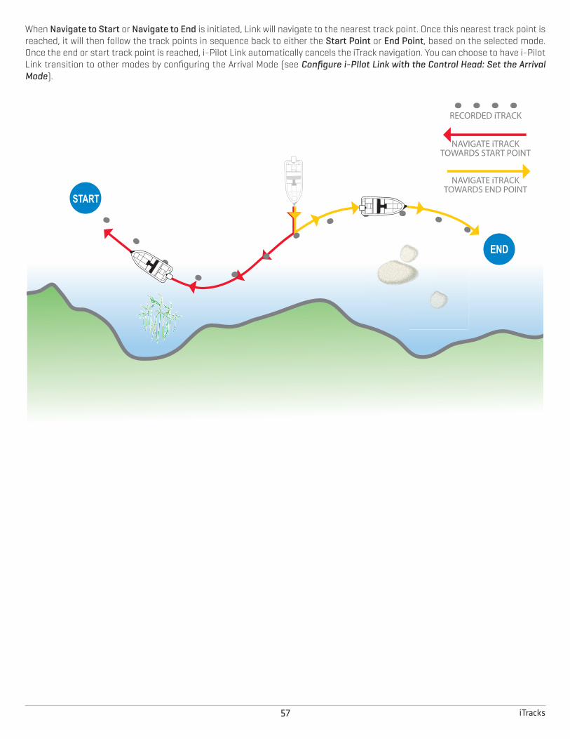
57 iTracks
When Navigate to Start or Navigate to End is initiated, Link will navigate to the nearest track point. Once this nearest track point isreached, it will then follow the track points in sequence back to either the Start Point or End Point, based on the selected mode.Once the end or start track point is reached, i-Pilot Link automatically cancels the iTrack navigation. You can choose to have i-PilotLink transition to other modes by configuring the Arrival Mode (see Configure i-PIlot Link with the Control Head: Set the ArrivalMode).
RECORDED iTRACK
NAVIGATE iTRACKTOWARDS START POINT
NAVIGATE iTRACKTOWARDS END POINT

58iTracks
Record an iTrackWhen Record iTrack is turned on, iTrack recording will begin from the current vessel position, and will automatically stop when a 2mile distance is achieved. The boat must already be moving when iTrack recording is initiated.
Start Recording
1. Press the MARK key.
2. Select Record iTrack. Press the RIGHT Cursor key.
Press the EXIT key until the menu system is closed.
Recording an iTrack
iTrack(magenta line)
iTrack start point
track(red line)
Open theMARK Menu

59 iTracks
Stop Recording1. Press the MARK key.
2. Select Stop Recording iTrack. Press the RIGHT Cursor key.
3. Follow the on-screen prompts to save or discard the iTrack.
Navigate a Saved iTrackIf a saved iTrack is within 1/4 mile of the boat position, you can start navigation towards it. iTrack navigation will start towards thenearest point on the iTrack, and then it will navigate to the Start Point or End Point, depending on your selection.
You can select a saved iTrack on the Chart View or the Go To menu. You can also start navigation to a saved iTrack from the WaypointManagement dialog box (see Manage your i-Pilot Navigation Data).
If you start another mode of i-Pilot Link navigation, iTrack navigation will disengage automatically. The exception is Spot-Lock,which will pause the iTrack navigation.
Networked Control Heads: To share an iTrack on the network or change the iTrack position, you must start navigating the iTrack onthe control head you used to record it.
Navigate a Saved iTrack on the Chart View1. Use the Cursor Control key to select a Start Point icon, an End Point icon, or a position on the iTrack.
2. Press the GO TO key.
3. Select one of the following, and press the RIGHT Cursor key.
To start navigation to the iTrack Start Point, select Navigate to Start.
To start navigation to the iTrack End Point, select Navigate to End.
To navigate to a point within the iTrack, select Go To Position. When you select Go To Position, the i-Pilot Link will navigate tothe cursor position, but it wil not start navigation on the iTrack.
CAUTION! Be prepared for boat movement as the prop will automatically be enabled and the prop speed will automatically adjustto move the boat to the iTrack position. If the boat does not move, confirm the prop is turned on in the menu system (seePropeller Controls).

60iTracks
Navigating a Saved iTrack (Navigate to Start)
navigating to iTrack start point end point

61 iTracks
Navigate to a Saved iTrack from the Go To MenuUse the following instructions to start iTrack navigation from any view.
1. Press the GO TO key.
2. Select Nav Data. Press the RIGHT Cursor key.
3. Select an iTrack to Start or iTrack to End from the Go To list. Press the RIGHT Cursor key.
CAUTION! Be prepared for boat movement as the prop will automatically be enabled and the prop speed will automatically adjustto move the boat to the iTrack position. If the boat does not move, confirm the prop is turned on in the menu system (seePropeller Controls).
Reverse Direction During iTrack NavigationIf you are navigating a saved iTrack, you can quickly change the navigation direction toward the Start Point or End Point. For example,if the i-Pilot Link is navigating to the Start Point, selecting Reverse will start i-Pilot Link navigation in the opposite direction, towardsthe End Point.
1. During navigation on a saved iTrack, press the GO TO key.
2. Select Reverse Navigation. Press the RIGHT Cursor key.
CAUTION! Be prepared for boat movement as the prop will automatically be enabled and the prop speed will automatically adjustto move the boat to the iTrack position. If the boat does not move, confirm the prop is turned on in the menu system (seePropeller Controls).
Cancel Navigation (Disengage) 1. Press the GO TO key.
2. Select Cancel Navigation.
3. Press the RIGHT Cursor key.
Move a Saved iTrackUse the following instructions to move the position of a saved iTrack on the Chart View.
NOTE: If you have more than one networked control head installed, select the control head you used to record the iTrack.
1. Use the Cursor Control key to select a Start Point icon or End Point icon on the iTrack.
2. Press the MENU key.
3. Select the iTrack name. Press the RIGHT Cursor key.
4. Select Move. Press the RIGHT Cursor key.
5. Select Direction or Distance. Press the RIGHT or LEFT Cursor keys to adjust the setting.
As you adjust the setting, an arrow is displayed on-screen to indicate the change.
6. Select Move iTrack. Press the RIGHT Cursor key.

62iTracks
Delete a Saved iTrackYou can delete a saved iTrack in the Chart View or from the Waypoint Management dialog box (see Manage your i-Pilot NavigationData).
1. Use the Cursor Control key to select a Start Point icon or End Point icon on the iTrack.
2. Press the MENU key.
3. Select the iTrack name. Press the RIGHT Cursor key.
4. Select Delete. Press the RIGHT Cursor key.
Moving an iTrack to a New Position
cursor selecting end point saved iTrack
movementdirection
new iTrackposition

63 iTracks
Edit a Saved iTrackWhen you save a iTrack, it is saved with an alphanumeric name that starts with IT. The name can be edited from the Chart View orthe Waypoint Management dialog box (see Manage your i-Pilot Navigation Data).
1. Use the Cursor Control key to select an iTrack Start point or End point in Chart View.
2. Press the MENU key.
3. Select the iTrack name. Press the RIGHT Cursor key.
4. Select Edit. Press the RIGHT Cursor key.
5. Use the Cursor Control key to edit the available fields.
6. Save: Select Save. Press the RIGHT Cursor key.
Show/Hide an iTrack1. Use the Cursor Control key to select an iTrack Start point or End point in Chart View.
2. Press the MENU key.
3. Select the iTrack name. Press the RIGHT Cursor key.
4. Select Edit. Press the RIGHT Cursor key.
5. Select Visibility.
6. Select Visible or Hidden.
Name Select the file name, and press the RIGHT Cursor key.
Visibility To show the iTrack on the Chart View, select Visible. To hide it, select Hidden.
Style Select a line style.
Color Select a color. The Color field is available if you’ve selected a solid line in the Style field.

64BackTrack
BACKTRACKTraditional Humminbird tracks consist of a collection of track points that contain the boat’s detailed position history at set intervals.The Current Track shows the position history since the HELIX control head was powered on. You can clear the Current Track or saveit at any time. For more information about tracks, see your HELIX Operations Manual.
BackTrack starts i-Pilot Link navigation back through the Current Track. When BackTrack is selected, the i-Pilot Link will mark a StartPoint at the boat’s current position and navigate to the last recorded track point. It will then create a saved iTrack on top of theCurrent Track (up to 2 miles).
WARNING! Watch for a turning propeller and be prepared for boat movement when working with iTracks. If Prop Auto On is turnedon, the propeller will automatically turn on when an iTrack is engaged, even if the engagement is accidental. A turning propellercan cause injury.
NOTE: You can activate BackTrack on the Current Track. BackTrack is not available on saved tracks or when Follow the Contouris active.
Adjust the BackTrack DistanceThe control head allows you to BackTrack up to 2 miles. To adjust the distance, use the following instructions.
1. Main Menu: Press the MENU key twice. Select the Accessories tab.
2. Select i-Pilot Settings. Press the RIGHT Cursor key.
3. Select BackTrack Distance.
4. Press the RIGHT or LEFT Cursor keys to adjust the setting.
Start BackTrack NavigationTo use BackTrack, the control head must be actively tracking. Once BackTrack navigation starts, you can also use iTrack features,including Reverse (see the iTracks section for more information).
1. Press the GO TO key.
2. Select BackTrack. Press the RIGHT Cursor key.
CAUTION! Be prepared for boat movement as the prop will automatically be enabled and the prop speed will automatically adjustto move the boat to the iTrack position. If the boat does not move, confirm the prop is turned on in the menu system (seePropeller Controls).
NOTE: If BackTrack is not displayed in the Go To Menu, confirm tracking is enabled (Main Menu > Nav tab > Current Track > StartTracking).
Cancel Navigation (Disengage) 1. Press the GO TO key.
2. Select Cancel Navigation.
3. Press the RIGHT Cursor key.

65 BackTrack
BackTrack Navigation
navigating to end point end point
track(red line)
Open theGo To Menu

66Follow the Contour
FOLLOW THE CONTOURFollow the Contour allows you to navigate a contour on the Chart View. When you start i-Pilot Link navigation to Follow the Contour,all other types of navigation are stopped on the HELIX control head and the Ethernet network. AutoChart Live also allows you to followdepth contours, weed edges, and bottom hardness using the i-Pilot Link.
WARNING! Watch for a turning propeller and be prepared for boat movement when working with Follow the Contour. If Prop AutoOn is turned on, the propeller will automatically turn on when Follow the Contour is engaged, even if the engagement is accidental.A turning propeller can cause injury.
NOTE: When the i-Pilot Link is following the contour, the Current Track is not saved, and iTracks cannot be recorded.
1 | Preparation
Use the following instructions to prepare the control head to Follow the Contour.
Install the Map CardTo use Follow the Contour, an i-Pilot compatible map card must be installed and selected as the map source. If using an AutoChartPCLive Data connection, confirm the connection between your PC and HELIX control head.
Required: i-Pilot Compatible Humminbird LakeMaster Map Card, LakeMaster PLUS Map Card, AutoChart ZeroLine Map Card, orAutoChart Live saved map. Visit humminbird.com for the latest list of compatible charts and accessory guides.
1. Install a compatible map card.
See your control head operations guide for installation details.
2. If the control head does not select the map source automatically, select the Main Menu > Chart tab > Map Source.
Select the installation location of the map card.
WARNING! Do not leave the SD slot cover open. The slot cover should always be closed to prevent water damage to the unit.
Set the Contour Lines to Visible1. Main Menu: Press the MENU key twice. Select the HB Chart tab.
2. Select Contour Lines.
3. Select Visible.

67 Follow the Contour
Set the Water Level Offset Before starting navigation, set the Water Level Offset setting to change the water level read by the HELIX control head. For example,if the lake is down 5 feet, set the Water Level Offset setting to -5. The displayed numbers on the Contour Lines will adjust from theWater Level Offset setting, and the water level offset will be highlighted in brown to extend the land visually on the display.
NOTE: A Humminbird LakeMaster map card must be installed and selected as the map source to enable these features.
1. Main Menu: Press the MENU key twice. Select the HB Chart tab.
2. Select Water Level Offset.
3. Press the RIGHT or LEFT Cursor keys to adjust the setting.
If the water level is higher than normal, set a (+) positive amount.
If the water level is lower than normal, set a (-) negative amount.
If the water level has not changed (normal), set Water Level Offset to (0) zero.
Water Level Offset (Set to 0 = Off) Water Level Offset Adjusted to -4
If the water is lower than normal, set the Water Level Offset to a negativenumber, and the land will extend visually on the map (as shown above). If thewater is higher than normal, set the Water Level Offset to a (+) positive amount,and the water line will extend visually on the map.

68Follow the Contour
2 | Start Follow the Contour Navigation
Follow the ContourYou can start i-Pilot Link navigation if the boat position is within 1/4 mile of the selected contour.
NOTE: If you cannot select a contour because it is displayed under AutoChart Live or Bottom Layer, see Follow Bottom Hardnessor Vegetation: Hide layers.
1. Use the Cursor Control key to select a position on a contour line.
2. Press the GO TO key.
3. Select Follow the Contour. Press the RIGHT Cursor key.
4. Select a navigation direction from the submenu. Press the RIGHT Cursor key.
The navigation direction is previewed in orange or blue on the Chart View.
CAUTION! Be prepared for boat movement as the prop will automatically be enabled and the prop speed will automatically adjustto move the boat to the contour. If the boat does not move, confirm the prop is turned on in the menu system (seePropeller Controls).
Open the GO TO MenuSelect a Contour Line
Selecting a Direction for Follow the Contour
selecteddirection
direction preview
offsetsetting
direction preview

69 Follow the Contour
Reverse Direction 1. During Follow the Contour Navigation, press the GO TO key.
2. Select Reverse Navigation. Press the RIGHT Cursor key.
CAUTION! Be prepared for boat movement as the prop will automatically be enabled and the prop speed will automatically adjustto move the boat to the contour. If the boat does not move, confirm the prop is turned on in the menu system (seePropeller Controls).
Cancel Navigation (Disengage)1. During Follow the Contour Navigation, press the GO TO key.
2. Select Cancel Navigation. Press the RIGHT Cursor key.
Following the Contour
contour distance
selectedcontour
navigationpath(yellow)

70Follow the Contour
Follow an Offset Distance from a ContourYou can set Contour Offset to maintain a set distance from a contour line. Contour Offset is a distance setting only, and does notmeasure water depth. Input the Contour Offset based on your knowledge of the water depth in your current area.
If you have an AutoChart ZeroLine Map Card, and want to navigate along a bank or shoreline, use Contour Offset to maintain a safedistance from the shoreline.
WARNING! Contour Offset does NOT account for changes in water depth. It is important to be aware of depth variations in yourcurrent location and selected navigation route, and adjust the Contour Offset as needed.
1. Use the Cursor Control key to select a position on a contour line.
2. Press the GO TO key.
3. Select Follow the Contour. Press the RIGHT Cursor key.
4. Select Contour Offset.
5. Press the RIGHT or LEFT Cursor keys to set a distance from the contour line.
To remove the offset, set Contour Offset to 0 (zero).
6. Select a navigation direction from the submenu. Press the RIGHT Cursor key.
The navigation direction is previewed in orange or blue on the Chart View.
CAUTION! Be prepared for boat movement as the prop will automatically be enabled and the prop speed will automatically adjustto move the boat to the contour. If the boat does not move, confirm the prop is turned on in the menu system (seePropeller Controls).
Follow Bottom Hardness or VegetationIf you have saved Bottom Layer data (with AutoChart Live) on your control head or installed an AutoChart ZeroLine map card, youcan navigate the selected Bottom Hardness. or Vegetation Layer. The selected starting point must be within 1/4 mile of the selectedbottom layer.
Display Bottom Hardness or VegetationUse the following instructions to display the AutoChart Live bottom layer and type.
1. Chart X-Press Menu: With a Chart View displayed on-screen, press the MENU key once.
2. Select AutoChart Live. Press the RIGHT Cursor key.
3. Select AutoChart Live. Select Visible.
4. Select Bottom Layer. Select Visible.
5. Select Bottom Type.
6. Select Bottom Hardness or Vegetation.
Hide LayersUse the following instructions to hide AutoChart Live Data and Bottom Layer data. You might need to hide these layers to select acontour.
1. Chart X-Press Menu: With a Chart View displayed on-screen, press the MENU key once.
2. Select AutoChart Live. Press the RIGHT Cursor key.
3. Select AutoChart Live. Select Hidden.
4. Select Bottom Layer. Select Hidden.

71 Follow the Contour
Follow Bottom HardnessYou can start i-Pilot Link navigation if the boat position is within 1/4 mile of the selected Bottom Hardness layer.
1. Use the Cursor Control key to select a position on the Bottom Hardness layer.
2. Press the GO TO key.
3. Select Follow Hardness. Press the RIGHT Cursor key.
4. Select a navigation direction from the submenu. Press the RIGHT Cursor key.
The navigation direction is previewed in orange or blue on the Chart View.
CAUTION! Be prepared for boat movement as the prop will automatically be enabled and the prop speed will automatically adjustto move the boat to the bottom hardness layer. If the boat does not move, confirm the prop is turned on in the menu system (seePropeller Controls).
Follow VegetationYou can start i-Pilot Link navigation if the boat position is within 1/4 mile of the selected Vegetation layer.
1. Use the Cursor Control key to select a position on the Vegetation layer.
2. Press the GO TO key.
3. Select Follow Hardness. Press the RIGHT Cursor key.
4. Select a navigation direction from the submenu. Press the RIGHT Cursor key.
The navigation direction is previewed in orange or blue on the Chart View.
CAUTION! Be prepared for boat movement as the prop will automatically be enabled and the prop speed will automatically adjustto move the boat to the vegetation layer. If the boat does not move, confirm the prop is turned on in the menu system (seePropeller Controls).
Reverse Direction 1. During Follow Hardness or Follow Vegetation navigation, press the GO TO key.
2. Select Reverse Navigation. Press the RIGHT Cursor key.
CAUTION! Be prepared for boat movement as the prop will automatically be enabled and the prop speed will automatically adjustto move the boat per the command. If the boat does not move, confirm the prop is turned on in the menu system (seePropeller Controls).
Cancel Navigation (Disengage)1. During Follow Hardness or Follow Vegetation navigation, press the GO TO key.
2. Select Cancel Navigation. Press the RIGHT Cursor key.

72Routes
ROUTESRoutes link two or more waypoints together to create a path for navigation. A route represents your intended navigation and showsthe shortest path from each data point to the next. The distance between each waypoint is a route leg. You can save 47 routes (with50 waypoints each) to the control head.
WARNING! Watch for a turning propeller and be prepared for boat movement when working with routes. If Prop Auto On is turnedon, the propeller will automatically turn on when a route is navigated, even if the engagement is accidental. A turning propellercan cause injury. If the boat does not move, confirm the prop is turned on in the menu system (see Propeller Controls).
Create a Route and Start NavigationUse the instructions in this section to connect waypoints and start navigation immediately.
1. Use the Cursor Control key to move the cursor to a waypoint or position on the chart.
2. Press the GO TO key twice.
3. Repeat steps 1 and 2 to add more waypoints to the route.
Creating and Navigating a Route
next waypoint in the route route start point
Press Twice to StartNavigationMove the Cursor
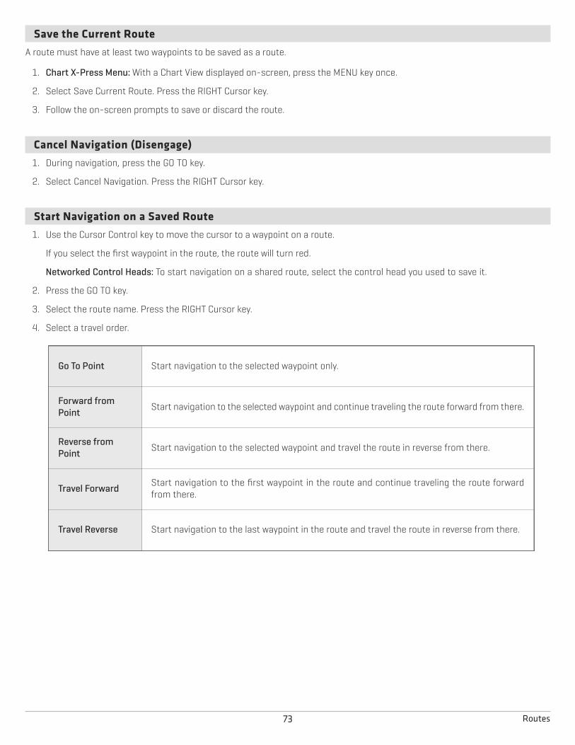
73 Routes
Save the Current RouteA route must have at least two waypoints to be saved as a route.
1. Chart X-Press Menu: With a Chart View displayed on-screen, press the MENU key once.
2. Select Save Current Route. Press the RIGHT Cursor key.
3. Follow the on-screen prompts to save or discard the route.
Cancel Navigation (Disengage)1. During navigation, press the GO TO key.
2. Select Cancel Navigation. Press the RIGHT Cursor key.
Start Navigation on a Saved Route1. Use the Cursor Control key to move the cursor to a waypoint on a route.
If you select the first waypoint in the route, the route will turn red.
Networked Control Heads: To start navigation on a shared route, select the control head you used to save it.
2. Press the GO TO key.
3. Select the route name. Press the RIGHT Cursor key.
4. Select a travel order.
Go To Point Start navigation to the selected waypoint only.
Forward fromPoint Start navigation to the selected waypoint and continue traveling the route forward from there.
Reverse fromPoint Start navigation to the selected waypoint and travel the route in reverse from there.
Travel Forward Start navigation to the first waypoint in the route and continue traveling the route forwardfrom there.
Travel Reverse Start navigation to the last waypoint in the route and travel the route in reverse from there.

74Routes
Edit a Saved RouteWhen you save a route, it is saved with an alphanumeric name that starts with RT. The name can be edited from the Chart View orthe Waypoint Management dialog box (see Manage your i-Pilot Navigation Data).
1. Use the Cursor Control key to move the cursor to a waypoint on the route. Press the MENU key.
OR
If the route was saved recently, you don’t have to select it first. Press the MENU key.
2. Select the route name. Press the RIGHT Cursor key.
3. Select Edit. Press the RIGHT Cursor key.
4. Use the Cursor Control key to change the route name.
Visibility: Select Visible or Hidden.
5. Save: Select Save. Press the RIGHT Cursor key.
Show/Hide a Route1. Use the Cursor Control key to move the cursor to a waypoint on the route. Press the MENU key.
OR
If the route was saved recently, you don’t have to select it first. Press the MENU key.
2. Select the route name. Press the RIGHT Cursor key.
3. Select Edit. Press the RIGHT Cursor key.
4. Select Visibility.
5. Select Visible or Hidden.
6. Save: Select Save. Press the RIGHT Cursor key.

75 AutoPilot
AUTOPILOTWhen in AutoPilot, i-Pilot Link keeps the trolling motor pointed in the direction you want to go. Each time the wind or water currentmoves the boat off course, AutoPilot senses the change and steers itself back to the original heading. The AutoPilot direction is setevery time a steering change is made. AutoPilot will pull the bow of the boat around and correct automatically until the boat ismoving in the direction you chose.
AutoPilot is available in Advanced or Legacy mode. Both modes are valuable tools for accurate and precise bait presentation. Wehighly recommend trying both Advanced AutoPilot and Legacy AutoPilot in various fishing situations and applications. Withexperimentation and time you will find which AutoPilot Mode works best for you in any given situation.

76AutoPilot
Advanced AutoPilotAdvanced AutoPilot not only uses compass heading but also GPS data to correct for cross winds, current and other external forcesto keep the boat on the intended course. When Advanced AutoPilot is turned on, it creates a course that it will follow. When you steerto a new heading, a new course is created. Advanced AutoPilot will keep the boat on the course in most conditions. When veryextreme conditions exist, such as very strong winds or current, the trolling motor may not have enough power to control the boatsmoothly. In these extreme cases it may be best to use Legacy AutoPilot and let the boat move with the wind or current if the motoris not powerful enough to overcome it.

77 AutoPilot
Legacy AutoPilotLegacy AutoPilot uses an internal compass to provide heading lock. When Legacy AutoPilot is on, it keeps the motor pointed in thesame compass direction. If a manual steering correction is made, Legacy AutoPilot locks onto the new compass heading to whichthe boat was steered. This method of heading tracking does not take into account external forces, such as side winds or currents,which can allow side drift.

78AutoPilot
AutoPilot OverviewYou can start AutoPilot navigation based on the motor heading or the cursor position. Also, AutoPilot can be used with Cruise Controland while recording an iTrack. If another mode of navigation that controls steering is enabled while AutoPilot is enabled, AutoPilotwill disable automatically.
WARNING! It is the operator’s responsibility to make prudent decisions regarding personal safety and the operation of the vessel.Do NOT leave the autopilot unattended while it is steering the vessel. Watch for obstacles and potential hazards at all times. Beprepared to respond to changing conditions and take manual control of the vessel as required.
WARNING! Do NOT use the autopilot where there may be shallow water, obstacles, or when manual navigation is required,especially in the following situations:
• while navigating or maneuvering in shallow waters or dangerous seabeds,
• while entering or exiting harbor, mooring, or setting sail,
• while traveling at high speed,
• in heavy traffic areas, near breakwaters, canals,
• or while encountering any potential obstacles.
WARNING! Watch for a turning propeller and be prepared for boat movement when working with AutoPilot. If Prop Auto On isturned on, the propeller will automatically turn on when AutoPilot is engaged, even if the engagement is accidental. A turningpropeller can cause injury. If the boat does not move, confirm the prop is turned on in the menu system (see Propeller Controls).
WARNING! To cancel AutoPilot navigation, you must select Cancel Navigation and then turn the propeller off. The propeller doesnot automatically turn off when navigation is canceled. See Cancel Navigation and Propeller Controls for more details.
CAUTION! The i-Pilot Link uses a magnetic compass to detect direction of travel. The compass can be adversely affected bymagnets or large, ferrous metal objects near (within 24” of) the trolling motor control head.
Obstructions on the propeller may cause excessive vibration of the motor head. This vibration can cause the compass to wanderand erratic steering to occur. Clear the obstruction to return the motor to normal operation. See the i-Pilot Link Owner’s Manualfor details.
NOTE: When AutoPilot is on and the trolling motor is pulled out of the water to the stow position, the steering motor will continueto run. Turn off AutoPilot to stop the motor. If AutoPilot is left on, the steering motor will shut off automatically after 8 seconds.The motor should not be stored in this condition for long periods as power is still being applied to all electronics. Always turnAutoPilot off and disconnect your motor from the battery when storing your motor. See the i-Pilot Link Owner’s Manual fordetails.
Start AutoPilot NavigationYou can start AutoPilot navigation based on the motor heading or the cursor position.
CAUTION! Be prepared for boat movement as the prop will automatically be enabled and the prop speed will automatically adjustto move the boat to the waypoint position. If the boat does not move, confirm the prop is turned on in the menu system (seePropeller Controls).
Select the AutoPilot Mode1. Main Menu: Press the MENU key twice. Select the Accessories tab.
2. Select i-Pilot Settings. Press the RIGHT Cursor key.
3. Select AutoPilot Mode.
4. Select Legacy or Advanced.

79 AutoPilot
Start AutoPilot Based on the Motor’s HeadingWhen you start AutoPilot navigation without the cursor, the heading is based on the trolling motor’s heading. AutoPilot continuesto navigate the boat in the same direction.
1. Press the GO TO key.
2. Select AutoPilot. Press the RIGHT Cursor key.
Start AutoPilot Towards the Cursor PositionUse the cursor to set the heading for AutoPilot navigation. i-Pilot Link will start navigation and maintain a constant heading towardsthe cursor position.
1. Use the Cursor Control key to move the cursor to a position on the chart.
2. Press the GO TO key.
3. Select AutoPilot. Press the RIGHT Cursor key.
AutoPilot Navigation to the Cursor Position
advanced AutoPilot mode
Open theGO TO MenuMove the Cursor
track (red line)
boatheading(greenline)
autopilotheading(purple line)

80AutoPilot
Adjust the HeadingUse the i-Pilot X-Press Remote to adjust the heading during AutoPilot navigation.
NOTE: After steering to a new direction, there is a short delay before the direction is locked in to allow the compass to stabilize.When broad speed changes are made, the motor heading may change slightly. This is normal.
CAUTION! Be prepared for boat movement as the prop will automatically be enabled and the prop speed will automatically adjustto move the boat to the waypoint position. If the boat does not move, confirm the prop is turned on in the menu system (seePropeller Controls).
Adjust the AutoPilot Heading1. Press the POWER key.
2. Confirm the Steer/Prop menu is selected.
3. Press the RIGHT or LEFT Cursor keys.
Changing the Heading
propeller On
Open Steer

81 AutoPilot
Show/Hide the AutoPilot Heading Line1. Main Menu: Press the MENU key twice. Select the Accessories tab.
2. Select i-Pilot Settings. Press the RIGHT Cursor key.
3. Select AutoPilot Heading Line.
4. Select On or Off.
Cancel Navigation1. Press the GO TO key.
2. Select Cancel Navigation.
3. Press the RIGHT Cursor key.
4. Press the POWER key.
5. Select Prop > Off.
WARNING! To cancel AutoPilot navigation, you must select Cancel Navigation and then turn the propeller off. The propeller doesnot automatically turn off when navigation is canceled. See Propeller Controls for more details.

82Navigation Data
MANAGE YOUR i-PILOT LINK NAVIGATION DATAYou can edit iTracks and Spot-Locks using the Waypoint Management dialog box in the same way that you can edit otherHumminbird navigation data. You can also create new iTracks and Spot-Locks, and you can start navigation to the selected item.
The features that are unique to i-Pilot Link are described in this section. For more details about the Waypoint Management dialogbox, see your HELIX Operations Manual.
Overview
Open the Waypoint Management Dialog Box1. Main Menu: Press the MENU key twice. Select the Nav tab.
2. Select Waypoints, Routes, Tracks.
3. Press the RIGHT Cursor key.
SortYou can sort your saved navigation data alphabetically or by newest/oldest date, distance, or icon.
1. Press the EXIT key.
2. Select Sort By.
3. Press the RIGHT or LEFT Cursor keys to select a sort setting.
Select a FileUse these instructions to select an individual waypoint, route, track, or group. Then, use the submenu to apply settings or actionsto the selected file.
1. Press the DOWN or UP Cursor keys to select a saved waypoint, route, track, iTrack, Spot-Lock, or group.
2. Open the Submenu: Press the RIGHT Cursor key.

83 Navigation Data
Open a Menu Go BackScroll through the List
Selecting Files in the Waypoint Management Dialog Box (Waypoints, Routes, Tracks)
selected group
information andinstructions
track
iTrackroute
Spot-Lock(selected file)
selected filepreview
waypoint

84Navigation Data
Jump to the TopThe Options menu, and other important actions, are located at the top of the Waypoint Management dialog box. Use theseinstructions to quickly select Options or jump to the top.
1. Press the EXIT key.
Selecting Options (Jump to the Top)
Directory: Bass08 isthe selected group
information
Options
Jump to the Top Open a Menu

85 Navigation Data
Open the Spot-Lock SubmenuYou can use the Waypoint Management dialog box to edit a saved Spot-Lock or start navigation modes. Also, see the Spot-Locksection for more information.
Open the Spot-Lock Submenu1. Select a Spot-Lock from the Waypoint Management dialog box. Press the RIGHT Cursor key.
2. Select one of the following menu options:
Edit Opens the Edit Spot-Lock menu.
Delete Deletes the Spot-Lock. To remove the Spot-Lock from the group, choose Selected. To deletethe Spot-Lock from all groups, choose All Instances.
Duplicate Creates a copy of the Spot-Lock and adds it to a new group or route.
Save As Creates a Spot-Lock (based on the selected Spot-Lock) and opens a menu so you can changethe new Spot-Lock’s name.
Move Moves the Spot-Lock from the selected group to a different group.
Cursor To Moves the cursor to the selected Spot-Lock in the Chart View.
Go To Starts navigation to the selected Spot-Lock.
Spot-Lock Starts Spot-Lock navigation at the selected Spot-Lock.
Circle Starts Circle mode navigation around the selected Spot-Lock position. See the Circle Modesection for details.
Target Displays a target on the selected Spot-Lock in the Chart View.
Grid Displays a grid on the selected Spot-Lock in the Chart View.

86Navigation Data
Open the iTrack SubmenuYou can use the Waypoint Management dialog box to edit a saved iTrack or start navigation modes. Also, see the iTrack section formore information.
Open the iTrack Submenu1. Select an iTrack from the Waypoint Management dialog box. Press the RIGHT Cursor key.
2. Select one of the following menu options:
Edit Opens the Edit iTrack menu.
Navigate to Start Starts navigation to the iTrack start point.
Navigate to End Starts navigation to the iTrack end point.
Delete Deletes the iTrack. To remove the iTrack from the group, choose Selected. To delete the iTrackfrom all groups, choose All Instances.
Duplicate Creates a copy of the iTrack and adds it to a new group or route.
Move Moves the waypoint from the selected group to a different group (see the iTracks section fordetails).
Info Displays latitude/longitude information, iTrack distance, creation date, and point information.

87 Navigation Data
Export Nav DataUse the following instructions to export your navigation data to an SD card or microSD card. To export saved iTracks andSpot-Locks to the i-Pilot Link, see Configure i-PIlot Link with the Control Head: Turn on Auto Upload Data.
WARNING! Humminbird is not responsible for the loss of data files (waypoints, routes, tracks, groups, recordings, etc.) that mayoccur due to direct or indirect damage to the unit’s hardware or software. It is important to back up your control head’s data filesperiodically. Data files should also be saved to your PC before restoring the unit’s defaults or updating the software. See yourHELIX Operations Manual for details.
NOTE: Do not leave the SD card slot cover open. The slot cover should always be closed to prevent water damage to the unit.
Export ALL Navigation ItemsExport your navigation items to an unlocked, installed microSD or SD card (separate purchase required). See your HELX OperationsManual for compatibility details.
1. Install the SD card or microSD card according to the instructions in your control head operations manual.
2. Open the Waypoint Management dialog box.
3. Select Options > Select All and... > Export.
4. Follow the on-screen prompts to confirm or cancel the export.
Export Selected Navigation ItemsYou can also select individual navigation items and export them to an unlocked, installed microSD or SD card. See your HELIXOperations Manual for compatibility details.
1. Install the SD card or microSD card according to the instructions in your control head operations manual.
2. Open the Waypoint Management dialog box.
3. From a selected group, select Options > Select Multiple and... > Export.
4. Select Items: Press the UP or DOWN Cursor keys to scroll through the waypoints, routes, and tracks. Press the RIGHT Cursorkey to select an item. Repeat as needed.
5. Confirm Export: Press the EXIT key to select Export Selected.
Press the RIGHT Cursor key. Follow the on-screen prompts to confirm or cancel the export.

88Contact Humminbird
CONTACT HUMMINBIRDContact Humminbird Customer Service in any of the following ways:
Web site:
humminbird.com
E-mail:
Telephone:
1-800-633-1468
Direct Shipping:
HumminbirdService Department678 Humminbird LaneEufaula, AL 36027 USA
Hours of Operation:
Monday - Friday
8:00 a.m. to 4:30 p.m. (Central Standard Time)
Social Media Resources:
Facebook.com/HumminbirdElectronics
Twitter.com (@humminbirdfish)
YouTube.com/humminbirdtv


