I1 Ill Ill1 I II II I 3 4456 0134L48 8 ORNL-3500 UC-25 - Metals, Ceramics, and Materials TID-4500 (23rd ed.) FABRICATION OF THE HEAT EXCHANGER TUBE BUNDLE FOR THE MOLTEN-SALT REACTOR EXPERIMENT R. G. Donnelly G. M. Slaughter - OAK RIDGE NATIONAL LABORATORY operated by UNION CARBIDE CORPORATION for the U.S. ATOMIC ENERGY COMMISSION
Transcript
I1 I l l Ill1 I I I I I I 3 4 4 5 6 0 1 3 4 L 4 8 8
ORNL-3500 UC-25 - Metals, Ceramics, and Materials
TID-4500 (23rd ed.)
FABRICATION OF THE HEAT EXCHANGER
TUBE BUNDLE FOR THE MOLTEN-SALT
REACTOR EXPERIMENT
R. G. Donnelly G. M. Slaughter
-
O A K RIDGE NATIONAL LABORATORY operated by
U N I O N CARBIDE CORPORATION for t h e
U.S. ATOMIC ENERGY COMMISSION
LEGAL NOTICE
T h i s report was prepared o s an account of Government sponsored work. Neither the United States,
nor the Commission, nor any person acting on behalf o f the Commission:
A. Makes any warranty or representotion, expressed or implied, w i th respect t o the accuracy,
completeness, or usefulness of the information contoined i n th i s report, or that the use of
any information, apparatus, method, or process d isc losed i n th i s report may not infr inge
pr ivote ly owned r ights; or
B. Assumes any l i a b i l i t i e s w i th respect t o the use of, or for domagee resul t ing from the use of
any information, opporotus, method, or process d isc losed in th i s report.
As used in the above, "person acting on behalf of the Commission" inc ludes any employee or
contractor of the Commission. or employee of such controctor, t o the extent that such employee
or contractor o f the Commission, or employee of such contractor prepares, disseminates, or
provides access to, any information pursuant t o h i s employment or controct w i t h the Commission,
or h i s employment w i th such contractor.
.
ORNL-3500
Contract No. W-7405-eng-26
ME;TALS AND CERAMICS DIVISION
FABRICATION OF THE HEAT EXCHANGER TUBE BUNDLE FOR THE MOLTEN-SALT REACTOR EXPERIMENT
R. G. Donnelly and G. M. Slaughter
OAK R I E E NATIONAL LABORATORY Oak Ridge, Tennessee
t
iii
TABU OF CONTENTS
ABSTRACT ....................................................... INTROEUCTION ................................................... J O I N T DESIGN ................................................... PRELIMINARY INVESTIGATIONS .....................................
Alloy Selection .......................................... Technique Development ....................................
FABRICATION OF MOCKUP SAMPLES .................................. Small Sample ................................................ Large Sample ................................................
FABRICATION OF MSRE FEAT EXCHANGER TUBE BUNDL9 ................. Welding and Brazing ......................................... Inspection ..................................................
S W Y ........................................................ ACKNOWLEDGMENT .................................................
v
1
1
6
6
7 7 10
12
12
15
17 17 26
31
31
.
FABRICATION OF THE HEAT EXCHANGER TUBE BUNDIX
FOR THE MOLTEN-SALT REACTOR EXPERIMENT
R. G. Donnelly and G. M. Slaughter
ABSTRACT
the Molten-Salt Reactor Experiment contains 163 1/2-in. diam x 0.042-in. -wall U-tubes welded t o a 1 1/2-in. - thick tube sheet, 17 in . i n diameter. Procedures were successfully developed f o r welding and back brazing the closely spaced 326 tube-to-tube sheet j o i n t s i n the uni t , and the ac tua l tube bundle was fabricated without incident . provides a double s e a l between the f u e l and coolant s a l t s and was used because of the necessi ty f o r high j o i n t i n t eg r i ty .
The INOR-8 tube bundle of t h e primary heat exchanger of
The welded and back-brazed design
Trepan grooves were machined i n the weld s ide of the tube sheet so t h a t low-restraint edge-type welds could be made. This technique g rea t ly reduces the cracking problems associated with welding thin-walled tubes t o th i ck tube sheets. Welding and assembling procedures were developed which provided welds of high qua l i ty with a minimum of rol l -over .
The 82 Au-18 N i ( w t $) brazing a l loy used i n t h i s
A appl icat ion i s corrosion r e s i s t an t , duc t i le , and produces j o i n t s exhibi t ing sa t i s f ac to ry mechanical s t rength, unique j o i n t design inco rpxa t ing a trepan groove and feeder holes was used f o r the braze s ide, the purpose being t o pre- vent p re fe ren t i a l flow of a l loy on the r e l a t i v e l y thin-walled tubes .
After the determination of exact welding and brazing conditions on severa l subsize and f u l l - s i z e mockup samples, the ac tua l u n i t w a s constructed. Nondestructive inspection of the welds revealed no defects . Good general f l o w of the brazing a l loy w a s evident, and u l t rasonic examination of brazed j o i n t s showed only minor sca t te red porosity. The com- pleted u n i t passed both helium-leak and 800-psi hydrostat ic t e s t s .
.
INTRODUCTION
The Molten-Salt Reactor Experiment i s fueled with a molten s a l t
consisting of LiF, BeF2, ZrF4, and UF4. This fuel-bearing f l u i d i s
pumped through the reactor , fuel-circulat ing pump, and the s h e l l s ide
of the primary heat exchanger.
LiF-BeF2, c i rcu la tes through the tube s ide of the heat exchanger and an
air-cooled radiator .
A nonfuel-bearing coolant s a l t ,
The containment mater ia l i s the commercially avai lable a l loy,
INOR-8 (Ni -17 Mo-7 Cr-4 Fe, w t $). high-strength mater ia l which possesses excel lent corrosion resis tance
t o the molten s a l t s and good oxidation resis tance. It also exhibi ts
good general weldabili ty.
This a l loy i s a nonage-hardenable
I n view of the general d i f f i c u l t i e s associated with repa i r or
replacement of a radioact ively contaminated heat exchanger, an extensive
program was conducted t o develop fabr ica t ion procedures which would
ensure a very high degree of r e l i a b i l i t y . This report describes the
development of the combination welded and back-brazed tube-to-header
j o i n t used f o r t h i s component and the spec i f i c d e t a i l s of the procedure
used i n fabr ica t ing it. The heat exchanger i s of the conventional U-tube design with the
tubes being 0.5-in. OD x 0.042-in. w a l l . All tube ends are joined t o a
1 1/2-in.-thick INOR-8 tube sheet, 17 i n . i n diameter, as shown i n
Fig. 1. Design data f o r the un i t are presented i n Table 1.
JOINT DESIGN
The conventional welded tube-to-header j o i n t has performed satis- f a c t o r i l y i n a very large percentage of heat exchanger applications a t
'MSRP Quart. Progr. Rept. July 31, 1960, ORNL-3014, p 3.
3G. M. Slaughter, P. Pa t r imca , and R. E. Clausing, Welding J. 38(10), 393~400s (1959).
2
112-in-OD TUBES, /A
THERMAL-BARRIER PLATE
COOLANT I N L E T
36 4 - in OD x 0 2 - i n WALL x 8-11 LONG 9,-
UNCLASSIFIED ORNL-LR-CWG 52036R2
FUEL INLET
NT OUTLET COOLA n COOLANT-STREAM / SEPARATING BAFFLE
FUEL OUTLET
Fig. 1. Heat Exchanger f o r MSRE.
3 . Table 1. Primary Heat Exchanger Design Data
St ruc tura l material
Heat load ( M w )
Shell-side f l u i d
TJbe-side f l u i d
Layout
Baffle p i t ch ( in . )
Tube p i tch ( i n . )
Tube
Outside diameter ( in . ) Wall thickness ( in . )
Active s h e l l length ( f t )
Average tube length ( f t )
Number of U-tubes
Shel l diameter ( in . ) Overall length ( f t )
Tube-sheet thickness ( in . )
Design temperature (OF)
Design pressure
Shel l (psig)
Tube (psig)
Terminal temperatures
Fuel sa l t (OF)
Coolant s a l t (OF)
Exchanger geometry
Effect ive log mean temperature
Active heat- t ransfer surface
Fuel-sal t holdup ( f t3 )
Pressure drop
difference ( OF)
area ( f t 2 )
Shel l side (psig)
Tube s ide (psig)
INOR-8
10
Fuel s a l t
Coolant s a l t
25% Cut, cross-baffled s h e l l
12
0.775
and U-tube
0.5
0.042
6
Approximately 14 163
16
Approximately 8 1 1/2
1300
75 125
I n l e t 1225; o u t l e t 1175 I n l e t 1025; o u t l e t 1100
Parallel-counter flow
133
25 9
6.1
24 29
4
4 low and intermediate temperatures. However, as has been reported,
j o i n t s of t h i s type, although i n i t i a l l y sound, a re subject t o cracking
during cyc l ic service a t high temperatures.
program i n which heat exchanger camponents were subjected t o very severe
steady-state and cyclic-temperature service w a s terminated prematurely
as a r e s u l t of t he f a i l u r e of severa l tube-to-tube sheet j o i n t s . Since
no microfissures had been observed during the metallographic examination
of a large number of as-velded jo in t s , it was concluded t h a t t he i n i t i a -
t i o n and propagation of the cracks occurred during thermal cycling.
appeared t h a t these cracks or iginated a t the unavoidable notch a t the
root of t he weld.
A performanc? t e s t i n g
It
One means f o r circumventing t h i s problem i s t o back braze and The loca t ion of the major s t r e s s i s thereby eliminate the notch.5
removed from the weld and relocated t o a more favorable area near t he
braze f i l l e t . Back brazing a l so provides supplementary functions i n
t h a t it reinforces welds containing undetected flaws.
The welded and back-brazed j o i n t design chosen f o r t h i s appl icat ion
i s shown schematically i n Fig. 2. The weld j o i n t makes use of trepan
grooving i n the tube sheet so t h a t low-restraint edge-type welds can be
used. This, i n e f f ec t , g rea t ly reduces cracking problems associated
with welding thin-walled tubes t o th ick tube sheets.
The back-braze j o i n t d e t a i l i s s imi la r t o t h a t on the weld s ide,
except t h a t it contains three feeder holes and a wider trepan groove
t o accept the brazing al loy.6 eliminate the problem of p re fe ren t i a l runoff of the brazing a l loy onto
the thin-walled tube which tends t o reach brazing temperature before
the heavy tube sheet . With t h i s design, the a l loy cannot m e l t or flow
u n t i l the tube sheet has reached brazing temperature; a t t h i s time, t he
a l loy flows down the feeder holes and along the j o i n t . Since the a l loy
The trepan design was used here t o
4p. Pa t r ia rca , G. M. Slaughter, and W. D. Manly, Welding J. - 36(12), 1172-78 ( D ~ c . 1957). -
5G. M. Slaughter and P. Patr iarca, Welding and Brazing of High- Temperature Radiators and Heat Exchangers, ORNL-TM-147 (Feb. 20, 1962).
6P. Patr iarca, C. E. Shubert, and G. M. Slaughter, "Method of Making a Tube and P la t e Connection," U. S. Patent No. 3,078,551 (Feb. 26, 1963).
5
UNCLASSIFIED ORNL-LR-DWG 65682R3
TUBE TREPAN GROOVE WITH BRAZING ALLOY RING
WELD SIDE’ \TREPAN
( a ) BEFORE WELDING AND BRAZING
( b ) AFTER WELDING AND BRAZING
Fig. 2. Schematic Drawing of Welded and Back-Brazed J o i n t Design.
6
does not flow out of the groove, the observation of a braze f i l l e t
around the tube serves as a b u i l t - i n inspection technique since it assures t h a t t he a l loy has been i n the j o i n t and flowed up the j o i n t
by c a p i l l a r i t y ,
brazing a l loy from one j o i n t t o another, thereby ensuring t h a t each
j o i n t has a su f f i c i en t amount of a l loy.
The trepan design a l so eliminates "swapping" of
PRELIM1E;IARY INVESTIGATIONS
Welding
An experimental study w a s conducted t o develop sa t i s f ac to ry con-
d i t ions for making high qua l i ty tube-to-tube sheet welds. The desired features of the welds were:
(T = tube wal l thickness of 0.042 i n . ) , (2) no surface imperfections,
(3) no porosity, and ( 4 ) no cracks.
was a l so i n s t i t u t e d i n order t o allow passage of a probe f o r u l t rasonic
inspection of t he brazed jo in t s .
(1) a minimum of 1-T penetration
A minimum "roll-over" requirement
Porosity could be readi ly eliminated by carefu l cleaning of the
tubes and tube sheet. They were scrubbed with both t r ichlorethylene
and acetone, and subsequently assembled with clean white gloves.
Root cracking w a s e f f ec t ive ly eliminated by providing a very t i g h t
f i t - u p between the tube and tube sheet . This w a s obtained by f l a r i n g
the j o i n t on the weld s ide of t he tube sheet t o a m a x i m u m depth of
1/8 in . j o i n t was f l a r e d t o a 0.530-in. I D with a spec ia l punch and (2) the tube end w a s extended through the tube sheet and f l a r e d t o a
0.532-in. OD with a similar punch. With a 0.002-in. interference f i t ,
the tube end had t o be tapped l e v e l with the tube sheet surface f o r
welding. This procedure ensured a very snug f i t of the tube and tube
sheet a t the weld area.
The procedure w a s as follows: (1) the tube sheet pa r t of the
The welding parameters ( i . e . , current, t r a v e l speed, a r c distance,
e t c . ) were adjusted t o provide the desired 1-T minimum penetrat ion
withoat excessive rol l -over .
t o provide consis tent ly sound welds and allow sa t i s f ac to ry operator
control. Samples were made a t various welding currents and the depth
of penetration and amount of rol l -over noted. The welding conditions
f i n a l l y selected f o r use on the MSRE heat exchanger are l i s t e d i n Table 2.
A t r a v e l speed of 7.3 in./min w a s found
7
Table 2. Welding Conditions f o r MSRE Tube-to-Tube Sheet Jo in t s
Electrode mater ia l
Electrode diameter
Electrode taper
Ele c t rode - to -work d i stance
Electrode pos i t ion
Ine r t gas
Gas flow r a t e
Welding amperage
Electrode t r a v e l speed
Weld overlap ( fu l l amperage)
Weld overlap (amperage taper)
Welding posi t ion
Tungsten plus 2$ t ho r i a
3/32 in .
30-deg included angle
0.035 i n , (determined by f e e l e r
0.005-in. outside j o i n t in te r face gage )
f o r f u l l 360-deg ro ta t ion ( f 0.002-in. concentric)
Argon ( 99.995 5 pur i ty)
12-13 cfh
3%0
7.3 in./min
3 M O deg
120-150 deg
F l a t
Brazing
Alloy Selection
The 82 Au-18 N i ( w t $) brazing a l loy was chosen f o r t h i s study
because of i t s generally good brazing charac te r i s t ics on INOR-8 i n dry
hydrogen, i t s sa t i s f ac to ry corrosion resis tance t o molten f luoride
salts ,7 i t a good d u c t i l i t y , and i t s r e l a t i v e l y low brazing temperature
(1830°F, which i s below the r ec rys t a l l i za t ion temperature of INOR-8) . In order t o obtain s t rength information on t h i s type of j o in t ,
Miller-Peaslee-type shear- tes t specimens,8 as shown i n Figs. 3 and 4,
were furnace brazed and t e s t ed a t room temperature and a t the reactor
operating temperature of 1300°F.
i n Table 3.
The results of these t e s t s are l i s t e d
7E. E. Hoffman -- e t a l . , An Evaluation of the Corrosion and Oxidation h-Temperature Brazing Alloys, ORNL-1934, p 16
8F. M. Miller and R. L. Peaslee, Welding J. - 37(4) , 144s-50~ I (April 1958).
8
UNCLASSIFIED ORNL-LR-DWG 78478
7 + in. DIA
\ 5 in. R min 16
,-& t& in. R
-1 k 0 . 1 2 5 in. BRAZED JOINT LENGTH
MACH IN E
F i g . 3 M i ller -Pea slee -Type She ar -Te s t Spe cimen . .
t 8 I 4
UNCLASSlFl ED Y.44199 . . .
Testing Temperature 1 3 0 0 ° F
Testing Temperature R. T.
Fig. 4. Typical Miller-Peaslee-Type Shear-Test Specimens. Note the clean shear at the brazed joint on the specimen tested at 1300°F and the elongated and rotated joint on the specimen tested at room temperature. In both cases, separation was in the brazed joint.
10
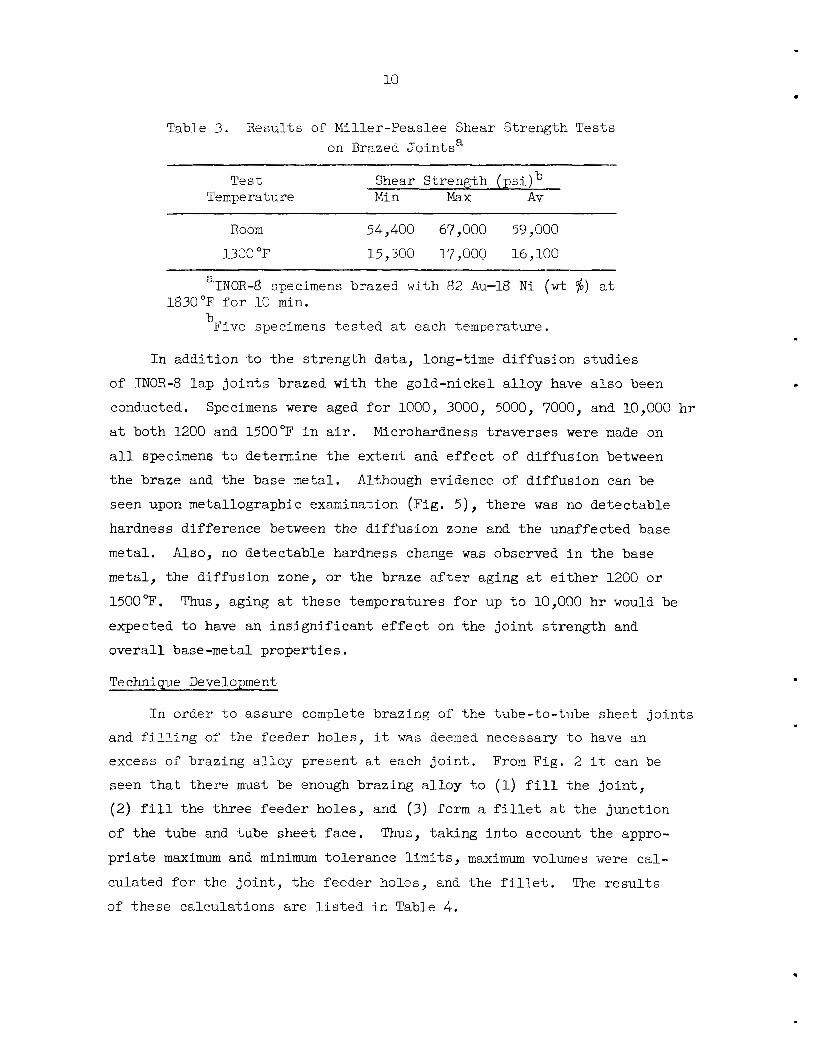
Table 3. Results of Miller-Peaslee Shear Strength Tests on Brazed Jo in tsa
Test Shear Strength (ps i ) Temperature Min Max AV
INOR-8 specimens brazed with 82 Au-18 N i (wt $) a t a
1830°F f o r 10 min.
bFive specimens t e s t ed a t each temperature.
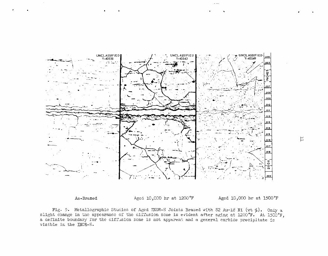
In addition t o the s t rength data, long-time diffusion s tudies
of INOR-8 l a p j o i n t s brazed with the gold-nickel a l loy have a l so been
conducted.
a t both 1200 and 1500°F i n a i r . Microhardness t raverses were made on
a l l specimens t o determine the extent and e f f e c t of diffusion between
the braze and the base metal.
seen upon metallographic examination (Fig. 5) , there w a s no detectable
hardness difference between the diffusion zone and the unaffected base
metal.
metal, the diffusion zone, o r the braze a f t e r aging a t e i t h e r 1200 o r
1500'F.
expected t o have an ins igni f icant e f f e c t on the j o i n t s t rength and
overa l l base-metal propert ies .
Specimens were aged f o r 1000, 3000, 5000, 7000, and 10,000 h r
Although evidence of d i f fus ion can be
Also, no detectable hardness change was observed i n the base
Thus, aging a t these temperatures f o r up t o 10,Oc10 h r would be
Technique Development
In order t o assure complete brazing of the tube-to-tube sheet j o in t s and f i l l i n g of the feeder holes, it was deemed necessary t o have an excess of brazing a l loy present a t each j o i n t . From Fig. 2 it can be
seen t h a t there must be enough brazing a l loy t o (1) f i l l the jo in t , (2) f i l l the three feeder holes, and (3) form a f i l l e t a t the junction
of the tube and tube sheet face. Thus, taking in to account the appro-
p r i a t e m a x i m u m and minimum tolerance l i m i t s , maximum volumes were cal-
culated f o r the j o i n t , the feeder holes, and the f i l l e t .
of these calculations a re l i s t e d i n Table 4. The r e su l t s
I 4
A s -Brazed Aged 10,000 hr a t 1200 "F Aged 10,000 hr a t 1500°F
Fig. 5. Metallographic Studies of Aged INOR-8 Jo in t s Brazed with 82 Awl8 N i ( w t $) . Only a s l i g h t change i n the appearance of the d i f fus ion zone i s evident a f t e r aging a t 1200°F. a de f in i t e boundary for the diffusion zone i s not apparent and a general carbide prec ip i ta te i s v i s i b l e i n the INOR-8.
A t 1500"F,
12
Table 4. Summary of Volume Calculations
. ~~ ~~
3
3 Maximum F i l l e t Volme 0.7 x i n . M a x i m u m J o i n t Volume 7.1 X lo'' i n .
Maximum 3'eeder Hole Volume ( t o t a l of th ree holes)
3 4.2 x 10'' i n .
Maximum Total Volume t o be F i l l e d with Alloy 12.0 x 10'~ in . 3
Volume of One S p l i t Alloy Ring (3/32-in. diam)
3 13.8 X i n .
Wire preforms, 3/32 in . i n diameter, were found t o provide an
adequate supply of alloy,and the necessary s i ze of trepan could be
machined around each j o i n t without encroaching on a neighbor.
Consequently, one 3/32-in. s p l i t r ing was positioned i n each trepan
groove before assembly with the tubes. re ta ined i n the grooves by upsett ing the edges of t he tsbe sheet face
around the outside of the trepans with a spec ia l machinist 's punch.
The r ings were pos i t ive ly
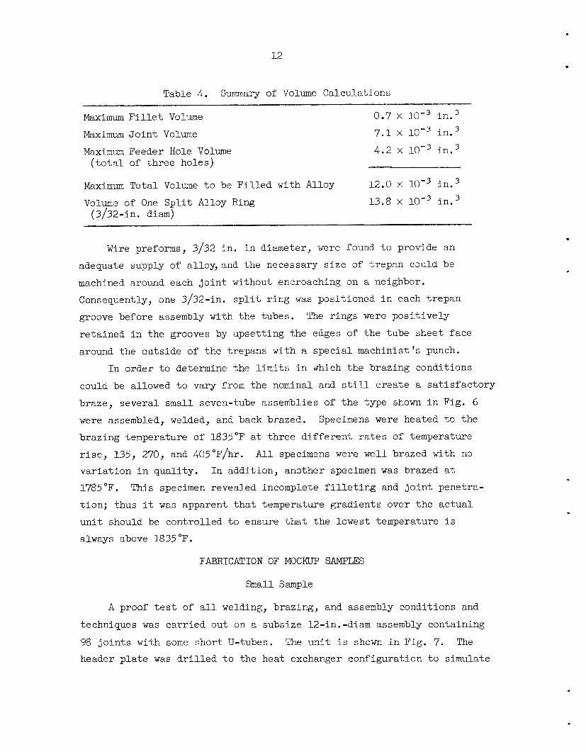
In order t o determine the l i m i t s i n which the brazing conditions
could be allowed t o vary from the nominal and s t i l l create a s a t i s f ac to ry braze, several small seven-tube assemblies of t he type shown i n Fig. 6
were assembled, welded, and back brazed. Specimens were heated t o the
brazing temperature of 1835°F a t three d i f f e ren t r a t e s of temperature
r i s e , 135, 270, and 405"F/hr. A l l specimens were wel l brazed with n3
var ia t ion i n qual i ty . In addition, another specimen w a s brazed a t
1785°F.
t ion ; thus it was apparent t h a t temperature gradients over t he ac tua l
u n i t should be controlled t o ensure that the lowest temperature i s
always above 1835 "F .
This specimen revealed incomplete f i l l e t i n g and j o i n t penetra-
FABRICATION OF M X K " SAMPUS
Small Sample
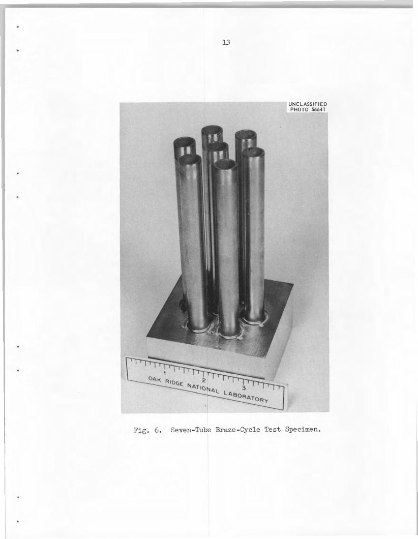
A proof t e s t of a l l welding, brazing, and assembly conditions and
techniques was carr ied out on a subsize 12-in.-diam assembly containing
98 j o i n t s with some short U-tubes. header p l a t e was d r i l l e d t o the heat exchanger configuration t o simulate
The un i t i s shown i n Fig. 7. The
Fig. 6. Seven-Tube Braze-Cycle Test Specimen. I
8
14
UNCLASSI FlED PHOTO 58284
._.- 1 . ,
.
Fig. 7 . Proof-Test Assembly Containing Short U-Tubes.
15 .
ac tua l heat flow conditions during brazing. A s an economy measure,
the trepanning, d r i l l i n g of the feeder holes, and appl icat ion of
brazing a l loy was l imited t o only half the tubes. Duwny s t a in l e s s
s t e e l tubes were tack-welded i n the remaining holes.
Inspection of the completed assembly revealed no weld defects and
excel lent brazes i n a l l j o i n t s except one, t h i s one j o i n t being
completely unbrazed. Metallographic examination of t h i s j o i n t revealed
small metal chips i n the j o i n t and a complete lack of wetting by the
brazing al loy. The apparent cause of t h i s condition was inadequate
cleaning of the pa r t s before assembly. Therefore, the importance of
cleanliness t o the brazing operation w a s g rea t ly emphasized. Special
handling and assembly procedures were in s t i t u t ed , and a ful l - t ime
inspector was assigned t o the job.
Large Sample
It w a s , of course, e s s e n t i a l t h a t the fabr ica t ion of the ac tua l
heat exchanger core be an unqualified success on the f i rs t attempt.
Suff ic ient mater ia l i n the form of INOR-8 tube sheet forgings and tubes
w a s avai lable f o r only one heat exchanger core, an3 replacement would
have meant about a one-year delay and a large f inanc ia l expenditure.
In addition, the s i z e of the un i t made it nscessary t o ship the heat
exchanger t o an outside vendor where it was t o be brazed i n a newly
fabricated r e t o r t . With these f a c t s i n mind and because of addi t ional
uncertaint ies remaining (such as the e f f ec t of large mass var ia t ions during brazing, r e t o r t i n t eg r i ty , assembly of long U-tubes, e t c . ) , it
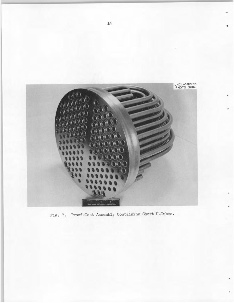
was decided t o bui ld a f u l l - s i z e sample heat exchanger core t o gain
fu r the r assurance of a l l stages of fabr icat ion. The sample, which i s
shown completed i n Fig. 8, contained nine fu l l - length U-tubes and
54 welded and back-brazed jo in t s . These j o i n t s were positioned i n the
center of the tube sheet and a t 3, 6, 9, and 12 o'clock posi t ions
around the periphery. A l l addi t ional tube holes were rough d r i l l e d and
a f u l l complement of dummy s t a in l e s s s t e e l tubes was f i t t e d i n order t o
simulate the expected gas and radiant heat baf f l ing e f f ec t s .
economy, the tube sheet w a s machined from ro l led p l a t e instead of from
a forging a s i n the ac tua l heat exchanger.
For
Aside from these few points,
16
UNCLASSlFl ED PHOTO 38928
,
.
Fig. 8. Completed Sample Heat Exchanger Positioned i n Welding- Inspection Fixture .
17
the sample was machined, assembled, welded, shipped, brazed,
inspected i n exact ly the manner planned f o r the ac tua l u n i t .
and
Inspection of the completed sample revealed a l l welds t o be f r ee
Ultrasonic and metallo- from porosity and a l l brazes f u l l y f i l l e t e d . graphic examination of t he brazed j o i n t s revealed only minor sca t te red
porosity.
The excel lent weld emtour , good weld penetration, and flow of the
brazing a l loy t o the root of the weld are evident.
A photomicrograph of one of these j o i n t s i s shown i n Fig. 9.
FABRICATION OF MSRE HEAT EXCHANGER TUBE BUNDLE
Welding and Brazing
Because of the success with the f u l l - s i z e sample, assembly of the
ac tua l heat exchanger tube bundle w a s not delayed. The tube sheet had
previously been machined and a l l tubes bent, degreased, and sealed i n
polyethylene bags.
After a f i n a l degreasing and inspection of the tube sheet, a l l
brazing a l loy r ings were inser ted and locked i n place by upset t ing the
face of the tlJbe sheet around the edge of the trepans. The tube sheet
was then mounted i n the assembly-welding f i x t u r e and the supporting
s t ruc ture of rod and ba f f l e s i n s t a l l ed , as shown i n Fig. 10. Several
tubes with compound bends were a l so i n s t a l l e d a t t h i s point since the
f i n a l bends had t o be made a f t e r being threaded through a l l the baf f les .
The U-tubes were assembled and welded one row a t a t i m e s t a r t i n g
adjacent t o the diametral flow separator and working outward. The welding conditions used were those presented previously. The setup f o r
welding i s shown i n Fig. 11. The torch assembly, spec ia l ly made for t h i s appl icat ion by the Union Carbide Nuclear Division, Y-12 General
Machine Shops, was provided with both coarse and micrometer adjustments
f o r centering over a j o in t . The torch w a s a l so adjustable i n the
v e r t i c a l direct ion. Circular movement w a s provided by a magnetic
p l a t e cam and knurled-pin follower located above the torch next t o the micrometer adjustment.
1% .
Fig. 9. Tube-To-Header J o i n t from Sample Heat Exchanger. Note excel lent weld contour, good weld penetration, and excel lent f low of brazing a l loy t o root of weld. 27X.
19 1 8
I
.
. Fig. 10. Tube Sheet with Baffles, Support Rods and Compound Bent
Tubes Ins ta l led .
20
Fig. 11. Specially Built Torch Positioned f o r Welding.
21
Special precautions were taken t o minimize contamination which
might la ter adversely a f fec t the brazing operation. four weeks t h a t were required f o r assembly, welding, and radiographic
inspection, the tube bundle was encased i n a polyethylene bag and the
tube sheet surface covered with a polyethylene sheet when continuous
access w a s not required. Along with these precautions, the welder and
mechanics wore clean, white cotton gloves, and personnel access t o the
room was l imited.
A l l through the
After welding and radiographic inspection, the tube bundle was
assembled i n the shipging container (Fig. 12) and sent t o Wall Colmonoy
Corporation, Detroi t , Michigan, f o r r e t o r t brazing i n dry hydrogen,
Furnace r ims were made on the empty r e t o r t t o clean the inner surface
and obtain an oxide-free environment f o r the ac tua l brazing operation.
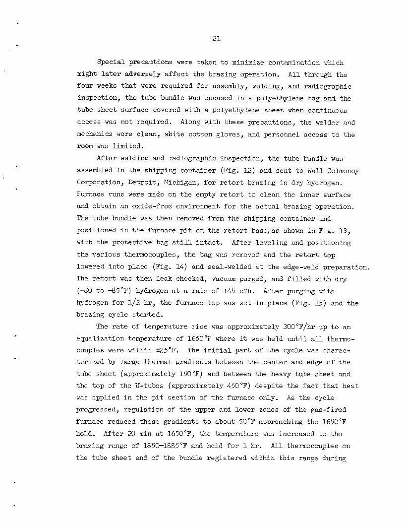
The tube bundle w a s then removed from the shipping container and
positioned i n the furnace p i t on the r e t o r t base,as shown i n Fig, 13, with the protect ive bag s t i l l i n t a c t . After level ing and posit ioning
the various thermocouples, the bag was removed and the r e t o r t top
lowered i n t o place (Fig. 14) and seal-welded a t the edge-weld preparation.
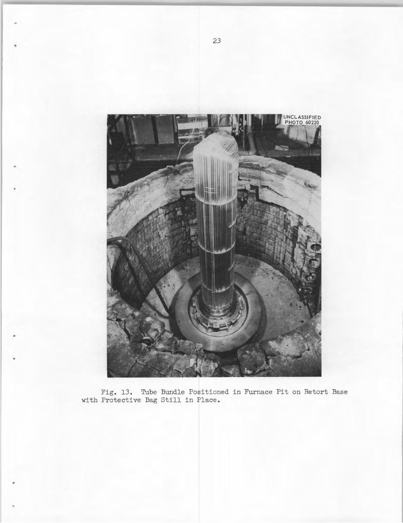
The r e t o r t was then leak checked, vacuum purged, and f i l l e d with dry
(-80 t o 4 5 ° F ) hydrogen a t a r a t e of 145 cfh. hydrogen f o r 1/2 hr , the furnace top was set i n place (Fig. 15) and the
brazing cycle s t a r t ed .
After purging with
The r a t e of temperature r i s e w a s approximately 300"F/hr up t o an
equalization temperature of 1650°F where it w a s held un t i l a l l thermo-
couples were within i25"F. The i n i t i a l pa r t of the cycle was charac- t e r i zed by la rge thermal gradients between the center and edge of t he
tube sheet (approximately 150°F) and between the heavy tube sheet and
the top 3f the U-tubes (approximately 450°F) despit, the f a c t t h a t heat
was applied i n the p i t sect ion of t he furnace only. A s t he cycle
progressed, regulation of the upper and lower zones of the gas-fired
furnace reduced these gradients t o about 50°F approaching the 1650°F
hold. brazing range of 1850-1885°F and held f o r 1 hr.
the tube sheet end of the bundle reg is te red within t h i s range during
After 20 min a t 1650°F, the temperature was increased t o the
All thermocouples on
22
3 ....-. .-*,-.- I - 1
i I
I
.
Fig. 12. Shipping Container for Tube Bundles.
.
. 23
.._ . .
Fig. 13. Tube Bundle Posit ioned i n Furnace P i t on Retort Base with Protect ive Bag S t i l l i n Place.
24
.
c
Fig. 14. Retor t Top i n Place for Seal Welding.
c
25
Fig. 15. Gas-Fired Furnace Top i n Place f o r Brazing Cycle.
26
the brazing cycle. A slow furnace cool a t about 3 O O 0 F / h r was main- ta ined t o below 300°F where an exothermic gas purge was introduced.
The r e t o r t was removed from the p i t , the s e a l weld cut , and the bundle
v isua l ly inspected.
Inspection
A photograph of several braze f i l l e t s i s presented i n Fig. 16, these being typ ica l of a l l v i s ib l e j o in t s . No d is tor t ion , discoloration,
lack of f i l l e t i n g , or other adverse conditions were noted. The bundle
was again bagged, assembled i n the shipping container, and returned t o
O a k Ridge f o r fu r the r inspection, t e s t s , and assembly in to i t s she l l .
F ina l inspection included a general dimensional check on the over-
a l l bundle (no detectable change) and dye-penetrant inspection of a l l
tube-to-tube sheet welds. No flaws were revealed. The brazed j o i n t s
were then inspected by a newly developed u l t rasonic technique.g
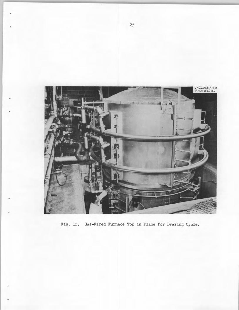
With the tubes f i l l e d with water, the u l t rasonic probe, which
contains a sending and receiving c rys t a l mounted a t a preset angle t o
each other, was ro ta ted 360 deg aro-and the inside of the tube and
indexed down the tube i n s teps t o f u l l y cover the brazed area. The
device, s e t up f o r inspecting the sample heat exchanger, i s shown i n Fig. 17. This inspection revealed somewhat more porosi ty i n the brazed
Jo in ts of the ac tua l heat exchanger than was observed i n the large
sample. Nevertheless, judging from signals from standardized defects,
it was believed t h a t t h i s porosi ty was sca t te red and of small s ize and t h a t the back brazes should cer ta in ly be an e f fec t ive secondary
s e a l i n case of inadvertent weld f a i l u r e i n service. Figure 18 shows
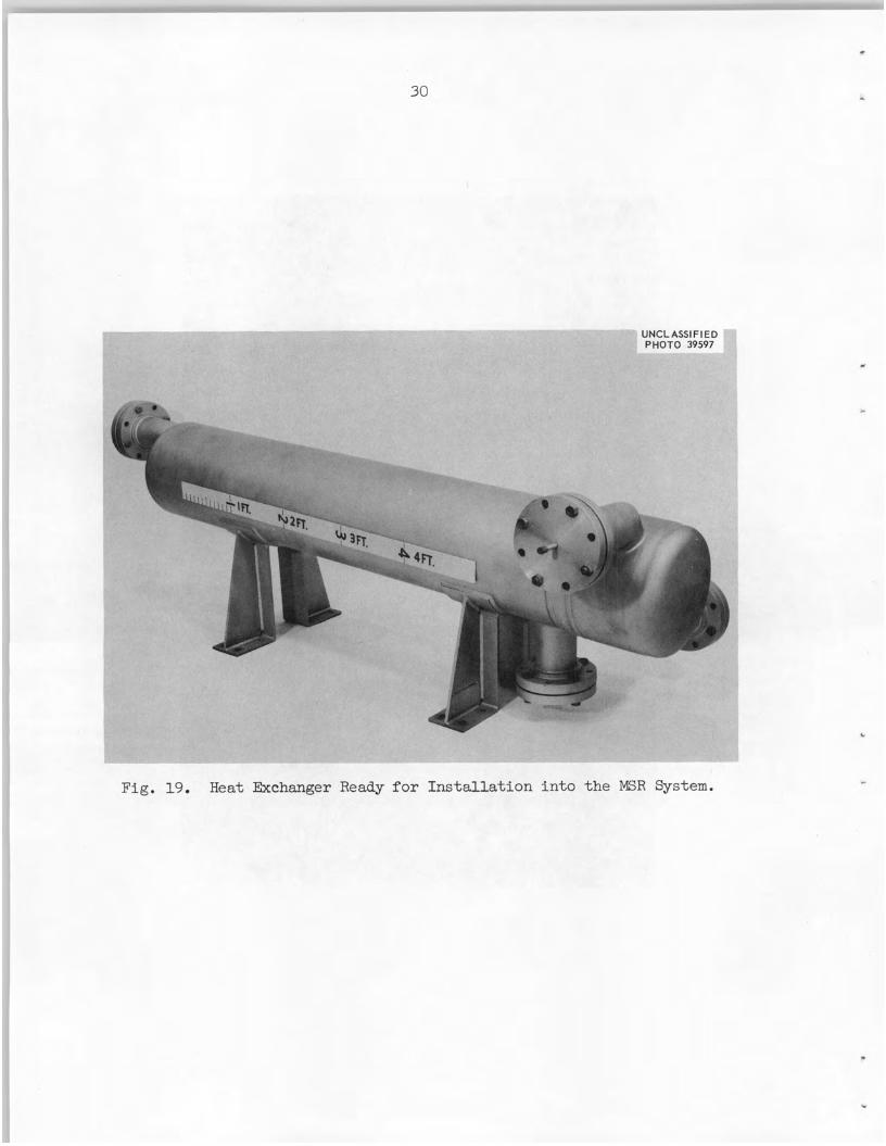
the completed tube bundle mounted on the f ix tu re . After welding the tube bundle i n t o i t s she l l , helium leak and
800-psi hydrostat ic tests were conducted. No leaks were found. The
completed heat exchanger i s shown i n Fig. 19 ready for i n s t a l l a t i o n i n
the MSR system.
'K. V. Cook and R. W. McClung, Welding J. 41(9) , 404s -08~ - - (Sept . 1962) .
. 27
.
UNCLASSIFIED
Fig. 16. Braze F i l l e t Area of H e a t Exchanger Typical of A l l Visible Jo in t s .
28
_-
Fig. 17. Ultrasonic Probe Device Set up on Sample Heat Exchanger To Inspect Tube-To-Tube Sheet-Brazed Jo in t s .
.
29
Fig. 18. Completed Tube Bundle Mounted in Fixture.
30
UNCLASSIFIED
- e
c
Fig. 19. Heat Exchanger Ready for Installation i n t o the MSR System.
.
'31
SUMMARY
A novel welded and back-brazed j o i n t design was used on the tube-
to-tube sheet i n t h i s heat exchanger because of the necessity f o r long-
term r e l i a b i l i t y . The double seal ing would give more confidence i n these
tube-to-tube sheet j o i n t s , which on many heat exchangers a re the areas
most prone t o f a i l u r e .
The development of both welding and brazing procedures was
necessary i n order t o determine the optimum fabr ica t ing techniques.
t h i s l i n e , sample components were welded and brazed under various con-
d i t ions , then inspected and tes ted . The s t rength of the brazed j o i n t s
and the e f f ec t of long-time aging on brazed j o i n t s were a l so investigated.
The r e s u l t s of these invest igat ions culminated i n the fabr ica t ion
In
of a heat exchanger tube bundle which required no repa i rs on e i t h e r
welds or brazes on any of the 326 tube-to-tube sheet j o i n t s and gives
every indicat ion of being able t o f u l f i l l i t s purpose i n the reactor
sys tem .
The authors g ra t e fu l ly acknowledge the work of L. G. Bryson i n
the preparation of t es t assemblies and assis tance i n fabr ica t ing the
heat exchanger, the planning and coordinating e f f o r t s of A. Taboada,
W. B. McDonald, and C. K. McGlothlan, and the engineering advice of
C. H. Wodtke. Many thanks a re due the Y-12 Shop personnel f o r t h e i r
heartening cooperation and personal i n t e r e s t throughout both the developmental and construction stages of t h i s pro jec t . Thanks are a l so
extended t o the Nondestructive Testing Development and Metallography
Groups of the Metals and Ceramics Division f o r t h e i r invaluable
ass is tance. The advice of the Wall Colmonoy technical staff and the patience of the shop personnel were both g rea t ly appreciated.
I
i
33 1
ORNL-3500 UC-25 - Metals, Ceramics, and Materials
TID-4500 (23rd ed. )
INTERNAL DISTRIBUTION
1-3. Central Research Library 4. Reactor Division Library
7-26. Laboratory Records Department 27. Laboratory Records, ORNL R.C. 28. K. V. Cook 29. J. E. Cunningham
30-49. R. G. Donnelly 50. C. W. Fox 51. J. H Frye, Jr. 52. W . R. G a l l 53. R. G. Gi l l i l and 54. H. L. Hemphill
60. C . E. Larson 61. H. G. MacPherson
55-59. M. R. H i l l
62. W. D. Manly 63. W . R. Martin 64. R. W. McClung 65. S. A. Rabin 66. J. L. Redford 67. M. J. Skinner 68. G. M. Slaughter 69. J. A. Swartout 70. J. R. Tallackson 71. W. C. Thurber 72. A. M. Weinberg 73. R. E. Worsham 74. A. A. Burr (consul tant) 75. J. R. Johnson (consul tant) 76. C. S. Smith (consul tant) 77. R. Smoluchowski (consul tant)
EXTERNAL DISTRIBUTION
78. C. M. Adams, Jr., MIT
81. D. E. Baker, GE, Hanford 82. E r se l Evans, GE, Hanford 83. J. L. Gregg, Cornell University 84. J. Simmons, AEC, Washington 85. E. E. Stansbury, University of Tennessee 86. Donald K. Stevens, AEC, Washington 87. Research and Development Division, AFX, OR0
79-80. David F. Cope, OR0
88-594. Given d i s t r ibu t ion as shown i n TID-4500 (23rd ea . ) under Metals, Ceramics, and Materials category