For contacting, [email protected]Mechanical Engineer Table of Contents IC Engine Practical.................................................. 2 Introduction and objective..........................................2 Equipment and tools used............................................2 Procedure...........................................................3 The Main part of the Engine and main Function.......................7 The operation principle of 4 stroke engine..........................9 Intake stroke.....................................................9 Compression stroke................................................9 Ignition stroke...................................................9 PV diagram.........................................................10 Differences between our engine and others engines..................11 Extra information..................................................11 Arrangement for IC four stroke...................................11
IC Engine Practical.......................................................................................................................................2
Introduction and objective......................................................................................................................2
Equipment and tools used.......................................................................................................................2
Introduction and objectiveWhat meant by IC engine is internal combustion Engine as one type of the engines. In
this particular engine, the burning of fuel inside the cylinder (chemical reaction resulting thermal energy) will increase in pressure which needs more volume to be occupied by the gas. That will derive the piston to move downward to bottom dead center of the cylinder. That will result mechanical motion (linearly) which will transfer to rotary motion in the crank shaft leading to drive the load through the fly wheel. In addition, the engine that will be covered it take four stroke to form a full cycle. The four strokes are: Intake, compression, power and exhaust strokes.
In this report the process of dismantling and reassembling the engine as well as the tools and equipment used in the process will be described.
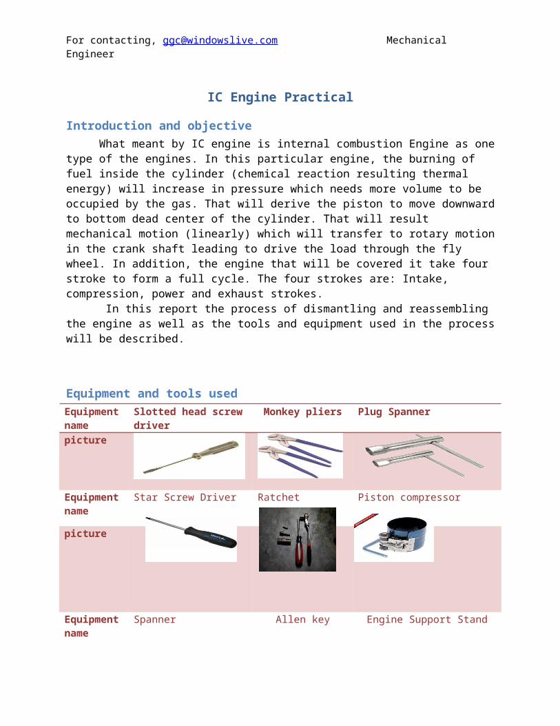
Equipment and tools usedEquipment name
Slotted head screw driver Monkey pliers Plug Spanner
item number description Function material1 Flywheel Storing Kinetic energy during the
period of power stroke and release it to have enough energy during the requirement of energy (compression stroke). And o keeps the continuity of rotation for the crank shaft.
Cast iron
2 Crank Shaft The crankshaft transforms the linear motion of the pistons into a rotational motion that is transmitted to the load.
Alloy Steel
3 Connecting rod
The connecting rod connects the piston to the crankshaft
Aluminum
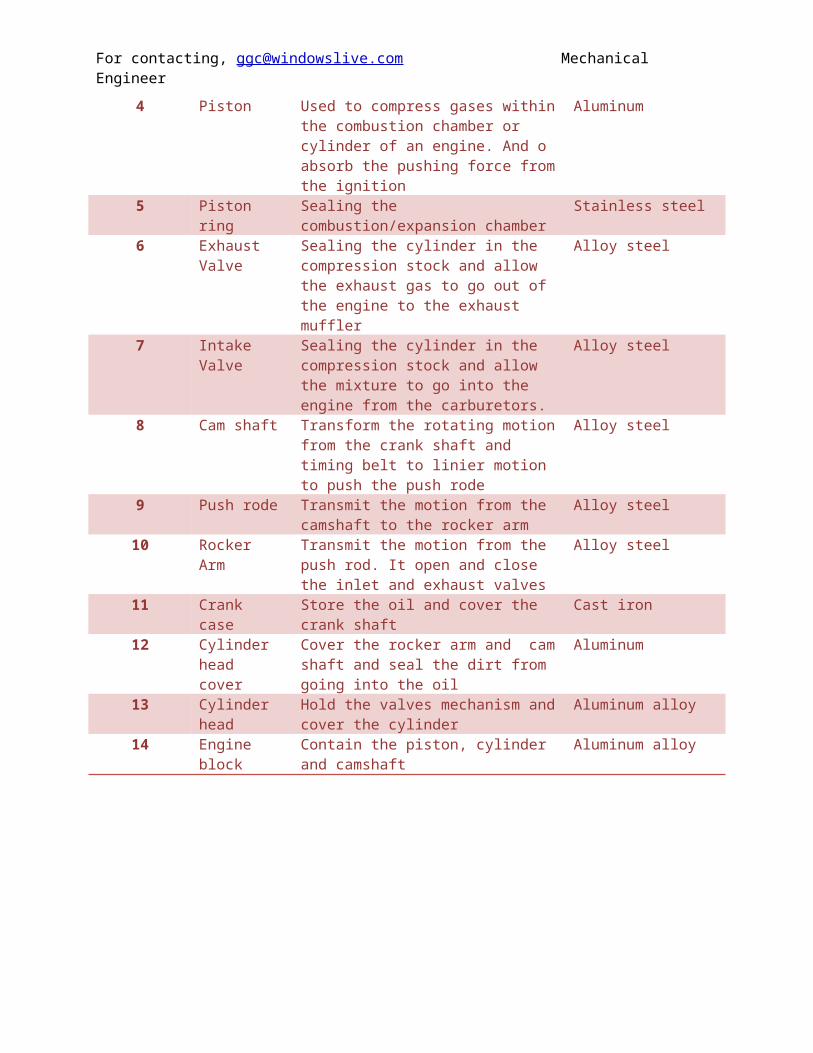
4 Piston Used to compress gases within the combustion chamber or cylinder of an engine. And o absorb the pushing force from the ignition
Aluminum
5 Piston ring Sealing the combustion/expansion chamber
Stainless steel
6 Exhaust Valve Sealing the cylinder in the compression stock and allow the exhaust gas to go out
The operation principle of 4 stroke engineThis type of engine has a cycle of 4 strokes happen when the crank shaft rotates 360 degree.
The cycle consists of intake, compression, ignition and exhaust stroke.
Intake stroke
(Taking in air-fuel mixture)
In this stroke, the intake valve opened and exhaust valve closed. The mixture of air and fuel will be sucked into the cylinder from the carburetor. This because expansion of the volume in the cylinder cased by the downward motion of the piston to bottom dead center. That can lead to create vacuum in the cylinder.
Compression stroke
(Squeezing the air-fuel mixture into a smaller volume)
In this stroke, both intake and exhaust valve are closed .the mixture of air and fuel is compressed to make it easier to ignite , this because the volume of the cylinder will be reduced due to the movement of the piston upward to top dead center.
Ignition stroke
(Burning the air-fuel mixture and forcing the piston down)
In this stroke, both intake and exhaust valve are closed. The spark plug will inject a ignition spark to ignite the compressed mixture. The piston then wills pushed down ward to bottom dead center by the high pressure gas.
In this stroke, the energies come from fly wheel and the motion of other piston will move the piston upward to top dead center .the intake valve will be remain close and the exhaust will be opened to allow the exhaust gas going to the exhaust muffler.
The following PV diagram will show graph illustrate the pressure verses the volume in the cylinder during the four different stroke.
As it can be seen from the graph, the relation between the pressure and volume is inversely proportional, as the volume degrease, the pressure will increase. The pressure will be highest during the power stroke at top dead center. Whereas, the cylinder will have low pressure when the volume increase in intake stroke at bottom dead center.
PV diagram
The idealized four-stroke Otto cycle p-V diagram: the intake (A) stroke is performed by an isobaric expansion, followed by the compression (B) stroke, performed by an adiabatic compression. Through the combustion of fuel an isochoric process is produced, followed by an adiabatic expansion, characterizing the power (C) stroke. The cycle is closed by an isochoric process and an isobaric
compression, characterizing the exhaust (D) stroke.
Differences between our engine and others engines
The idea and concepts are the same in the engines. However, there are little bet things are different which I will explain it now.
First thing I noticed that our engine is vertical engine while the engine with other group is V type.
The arrangement for cam shaft is different. In our engine we have only one cam shift whiles the other have two.
The valves are not the same with other group valves. In our engine we have springs to return valves to the same place to close. While others don’t have
For the timing mechanism, in our engine we have chain which is connected between cam shifts and the crank shift. Whereas, the other engine don’t have chain, it have rubber time belt.
Extra information
Arrangement for IC four stroke
Basic Engine PartsThe core of the engine is the cylinder, with the piston moving up and down inside the cylinder. The engine described above has one cylinder. That is typical of most lawn mowers, but most cars have more than one cylinder (four, six and eight cylinders are common). In a multi-cylinder engine, the cylinders usually are arranged in one of three ways: inline, V or flat (also known as horizontally opposed or boxer), as shown in the following figures.
Shape of the engine
Figure 2. Inline - The cylinders are arranged in a line in a single bank.
A single overhead camshaft cylinder head from a 1987 Honda CRX Si.
Single overhead camshaft (SOHC) is a design in which one camshaft is placed within the cylinder head. In an inline engine this means there is one camshaft in the head, while in a V engine or a horizontally-opposed engine (boxer; flat engine) there are two camshafts: one per cylinder bank.
Double overhead camshaft
Overhead view of Suzuki GS550 head showing dual camshafts and drive sprockets.
A double overhead camshaft valve train layout is characterized by two camshafts located within the cylinder head, one operating the intake valves and one operating the exhaust valves. Some engines have more than one bank of cylinder heads (V8 and flat-four being two well-known examples) and these have more than two camshafts in total, but they remain DOHC. The term "twin cam" is imprecise, but will normally refer to a DOHC engine. Some manufacturers still managed to use a SOHC in 4-valve layouts