ICC-ES Evaluation Reports are not to be construed as representing aesthetics or any other attributes not specifically addressed, nor are they to be construed as an endorsement of the subject of the report or a recommendation for its use. There is no warranty by ICC Evaluation Service, LLC, express or implied, as to any finding or other matter in this report, or as to any product covered by the report.
ICC-ES Evaluation Report ESR-2994 Reissued August 2021
This report is subject to renewal August 2023.
www.icc-es.org | (800) 423-6587 | (562) 699-0543 A Subsidiary of the International Code Council ®
DIVISION: 06 00 00—WOOD, PLASTICS AND COMPOSITES
Section: 06 17 33—Wood I-joists
REPORT HOLDER:
REDBUILT LLC
EVALUATION SUBJECT:
RED-I™ PREFABRICATED WOOD I-JOISTS
1.0 EVALUATION SCOPE
Compliance with the following codes:
2018, 2015, 2012 and 2009 International Building Code®
(IBC)
2018, 2015, 2012 and 2009 International ResidentialCode® (IRC)
For evaluation for compliance with codes adopted by the Los Angeles Department of Building and Safety (LADBS), see ESR-2994 LABC and LARC Supplement.
Properties evaluated:
Structural
Sound ratings
Fire-resistance ratings
2.0 USES
Red-I joists are prefabricated wood I-joists used as floor joists, roof rafters and blocking panels, to support code-required loads. Red-I joists described in Table 1 are also used as rim joists, to provide the transfer of vertical loads at the rim joist location, diaphragm attachment, and transfer of lateral loads. Prefabricated wood I-joists described in this report comply with Section 2303.1.2 and 2303.1.13 of the IBC, for allowable stress design, and Section R502.1.2 and R502.1.7 of the IRC (Section R502.1.4 of the 2012 and 2009 IRC).
3.0 DESCRIPTION
3.1 General:
Red-I joists are prefabricated wood I-joists having wood or wood-based flanges and oriented strand board (OSB) webs. Either the top and bottom flanges are parallel, forming a constant-depth joist (non-tapered); or the web at the top flange location has a single taper, forming a variable-depth joist (tapered). Red-I45, -I65, and -I90 are available as tapered and non-tapered I-joists. The remaining I-joists are non-tapered. The web panels have the face grain oriented vertically, and the web-to-web connection is either butt
jointed or serrated and glued to form a continuous web. The web-to-flange connection is a proprietary tongue-and-groove glued joint. Refer to Table 1 for Red-I joist series and material descriptions.
3.2 Material Specifications:
3.2.1 Flanges: Flange material is RedLam™ laminated veneer lumber (LVL) that meets the requirements noted in the approved quality documentation that contains RedBuilt™ manufacturing standards. The assigned allowable tension stresses for RedLam™ LVL flanges are verified in accordance with the procedures set forth in the approved quality documentation. Table 1 of this report specifies flange material, widths and depths. Flange material and grades are as specified in the quality documentation that contains RedBuilt™ manufacturing standards.
3.2.2 Webs: Web material is OSB conforming to DOC Voluntary Product Standard PS2, Exposure 1, along with further requirements set forth in the quality documentation that contains RedBuilt™ manufacturing standards. Web material thickness requirements are noted in Table 1 of this report.
3.2.3 Adhesives: Adhesives are of the types specified in the quality documentation that contains RedBuilt™ manufacturing standards.
4.0 DESIGN AND INSTALLATION
4.1 General:
The design and installation of Red-I joists described in this report must comply with Sections 4.2 through 4.16. Additionally, design of Red-I joists is governed by the applicable code and corresponding editions of ANSI/AWC National Design Specification® for Wood Construction (NDS).
4.2 Design Values:
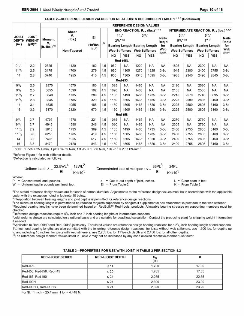
Table 2 specifies reference design moments, reactions, vertical shear forces, and joist stiffness (EI). Reference design reactions are based on minimum bearing lengths of 13/4 inches, 21/2 inches and 31/2 inches (45, 64 and 89 mm), for simple spans; and 31/2, 51/4 and 7 inches (89, 133 and 178 mm) at intermediate support points for continuous spans. Tapered joists and custom depth parallel flange joists are designed in accordance with the approved quality documentation and are provided by RedBuilt. When joists in Table 2 are used as multiple span members, and subject to uniform load only, the calculated shear force used for design at the intermediate support may be reduced by the percentage determined from the following formula and limited to the depths shown in Table 3:
ESR-2994 | Most Widely Accepted and Trusted Page 2 of 16
R = W ÷ K ≤ 18%
where:
K = V12 ÷ 100.
R = The percent reduction.
V12 = The reference design shear for an 117/8-inch-deep (302 mm) non-tapered joist (pounds).
W = The uniform load (plf).
For the Red-I joists in Table 2, the reference design shear at the interior supports of multiple-span-member Red-I joists up to 12 inches (305 mm) deep, used in residential floor construction, is permitted to be increased by 10 percent. This increase in allowable design shear does not apply to the design shear at the ends of the joists.
4.3 Fasteners:
For Red-I joists, reference lateral and withdrawal design loads for fasteners installed into the flanges are as prescribed in the applicable code for sawn lumber having a minimum specific gravity of 0.50, such as for Douglas fir-larch.
Allowable nail spacings for Red-I joist diaphragm applications must be as specified in Sections 4.14 and 4.15 of this report.
For nondiaphragm applications:
1. The spacing of fasteners installed into the face grain of RedLam LVL flanges must be greater than or equal to the closest permitted on-center spacing prescribed by the code for fasteners installed in sawn lumber.
2. The spacing of fasteners installed into the edge grain of RedLam LVL flanges must be greater than or equal to 4 inches (152 mm) on center for nail diameters less than or equal to 0.148 inches (3.76mm) or 8 inches (203 mm) on center for 16d by 31/2-inch (89 mm) common nails.
For the Red-I joists in Table 2, the allowable lateral load capacity of 10d by 11/2-inch-long (38 mm) common nails used to connect minimum No. 18 gage [0.048 inch (1.2 mm) base-metal thickness] metal straps or tension-ties, recognized in a current ICC-ES evaluation report, to Red-I joist flanges, in conformance with Figure 5 of this report, is 112 pounds-force (498 N) per nail. The connections with the structural composite lumber flanges may be used for out-of-plane wall anchorage to flexible diaphragms in lieu of the minimum 21/2-inch (63.5 mm) wood element thickness as required by code.
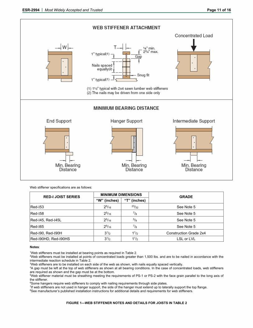
4.4 Web Stiffeners:
Web stiffener requirements for reactions and concentrated loads are noted in Table 2 and Figure 1.
4.5 Lateral Support:
The top flange requires continuous lateral support throughout the entire length by direct-applied sheathing. Joists with flange widths less than 2.3 inches (58 mm) require lateral support of the flange every 18 inches (457 mm) on center. Red-I joists with flange widths equal to or greater than 2.3 inches (58 mm) require lateral support of the flange every 24 inches (610 mm) on center. Each connection assumed to provide lateral support, such as connections to sheathing, must be capable of transmitting a 75-pound-force (334 N) horizontal load.
For cases in which the bottom flange is in compression, it must either be continuously laterally supported as described above, or the necessary lateral restraint of the bottom flange
and corresponding beam stability factor, CL, must be determined through analysis in accordance with 2012 NDS Section 7.3.5.3.
All Red-I joist ends require restraint to prevent rollover. Code-prescribed methods of lateral restraint specified for sawn lumber are acceptable. Bridging is not required for floor and roof Red-I joist applications.
4.6 Holes in Red-I Joist Web:
Holes, designed in accordance with the equations of this section, are permitted in the webs of Red-I joists for all joists listed in Table 1, including for use in the fire-resistance-rated assemblies B, C, D, E and F described in Section 4.17 and Assembly G described in Section 4.18, with the exception of the Red-I 90HD Series, which has not been evaluated for holes.
Round Hole:
Design allowable shear at centerline of hole:
Square or Rectangular Hole Where Both H and L are Less than or Equal to D'-2d:
Design allowable shear at centerline of hole:
100
%008.0)70%(72.067.0
)(
WHWHorMAX
LorHMAX
Rectangular (Duct) Hole Where H=D’-2d, D' 20" and L 1.5D':
Design allowable shear at edge of hole of non-tapered I-joists, unless specified:
Red-I45L and I53:
Vhole = 364 – 11.6 L
(Maximum L = 14")
Red-I58 and I45:
Vhole = 409 – 11.6 L
= 368 – 10.4 L (for tapered Red-I45)
(Maximum L = 18")
Red-I65 and I90:
Vhole = 479 – 11.6 L
= 388 – 9.4 L (for tapered Red-I65 and -I90)
(Maximum L = 24")
Red-I90H and I90HS:
Vhole = 696 – 11.6 L
(Maximum L = 24")
where:
'
''hole
D
DDV rV
D
DV rV
'
''hole
ESR-2994 | Most Widely Accepted and Trusted Page 3 of 16
d = Flange depth (in)
D = Hole diameter (in)
D' = Out to out joist depth (in)
H = Maximum hole height (in)
L = Maximum hole length (in)
Vhole = Allowable hole shear (lb)
Vr' = Adjusted design shear value, based on Vr
from Table 2, adjusted in accordance with NDS Section 7.3 (lb)
WH% = Percentage of hole height relative to web depth = [Max(H or L) / (D'-2d)] *100
Holes are not allowed in cantilever areas unless specifically designed by a qualified design professional.
Where more than one hole is to be cut in the web, the clear distance between holes must be twice the length of the longest dimension of the largest adjacent hole.
Analysis of the allowable hole size on tapered joists must consider distance from support and depth of joist at the desired hole location.
4.7 Duration of Load:
Increases for duration of load, as provided for wood members and their connections, shall be in accordance with the limitations specified in the applicable code and as set forth in this report, unless specifically prohibited by this report.
4.8 In-service Moisture Conditions:
Reference design values given in this evaluation report reflect dry service conditions, where the moisture content in service is less than 16 percent. Wet service use is outside the scope of this evaluation report.
4.9 Repetitive-member Use:
The repetitive-member use factor applicable to the resistive moment capacities listed in Table 2 is limited to 1.0.
4.10 Member Spans:
Red-I joist spans must be determined in accordance with Part 3.2.1 of the NDS. Vertical shear calculations must include all loads within the span from face to face of supports.
4.11 Deflection:
Deflection of simple span Red-I joists with either uniform load or a concentrated load at midspan is determined using the formulas in the footnotes to Table 2.
4.12 Blocking Panels:
Bearing walls perpendicular to and supported by Red-I joists at the end or intermediate supports, or both, require full-depth blocking. When used as blocking panels, Red-I joists noted in Table 2 have an allowable vertical uniform load transfer capacity of 2,100 plf (30,645 N/m) for joist depths up to and including 16 inches (406 mm), and 1,550 plf (22,620 N/m) for joist depths over 16 inches (406 mm) and up to 20 inches (508 mm).
4.13 Rim Joists:
Red-I joists with 11/2-inch-thick flanges in Table 2 having depths of up to and including 16 inches (406 mm) may be used as rim joists and boundary members of horizontal wood structural diaphragms. The joists have an allowable uniform vertical load transfer capacity of 2,100 plf (30,645 N/m) and lateral in-plane shear capacity of 260 plf
(3,795 N/m). Red-I joists used as rim joists must be laterally supported at the top and continuously supported at the bottom, and the gravity loads must be uniformly applied along the top. Other loading and support conditions must be investigated by a design professional, and approved by the code official.
4.14 Red-I Joists as Prescriptive Diaphragm Framing Members:
Red-I joists are permitted as framing members in prescriptive floor and roof diaphragm construction in accordance with Section 2308 of the IBC and Chapters 5 and 8 of the IRC.
4.15 Red-I Joists as Engineered Diaphragm Framing Members:
Red-I joists may be used as framing members in diaphragms designed in accordance with the applicable code. The closest permitted sheathing nail spacing for 11/2-inch flange depth in a single row is 3 inches (76 mm) on center for 10d common nails or 2 inches (51 mm) on center for 8d common nails. The closest permitted sheathing nail spacing for 13/8-inch flange depth in a single row is 4 inches (76 mm) on center for 8d and 10d common nails.
4.16 Cantilevered Red-I Joists:
Red-I joists are permitted to be installed with cantilevered ends, provided the cantilevers have a maximum length equal to one-third of the adjacent span and support uniform loads only, unless designed by a design professional.
4.17 One-hour Fire-resistance-rated Roof-ceiling or Floor-ceiling Assemblies Using Joists Described in Table 1:
Refer to Figure 2 for details. For assemblies A, B, C, D, E and F, used as floor-ceiling assemblies over unusable crawl spaces, it is permitted to omit the ceiling membrane. Additionally, flooring is permitted to be omitted where unusable attic space occurs above, provided the lateral support requirements of Section 4.5 are met. The assemblies must be constructed in accordance with one of the assembly descriptions given in Sections 4.17.1 through 4.17.6.
4.17.1 Assembly A:
1. A double wood floor consisting of a subfloor of nominally 1-inch-thick (25.4 mm), tongue-and-groove sheathing or 32/16 span-rated sheathing (Exposure 1); and a second layer of nominally 1-inch-thick (25.4 mm), tongue-and-groove finish flooring. Alternatively, the finish flooring is permitted to be 40/20 span-rated sheathing (Exposure 1), or Type I, Grade 1, particleboard not less than 5/8 inch (15.9 mm) thick.
All butt joints of the sheathing must be located over framing members.
When use is as a roof-ceiling assembly, a single layer of square-edge span-rated sheathing (Exposure 1), complying with the code, is permitted to be used for roof sheathing.
2. Red-I joists described in Table 1 with a minimum flange depth of 11/2 inches (38 mm) must be installed in accordance with this report at a maximum spacing of 48 inches (1219 mm) on center.
3. The suspended ceiling must consist of 5/8-inch-thick (15.9 mm), 2-foot-by-2-foot (610 mm by 610 mm) or 2-foot-by-4-foot (610 mm by 1219 mm), USG FIRECODE AURATONE lay-in acoustical board supported by an approved, exposed fire-resistance-
ESR-2994 | Most Widely Accepted and Trusted Page 4 of 16
rated suspension system attached to the joist bottom flange or to cold-rolled channels spaced not more than 48 inches (1219 mm) on center. When Red-I joists are spaced more than 24 inches (610 mm) on center, framing perpendicular to the joists must be installed at 24 inches (610 mm) on center to support the ceiling. The distance from the bottom of the Red-I joists to the soffit of the ceiling must be a minimum of 10 inches (254 mm).
4. Installed over the acoustical board are minimum 1-inch-thick (25.4 mm), 4 pcf (64 kg/m3), Thermafiber® Sound Attenuation Fire Blankets, Fibrex®-FBX 1240 Industrial Boards, Fibrex®-IF 1240 Flex Batts, IIG MinWool®-1240 Industrial Board or IIG MinWool®-1240 Flexible Batt.
5. Light fixtures having a maximum size of 2 feet by 4 feet (610 mm by 1219 mm) are permitted to be installed in the ceiling, provided the aggregate area of fixtures does not exceed 12 square feet per 100 square feet (1.1 m2 per 9.3 m2) of ceiling area and the fixtures are protected as follows [using, for illustration, a 2-foot-by-4-foot (610 mm by 1219 mm) fixture]: A 21/4-inch-by-48-inch (57 mm by 1219 mm), minimum 11/4-inch-thick (31.8 mm) piece of minimum 4 pcf (64 kg/m3) Thermafiber rigid mineral fiber board or Fibrex-FBX 1240 Industrial Board or Fibrex-IF 1240 Flex Batt light fixture protection, is laid along the long sides of the fixture, and against adjacent suspension members; two pieces of the same insulation, measuring 191/2 inches by 48 inches (495 mm by 1219 mm), are laid over the top of the fixture, and a 41/2-inch-by-24-inch (114 mm by 610 mm) piece of the same insulation is laid at each end and tied at the corners of the fixture, to the top pieces using No. 18 SWG steel wire. See Figure 4 for details. In addition, ceiling openings for air diffusers, up to a maximum of 12 inches (305 mm) in diameter, are permitted, provided openings are protected with approved fire dampers and the aggregate areas do not exceed 113 square inches (72 900 mm2) per 100 square feet (9.3 m2) of ceiling area.
4.17.2 Assembly B:
1. The flooring must consist of a single layer of 48/24 span-rated, tongue-and-groove, sheathing (Exposure 1). Construction adhesive conforming to ASTM D3498 must be applied to the top of the joists prior to placing sheathing. When used as a roof-ceiling assembly, the decking is permitted to be any wood deck recognized in the code. All butt joints of the sheathing must be located over framing members.
2. Red-I joists described in Table 1 must be installed in accordance with this report, with a maximum spacing of 24 inches (610 mm) on center for floor-ceiling assemblies. When used in roof-ceiling assemblies, the joists are permitted to be spaced a maximum of 48 inches (1219 mm) on center.
3. Optional minimum 31/2-inch-thick (89 mm) glass fiber insulation or glass fiber insulation rated R-30 or less may be installed in the joist plenum when resilient channels are used. The insulation must be placed above the resilient channels between the joist bottom flanges.
4. The ceiling membrane must consist of two layers of 1/2-inch-thick (12.7 mm) Gold Bond Fire-Shield C (FSW-C), or two layers of 5/8-inch-thick (15.9 mm), Type X gypsum board complying with ASTM C36, attached to the Red-I joist bottom flange.
5. The first layer of gypsum board must be installed perpendicular to the Red-I joists and attached using
15/8-inch-long (41 mm), Type S screws spaced 12 inches (305 mm) on center. The second layer must be installed with the joints staggered from the first layer. The second layer must be fastened to the Red-I joists with 2-inch-long (51 mm), Type S screws spaced 12 inches (305 mm) on center in the field and 8 inches (203 mm) on center at the butt joints.
Type G screws, 11/2 inches (38 mm) long, must be spaced 8 inches (203 mm) on center and 6 inches (152 mm) from each side of the transverse joints of the second layer. The second layer must be finished with joint tape and compound.
6. Resilient channels (RC-1) are permitted to be used as part of the ceiling attachment system, provided they are spaced 16 inches (406 mm) on center [24 inches (610 mm) on center if the joists are spaced 16 inches (406 mm) on center] and fastened perpendicular to the Red-I joists using 1-inch-long (25.4 mm), Type S screws. When resilient channels are used, the first layer of the ceiling membrane must be installed perpendicular to the channels and attached to the resilient channels using 1-inch-long (25.4 mm), Type S screws spaced 12 inches (305 mm) on center. The second layer must be installed with the joints staggered from the first layer and attached using 15/8-inch-long (41 mm), Type S screws. The screw spacing for the second layer of gypsum board must be a maximum of 12 inches (305 mm) on center in the field and 8 inches (203 mm) on center at the butt joints.
Type G screws, 11/2 inches (38 mm) long, must be spaced 8 inches (203 mm) on center and 6 inches (152 mm) from each side of the transverse joints of the second layer. The second layer must be finished with joint tape and compound.
7. In roof-ceiling assemblies in which the Red-I joists are spaced more than 24 inches (610 mm) on center, the ceiling, including the resilient channels, must be applied to stripping spaced 24 inches (610 mm) on center. The attachment of the ceiling membrane to the stripping members must be similar to the attachment of the ceiling membrane to the Red-I joists. The stripping must be a minimum of nominally 2-by-4 construction-grade Douglas fir lumber for spans up to 5 feet (1524 mm), and must be attached to the joist bottom flange using a minimum of two 10d box nails. Stripping materials of equivalent strength and attachment are permitted when approved by the code official.
4.17.3 Assembly C:
1. The flooring must consist of a single layer of 48/24 span-rated, tongue-and-groove sheathing (Exposure 1). Construction adhesive conforming to ASTM D3498 must be applied to the top of the joists prior to placing sheathing. When use is as a roof-ceiling assembly, a single layer of square-edge span-rated sheathing (Exposure 1), complying with the code, is permitted to be used for roof sheathing. All butt joints of the sheathing must be located over framing members.
2. Red-I joists described in Table 1 must be installed in accordance with this report, with a maximum spacing of 24 inches (610 mm) on center for floor-ceiling assemblies. When use is in roof-ceiling assemblies, the joists are permitted to be spaced a maximum of 48 inches (1219 mm) on center. When the joist spacing exceeds 24 inches (610 mm) on center, framing perpendicular to the joists must be installed at 24 inches (610 mm) on center to support the ceiling.
ESR-2994 | Most Widely Accepted and Trusted Page 5 of 16
3. The ceiling membrane must be installed perpendicular
to the Red-I joists or stripping, and must consist of a single layer of 1/2-inch-thick (12.7 mm) Gold Bond Fire-Shield C (FSW-C), or 5/8-inch-thick (15.9 mm), Type X gypsum board complying with ASTM C36, and attached to the joists, or to stripping spaced 24 inches (610 mm) on center. The gypsum board must be fastened using 15/8-inch-long (41 mm), Type S screws located 6 inches (152 mm) on center at end joints and 8 inches (203 mm) on center in the field.
4. An approved, exposed, fire-resistance-rated, suspended-ceiling system must be installed beneath the gypsum board ceiling membrane. The minimum distance between the suspended ceiling and the gypsum board ceiling membrane must be 12 inches (305 mm). The grid system must be suspended with No. 12 SWG galvanized steel wire fastened to the stripping or joists using 3-inch-long (76 mm) flathead hanger screws. Light fixture protection must consist of 6-inch-wide (152 mm) pieces of ceiling grid panels that are 48 inches (1219 mm) long for the sides, and 24 inches (610 mm) long for the ends, with a full grid panel placed on top.
A galvanized steel duct is permitted for each 200 square feet (18.6 m2) of ceiling, provided the duct has a maximum 12-inch-diameter (305 mm) steel diffuser opening without a damper, and a maximum 6-inch-by-12-inch (152 mm by 305 mm) return air opening. Ceiling panels must be 5/8-inch-thick (15.9 mm), USG FIRECODE AURATONE. Glass fiber batt insulation rated R-30 or less is permitted to be installed above the gypsum board, in the cavity between the joists.
4.17.4 Assembly D:
1. The flooring must consist of a single layer of 48/24 span rated, tongue-and-groove sheathing (Exposure 1). When use is as a roof-ceiling assembly, a single layer of square-edge, span-rated sheathing (Exposure 1), complying with the code, is permitted to be used for roof sheathing. All butt joints of the sheathing must be located over framing members.
2. The Red-I joists described in Table 1 must have a minimum flange depth of 13/8 inches (35 mm), and be installed in accordance with this report, with a maximum spacing of 24 inches (610 mm) on center.
3. The ceiling membrane must consist of a single layer of 1/2-inch-thick (12.7 mm) USG FIRECODE® Type C gypsum board or ProRoc® Type C gypsum board screw-attached to steel furring channels placed perpendicular to the joists. The furring channels must be spaced 24 inches (610 mm) on center and are attached and suspended from the joists using No. 24 gage proprietary attachment clips designated “Simpson Strong-Tie CSC Support Clips”. A CSC support clip must be located at each joist, to support the furring channel. At channel splices, adjacent pieces are overlapped a minimum of 6 inches (152 mm), and are tied with double-strand No. 18 SWG galvanized steel wire at each end of the overlap.
4. A layer of 1-inch-thick (25.4 mm), minimum 6 pcf (96 kg/m3), Thermafiber Type CW 90 mineral-wool blanket, Fibrex-FBX 1280 Industrial Board, Fibrex-IF 1280 Flex Batt, IIG MinWool 1260 Industrial Board or IIG MinWool 1260 Flexible Batt must be placed below the bottom flanges of the joists and on top of the furring channels. Alternatively, a layer of 2-inch-thick (51 mm) Thermafiber mineral-wool blanket, having a density of 8 pcf (128 kg/m3), is permitted to be used.
4.17.5 Assembly E:
1. The flooring must consist of a double wood floor as described in Section 4.17.1, Assembly A, or a single layer of 48/24 span-rated, tongue-and-groove sheathing (Exposure 1). When a single-layer floor is used, a construction adhesive conforming to ASTM D3498 must be applied to the top of the joists prior to placing sheathing. When joists are used in a roof-ceiling assembly, a single layer of square-edge, span-rated sheathing (Exposure 1), complying with the code, is permitted to be used for roof sheathing. All butt joints of the sheathing must be located over framing members.
2. Red-I joists described in Table 1 must be installed in accordance with this report, with a maximum spacing of 24 inches (610 mm) on center for floor-ceiling assemblies, and a maximum spacing of 48 inches (1219 mm) on center for roof-ceiling assemblies. When the flooring consists of a double wood floor as described in Section 4.18.1 (Assembly A), the joists may be spaced a maximum of 48 inches (1219 mm) on center.
When Red-I joists are spaced more than 24 inches (610 mm) on center, the ceiling, including the resilient channels, must be applied to stripping spaced 24 inches (610 mm) on center. The attachment of the ceiling membrane to the stripping must be similar to the attachment of the ceiling membrane to the Red-I joists. The stripping must be a minimum of nominally 2-by-4, construction-grade Douglas fir lumber for spans up to 5 feet (1524 mm), and must be attached to the joist bottom flange using a minimum of two 10d box nails. Stripping materials of equivalent strength and attachment are permitted when specifically approved by the code official.
3. An approved ceiling membrane that provides a minimum 40-minute finish rating must be used. An example of an approved ceiling having a 40-minute finish rating is one that consists of two layers of 1/2-inch-thick (12.7 mm), Type X gypsum board complying with ASTM C36, a minimum of 4 feet (1219 mm) wide, installed perpendicular to the Red-I joists, as described in Section 4.18.2 of this report (Assembly B). Substantiating data, including a report of the fire-endurance testing conducted in accordance with UBC Standard 7-1 or ASTM E119, must be furnished to the local code official, and must verify that a particular ceiling system meets the 40-minute finish rating requirements.
When the finish rating is to be determined, temperature performance of protective membranes must be in accordance with Section 47 of ASTM E119 or Section 7.144 of UBC Standard 7-1. The finish rating is defined in Section 48 of ASTM E119 or Section 7.145 of UBC Standard 7-1.
4.17.6 Assembly F: The flooring must consist of a single layer of 48/24 span-rated, tongue-and-groove sheathing (Exposure 1). The flooring must be attached to the Red-I joist top flange with AFG-01 construction adhesive, and nailed using 8d common nails spaced a maximum of 6 inches (152 mm) on center along the boundary and edges and 12 inches (305 mm) on center in the field.
1. When use is as a roof-ceiling assembly, a single layer of square-edge, span-rated sheathing (Exposure 1), complying with the code, is permitted to be used for roof sheathing.
All butt joints of the floor or roof sheathing must be located over framing members.
ESR-2994 | Most Widely Accepted and Trusted Page 6 of 16
2. Red-I joists described in Table 1 must have nominally
2-by-4 or larger flanges, and must be installed in accordance with this report. When use is in a floor-ceiling assembly, the joist spacing must not exceed 24 inches (610 mm) on center. When use is in a roof-ceiling assembly, the Red-I joist spacing is permitted to exceed 24 inches (610 mm) on center.
3. The ceiling membrane must consist of one layer of 5/8-inch-thick (15.9 mm), USG FIRECODE Type C gypsum board or ProRoc Type C gypsum board, screw-attached to RC-1 resilient channels spaced 16 inches (406 mm) on center, placed perpendicular to the Red-I joists. The resilient channels must be attached with 15/8-inch-long (41.3 mm), Type S screws at each joist. Two channels must be provided at each gypsum board butt joint, and extend to the next joist beyond the longitudinal joints. The gypsum board must be fastened to the resilient channels with 1-inch-long (25.4 mm), Type S screws spaced 12 inches (305 mm) on center in the field and 8 inches (203 mm) on center at the butt joints.
4. In roof-ceiling assemblies in which Red-I joists are spaced more than 24 inches (610 mm) on center, the ceiling, including the resilient channels, must be attached to stripping spaced 24 inches (610 mm) on center. The attachment of the ceiling membrane to the stripping members is similar to the attachment of the ceiling membrane to the joists. For spans up to 5 feet (1524 mm), the stripping members must be minimum nominally 2-by-4, construction-grade Douglas fir lumber. The stripping must be attached to the bottom flanges of the joists using a minimum of two 10d box nails. Stripping materials of equivalent strength and attachment are permitted when specifically approved by the code official.
5. A layer of 11/2-inch-thick (38 mm), minimum 21/2 pcf (40 kg/m3), Thermafiber Sound Attenuation Fire Blankets, Fibrex-SAFB (Sound Attenuation Fire Batts), or IIG MinWool-1200 Sound Attenuation Fire Batts, must be placed between the bottom flanges of the joists on the top of the resilient channels. The insulation material must be friction-fitted into place and supported by the resilient channels.
4.18 Assembly G: Two-hour Fire-resistance-rated Roof-ceiling or Floor-ceiling Assembly Using Joists Described in Table 1:
See Figure 3 for details. When used as a floor-ceiling assembly over unusable crawl spaces, the ceiling membrane is permitted to be omitted. Additionally, flooring is permitted to be omitted where unusable attic space occurs above the following system, provided the requirements of Section 4.5 are met. The assembly must be constructed as follows:
1. The floor sheathing must consist of a single layer of 48/24 span-rated, tongue-and-groove sheathing (Exposure 1). All butt joints of the floor or roof sheathing must be located over framing members.
When Red-I joists are used in a roof-ceiling assembly, a single layer of square-edge, span-rated sheathing (Exposure 1), complying with the code, is permitted to be used as roof sheathing.
2. Red-I joists described in Table 1 must be installed in accordance with this report, with a maximum spacing of 24 inches (610 mm) on center. Minimum Red-I joist depth is 91/4 inches (235 mm).
3. (Optional) When insulation is used, it must consist of glass-fiber insulation with unfaced batts that are 24 inches (610 mm) wide by 48 inches (1219 mm) long by 31/2 inches (89 mm) thick. The insulation must be placed in the plenum and supported by stay wires spaced at 12 inches (305 mm) along the joist bottom flange.
4. The ceiling membrane must consist of three layers of 5/8-inch-thick (15.9 mm) Gold Bond Fire-Shield C (FSW-C) gypsum board. The base layer must be applied perpendicular to the joists, with end joints staggered, and must be attached directly to the bottom flange using 15/8-inch-long (41 mm), Type S screws spaced 12 inches (305 mm) on center along each joist. Resilient channels, a minimum of No. 28 gage [0.016-inch (0.41 mm)], must be applied under the first layer of gypsum board, perpendicular to the joists and spaced a maximum of 16 inches (406 mm) on center. The channels must be attached to the bottom flange of each joist, respectively, with 15/8-inch-long (41 mm), Type S screws. The middle layer of gypsum board must be installed perpendicular to the resilient channels, with end joints staggered, and attached to the resilient channels with 1-inch-long (25.4 mm), Type S screws spaced 12 inches (305 mm) on center. The finish layer of gypsum board must be installed with edges and end joints staggered from the middle layer, and must be fastened to the resilient channels using 15/8-inch-long (41 mm), Type S screws spaced 8 inches (203 mm) on center. Joints of the finish layer of gypsum board must be covered with joint compound and paper tape, and exposed screw heads must be covered with joint compound.
4.19 Alternate Floor or Roof Systems:
An alternate floor or roof deck to Assemblies A, B, C, D, E and F, described in Sections 4.18.1 through 4.18.6, and to the two-hour assembly described in Section 4.19, consists of minimum 48/24 span-rated sheathing (Exposure 1), over Red-I joists spaced a maximum of 24 inches (610 mm) on center, with either 11/2-inch-thick (38 mm) lightweight concrete or 3/4-inch-thick (19.1 mm) gypsum concrete over the sheathing. When the Red-I joists are limited to a maximum spacing of 20 inches (508 mm) on center, a minimum 40/20 span-rated sheathing is permitted to be used. The gypsum concrete must be recognized in a current ICC-ES evaluation report, and the report must include an evaluation for fire resistance that permits the replacement of the floor systems with the sheathing and gypsum concrete system.
The I-joists described in this report may also be used in the assemblies described in 2015 and 2012 IBC Table 721.1(3), and 2009 and 2006 IBC Table 720.1(3), for which wood I-joists are specified as the primary structural element, provided the I-joists used meet the criteria described in the table’s “Floor or Roof Construction" column. For purposes of the minimum flange area requirement of 2.3 square inches (1480 mm2) in Item Number 23-1.1, a 11/2-inch-by-11/2-inch (38 mm by 38 mm) flange having a cross-sectional area of 2.25 square inches (1450 mm2) may be considered sufficient.
4.20 Sound Ratings:
4.20.1 Assembly B, Option 1, STC = 50: Assembly B (described in Section 4.17.2 and shown in Figure 2) has a minimum sound transmission class (STC) rating of 50 when constructed with resilient channels spaced at 16 inches (406 mm) on center to separate the ceiling membrane from the structural framing. This assembly has the following
ESR-2994 | Most Widely Accepted and Trusted Page 7 of 16
minimum impact insulation class (IIC) ratings when constructed with the corresponding additional materials described below.
1. IIC rating of 60: The floor covering must include a 40-ounce-per-square-yard (1.36 kg/m2) pad and a 56-ounce-per-square-yard (1.90 kg/m2) carpet.
2. IIC rating of 51: The floor covering must consist of Tarkett Acoustiflor sheet vinyl; the ceiling must consist of two layers of 5/8-inch-thick (15.9 mm), Type X gypsum board; and the bottom of the floor cavity must contain 31/2-inch-thick (89 mm) glass-fiber insulation.
3. IIC rating of 45: The floor covering must include a 43.2-ounce-per-square-yard (1.47/kg/m2), minimum 0.123-inch-thick (3.1 mm) cushioned vinyl.
4.20.2 Assembly B, Option 2, STC = 58: Assembly B (described in Section 4.17.2 and shown in Figure 2) has a minimum STC rating of 58 when constructed with resilient channels spaced at 16 inches (406 mm) on center to separate the ceiling membrane from the structural framing, and with a 3/4-inch-thick (19.1 mm) floor topping of gypsum concrete recognized in a current evaluation report. This assembly has the following IIC ratings when constructed with the additional materials described below.
1. IIC rating of 54: The floor covering must include a 40-ounce-per-square-yard (1.36 kg/m2) pad and a 56-ounce-per-square-yard (1.90 kg/m2) carpet.
2. IIC rating of 54: The floor covering must consist of Tarkett Acoustiflor sheet vinyl, the ceiling must consist of two layers of 5/8-inch-thick (15.9 mm), Type X gypsum board, and the bottom of the floor cavity must contain 31/2-inch-thick (89 mm) glass fiber insulation.
3. IIC rating of 50: The floor covering must be either Armstrong VIOS or Armstrong Cambray sheet vinyl, the ceiling must consist of two layers of 5/8-inch-thick (15.9 mm) Type X gypsum board, and the bottom of the floor cavity must contain 31/2-inch-thick (89 mm) glass fiber insulation.
4.20.3 Assembly D, Option 1, STC = 47, IIC = 54: Assembly D (described in Section 4.17.4 and shown in Figure 2) has an STC rating of 47. This assembly has an IIC rating of 54, when the floor covering includes a 40-ounce-per-square-yard (1.36 kg/m2) pad and a 56-ounce-per-square-yard (1.90 kg/m2) carpet.
4.20.4 Assembly D, Option 2, STC = 59, IIC = 54: Assembly D (described in Section 4.17.4 and shown in Figure 2) has an STC rating of 59 when the assembly is constructed with a 3/4-inch-thick (19.1 mm) topping of gypsum concrete recognized in a current evaluation report. This assembly has an IIC rating of 54, when the floor covering includes a 40-ounce-per-square-yard (1.36 kg/m2) pad and a 56-ounce-per-square-yard (1.90 kg/m2) carpet.
5.0 CONDITIONS OF USE
The Red-I Prefabricated Wood I-joists described in this report comply with, or are suitable alternatives to joists and rafters specified in, those codes listed in Section 1.0 of this report, subject to the following conditions:
5.1 Red-I joists are designed in accordance with this report.
5.2 Drawings and design details verifying compliance with this report are submitted to the code official for approval.
5.3 Reference design values for Red-I joists and their fasteners are permitted to be increased for duration of load in accordance with the applicable code.
5.4 Where one-hour or two-hour fire-resistance-rated construction is required, construction complies with this report.
5.5 No cutting or notching of Red-I joist flanges is permitted.
5.6 Sound rated assemblies noted in Sections 4.21.1 and 4.21.3 and Figure 2, with STC and or IIC ratings of less than 50, are only applicable in jurisdictions using the IRC.
5.7 Concentrated vertical load capacity for Red-I joists used as rim joists has not been evaluated. Where Red-I joists are used as rim joists, concentrated loads being transmitted through the rim joist assembly require squash blocking or other load transfer means or evaluation.
5.8 Red-I joists described in Table 1 are produced at the RedBuilt™ plant located in Stayton, Oregon; under a quality control program with inspections by ICC-ES.
6.0 EVIDENCE SUBMITTED
6.1 Data in accordance with the ICC-ES Acceptance Criteria for Prefabricated Wood I-joists (AC14), dated June 2019.
6.2 Data in accordance with the ICC-ES Acceptance Criteria for Rim Board Products (AC124), dated June 2019 (editorially revised February 2020).
6.3 Reports of fire tests conducted in accordance with ASTM E119.
6.4 Reports of sound transmission tests conducted in accordance with ASTM E90, ASTM E413 and ASTM E492.
7.0 IDENTIFICATION
7.1 Red-I prefabricated wood I-joists are identified by a stamp that includes the product designation, evaluation report number (ESR-2994), manufacturer's name (RedBuilt™) or logo, plant number, production date, and the name or logo of the inspection agency (ICC-ES and PFS Corporation).
7.2 The report holder’s contact information is the following:
For SI: 1 inch = 25.4 mm, 1 plf = 14.59 N/m, 1 ft.-lb. = 1.356 N-m, 1 lb.-in.2 = 2.87 kN-mm.2
1Refer to Figure 1 for web stiffener details. 2Deflection is calculated as follows:
Where: P = Concentrated load, pounds. d = Out-to-out depth of joist, inches. L = Clear span in feet W = Uniform load in pounds per lineal foot. EI = From Table 2 K = From Table 2 3The stated reference design values are for loads of normal duration. Adjustments to the reference design values must be in accordance with the applicable code, with the exception noted in footnote 10 below. 4Interpolation between bearing lengths and joist depths is permitted for reference design reactions. 5The minimum bearing length is permitted to be reduced for joists supported by hangers if supplemental nail attachment is provided to the web stiffener. 6Required bearing lengths have been determined based on RedBuilt™ Red-I Joist products. Allowable bearing stresses on supporting members must be checked. 7Reference design reactions require 51/4-inch and 7-inch bearing lengths at intermediate supports. 8Joist weights shown are calculated on a rational basis and are suitable for dead load calculation. Contact the producing plant for shipping weight information if needed. 9Applicable to Red-I90HD and Red-I90HS joists only. Tabulated values are reference design bearing reactions for a 21/2-inch bearing length at end supports. 13/4-inch end bearing lengths are also permitted with the following reference design reactions: for joists without web stiffeners, use 1,600 lbs. for depths up to and including 18 inches; for joists with web stiffeners, use 2,255 lbs. for 117/8-inch depth and 2,450 lbs. for all other depths. 10The reference design moment values listed in Table 2 may not be increased by any code allowed repetitive-member use factor.
TABLE 3—PROPERTIES FOR USE WITH JOIST IN TABLE 2 PER SECTION 4.2
RED-I JOIST SERIES RED-I JOIST DEPTH V12
(lb)K
Red-I45L 14 1,700 17.00
Red-I53, Red-I58, Red-I45 20 1,785 17.85
Red-I65, Red-I90 ≤ 24 2,255 22.55
Red-I90H ≤ 24 2,300 23.00
Red-I90HD, Red-I90HS ≤ 24 2,320 23.20
For SI: 1 inch = 25.4 mm, 1 lb. = 4.448 N.
510Kdx
2WL12
EI
4WL5.22:load Uniform
510Kdx
PL24
EI
3PL36 :midspan at load edConcentrat
ESR-2994 | Most Widely Accepted and Trusted Page 11 of 16
Web stiffener specifications are as follows:
RED-I JOIST SERIES MINIMUM DIMENSIONS
GRADE “W” (inches) “T” (inches)
Red-I53 25/16 23/32 See Note 5
Red-I58 25/16 7/8 See Note 5
Red-I45, Red-I45L 25/165/8 See Note 5
Red-I65 25/167/8 See Note 5
Red-I90, Red-I90H 31/2 11/2 Construction Grade 2x4
Red-I90HD, Red-I90HS 31/2 11/2 LSL or LVL
Notes:
1Web stiffeners must be installed at bearing points as required in Table 2. 2Web stiffeners must be installed at points of concentrated loads greater than 1,500 lbs. and are to be nailed in accordance with the intermediate reaction schedule in Table 2. 3Web stiffeners are to be installed on each side of the web as shown, with nails equally spaced vertically. 4A gap must be left at the top of web stiffeners as shown at all bearing conditions. In the case of concentrated loads, web stiffeners are required as shown and the gap must be at the bottom. 5Web stiffener material must be sheathing meeting the requirements of PS-1 or PS-2 with the face grain parallel to the long axis of the stiffener. 6Some hangers require web stiffeners to comply with nailing requirements through side plates. 7If web stiffeners are not used in hanger support, the side of the hanger must extend up to laterally support the top flange. 8See manufacturer’s published installation instructions for additional details and requirements for web stiffeners.
FIGURE 1—WEB STIFFENER NOTES AND DETAILS FOR JOISTS IN TABLE 2
ESR-2994 | Most Widely Accepted and Trusted Page 12 of 16
ASSEMBLY A (See Section 4.17.1)
1. Double Wood Floor. 2. Red-I Joist with minimum 11/2 inch flange depth. 3. Fixture protection. 4. 24-inch x 48-inch recessed light fixture. 5. Cold-rolled channels. 6. 12-inch air diffuser. 7. Thermafiber, Fibrex-FBX, Fibrex-IF or IIG MinWool
mineral wool blankets. 8. 5/8-inch thick acoustical panels 24 inches x 24 inches or
24 inches x 48 inches supported by an approved exposed fire-rated suspension system.
ASSEMBLY B (See Section 4.17.2)
1. 48/24 tongue-and-groove span rated sheathing (Exposure 1), nailed and glued to the Red-I joists with construction adhesive conforming to ASTM D3498.
2. Two layers of 1/2-inch-thick Gold Bond Fire-Shield C (FSW-C), or two layers of 5/8-inch-thick Type X gypsum board.
(1) Requires two layers of 5/8-inch thick Type X gypsum board with minimum 31/2-inch-thick glass fiber insulation or glass fiber insulation rated R-30 or less.
(2) Applicable only in jurisdictions using the IRC, BNBC or SBC.
ASSEMBLY C (See Section 4.17.3)
1. 48/24 tongue-and-groove span rated sheathing (Exposure 1), nailed and glued to the Red-I joists with construction adhesive conforming to ASTM D3498.
2. Red-I Joist. 3. 5/8-inch thick x 24-inch x 48-inch ceiling panels. 4. Fixture protection. 5. 1/2-inch-thick Gold Bond Fire-Shield C (FSW-C), or
5/8-inch-thick Type X gypsum board. 6. 24-inch x 48-inch recessed light fixture. 7. 6-inch x 12-inch opening for return air. 8. 12-inch diameter diffuser opening. 9. Steel suspension grid. For SI: 1 inch = 25.4 mm.
FIGURE 2—ONE-HOUR FIRE-RESISTIVE ASSEMBLY DETAILS
ESR-2994 | Most Widely Accepted and Trusted Page 13 of 16
Sound Test Data: W/Gypsum Concrete
STC = 59
Pad & Carpet IIC = 54Without Gypsum Concrete
STC = 47 (1) Pad & Carpet IIC = 54
(1) Applicable only in jurisdictions using the IRC, BNBC or SBC.
TYPICAL DETAIL FOR BUTT JOINTS PERPENDICULAR TO FRAMING MEMBERS
perpendicular to joists. Furring channels spaced 11/2 inches from and on each side of wallboard end joints and 24 inches on center away from end joints. Channel secured to joists with support clips (Item 4) at each joist location. At channel splices, adjacent pieces overlapped 6 inches and tied with double strand of No. 18 SWG galvanized steel wire at each end of overlap.
4. Simpson Strong-Tie Co. Type CSC support clips to be used to support furring channels at the intersection with each joist. Support clips nailed to side of joist bottom flange with 11/2-inch long No. 11 gauge nail.
5. Stabilizer strap (not shown)—3/4-inch x 6-inch No. 24 gauge galvanized steel strap used to prevent rotation of the support clips at wallboard end joints and along walls.
6. 1 inch thick, 6 pcf minimum, Thermafiber, Fibrex-FBX, Fibrex-IF or IIG MinWool mineral wool blankets.
7. 1/2-inch thick USG Type C FIRECODE or ProRoc Type C gypsum board.
ASSEMBLY E (See Section 4.17.5)
1. Double wood floor or a single layer of 48/24 span-rated tongue-and-groove sheathing (Exposure 1). Where a single layer is used, sheathing must be nailed and glued to the Red-I joists with construction adhesive conforming to ASTM D3498.
2. Red-I Joist. 3. An approved ceiling system that will provide a 40-minute finish
rating. An example of a ceiling with a 40-minute finish rating is described in Section 4.17.2.
ASSEMBLY F (See Section 4.17.6)
1. 48/24 tongue-and-groove span rated sheathing (Exposure 1). 2. 5/8-inch thick USG Type C FIRECODE or ProRoc Type C
gypsum board. 3. Red-I Joist (with flange sizes 2x4 nominal or larger). 4. USG RC-1 channel at 16 inches on center. 5. Thermafiber, Fibrex-FBX, Fibrex-SAFB or IIG MinWool SAFB
plenum, supported by stay wires 12 inches on center and centered on joist bottom flanges.
4. Three layers of 5/8-inch-thick Gold Bond Fire-Shield C (FSW-C) gypsum board.
5. Resilient channels at 16 inches on center located between first and second layers of gypsum board.
For SI: 1 inch = 25.4 mm.
FIGURE 3—TWO-HOUR FIRE-RESISTANCE-RATED FLOOR-CEILING OR ROOF-CEILING ASSEMBLY
Alternate Floor or Roof Systems: Lightweight concrete or gypsum concrete may be added to Assemblies A, B, C, D, E, F, and G in accordance with Section 4.19.
FIGURE 4—LIGHT FIXTURE PROTECTION
(See Section 4.17.1, Item 5 for detailed description of mineral wool batts.) For SI: 1 inch = 25.4 mm.
ESR-2994 | Most Widely Accepted and Trusted Page 15 of 16
Detail A:
Detail A is applicable to all Red-I Joists with structural composite lumber flange widths of 2.5 inches or greater. Simpson Strong-Tie Co. MSTI or PAI straps, or other straps of the same minimum gauge, dimensions, grade of steel and nail patterns and recognized in a current ICC-ES Report or ICC-ES Legacy Report may be used.
Detail B:
Detail B is applicable to all Red-I Joists with structural composite lumber flange widths of 3.5 inches or greater. Simpson Strong-Tie Co. LSTI or LTTI straps, or other straps of the same minimum gauge, dimensions, grade of steel and nail patterns and recognized in a current ICC-ES Report or ICC-ES Legacy Report may be used. General Notes: Connection capacity limited to a lateral nail design value of 112 lbs/nail with the following conditions. 1. All nails must be 10d short nails, 0.148 inches x 1.5 inches. 2. Minimum steel thickness must be 18 gauge (0.049 inches). 3. Total connection capacity must not exceed the code approved strap or tension-tie design value. 4. The connection capacity is permitted to be increased for duration of load in accordance with the code. 5. No additional reductions are necessary due to penetration. 6. The minimum required end distance must be 3 inches. For SI: 1 inch = 25.4 mm, 1 lbf. = 4.448 N.
FIGURE 5—METAL STRAP AND TENSION-TIE CONNECTION CAPACITIES AND DETAILS FOR RED-I JOISTS
RED-I™ PREFABRICATED WOOD I-JOISTS 1.0 REPORT PURPOSE AND SCOPE
Purpose:
The purpose of this evaluation report supplement is to indicate that RedBuilt LLC RED-I prefabricated wood I-joists, described in ICC-ES evaluation report ESR-2994, have also been evaluated for compliance with the codes noted below as adopted by the Los Angeles Department of Building and Safety (LADBS).
Applicable code editions:
2020 City of Los Angeles Building Code (LABC)
2020 City of Los Angeles Residential Code (LARC)
2.0 CONCLUSIONS
The RedBuilt LLC RED-I prefabricated wood I-joists, described in Sections 2.0 through 7.0 of the evaluation report ESR-2994, comply with the LABC Chapter 23, and the LARC, and are subjected to the conditions of use described in this supplement.
3.0 CONDITIONS OF USE The RedBuilt LLC RED-I prefabricated wood I-joists, described in this evaluation report supplement must comply with all of the following conditions:
All applicable sections in the evaluation report ESR-2994.
The design, installation, conditions of use and identification are in accordance with the 2018 International Building Code® (IBC) provisions noted in the evaluation report ESR-2994.
The design, installation and inspection are in accordance with additional requirements of LABC Chapters 16 and 17, as applicable.
Flanges must not be subjected to dynamic outward forces which may tend to separate the flanges from the web. Bottom flanges must not support a static load exceeding 250 pounds on each side of flange at 5 feet on center or 100 pounds per linear foot.
IIC rating in item 3 to assembly B in section 4.20.1 is not recognized under this evaluation report supplement.
Assembly D in Section 4.20.3 of the evaluation report ESR-2994 is not recognized under this evaluation report supplement.
Under the LARC, an engineered design in accordance with LARC Section R301.1.3 must be submitted.
This supplement expires concurrently with the evaluation report ESR-2994, reissued August 2021.