ICSI516 Homework 4 – Network Layer 20 points Due date: Wednesday 4/19 at 11:59PM as a single PDF file via Blackboard All parts of the assignment are to be completed independently. Submission of the same text by multiple students will be considered cheating. Students caught cheating will receive 0 points for the assignment and will be reported. Part 1 [15 points]: Answer the theoretical questions on the following two pages. Part 2 [5 points]: Complete the Wireshark Lab and answer the questions in the lab. You can download the Wireshark trace for this assignment from http://www.cs.albany.edu/~mariya/courses/csi516S17/hw/ip-wireshark-trace-1
Transcript
ICSI516 Homework 4 – Network Layer 20 points
Due date: Wednesday 4/19 at 11:59PM as a single PDF file via Blackboard
All parts of the assignment are to be completed independently. Submission of the same text by multiple students will be considered cheating. Students caught cheating will receive 0 points for the assignment and will be reported. Part 1 [15 points]: Answer the theoretical questions on the following two pages. Part 2 [5 points]: Complete the Wireshark Lab and answer the questions in the lab. You can download the Wireshark trace for this assignment from http://www.cs.albany.edu/~mariya/courses/csi516S17/hw/ip-wireshark-trace-1
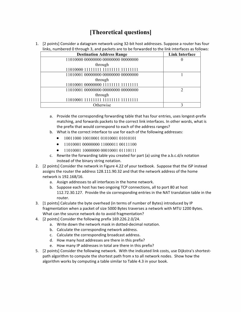
Destination Address Range Link Interface 11010000 00000000 00000000 00000000
through 11010000 11111111 11111111 11111111
0
11010001 00000000 00000000 00000000 through
11010001 00000000 11111111 11111111
1
11010001 00000000 00000000 00000000 through
11010001 11111111 11111111 11111111
2
Otherwise 3
a. Providethecorrespondingforwardingtablethathasfourentries,useslongest-prefixmatching,andforwardspacketstothecorrectlinkinterfaces.Inotherwords,whatistheprefixthatwouldcorrespondtoeachoftheaddressranges?
c. DescribehowTailDropbuffermanagementcanbedetrimentaltoapplicationperformanceanddiscussadvancedtechniquestosolvethisproblemfollowingourdiscussionof[Floyd+93,RandomEarlyDetection].
Wireshark Lab: IP
In this lab, we’ll investigate the IP protocol, focusing on the IP datagram. We’ll do so by analyzing a trace of IP datagrams sent and received by an execution of the traceroute program. We’ll investigate the various fields in the IP datagram, and study IP fragmentation in detail. To best understand and work through this lab, there are a few resources you can take advantage of. Section 1.4.3 in the text and section 3.4 of RFC 2151 [ftp://ftp.rfc-editor.org/in-notes/rfc2151.txt] review the operation of the traceroute program. You should also read Section 4.4 in the text to be sure you understand IP. If you feel that more detail on IP could help, then you should use RFC 791 [ftp://ftp.rfc-editor.org/in-notes/rfc791.txt]. 1. Capturing packets from an execution of traceroute In order to generate the trace of IP datagrams for this lab, the traceroute program was used to send datagrams of different sizes towards some destination, X. Recall that traceroute operates by first sending one or more datagrams with the time-to-live (TTL) field in the IP header set to 1; it then sends a series of one or more datagrams towards the same destination with a TTL value of 2; it then sends a series of datagrams towards the same destination with a TTL value of 3; and so on. A router must decrement the TTL in each received datagram by 1. If the TTL reaches 0, the router returns an ICMP message (type 11 – TTL-exceeded) to the sending host. As a result of this behavior, a datagram with a TTL of 1 (sent by the host executing traceroute) will cause the router one hop away from the sender to send an ICMP TTL-exceeded message back to the sender; the datagram sent with a TTL of 2 will cause the router two hops away to send an ICMP message back to the sender; the datagram sent with a TTL of 3 will cause the router three hops away to send an ICMP message back to the sender; and so on. In this manner, the host executing traceroute can learn the identities of the routers between itself and destination X by looking at the source IP addresses in the datagrams containing the ICMP TTL-exceeded messages. For this lab we’ll investigate the traceroute program by having it send datagrams of various lengths. As with the previous assignments, the trace you will use in Wireshark has been generated for you. However, if you would like to run the traceroute program yourself to experiment with the different options, follow the following instructions.
Note: experimenting with traceroute is OPTIONAL, yet encouraged:
• Windows. The tracert program provided with Windows does not allow one to change the size of the ICMP echo request (ping) message sent by the tracert program. A nicer Windows traceroute program is pingplotter, available both in free version and shareware versions at http://www.pingplotter.com. Download and install pingplotter, and test it out by performing a few traceroutes to your favorite sites. The size of the ICMP echo request message can be explicitly set in pingplotter by selecting the menu item Edit->Advanced Options->Packet Options and then filling in the Packet Size field. The default packet size is 56 bytes. Once pingplotter has sent a series of packets with the increasing TTL values, it restarts the sending process again with a TTL of 1, after waiting Trace Interval amount of time. The value of Trace Interval and the number of intervals can be explicitly set in pingplotter.
• Linux/Unix. With the Unix traceroute command, the size of the UDP datagram sent towards the destination can be explicitly set by indicating the number of bytes in the datagram; this value is entered in the traceroute command line immediately after the name or address of the destination. For example, to send traceroute datagrams of 100 bytes towards gaia.cs.umass.edu, the command would be:
%traceroute gaia.cs.umass.edu 100 The Wireshark trace was captured through the following steps:
• Packet capture with Wireshark was started on a Windows machine. • Three sets of traceroutes were executed. In the first set, three pings with a packet
size of 56 bytes were sent to a destination. In the second set, three pings with a packet size of 2000 bytes were sent to a destination. In the final set, three pings with a packet size of 3500 bytes were sent to a destination.
• If you try this out with the pingplotter on Windows, you will get a screenshot that looks something like this:
2. A look at the captured trace In the trace, you should be able to see the series of ICMP Echo Requests sent by the client computer and the ICMP TTL-exceeded messages returned to the computer by the intermediate routers.
1. Select the first ICMP Echo Request message sent by the client computer, and expand the Internet Protocol part of the packet in the packet details window, as shown in the figure below. You should see something similar to the image above. What is the IP address of the client?
2. Within the IP packet header, what is the value in the upper layer protocol field? What is the purpose of this field?
3. Has this IP datagram been fragmented? Explain how you determined whether or not the datagram has been fragmented.
Next, sort the traced packets according to IP source address by clicking on the Source column header; a small downward pointing arrow should appear next to the word Source. If the arrow points up, click on the Source column header again. Select the first ICMP Echo Request message sent by the client computer, and expand the Internet Protocol portion in the “details of selected packet header” window. In the “listing of captured packets” window, you should see all of the subsequent ICMP messages (perhaps with additional interspersed packets sent by other protocols running on the computer) below this first ICMP. Use the down arrow to move through the ICMP messages sent by the computer.
4. Which fields in the IP datagram always change from one datagram to the next within this series of ICMP messages sent by your computer? Why must those fields change?
5. Describe the pattern you see in the values in the Identification field of the IP datagram.
Fragmentation Sort the packet listing according to time by clicking on the Time column.
6. Find the first ICMP Echo Request message that was sent by the computer after the Packet Size was changed to 2000. How many datagrams has that message been fragmented across?
7. What information in the IP header indicates that the datagram been fragmented? What information in the IP header indicates whether this is the first fragment versus a latter fragment?
8. Now look at the second fragment of the IP datagram. What information in the IP header indicates that this is not the first datagram fragment? Are there more fragments? How can you tell?
Now find the first ICMP Echo Request message that was sent by the computer after the Packet Size was changed to 3500.
9. How many fragments were created from the original datagram? 10. What fields change in the IP header among the fragments?


![PES 1120: Homework assignment 1 [24 points] - UCCS …€¦ · PES 1120: Homework assignment 1 [24 points] Handed out: Friday January 31 Due in: Friday February 7, at the start of](https://static.documents.pub/doc/80x56/5ac7df2b7f8b9a40728c3a4d/pes-1120-homework-assignment-1-24-points-uccs-pes-1120-homework-assignment.jpg)


