IEEE Std C37.013-1997(Revision of IEEE Std C37.013-1993)
IEEE Standard for AC High-Voltage Generator Circuit Breakers Rated on a Symmetrical Current Basis
SponsorSwitchgear Committeeof theIEEE Power Engineering Society
Approved 20 March 1997
IEEE Standards Board
Abstract: Ratings, performance requirements, and compliance test methods are provided for ac high-voltage generator circuit breakers rated on a symmetrical current basis that are installed between thegenerator and the transformer terminals. Guidance for applying generator circuit breakers is given. Pumpedstorage installations are considered a special application, and their requirements are not completelycovered by this standard.Keywords: ac high-voltage generator, application guidance, generator circuit breakers, symmetricalcurrent-rating structure, terminals of large generators, testing procedures
The Institute of Electrical and Electronics Engineers, Inc.
345 East 47th Street, New York, NY 10017-2394, USA
All rights reserved. Published 1997. Printed in the United States of America
ISBN 1-55937-916-2
No part of this publication may be reproduced in any form, in an electronic retrieval system or otherwise, without theprior written permission of the publisher.
ii
IEEE Standards documents are developed within the IEEE Societies and the Standards Coordinating Committees ofthe IEEE Standards Board. Members of the committees serve voluntarily and without compensation. They are notnecessarily members of the Institute. The standards developed within IEEE represent a consensus of the broadexpertise on the subject within the Institute as well as those activities outside of IEEE that have expressed an interestin participating in the development of the standard.
Use of an IEEE Standard is wholly voluntary. The existence of an IEEE Standard does not imply that there are no otherways to produce, test, measure, purchase, market, or provide other goods and services related to the scope of the IEEEStandard. Furthermore, the viewpoint expressed at the time a standard is approved and issued is subject to changebrought about through developments in the state of the art and comments received from users of the standard. EveryIEEE Standard is subjected to review at least every five years for revision or reaffirmation. When a document is morethan five years old and has not been reaffirmed, it is reasonable to conclude that its contents, although still of somevalue, do not wholly reflect the present state of the art. Users are cautioned to check to determine that they have thelatest edition of any IEEE Standard.
Comments for revision of IEEE Standards are welcome from any interested party, regardless of membership affiliationwith IEEE. Suggestions for changes in documents should be in the form of a proposed change of text, together withappropriate supporting comments.
Interpretations: Occasionally questions may arise regarding the meaning of portions of standards as they relate tospecific applications. When the need for interpretations is brought to the attention of IEEE, the Institute will initiateaction to prepare appropriate responses. Since IEEE Standards represent a consensus of all concerned interests, it isimportant to ensure that any interpretation has also received the concurrence of a balance of interests. For this reason,IEEE and the members of its societies and Standards Coordinating Committees are not able to provide an instantresponse to interpretation requests except in those cases where the matter has previously received formalconsideration.
Comments on standards and requests for interpretations should be addressed to:
Authorization to photocopy portions of any individual standard for internal or personal use is granted by the Instituteof Electrical and Electronics Engineers, Inc., provided that the appropriate fee is paid to Copyright Clearance Center.To arrange for payment of licensing fee, please contact Copyright Clearance Center, Customer Service, 222 RosewoodDrive, Danvers, MA 01923 USA; (508) 750-8400. Permission to photocopy portions of any individual standard foreducational classroom use can also be obtained through the Copyright Clearance Center.
Note: Attention is called to the possibility that implementation of this standard may require use of subject mattercovered by patent rights. By publication of this standard, no position is taken with respect to the existence orvalidity of any patent rights in connection therewith. The IEEE shall not be responsible for identifying patents forwhich a license may be required by an IEEE standard or for conducting inquiries into the legal validity or scopeof those patents that are brought to its attention.
iii
Introduction
(This introduction is not a part of IEEE Std C37.013-1997, IEEE Standard for AC High-Voltage Generator Circuit Breakers Ratedon a Symmetrical Current Basis.)
This standard has been revised to clarify the meaning of rated maximum voltage as used in this standard and covers therequirements for ac high-voltage generator circuit breakers as applied directly to the outgoing terminals of generators.The rating, testing, and application requirements of these specialized circuit breakers are not adequately covered by theexisting standards IEEE Std C37.04-1979, ANSI C37.06-1987, IEEE Std C37.09-1979, and IEEE Std C37.010-1979series for ac high-voltage circuit breakers rated on a symmetrical current basis. In order to avoid the detailedintegration and possible confusion by introducing the specialized requirements into the existing standards, it wasdetermined that a separate standard was the most effective method for covering these devices.
A working group of the High-Voltage Circuit Breaker Subcommittee of the IEEE Switchgear Committee has revisedthis standard with input from various sources on all requirements for these specialized devices. The Working Grouphas developed an Application Guide, which is contained in Clause 6. of this standard. The guide is intended to assistthe engineer applying a generator circuit breaker on an electric power system.
These efforts have contributed valuable standards to the industry. Further suggestions for improvement gained fromthe use of this standard will be welcomed.
The Accredited Standards Committee on Power Switchgear, C37, which reviewed this supplement, had the followingmembership at the time of ballot:
E. Byron, Chair A. K. McCabe ( Executive Vice Chair of High-Voltage Switchgear Standards)
J. C. Scott (Executive Vice Chair of Low-Voltage Switchgear Standards)D. L. Swindler (Executive Vice Chair of IEC Activities)
Organization Represented Name of Representative
Electric Light and Power Group/Edison Electric Institute (EEI) G. N. MillerD. E. GaliciaD. G. KomassaJoseph L. KoepfingerJ. H. ProvanzanaT. E. Bruck (Alt)
Institute of Electrical and Electronics Engineers (IEEE) D. SigmonL. R. BeardP. W. DwyerA. MonroeD. F. PeeloS. C. Atkinson (Alt)D. G. Kumbera (Alt)L. V. McCall (Alt)
iv
The Working Group of the High-Voltage Circuit Breaker Subcommittee of the IEEE Switchgear Committee thatrevised IEEE Std C37.013-1997 had the following membership:
E. M. Ruoss, Chair
D. DufournetR. W. Long
N. McCordG. F. Montillet
Y. I. MusaC. L. Wagner
The High-Voltage Circuit Breaker Subcommittee of the IEEE Switchgear Committee that reviewed and approved thisrevised document had the following membership:
S. BernerydJ. H. BrunkeD. R. CrawfordC. J. DvorakP. W. DwyerM. J. EckelkampR. D. GarzonK. I. GrayH. L. HessP. L. KolarikS. KuznetsovG. C. LaguensS. R. Lambert
D. M. LarsonG. N. LesterR. W. LongA. K. McCabeG. J. MeindersG. F. MontilletJ. F. O’DonnellD. E. ParrB. Patel D. F. PeeloG. O. PerkinsJ. E. ReedA. B. Rishworth
H. C. RossE. M. RuossL. R. SaavedraR. A. SarkinenG. E. SeyrlingD. N. SharmaH. M. SmithG. St. JeanD. L. SwindlerT. J. Tobin E. F. VeverkaC. L. Wagner B. F. Wirtz
The following persons were on the balloting committee:
R. W. AlexanderJ. G. AngelisR. H. ArndtC. Ball
L. R. BeardH. L. BowlesM. T. BrownJ. H. Brunke
T. BurseR. L. CapraA. DixonJ. J. Dravis
National Electrical Manufacturers Association (NEMA) E. Byron (Alt)R. GarzonW. KrachtH. L. MillerT. OlsenD. StoneE. Byron (Alt)G. T. Jones (Alt)G. Sakats (Alt)D. L. Swindler (Alt)
Testing Laboratory Group/MET Electrical Testing Association L. Frier
Underwriters Laboratories P. Notarian
Tennessee Valley Authority D. N. Reynolds
US Department of the Army, Office of the Chief of Engineers J. A. Gilson
US Department of the Navy, Naval Construction Battalion Center R. R. Nicholas
Western Area Power Administration G. D. Birney
National Electric Contractors Association (NECA) D. Harwood
Organization Represented Name of Representative
v
C. J. DvorakP. W. DwyerR. D. GarzonK. I. GrayK. D. HendrixH. L. HessJ. M. JerabekP. L. KolarikD. G. KumberaS. R. LambertW. E. LaubachJ. G. LeachG. N. LesterD. L. Lott E. L. LuehringP. C. Mayo
A. K. McCabeL. V. McCallW. C. McKayN. McQuin D. C. MillsA. C. MonroeG. F. MontilletF. MuenchJ. F. O’DonnellR. P. O’LearyA. F. ParksD. F. PeeloG. O. PerkinsR. K. RanjanJ. C. RansomD. N. Reynolds
H. C. Ross T. E. RoysterL. H. SchmidtC. A. SchwalbeD. N. SharmaG. St. JeanA. D. StormsD. L. SwindlerJ. S. TanneryS. H. TelanderF. C. TeufelT. J. TobinE. F. VeverkaC. L. Wagner
When the IEEE Standards Board approved this standard on 20 March 1997, it had the following membership:
Donald C. Loughry, Chair Richard J. Holleman, Vice Chair
Andrew G. Salem, Secretary
Gilles A. BarilClyde R. CampJoseph A. CannatelliStephen L. DiamondHarold E. EpsteinDonald C. FleckensteinJay Forster*Donald N. HeirmanBen C. Johnson
E. G. “Al” KienerJoseph L. Koepfinger*Stephen R. LambertLawrence V. McCallL. Bruce McClungMarco W. MigliaroMary Lou PadgettJohn W. PopeJose R. Ramos
Arthur K. ReillyRonald H. ReimerGary S. RobinsonIngo RüschJohn S. RyanChee Kiow TanLeonard L. TrippHoward L. Wolfman
*Member Emeritus
Also included are the following nonvoting IEEE Standards Board liaisons:
Satish K. Aggarwal Alan H. Cookson Chester C. Taylor
4. Service conditions ...............................................................................................................................................3
4.1 Usual service conditions ............................................................................................................................ 34.2 Unusual service conditions ........................................................................................................................ 44.3 Impact on environment .............................................................................................................................. 4
5. Ratings and required capabilities ........................................................................................................................5
5.1 Rated maximum voltage ............................................................................................................................ 55.2 Power frequency ........................................................................................................................................ 55.3 Rated continuous current ........................................................................................................................... 55.4 Rated dielectric strength............................................................................................................................. 95.5 Rated short-circuit duty cycle .................................................................................................................... 95.6 Rated interrupting time ............................................................................................................................ 105.7 Rated closing time.................................................................................................................................... 105.8 Short-circuit current rating....................................................................................................................... 105.9 Transient recovery voltage (TRV) rating................................................................................................. 135.10 Rated load current switching capability................................................................................................... 145.11 Capacitance current switching capability ................................................................................................ 165.12 Out-of-phase current switching capability ............................................................................................... 165.13 Excitation current switching capability.................................................................................................... 175.14 Rated control voltage ............................................................................................................................... 175.15 Rated mechanism fluid operating pressure .............................................................................................. 185.16 Nameplate markings ................................................................................................................................ 18
Annex A (Informative) Example of the application of a generator circuit breaker ......................................................70
1
IEEE Standard for AC High-Voltage Generator Circuit Breakers Rated on a Symmetrical Current Basis
1. Scope
This standard applies to all ac high-voltage generator circuit breakers rated on a symmetrical current basis that areinstalled between the generator and the transformer terminals. Pumped storage installations are considered a specialapplication, and their requirements are not completely covered by this standard.
NOTE — Since no other national or international standard on generator circuit breakers exists, this standard is used worldwide.The revision of IEEE Std C37.013-1993 takes care of this fact by adapting its content in some places to internationalpractice.
2. References
The standard shall be used in conjunction with the following publications. When the following publications aresuperseded by an approved revision, the revision shall apply.
ANSI C37.06-1987 (R1994), Switchgear: AC High-Voltage Circuit Breakers Rated on a Symmetrical Current Basis—Preferred Ratings and Related Required Capabilities.1
ASME Boiler and Pressure Vessel Code, 1995 Edition.2
IEC 60694: 1996, Common specifications for high voltage switchgear and controlgear standards.
IEEE Std 1-1986 (Reaff 1992), IEEE Standard General Principles for Temperature Limits in the Rating of ElectricalEquipment and for the Evaluation of Electrical Insulation (ANSI).3
1ANSI publications are available from the Sales Department, American National Standards Institute, 11 West 42nd Street, 13th Floor, New York,NY 10036-8002, USA.2ASME publications are available from the American Society of Mechanical Engineers, 22 Law Drive, Fairfield, NJ 07007, USA.3IEEE publications are available from the Institute of Electrical and Electronics Engineers, Service Center, 445 Hoes Lane, P.O. Box 1331,Piscataway, NJ 08855-1331, USA.
IEEE C37.013-1997 IEEE STANDDARD FOR AC HIGH-VOLTAGE GENERATOR
IEEE Std 4-1995, IEEE Standard Techniques for High Voltage Testing (ANSI).
IEEE Std 100-1996, IEEE Standard Dictionary of Electrical and Electronics Terms.
IEEE Std 119-1974, IEEE Recommended Practice for General Principles of Temperature Measurement as Applied toElectrical Apparatus (ANSI/DoD).4
IEEE Std C37.04-1994, IEEE Standard Rating Structure for AC High-Voltage Circuit Breakers Rated on aSymmetrical Current Basis (ANSI).
IEEE Std C37.09-1979 (Reaff 1988), IEEE Standard Test Procedure for AC High-Voltage Circuit Breakers Rated ona Symmetrical Current Basis (ANSI/DoD).
IEEE Std C37.011-1994, IEEE Application Guide for Transient Recovery Voltage for AC High-Voltage CircuitBreakers Rated on a Symmetrical Current Basis (ANSI).
IEEE Std C37.081-1981 (Reaff 1988), IEEE Guide for Synthetic Fault Testing of AC High Voltage Circuit BreakersRated on a Symmetrical Current Basis (ANSI).
IEEE Std C37.082-1982 (Reaff 1988), IEEE Standard Methods for the Measurement of Sound Pressure Levels of ACPower Circuit Breakers (ANSI).
IEEE C37.11-1997, IEEE Standard Requirements for Electrical Control for AC High-Voltage Circuit Breakers Ratedon a Symmetrical Current Basis or a Total Current Basis.
IEEE Std C37.23-1987 (Reaff 1991), IEEE Standard for Metal-Enclosed Bus and Calculating Losses in Isolated-Phase Bus (ANSI).
IEEE Std C37.100-1992, IEEE Standard Definitions for Power Switchgear (ANSI).
IEEE Std C57.13-1993, IEEE Standard Requirements for Instrument Transformers (ANSI).
NEMA MG 1-1993, Motors and Generators.5
NEMA SG 4-1990, Alternating Current High-Voltage Circuit Breaker.
3. Definitions
The definitions of terms contained in this standard, or in other documents referred to in this standard, are not intendedto embrace all legitimate meanings of the terms. They are applicable only to the subject treated in this standard. Foradditional definitions, see IEEE Std C37.100-1992.
A letter symbol (a) indicates that at the time this standard was approved, there was no corresponding definition in IEEEStd C37.100-1992. A letter symbol (b) following the definition indicates that the definition in this standard differs fromthat appearing in IEEE Std C37.100-1992.
3.1 design tests: Those tests made to determine the adequacy of the design of a particular type, style, or modelgenerator circuit breaker to meet its assigned ratings and to operate satisfactorily under usual service conditions or
4IEEE Std 119-1974 has been withdrawn; however, copies can be obtained from Global Engineering, 15 Inverness Way East, Englewood, CO80112-5704, USA, tel. (303) 792-2181.5NEMA publications are available from the National Electrical Manufacturers Association, 1300 N. 17th St., Ste. 1847, Rosslyn, VA 22209, USA.
CIRCUIT BREAKERS RATED ON A SYMMETRICAL CURRENT BASIS IEEE C37.013-1997
under unusual conditions, if specified. Design tests are made only on representative circuit breakers of basically thesame design, i.e., the same interrupters operating at the same contact speeds, and having at least the same dielectricstrength. These tests are not intended to be used as a part of normal production. The applicable portions of these designtests may also be used to evaluate modifications of a previous design and to assure that performance has not beenadversely affected. Test data from previous similar designs may be used for current designs, where appropriate.b
3.2 excitation current switching capability (of a generator circuit breaker): The highest magnetizing current thata generator circuit breaker shall be required to switch at any voltage up to rated maximum voltage at power frequencywithout causing an overvoltage exceeding the levels agreed upon between the user and the manufacturer.a
3.3 generator-source short-circuit current: The short-circuit current when the source is entirely from a generatorthrough no transformation.a
3.4 production tests: Those tests made to check the quality and uniformity of workmanship and materials used in themanufacturing of generator circuit breakers.b
3.5 rated closing time (of a generator circuit breaker): The interval between energizing of the close circuit at ratedcontrol voltage and rated fluid pressure of the operating mechanism and the closing of the main circuit.a
3.6 rated continuous current (of a generator circuit breaker): The designated limit of current in rms amperes atpower frequency that a generator circuit breaker shall be required to carry continuously without exceeding any of itsdesignated limitations.a
3.7 rated interrupting time (of a generator circuit breaker): The maximum permissible interval between theenergizing of the trip circuit at rated control voltage and rated fluid pressure of the operating mechanism and theinterruption of the main circuit in all poles on an opening operation.a
3.8 rated maximum voltage (of a generator circuit breaker): The highest rms voltage for which the circuit breakeris designed, and the upper limit for operation. The rated maximum voltage is equal to the maximum operating voltageof the generator to which the circuit breaker is applied.b
3.9 rated mechanism fluid operating pressure (of a generator circuit breaker): The pressure at which a gas- orliquid-operated mechanism is designed to operate.a
3.10 system-source short-circuit current: The short-circuit current when the source of the short-circuit current isfrom the power system through at least one transformation.a
3.11 tests after delivery: Those tests made by the purchaser after delivery of the circuit breaker, which supplementinspection, to determine whether the circuit breaker has arrived in good condition. These tests may consist of timingtests on closing, opening, close-open no-load operations, and power frequency voltage withstand tests at 75% of therated power frequency withstand voltage.a
4. Service conditions
4.1 Usual service conditions
Generator circuit breakers conforming to this standard shall be suitable for operating at their standard ratings under thefollowing usual service conditions:
a) Ambient temperature for outdoor generator circuit breakers is not above 40 °C or below –30 °C; ambienttemperature for indoor generator circuit breakers is not above 40 °C or below +5 °C.
b) Altitude is not above 1000 m (3300 ft).c) For installations at nuclear power stations, static forces applied to the generator circuit breaker do not exceed
the equivalent force of a 0.5 g acceleration applied horizontally at the center of gravity of the circuit breaker.
IEEE C37.013-1997 IEEE STANDDARD FOR AC HIGH-VOLTAGE GENERATOR
4.2 Unusual service conditions
4.2.1 Abnormal temperatures
The use of apparatus in ambient temperatures outside the limits of those specified in a) of 4.1 shall be considered asspecial.
4.2.2 Altitudes above 1000 m
For applications at altitudes higher than 1000 m, the basic impulse insulation level and rated continuous current shallbe multiplied individually by correction factors in Table 1 to obtain appropriate values.
The rated short-circuit current, related required capabilities, and the rated interrupting time are not affected by altitude.
Table 1— Altitude correction factors
4.2.3 Conditions affecting construction or protecting features
There are application conditions that should receive special consideration. Such conditions should be brought to theattention of those responsible for the application, manufacture, and operation of the equipment.
Apparatus for use in such cases may require special construction or protection. Among such conditions are thefollowing:
a) Exposure to damaging fumes or vapors, excessive or abrasive dust, explosive mixtures of dust or gases,steam, salt spray, oil spray, excessive moisture, dripping water, and other similar conditions;
b) Exposure to abnormal vibration, shock, tilting, or seismic forces;c) Exposure during transportation or storage to conditions beyond temperatures listed in a) of 4.1;d) Unusual space limitations;e) Unusual operating duty, frequency of operation, and difficulty of maintenance;f) Condensation on dielectric surfaces, produced by the generator circuit breaker cooling medium.
4.3 Impact on environment
Generator circuit breakers conforming to this standard shall have limited impact on the environment, as follows:
a) When operated under standard conditions, with all three poles operating simultaneously, the peakinstantaneous sound pressure level of the generator circuit breaker shall be less than 140 dB (unweighted; seeIEEE Std C37.082-1982 )6;
b) The effects of circulating currents induced by magnetic fields produced by continuous currents in thegenerator circuit breaker are addressed in Clause 7.
Altitude (m) Insulation level Rated continuous current
1000 1.00 1.00
1500 0.95 Refer to manufacturer
3000 0.80 Refer to manufacturer
NOTES:1 — Intermediate values can be obtained by interpolation. See example in 7.2.2.2.2 — A revision of the altitude correction factors is under consideration.
6Information on references can be found in Clause 2.
CIRCUIT BREAKERS RATED ON A SYMMETRICAL CURRENT BASIS IEEE C37.013-1997
5. Ratings and required capabilities
The ratings and required capabilities of a generator circuit breaker are the designated limits of operating characteristicsbased on definite conditions and shall include the following items, where applicable:
a) Rated maximum voltage (see 5.1);b) Power frequency (see 5.2);c) Rated continuous current (see 5.3);d) Rated dielectric strength (see 5.4);e) Rated short-circuit duty cycle (see 5.5);f) Rated interrupting time (see 5.6);g) Rated closing time (see 5.7);h) Rated short-circuit current (see 5.8);i) Transient recovery voltage (TRV) rating (see 5.9);j) Rated load current switching capability (see 5.10);k) Capacitance current switching capability (see 5.11);l) Out-of-phase current switching capability (see 5.12);m) Excitation current switching capability (see 5.13);n) Rated control voltage (see 5.14);o) Rated mechanism fluid operating pressure (see 5.15);p) Nameplate markings (see 5.16).
The establishment of the ratings and required capabilities and the assignment of them to a generator circuit breaker inaccordance with these standards implies performance characteristics at least equal to those set forth in 5.1– 5.15. Theratings and required capabilities assigned to a generator circuit breaker are based on test data in accordance withClause 6., but other equivalent or more effective methods of testing are not precluded.
Alternatively, for designs existing prior to the adoption of this standard, the ratings and required capabilities can bebased on other tests that are judged to be equally effective on the basis of the experience gained from previous designor development tests or by service performance experience.
5.1 Rated maximum voltage
The rated maximum voltage of a generator circuit breaker is the highest rms voltage for which the circuit breaker isdesigned and is the upper limit for operation. The rated maximum voltage is equal to the maximum operating voltageof the generator (usually equal to 1.05 times the rated voltage of the generator) to which the circuit breaker is applied.
5.2 Power frequency
The power frequency of a generator circuit breaker is the frequency at which it is designed to operate, with thefrequency being 50 Hz or 60 Hz. Applications at other frequencies should receive special consideration.
5.3 Rated continuous current
The rated continuous current of a generator circuit breaker is the designated limit of current in rms amperes at powerfrequency, which it shall be required to carry continuously without exceeding any of the limitations designated in 5.3.1and 5.3.2. Typical values are 6.3 kA, 8 kA, 10 kA, 12 kA, 16 kA, 20 kA, etc.
5.3.1 Conditions of continuous current rating
The conditions on which continuous current ratings are based are as follows:
IEEE C37.013-1997 IEEE STANDDARD FOR AC HIGH-VOLTAGE GENERATOR
a) Circuit breakers are used under usual service conditions defined in 4.1.b) Current ratings shall be based on the total temperature limits of the materials used for circuit breaker parts. A
temperature rise reference is given to permit testing at reduced ambient temperature.c) Circuit breakers designed for installation in enclosures shall have their ratings based on the ventilation of
such enclosures and on a 40 °C ambient temperature outside the enclosure [see b) in 6.2.1.1].d) Circuit breakers designed for operation with forced air cooling assistance shall have the ratings based on a
40 °C ambient temperature with the forced air cooling system operating.
5.3.2 Temperature limitations for continuous current ratings
5.3.2.1 Limitations on insulating materials
The temperatures of materials used to insulate main power circuit-conducting parts from phase-to-ground or fromterminal-to-terminal of an open circuit breaker shall be limited to the values listed in Table 2. It is recognized that theselimits are generally less than those associated with the insulating class in IEEE Std 1-1986, since such insulation maybe subject to severe mechanical stress when used in a generator circuit breaker.
5.3.2.2 Limitations of main contacts
The temperatures of main contacts used in generator circuit breakers shall not exceed the values listed in Table 3.Contacts may be operated at other temperatures provided it can be shown by experience or tests acceptable to the user,that accelerated deterioration will not occur.
5.3.2.3 Limitations on conducting joints
The temperature of conducting joints in the main power circuit of a generator circuit breaker shall not exceed thevalues listed in Table 3. Conducting joints may be operated at other temperatures provided that experience or testsshow that accelerated deterioration will not occur.
Table 2— Temperature limitations on insulating materials for continuous current ratings
Insulating class of material Main power circuit limits,hottest spot total temperature (°°°°C)
O 90
A 105
B 130
F 155
H 180
C 220
NOTES:1 — See IEEE Std 1-1986 for explanation of insulating classes.2 — If gaseous insulating material is used as conforming to one of the above
classes, the manufacturer shall establish that it will not cause accelerated deterioration of other parts.
CIRCUIT BREAKERS RATED ON A SYMMETRICAL CURRENT BASIS IEEE C37.013-1997
Table 3— Temperature limitations on main contacts and conducting joints for continuous current ratings
5.3.2.4 Limitations for parts subject to contact by personnel
Generator circuit breaker parts handled by the operator in the normal course of work duties shall have no greater a totaltemperature than 50 °C.
Generator circuit breakers having external surfaces accessible to an operator in the normal course of work duties shallhave a total temperature on the surfaces no greater than 70 °C. If the bus duct connected to the generator circuit breakeris designed for a total temperature of 80 °C on the surfaces, then the circuit breaker surface temperature can be 80 °C.
Generator circuit breakers having external surfaces not accessible to an operator in the normal course of work dutiesshall have a total temperature on the surfaces no greater than 110 °C.
5.3.2.5 Limitations on other materials
Other materials shall be chosen so that the maximum temperature to which they may be subjected shall not causeaccelerated deterioration.
5.3.3 Emergency current ratings during loss of cooling
The operating considerations for generator circuit breakers require that emergency ratings are established to enable thecircuit breaker to remain in service following loss of normally required auxiliary forced cooling systems. Thefollowing provisions shall be observed:
a) It is possible to operate the generator circuit breaker for limited time periods with circuit breaker parts at ahigher total temperature than the limits specified for the continuous current rating.
b) The difference between the emergency temperature limits and the normal operating temperatures provide adefinite allowable time period during which full load may be carried before the reduction in load current mustbe accomplished.
c) The generator circuit breaker may remain in service at a reduced load current, the value of which will dependon the type of emergency condition prevailing.
d) Where the circuit breaker continuous current rating is affected by several independent systems (e.g.,interrupting medium, cooling medium, forced air cooling of isolated phase bus, etc.), the effect of losing eachsystem individually and in combination should be established.
e) In addition to a) through d), certain generating station designs (e.g., single generator output connected by twogenerator circuit breakers to two unit step-up transformers) may also require special emergency operatingconditions and ratings.
Factors are illustrated in Figure 1.
Conducting surface Conducting joint surface
Limit of hottest spot temperature rise (°°°°C) at
ambient temperature of 40 °°°°C
Limit of hottest spot total temperature (°°°°C)
Copper 30 70
Silver, silver alloy, or equivalent 65 105
NOTE — If an ambient temperature lower than 40 °C is specified, then the temperature rise can be higher, but the limit of the hottest spot total temperature shall not be exceeded.
IEEE C37.013-1997 IEEE STANDDARD FOR AC HIGH-VOLTAGE GENERATOR
I1 is rated current with all cooling systems in operationI2 is allowable load current if failure (A) of coolant in circuit breaker occursI3 is allowable load current if failure (B) of isolated phase bus cooling air occursI4 is allowable load current if failure (C) of bus and circuit breaker coolant flow occursθmax is allowable hottest spot total temperature in °Cθn is hottest spot total temperature at rated continuous current in °Ct1, t2, t3 are allowable times without a reduction in rated continuous current and without exceeding θmax
Figure 1— Effect of various cooling failures and subsequent load reductions on generator circuit breaker temperature
Figure 1 illustrates typical emergency conditions in which the loss of two cooling systems, that of the generator circuitbreaker and that of the bus duct, have been studied separately and simultaneously.
The following are the parameters that are required for correct operation under each type of emergency condition andfor which values must be determined by the manufacturer:
t1, t2, t3 The time available at rated current before the load must be reduced.R1, R2, R3 The rate at which the load current must be reduced in kA/min.I2, I3, I4 The emergency current assigned to circuit breaker for operating under each emergency condition for a
CIRCUIT BREAKERS RATED ON A SYMMETRICAL CURRENT BASIS IEEE C37.013-1997
5.4 Rated dielectric strength
The rated dielectric strength of a generator circuit breaker is its voltage withstand capability with specified magnitudesand waveshapes. In the event of loss of insulating medium pressure, the generator circuit breaker shall be able towithstand 1.5 times the following voltages:
a) In the open position, the phase opposition voltage across the contacts, the phase-to-ground, and the line-to-line voltage between phases.
b) In the closed position, phase-to-ground and line-to-line voltage between phases. (For applications requiringfull dielectric withstand upon loss of insulating medium, agreement should be reached between the user andthe manufacturer.)
5.4.1 Dielectric strength of external insulation
External insulation shall conform to the performance requirements of this standard. Requirements for the rateddielectric strength of the external insulation of generator circuit breakers are given in Table 4.
Table 4— Schedule of dielectric strength for ac generator circuit breakers and external insulation
5.4.2 Rated power frequency withstand voltage (dry)
The rated power frequency withstand voltage (dry) is the voltage that a new generator circuit breaker must be capableof withstanding for 1 min (see Column 2 of Table 4 and 6.2.2).
5.4.3 Rated full wave impulse withstand voltage
The rated full wave impulse withstand voltage is the crest value of a standard 1.2 × 50 µs impulse voltage wave that anew generator circuit breaker must be capable of withstanding (see Column 3 of Table 4 and 6.2.2).
5.4.4 Rated switching impulse withstand voltage
For generator circuit breakers, the requirements for switching impulse withstand voltage are satisfied by the powerfrequency withstand voltage.
5.5 Rated short-circuit duty cycle
The rated short-circuit duty cycle of a generator circuit breaker shall be two unit operations with a 30 min intervalbetween operations (CO–30 min–CO).
Line Circuit breaker rated maximum voltage kV, rms
IEEE C37.013-1997 IEEE STANDDARD FOR AC HIGH-VOLTAGE GENERATOR
5.6 Rated interrupting time
The rated interrupting time of the generator circuit breaker is the maximum permissible interval between theenergizing of the trip circuit at rated control voltage and rated fluid pressure of the operating mechanism and theinterruption of the main circuit in all poles on an opening operation. Typical values are approximately 60–90 ms withthe actual time being dependent on the rated short-circuit current. For generator circuit breakers equipped withresistors, the interrupting time for the resistor current may be longer.
5.7 Rated closing time
The rated closing time of a generator circuit breaker is the interval between energizing of the close circuit at ratedcontrol voltage and rated fluid pressure of the operating mechanism, and the closing of the main circuit.
5.8 Short-circuit current rating
The short-circuit current rating of a generator circuit breaker is the rms symmetrical component of short-circuit currentto which all required short-circuit capabilities are related. Procedures for determining the symmetrical short-circuitcurrent duties that compare with ratings and related required capabilities are found in Clause 7.
5.8.1 Rated short-circuit current
The rated short-circuit current of a generator circuit breaker is the highest rms value of the symmetrical component ofthe three-phase short-circuit current. It is measured from the envelope of the current wave at the instant of primaryarcing contact separation, and is the current that the generator circuit breaker shall be required to interrupt at the ratedmaximum voltage and rated duty cycle when the source of the short-circuit current is from the power system throughat least one transformation. It establishes also, by ratios defined in 5.8.2.6, the highest current that the generator circuitbreaker shall be required to close and latch against and to carry. Typical values are 63 kA, 80 kA, 100 kA, 120 kA, 160kA, etc.
NOTE — The rare cases when the generator-source short-circuit current is higher than the system source short circuit current needspecial consideration.
5.8.2 Related required capabilities
The generator circuit breaker shall have the following related required capabilities, which are based on the minimumtime to primary arcing contact separation including a relay time of 1/2 cycle, but may be used with any relay time.
5.8.2.1 Required symmetrical interrupting capability for three-phase faults
For three-phase faults, the required symmetrical interrupting capability of a generator circuit breaker at the instant ofprimary arcing contact separation for operating voltages equal to rated maximum voltage shall not exceed the ratedshort-circuit current for the rated duty cycle irrespective of the direct current component of the total short-circuitcurrent.
5.8.2.2 Required asymmetrical interrupting capability for three-phase faults
The required asymmetrical system-source interrupting capability of a generator circuit breaker at rated maximumvoltage and for the rated duty cycle is composed of the rms symmetrical current and the percentage dc component. Thevalues of the dc component in percent of the peak value of the symmetrical short-circuit current are given in Figure 2for primary arcing contact parting times in milliseconds. This figure is based on a time constant of the decay of the dccomponent of 133 ms, which is considered to be conservative. For time constants different than 133 ms, use theformula for calculating the dc component given in 7.3.5.3.2.
CIRCUIT BREAKERS RATED ON A SYMMETRICAL CURRENT BASIS IEEE C37.013-1997
Figure 2— Asymmetrical interrupting capability: DC component in percentage of the peak value of the symmetrical three-phase system-source short-circuit current
The primary arcing contact parting time shall be considered equal to the sum of 1/2 cycle (present practical minimumtripping delay) plus the minimum opening time of the particular generator circuit breaker.
5.8.2.3 Required generator-source symmetrical interrupting capability for three-phase faults
No specific rating is assigned to cover the generator-source short-circuit current because its maximum value is usuallyless than the short-circuit current from the power system. If a rating is assigned, then the generator circuit breaker shallbe tested for the following related capabilities. For three-phase faults, the required generator-source symmetricalinterrupting capability of a generator circuit breaker is the highest value of the symmetrical component of the short-circuit current, measured from the envelope of the current wave at the instant of primary arcing contact separation thatthe generator circuit breaker shall be required to interrupt, at rated maximum voltage and rated duty cycle when thesource of the short-circuit current is entirely from a generator through no transformations.
IEEE C37.013-1997 IEEE STANDDARD FOR AC HIGH-VOLTAGE GENERATOR
5.8.2.4 Required generator-source asymmetrical interrupting capability for three-phase faults
For three-phase faults, the required asymmetrical generator-source interrupting capability of a generator circuitbreaker at rated maximum voltage and for the rated duty cycle is composed of the rms generator-source symmetricalcurrent and a dc component. The value of the dc component is 110% of the peak value of the symmetrical generator-source short-circuit current for all generator circuit breaker primary arcing contact parting times. The primary arcingcontact parting time shall be considered equal to the sum of 1/2 cycle plus the minimum opening time of the particulargenerator circuit breaker.
5.8.2.4.1 Required generator-source asymmetrical interrupting capability for maximum required degree of asymmetry
The maximum required degree of asymmetry of the current for the condition of maximum required degree forasymmetry is 130% of the peak value of symmetrical current for this condition. The symmetrical component of theshort-circuit current under the condition of maximum degree of asymmetry is only 74% of the value of the requiredgenerator-source symmetrical interrupting capability.
5.8.2.5 Required interrupting capability for single-phase-to-ground faults
Generator circuit breakers are designed for use on high-impedance grounded systems where the single phase-to-ground short-circuit current will not exceed 50 A. In no case are the capabilities for single phase-to-ground faultsrequired to exceed this value.
5.8.2.6 Required closing, latching, and carrying capabilities
The generator circuit breaker shall be capable of the following:
a) Closing and latching any power frequency-making current (50 Hz or 60 Hz) whose maximum crest (peakmaking current) does not exceed 2.74 times the rated symmetrical short-circuit current or the maximum crest(peak making current) of the generator-source short-circuit current, whichever is higher. No numerical valuecan be given for the peak value of the generator-source peak current since it depends on the generatorcharacteristic data (see 5.8.2.3 and A.3.2).
b) Carrying the short-circuit current for a time of 0.25 s.
The generator circuit breaker shall be capable of carrying for Ts equals 1 s, any short-circuit current determined fromthe envelope of the current wave at the time of the maximum crest, whose value does not exceed 2.74 times the ratedshort-circuit current, and whose rms value I determined over the complete 1 s period does not exceed the rated short-circuit current considered above.
The mathematical expression for the rms value I of a short-circuit current over the period Ts is as follows:
where
i is the instantaneous current in amperes (see Clause 7. of IEEE Std C37.09-1979) t is the time in seconds
It is not to be inferred that the generator circuit breaker is to be capable of interrupting after the required short-timecurrent-carrying capability duty until it has cooled down to normal heat run temperature.
CIRCUIT BREAKERS RATED ON A SYMMETRICAL CURRENT BASIS IEEE C37.013-1997
5.8.3 Interrupting performance
5.8.3.1 Rated performance
A generator circuit breaker shall perform at or within its rating without producing any injurious emissions.
5.8.3.2 Service capability duty requirements
Generator circuit breakers shall be capable of the following performances under short-circuit and load currentinterruption conditions:
a) One short-circuit duty cycle (CO–30 min–CO).b) A number of load current interruptions in which the sum of the currents interrupted does not exceed 5000%
of rated continuous current of the generator circuit breaker. The number of operations used to make up the5000% is cumulative over a period of time and is a measure of the generator circuit breaker’s reliability anda guide to maintenance. Thermal limitations of parts, such as opening resistors, require that the number ofopening operations comprising the 5000% shall not exceed two in 30 min or four in 4 h.
5.9 Transient recovery voltage (TRV) rating
At its rated maximum voltage, each generator circuit breaker must be capable of interrupting three-phase groundedfaults at rated short-circuit current in any circuit in which the three-phase grounded circuit TRV does not exceed therated TRV envelope.
Each TRV rating is for a three-phase generator circuit breaker. It is not required that a single phase of a generatorcircuit breaker interrupt a single-phase circuit that produces a circuit TRV equal to the rated TRV envelope.
However, as discussed in 6.2.3.8, the single-phase test at 1.5 times phase-to-ground voltage is given as one of the basicapproaches to demonstrating the rating in a design test. It is an optional design test, not a rating requirement.
5.9.1 Rated inherent TRV
The rated inherent TRV shall be defined by an oscillatory waveshape having a TRV rate, time delay, and crest voltage(E2) as listed in Tables 5–6. The formula and method for determining the time-to-crest (T2) are given in 7.3.6.3 andFigure 15.
IEEE C37.013-1997 IEEE STANDDARD FOR AC HIGH-VOLTAGE GENERATOR
Table 5— TRV parameters for system-source faults
Table 6— TRV parameters for generator-source faults
5.9.2 First-pole-to-clear factor
The first-pole-to-clear factor shall be 1.5.
5.9.3 Amplitude factor
The amplitude factor shall be 1.5.
5.10 Rated load current switching capability
The operation endurance capabilities specified in Table 7 are the type and number of complete closing-openingoperations that the generator circuit breaker shall be capable of performing at any voltage up to the rated maximumvoltage under the following conditions:
a) The generator circuit breaker shall operate with rated control voltage and rated fluid (gas or liquid) pressurein the operating mechanism.
b) The frequency of operations is not to exceed two in 30 min and four in 4 h because the generator circuitbreaker may be equipped with auxiliary devices, such as resistors, that have thermal limitations. Whenauxiliary devices such as resistors are not used, the manufacturer may provide alternate frequency ofoperation values.
Transformer rating MVA
T2 in µµµµs Inherent TRV
E2-crest voltage TRV rate kV/µµµµs
100 or less 0.62 V 1.84 V 3.5
101–200 0.54 V 1.84 V 4.0
201–400 0.48 V 1.84 V 4.5
401–600 0.43 V 1.84 V 5.0
601–1000 0.39 V 1.84 V 5.5
1001 or more 0.36 V 1.84 V 6.0
NOTES:1 — Time delay shall be equal to or less than 1 µs.2 — V is the rated maximum voltage in kV.
Generator rating MVA T2 in µµµµs Inherent TRV
E2-crest voltage TRV rate kV/µµµµs
100 or less 1.35 V 1.84 V 1.6
101–400 1.20 V 1.84 V 1.8
401–800 1.08 V 1.84 V 2.0
801 or more 0.98 V 1.84 V 2.2
NOTES:1 — Time delay shall be equal to or less than 0.5 µs.2 — V is the rated maximum voltage in kV.
CIRCUIT BREAKERS RATED ON A SYMMETRICAL CURRENT BASIS IEEE C37.013-1997
c) The values listed in the rating tables have been established by experience and engineering judgment. Thoseinvolving currents are derived from service capability and circuit breaker condition (see 5.8.3.2) and are notseparate ratings (see 6.2.8.2.)
5.10.1 Inherent TRV
The inherent TRV for a load switching operation shall be defined by an oscillatory waveshape having a TRV rate andtime delay as listed in Table 8. The formula and method for determining the time-to-crest (T2) are given in 7.3.6.3 andFigure 15.
5.10.2 Amplitude factor
The amplitude factor shall be 1.5.
Table 7— Operation endurance capabilities for generator circuit breakers
Circuit breaker ratings Number of operations (operation = 1 closing + opening)
Between servicing (see NOTE 2)
No-load mechanical (see NOTES 2–8)
Continuous current switching (see NOTES 2, 4, 5, 7, 8, and 9)
Column 1 Column 2 Column 3 Column 4
Up to 38 kV 500 1000 50
NOTES:1 — The integrated duty on the generator circuit breaker must be within the service capability as defined in 5.8.3. See
Clause 6..
2 — Maintenance consists of cleaning, tightening, adjusting, lubricating, and dressing of contacts, etc., as recommended by the manufacturer under usual service conditions. Maintenance intervals are usually based on both an elapsed time and a number of operations, whichever occurs sooner. In determining maintenance intervals for particular applications, consideration must be given to actual conditions prevailing at the installation site. Refer to Clause 4. for service conditions and to Clause 7. for general application conditions. The number of operations specified in Column 2 are based on usual service conditions. When used as a guide for field application, they define maximum maintenance intervals.
3 — When closing and opening no-load.
4 — With rated control voltage applied (see Table 10).
5 — Frequency of operation (see 5.10).
6 — Requirements are based on specified maintenance intervals in accordance with Column 2.
7 — No functional part shall have been replaced prior to completion of the specified number of operations.
8 — After completion of the specified number of operations, the circuit breaker shall withstand 75% of its rated power frequency withstand voltage, and the resistance of the current carrying circuit from terminal to terminal measured with a current of at least 100 A flowing shall not be increase by more then the amount specified by the manufacturer compared to the value for the circuit breaker when new. Under these conditions, the circuit breaker is considered capable of carrying the rated continuous current, at power frequency, without injurious heating until maintained and of performing one interruption at rated short-circuit current or a related capability. After completion of this series of operations, functional part replacement and general maintenance may be necessary (see 6.2.8.3).
9 — If a short-circuit operation occurs before the completion of the listed operations, maintenance is recommended and possible functional part replacement may be necessary depending on previous duty, fault magnitude, and expected future operations.
IEEE C37.013-1997 IEEE STANDDARD FOR AC HIGH-VOLTAGE GENERATOR
Table 8— TRV parameters for load current switching
5.11 Capacitance current switching capability
This is a special case where the line or bus capacitance is separated from the generator circuit breaker throughtransformation. If this capability is required, the user should consult the manufacturer.
5.12 Out-of-phase current switching capability
This capability applies to a generator circuit breaker used for switching the connection between two parts of a three-phase system during out-of-phase conditions. The generator circuit breaker may be assigned an out-of-phase currentswitching rating when its out-of-phase current switching capability has been demonstrated by the tests specified inClause 6. Other equivalent or more effective methods of test are not precluded.
5.12.1 Assigned out-of-phase current switching rating
The assigned out-of-phase current switching rating is the maximum out-of-phase current that the generator circuitbreaker shall be capable of switching at an out-of-phase recovery voltage equal to that specified in 6.2.9.2 and underprescribed conditions.
5.12.2 Interrupting time for out-of-phase current switching
The interrupting time for out-of-phase current switching is equal to the rated interrupting time.
5.12.3 Inherent TRV for out-of-phase current switching
The inherent TRV for out-of-phase current switching shall be defined by an oscillatory waveshape having the TRVrate, time delay, and crest voltage (E2) as listed in Table 9 (see also 7.3.9.2). The formula and method for determiningthe time-to-crest (T2) are given in 7.3.6.3 and Figure 15.
Generator rating MVA T 2 in µµµµs Inherent TRV
E2-crest voltage TRV rate kV/µµµµs
100 or less 1.08 V 0.92 V 1.0
101– 400 0.91 V 0.92 V 1.2
401– 800 0.77 V 0.92 V 1.4
801 or more 0.62 V 0.92 V 1.6
NOTES:1 — Time delay shall be equal to or less than 1 µs.
CIRCUIT BREAKERS RATED ON A SYMMETRICAL CURRENT BASIS IEEE C37.013-1997
Table 9— TRV parameters for out-of-phase current switching
5.13 Excitation current switching capability
The excitation current switching capability is the highest magnetizing current that a generator circuit breaker shall berequired to switch at any voltage up to rated maximum voltage at power frequency without causing an overvoltageexceeding the levels agreed upon between the user and the manufacturer. This capability may be determined by testsin accordance with 6.2.11.
5.14 Rated control voltage
The rated control voltage of a generator circuit breaker is the designated voltage that is to be applied to the closing ortripping devices to close or open the generator circuit breaker (see Table 10). Other control voltages may be specifiedaccording to other national or international standards depending on the point of original installation.
The transient voltage in the entire control circuit, due to interruption of control circuit current, shall be limited to 1500V crest.
NOTE — The control voltage is allowed to vary above and below its rated value within a specified range (see Table 10). Thecontrol voltage is measured at the terminals of the operating coils with the operating current flowing. The maximumvoltage is measured at the control power terminals of the operating mechanism at no-load and the minimum voltage ismeasured with the maximum operating current flowing. Rated voltages and their permissible ranges for the controlpower supply of generator circuit breakers shall be as shown in Table 10.
Generator rating MVA T2 in µµµµs Inherent TRV
E2-crest voltage TRV rate kV/µµµµs
100 or less 0.89 V 2.6 V 3.3
101– 400 0.72 V 2.6 V 4.1
401– 800 0.63 V 2.6 V 4.7
801 or more 0.57 V 2.6 V 5.2
NOTES:1 — Time delay shall be equal to or less than 1 µs.2 — V is the rated maximum voltage in kV.
IEEE C37.013-1997 IEEE STANDDARD FOR AC HIGH-VOLTAGE GENERATOR
Table 10— Rated control voltages and their ranges for generator circuit breakers
5.15 Rated mechanism fluid operating pressure
The rated mechanism fluid operating pressure of a generator circuit breaker is the pressure at which a gas- or liquid-operated mechanism is designed to operate. The pressure is allowed to vary above and below its rated value within aspecified range.
5.16 Nameplate markings
The following minimum data, when applicable, shall appear on the nameplates of each generator circuit breaker andassociated device.
Direct current voltage ranges (see NOTES 1, 2, 3, 4, 7, 8) closing and auxiliary functions
Alternating current voltage ranges (see NOTES 1, 2, 3, 4, 7, 8)
Rated voltage Indoor circuit
breakers
Outdoor circuit
breakers
Tripping functions (all types)
Rated voltage (60 Hz)
Closing, tripping, and auxiliary functions
24 (see NOTE 5) — — 14–28 Single phase
48 (see NOTE 5) 38–56 36–56 28–56 120 104–127 (see NOTE 6)
125 100–140 90–140 70–140 240 208–254 (see NOTE 6)
250 200–280 180–280 140–280 Three-phase
208 Y/120 180 Y/104–220 Y/127
240 208–254
NOTES:1 — Relays, motors, or other auxiliary equipment that function as part of the control for a device shall be subject to
the voltage limits imposed by this standard, whether mounted at the device or at a remote location.
2 — Mechanism devices in some applications may be exposed to control voltages exceeding those specified here due to abnormal conditions, such as abrupt changes in line loading. Such applications require study, and the manufacturer should be consulted. Also, application of switchgear devices containing solid-state control exposed continuously to control voltages approaching the upper limits of ranges specified herein require specific attention, and the manufacturer should be consulted before application is made.
3 — Includes supply for pump or compressor motors. Note that rated voltages for motors and their operating ranges are covered in NEMA MG 1-1993.
4 — It is recommended that the coils of closing, auxiliary, and tripping devices that are connected continually to one dc potential should be connected to the negative control bus so as to minimize electrolytic deterioration.
5 — 24 V and 48 V tripping, closing, and auxiliary functions are recommended only when the device is located near the battery or where special effort is made to ensure the adequacy of conductors between battery and control terminals. 24 V closing is not recommended.
6 — Includes heater circuits.
7 — Extended voltage ranges apply to all closing and auxiliary devices when cold. Mechanisms utilizing standard auxiliary relays for control functions may not comply at lower extremes of voltage ranges when relay coils are hot, as after repeated or continuous operation.
8 — DC control voltage sources, such as those derived from rectified alternating current, may contain sufficient inherent ripple to modify the operation of control devices to the extent that they may not function over the entire specified voltage ranges.
CIRCUIT BREAKERS RATED ON A SYMMETRICAL CURRENT BASIS IEEE C37.013-1997
5.16.1 Circuit breaker
The following circuit breaker and operating mechanism nameplates may be combined:
a) Manufacturer’s name;b) Manufacturer’s type designation;c) Manufacturer’s serial number (limited to 15 letters or numbers);d) Year of manufacture;e) Power frequency (Hz);f) Rated continuous current (kA);g) Rated maximum voltage (kV);h) Rated full-wave impulse withstand voltage (kV peak);i) Rated short-circuit duty cycle;j) Rated short-circuit current (symmetrical, kA);k) DC component in percentage of the peak value of the rated short-circuit current;l) Close, latch and carry current (kA peak);m) Short-time current (kA for 1 s);n) Assigned out-of-phase switching current (kA);o) Rated interrupting time (ms);p) Rated insulating medium pressure or density at 20 °C;q) Forced cooling: kind, pressure, temperature, quantity (if applicable);r) Instruction book number;s) Renewal parts catalog;t) Weight of circuit breaker.
5.16.2 Operating mechanism
The following operating mechanism and circuit breaker nameplates may be combined:
a) Manufacturer’s name;b) Manufacturer’s type designation;c) Manufacturer’s serial number;d) Year of manufacture;e) Rated control voltage for closing coil;f) Rated control voltage for tripping coil;g) Rated control voltage for motors and pumps;h) Closing current;i) Tripping current;j) Current for motors and pumps;k) Rated fluid pressure or density at 20 °C;l) Instruction book number.
5.16.3 Accessories
Nameplates of all accessories shall include the following:
a) Identification;b) Pertinent operating characteristics.
5.16.4 Modernization of circuit breakers
Revised nameplates shall be furnished when modernization is involved. IEEE Std C37.59-1996 [B5] may be consultedif desired.
IEEE C37.013-1997 IEEE STANDDARD FOR AC HIGH-VOLTAGE GENERATOR
5.16.5 Instruction and warning signs
Essential markings shall be provided for instruction and warning signs as follows:
a) Identify operating devices and positions;b) Give pertinent instructions for operation;c) Call attention to special precautions.
6. Tests
6.1 General
The test procedure summarizes the various tests that are made on ac high-voltage generator circuit breakers, describesaccepted methods used in making the tests, and specifies the tests that will demonstrate ratings under IEEE/ANSIstandards. It does not preclude the use of other equivalent or more effective methods of demonstrating ratings. Thetests are divided into the following classifications:
a) Design tests;b) Production tests;c) Tests after delivery.
6.2 Design tests
The design tests described in this test procedure provide methods of demonstrating the ability of a generator circuitbreaker to meet the assigned ratings when operating at rated maximum voltage and power frequency. The electricaland mechanical endurance tests shall be made with generator circuit breakers of the same type.
6.2.1 Rated continuous current-carrying tests
Rated continuous current-carrying tests demonstrate that the generator circuit breaker can carry its rated continuouscurrent at its power frequency without exceeding any of the temperature limitations in 5.3.2.
6.2.1.1 Conditions of test
a) The ambient temperature shall be between 10 °C and 40 °C inclusive, so that no correction factors need beapplied.
b) The circuit breaker shall be tested indoors under usual service conditions. Enclosed generator circuit breakersshall be tested in their enclosures.If an isolated phase bus is used and is forced air-cooled, tests shall be conducted with the air quantity (m3/sec)and air entrance temperature of the most unfavorable phase.If there is no forced air-cooling of the isolated phase bus, the connections of the generator circuit breaker tothe isolated phase bus shall be such that no significant amount of heat is conducted away from or conveyed tothe generator circuit breaker during the tests. The temperature rise at the terminals of the generator circuitbreaker live parts and at the encapsulation at a distance of 1 m from the generator circuit breaker terminalsshall be measured. The difference in the two temperature rises shall not exceed 5 °C. The type and size of theconnection between the generator circuit breaker and the isolated phase bus shall be recorded in the testreport.If other coolants are used (water, etc.), the coolant quantity and entrance temperature shall be adjusted to theprevailing rated service conditions.
CIRCUIT BREAKERS RATED ON A SYMMETRICAL CURRENT BASIS IEEE C37.013-1997
Other apparatus incorporated in series and closely associated with the generator circuit breaker, such ascurrent transformers, primary disconnecting contacts, buses, and the connections shall be mounted in theirregular positions.
c) Indoor or outdoor generator circuit breakers, which are normally installed in such a manner that otherconnected apparatus has no appreciable effect on the generator circuit breaker temperature, shall be testedwith parts of the isolated phase bus of a size corresponding to the current rating of the generator circuitbreaker, connected to the circuit breaker terminals by means of typical terminal connectors of correspondingcurrent rating or by other means that shall be evaluated as equivalent for the specific application.
d) In cases where the enclosure carries a current approximately equal to the rated continuous current, the returnpath during the test shall be the enclosure. The generator circuit breaker enclosure shall be made airtightwhen a bus duct forced air cooling system is part of the design.
6.2.1.2 Test procedure
Testing of generator circuit breakers often places special demands on the testing laboratories not only because of thehigh continuous current and short-circuit current ratings of the circuit breakers, but also because of their metal-enclosed design that allows them to be connected directly to metal-enclosed bus duct. In cases where the prescribedtesting procedures will be difficult to meet, the test circuits and the test conditions shall take into account the practicalapplication of the circuit breaker in the power system and also the conditions at the test laboratory. Three-phasegenerator circuit breakers shall be tested three-phase except in the following cases:
a) Where there is no possibility of magnetic or thermal influence between poles or modular units, single-phasetests may be made on a single-pole or modular unit;
b) Where there is no possibility of magnetic influence, but there may be thermal influence from other phases ofthe circuit breaker, tests may be made with single-phase current passed through the three poles in series;
c) Where test stations have inadequate energy levels, single-phase tests may be made.
The continuous current-carrying capability of the generator circuit breaker is influenced by the temperature of theconnected isolated phase bus. This situation must be taken into account when performing heat run tests. Thetemperatures of the isolated phase buses measured at a distance of 1 m from the generator circuit breaker shall beagreed upon by the user and the manufacturer, and shall be specified in the type test report.
When testing a generator circuit breaker with a forced-cooled rating, the continuous current-carrying capability shallbe determined with and without the forced cooling. The temperatures in the current-carrying path shall be measuredduring these tests. If the forced-cooling systems of the bus duct and the generator circuit breaker use the same air, thephenomenon becomes complicated when the cooling air is lost. The temperature of the bus duct does not remainconstant but will also rise, and this rise must be taken into account during testing. The limit of total temperature of thebus duct has to be agreed upon by the user and the manufacturer, and the practical application in the power system hasto be taken into account as well in order to carry out realistic tests.
6.2.1.3 Duration of rated continuous current test
The test shall be made over a period of time sufficient for the temperature rise to stabilize. This condition is usuallyreached when the increase in temperature rise of that generator circuit breaker live part with the highest temperaturelimit does not exceed 1 °C in 1 h. The time for the entire test may be shortened by preheating the generator circuitbreaker with a higher value of current, unless a measurement of thermal time constant is required.
6.2.1.4 Temperature measurement
Temperatures shall be measured by the following methods (see IEEE Std 119-1974 ):
a) Thermocouple.b) Thermometer. This is the preferred method for ambient temperatures.
IEEE C37.013-1997 IEEE STANDDARD FOR AC HIGH-VOLTAGE GENERATOR
c) Infrared cameras or heat-sensitive devices. Use of bolometers, infrared devices, or other temperature-measuring systems able to measure the temperature inner or outer parts of the generator circuit breaker bymeans of a viewport are acceptable provided that the tolerance of the measurement is within the acceptedgeneral limits (less than 0.5 °C).
d) Location of measuring devices. The measuring device shall be located where measurement of the hottest spotcan be made even though it may involve drilling holes that destroy some parts on a design test. This willrequire the use of thermocouples in locations inaccessible to thermometers in order to obtain the hottest spotmeasurement. It is recognized that thermocouples cannot be located in the actual contact point of line or pointcontacts without destroying the effectiveness of such line or point contacts.
Measurements shall be made at junction points of insulation and conducting parts to prevent exceeding temperaturelimits of the insulation. Thermocouples shall be located so as to obtain the hottest spot measurement. For site tests, ifrequired, it is sufficient to measure accessible parts and compare the measurements with like points on the design tests.Holes that destroy the effectiveness of the test (such as in multiturn coils) shall not be drilled.
6.2.1.5 Determination of ambient temperature
The ambient temperature shall be taken as that of the air surrounding the test circuit breaker. The ambient temperatureshall be 10– 40 °C inclusive, so that no correction factors need be applied.
The ambient temperature shall be determined by taking the average of the readings of three thermometers placed inlocations unaffected by drafts, horizontally 1000 mm from the projected periphery of the circuit breaker or enclosure,and approximately on a vertical line according to the following:
a) One approximately 1000 mm above the circuit breaker or enclosure (including bushings).b) One approximately 1000 mm below the circuit breaker or enclosure. (In the case of floor-mounted circuit
breakers or enclosures, it shall be 1000 mm above the floor or mounting base.)c) One approximately midway between the above two positions.
In order to avoid errors due to the time lag between the temperature of large apparatus and the variations in the ambienttemperature, all reasonable precautions must be taken to reduce these variations and the errors arising from them.Thus, the thermometer for determining the ambient temperature shall be immersed in a suitable heavy metal oil cupwhen the ambient temperature is subject to such variations.
A convenient form for such an oil cup consists of a metal cylinder with a hole drilled partly through it. This hole isfilled with oil, and the thermometer is placed in it with its bulb well immersed. The response of the thermometer tovarious rates of temperature change will depend largely on the size, kind of material, and mass of the containing cup,and may be further regulated by adjusting the amount of oil in the cup. The larger the apparatus under test, the largerthe metal cylinder that shall be used as an oil cup in determining the cooling air temperature. The smallest size oil cupused in any case shall be a metal cylinder 25 mm in diameter and 50 mm high.
6.2.1.6 Demonstrations of emergency conditions
Emergency conditions can be demonstrated by tests. These tests shall include, if applicable, but are not limited to, thefollowing simulations:
a) Loss of cooling fluid.b) Loss of insulating medium.c) Failure of the cooling system, subdivided partially, if applicable, into fans, pumps, air circulators, or any other
means of cooling applicable to the specific apparatus being tested. Failure of each cooling subsystem shall besimulated individually and simultaneously.
d) Failure of air cooling in the isolated phase bus.
All the above losses and failures shall be simulated individually and simultaneously.
CIRCUIT BREAKERS RATED ON A SYMMETRICAL CURRENT BASIS IEEE C37.013-1997
For each type of failure, the following data shall be noted:
1) Maximum tolerable temperature limit to be determined by the manufacturer;2) Maximum time the emergency condition can persist in order not to exceed the maximum tolerable
temperature limit (t1, t2, etc.);3) A rate of decrease of the continuous current (R1, R2, etc.);4) A stabilization of the continuous current at a lower value such that the maximum temperature rise in the
circuit breaker will be in accordance with 5.3.3 (I1, I2, etc.).
It is suggested that data for the rate of decrease of the current, the emergency condition, and its duration, etc., bepresented graphically by the manufacturer as illustrated in Figure 1.
6.2.2 Rated dielectric strength
The dielectric strength of a generator circuit breaker is demonstrated by subjecting it to high voltages, both powerfrequency and impulse based on its rated maximum voltage.
Metal enclosed generator circuit breakers shall be tested in their enclosures. If current transformers, groundingswitches, or other equipment is integrated in the design of the generator circuit breaker, the dielectric tests shall bemade with this equipment included. Dielectric tests shall be made at minimum insulating fluid pressure.
It may be difficult to carry out the dielectric tests on generator circuit breakers equipped with resistors or capacitorsthat influence the inherent TRV. In such cases, they can be removed if they consume too much of the energy of the testcircuit (e.g., due to capacitors when impulse testing or due to resistors during power frequency tests).
Withstand tests on generator circuit breakers shall be made at the factory under temperature and humidity conditionsnormally occurring during commercial testing. The generator circuit breaker shall be clean and in good condition andshall not have been put into commercial operation. Values for correction factors for atmospheric pressure andatmospheric humidity for impulse and power frequency tests are to be from IEEE Std 4-1995.
When refinements in correction factors in IEEE Std 4-1995 are made, it shall not be necessary to repeat design tests ondesigns for which such tests have been completed. Correction factors shall not be used on power frequency dry tests.
Generator circuit breakers with integrated series isolators may have a movable insulating barrier that can be closed ifrequired in the isolator-open position as an additional protective measure to separate the generator circuit breaker’senergized and de-energized parts. Tests on such generator circuit breakers shall be made with the barrier in both theopen and closed position.
If liquid coolants circulate under normal service conditions between the generator circuit breaker’s energized andgrounded parts, the tests shall be made with the coolant circulating and with maximum coolant conductivity permittedby the manufacturer.
6.2.2.1 Rated power frequency withstand voltage (dry)
Tests are made to determine the ability of the generator circuit breaker to withstand the rated power frequencywithstand voltage (see 5.4). The frequency of the power frequency test voltage shall be within ± 20% of the powerfrequency of the apparatus tested. The waveshape should be as close to a sine wave as practicable. The test shall bemade with alternating voltage having a crest value equal to times the rated power frequency withstand voltage. Inthese tests, an alternating voltage shall be applied to the terminals of the generator circuit breaker for 1 min, withoutdamage or flashover, in each of the following methods:
a) With the generator circuit breaker in the open position, apply power frequency voltage to each terminal of thegenerator circuit breaker individually, with all other terminals and enclosures of the generator circuit breakergrounded;
IEEE C37.013-1997 IEEE STANDDARD FOR AC HIGH-VOLTAGE GENERATOR
b) With the generator circuit breaker contacts closed, apply power frequency voltage to each phase of thegenerator circuit breaker individually, with the enclosure of the generator circuit breaker grounded;
c) Tests shall be performed with the insulating medium at atmospheric pressure to simulate the loss of thismedium and with a voltage corresponding to 1.5 times the phase opposition voltage (see 5.4).
6.2.2.2 Rated full wave impulse withstand voltage
Tests under dry conditions are made on generator circuit breakers to determine their ability to withstand their rated fullwave impulse withstand voltages.
In these tests, both positive and negative impulse voltages, having a crest value equal to the rated full wave impulsewithstand voltage of the generator circuit breaker and a waveshape of 1.2 × 50 µs, shall be applied to the terminals ofthe generator circuit breaker without damage or flashover in each of the following methods:
a) With the generator circuit breaker in open position:1) Apply positive impulse voltage three consecutive times without flashover to each terminal of the circuit
breaker individually, with all other terminals and enclosures grounded;2) Apply negative impulse voltage three consecutive times without flashover to each terminal of the circuit
breaker individually, with all other terminals and enclosures grounded.b) With generator circuit breaker contacts closed:
1) Apply positive impulse voltage three consecutive times without flashover to each phase of the generatorcircuit breaker individually, with the other phases and enclosures grounded;
2) Apply negative impulse voltage three consecutive times without flashover to each phase of the generatorcircuit breaker individually, with the other phases and enclosures grounded.
If during the first group of three consecutive tests as applied to items a) and b) in 6.2.2.2, a flashover occurs on one testof a group, a second group of nine tests shall be made. If the circuit breaker successfully withstands all nine of thesecond group of tests, the flashover in the first group shall be considered a random flashover and the generator circuitbreaker shall be considered as having successfully passed the test.
The wave form and application of the 1.2 50 µs full wave test voltage shall be as in IEEE Std 4-1995 and shall havethe following limits:
a) A full wave test voltage with a virtual front time, based on the rated full wave impulse test voltage, that isequal to or less than 1.2 µs.
b) A crest voltage equal to or exceeding the rated full wave impulse voltage.c) A time to the 50% value of the crest voltage that is equal to or greater than 50 µs.
If the capacitance of a test sample is too high for the test equipment to be able to produce a virtual front time as shortas 1.2 µs while maintaining the crest value, the most rapid rise possible shall be used.
An alternative test procedure—depending on the point of installation—may be allowed as described in IECPublication 60060-1 (1989) [B3] 7 and IEC Publication 60060-2 (1994) [B4] . This procedure uses 15 consecutivelightning impulses at rated withstand voltage. The generator circuit breaker shall be considered to have passed the testif the number of disruptive discharges on self-restoring insulation does not exceed two for each series of 15 impulses,and if no disruptive discharges on non-self restoring insulation occurs.
6.2.3 Short-circuit current rating
The short-circuit current rating of a generator circuit breaker is demonstrated by the series of tests in Table 11.
7The numbers in brackets preceded by the letter B correspond to those of the bibliography in Clause 8.
CIRCUIT BREAKERS RATED ON A SYMMETRICAL CURRENT BASIS IEEE C37.013-1997
If capacitors are installed between the step-up transformer and the generator circuit breaker, or if capacitors are part ofthe circuit breaker assembly, tests shall be carried out with the capacitor connected, or the influence of these capacitorson the TRV taken into account if they are not installed during the tests.
6.2.3.1 Rated short-circuit currents
The rated short-circuit current is demonstrated by a series of symmetrical and asymmetrical tests, and close-open testsas listed in Table 11.
The rated symmetrical current shall be the rated current value with the power frequency voltage associated with therated maximum voltage and with a rated inherent transient recovery voltage in accordance with 5.9.1.
The rated asymmetrical current-interrupting capability is demonstrated within the same conditions as the symmetricalcurrent.
IEEE C37.013-1997 IEEE STANDDARD FOR AC HIGH-VOLTAGE GENERATOR
Table 11— Test duties to demonstrate the short-circuit current rating first-pole-to-clear values for three-pole tests or conditions for single-pole tests
Testduty2,
7, 8
Operating duty
Voltages (initial and recovery)
Current interrupted Making current at first major
peak1,11
Inherent transient
recovery voltage 1, 4
Control voltage and mechanism operating pressure
before first operation
Remarks
First-pole- to-clear V,
rms
Magnitude A, rms
symmetry 1
Asymmetry Crest voltage
E2
TRV rate
kV/µµµµs
110,14 C+ 0.25 s 0.58 V10 I -- 2.74 I Min. Closing, latching, and carrying
2 In closed position 13
— — — — — — — Short-time current-carrying
35, 6 CO + 30 min + CO
0.87 V 9 I 20% max. 1.40 I 1.84 V (12) Min. Close-open test symmetrical
4 3, 5, 6 CO + 30 min + CO
0.87 V I % dc 2.74 I 1.84 V (12) Min. Close-open test asymmetrical
4-A 3,
5,14C+ 30 min
+ C0.58 V 10 I — 2.74 I — — Min. Close-open test
asymmetrical equivalency, part 1.
4-B3, 5 0 + 30 min + 0
0.87 V 9 I % dc — 1.84 V (12) Min. Close-open test asymmetrical equivalency, Part 2.
CIRCUIT BREAKERS RATED ON A SYMMETRICAL CURRENT BASIS IEEE C37.013-1997
6.2.3.2 Interrupting capability for single-phase-to-ground faults
As all known applications of generator circuit breakers are for high-impedance grounded systems, the single-phase-to-ground short-circuit current is always significantly lower than the three-phase short-circuit current and itsdemonstration is included with the three-phase short-circuit current test defined in 6.2.3.1.
6.2.3.3 Closing, latching and carrying capability
The generator circuit breaker shall have the required capability to close against a short-circuit current, to latch or theequivalent, and to carry the current as long as 0.25 s. This capability is specified in 5.8.2.6 and demonstrated by Testduty 1 (see Table 11).
6.2.3.4 Short-time current-carrying capability
The required short-time current-carrying capability of 1 s is demonstrated by Test duty 2.
V is the rated maximum voltage of the generator circuit breaker in kV.Iis the rated short-circuit current of the circuit breaker.% dc is the dc component of the short-circuit current assigned to the required performance of the generator circuit breaker (see 5.8.2.2).NOTES:1 — The voltage and current in a test must be equal to, or greater than, the specified values.
2 — No refitting or replacement of parts to the generator circuit breaker are permitted during each test duty 1, 2, 3, 4, or 4-A and 4-B.
3 — Alternate means of testing can be proposed if there are testing station limitations. Test duties 4-A and 4-B are equivalent to test duty 4.
4 — If imposed by testing station limitations, a tolerance of –5% in the TRV rate is permissible.
5 — If test duties 3 and 4 cannot be made at full recovery voltages, a two-part test combining test duties 3 and 4 and an out-of-phase switching test duty is acceptable provided that the thermal interrupting capabilities are demonstrated for at least the first 100 µs of the interruption (thermal zone) and the dielectric withstand for 2 or 3 cycles at full voltage after arc interruption (dielectric zone).
6 — Obtain the most severe switching condition in regard to the arcing time at least on one interruption.
7 — The test duty sequence is only a suggested sequence. The test duties can be performed in any sequence desired.
8 — If circuit breaker has auxiliary resistor chamber and auxiliary switch, tests should be performed with auxiliary resistor and switch in circuit.
9 — The first-pole-to-clear value of 0.87 V is calculated as follows 1.5 V / = 0.87 V.
10 — The voltage before closing the circuit breaker is the phase voltage calculated as follows: V/ = 0.58 V.
11 — The making current at the first peak is calculated as follows: (1+ e–t/τ) I = 2.74 I (with τ = X/Rω = 133 ms).
12 — Inherent transient recovery voltage values are defined in 5.9.1.
13 — In closed position, generator circuit breaker shall carry a current having an rms value, over one second, equal to rated short-circuit current.
14 — The duration of the current flow shall be 5 cycles. Test duty 1 can be replaced test duty 4-A if test duty 4-A and 4-B are carried out instead of test duty 4, due to test station limitation; then the time specified in test duty 1 has to be met in test duty 4-A.
IEEE C37.013-1997 IEEE STANDDARD FOR AC HIGH-VOLTAGE GENERATOR
6.2.3.5 Duty cycle
The duty cycle capability of the generator circuit breaker is demonstrated by Test duties 3 and 4 (or 4-A and 4-B). Thetime between two operations to interrupt short-circuit current shall be the rated value of 30 min, as specified in 5.5.
6.2.3.6 Condition of circuit breaker tested
The generator circuit breaker shall be new and in good condition. It may be reconditioned during the testing aspermitted in accordance with 6.2.3.6.2
6.2.3.6.1 Generator circuit breaker used for test
The generator circuit breaker shall be representative of the type, style, or model as required for all design tests (see 3.1for the definition of design tests).
6.2.3.6.2 Reconditioning of the generator circuit breaker during testing
The expendable parts or parts subject to wear may be replaced or refitted between each Test duty 1–4; but no parts canbe replaced or refitted within each test duty, such as in Test duty 4 between the two opening operations within the 30min interval.
6.2.3.6.3 Condition of the generator circuit breaker after tests
After the series of test duties, the generator circuit breaker shall be able to open and close freely and withstand 75% ofits power frequency withstand voltage. A terminal-to-terminal resistance test shall be performed to ascertain that thecurrent path resistance has not increased by more than the amount specified by the manufacturer and that the generatorcircuit breaker is capable of reliably carrying the rated continuous current.
6.2.3.7 Testing conditions
6.2.3.7.1 Power factor
For short-circuit switching tests, the power factor of the testing circuits shall not exceed 0.15 lagging.
6.2.3.7.2 Frequency of test circuit
Tests demonstrating short-circuit current capabilities shall be made, preferably at rated frequency.
6.2.3.7.3 Recovery voltage
Both inherent circuit transient recovery voltage and power frequency recovery voltage must be considered whendemonstrating the rating of a generator circuit breaker.
a) Power frequency recovery voltage. Over the testing range at which it can be obtained, the power frequencyrecovery voltage shall preferably be equal to the specified recovery voltage subject to a tolerance of –5%.Higher voltages may be used at the manufacturer’s discretion. Indirect tests may be used to establish theinterrupting capabilities of the circuit breaker (see the descriptions of the various acceptable testing methodsin 6.2.3.8).During the single-phase tests, the specified values shall be maintained for 1 cycle of the power frequency andthereafter may be reduced to the equivalent single-phase-to-ground voltage.
b) Transient recovery voltage. The inherent circuit TRV (unmodified by the generator circuit breaker) shall besuch as to give the applicable oscillatory waveshape with values as listed in Table 5 for the rated short-circuitcurrents. Table 6 is included for information on TRV values for generator-source short-circuit currents.
CIRCUIT BREAKERS RATED ON A SYMMETRICAL CURRENT BASIS IEEE C37.013-1997
Asymmetrical current-interrupting capabilities shall be demonstrated using test circuits capable of producingthe rated TRV envelopes unmodified by the generator circuit breaker when a symmetrical current isinterrupted. The parameters of the test circuit shall be adjusted so as to produce the specified rated inherentcircuit TRV.The actual TRV measured during test may differ from the inherent circuit TRV due to the influence of thegenerator circuit breaker (its resistors and/or capacitors).
6.2.3.7.4 Control voltage
The control voltage to be maintained in the closing and tripping circuits at the generator circuit breaker operatingmechanism shall be as specified in Table 11.
6.2.3.7.5 Mechanism-fluid operating pressure
The operating pressure of the generator circuit breaker’s hydraulic or pneumatic mechanism shall be as specified inTable 11.
6.2.3.7.6 Contact speeds during single-pole tests and unit tests
During single-pole tests and unit tests, the closing speed and the opening speed of the contacts in the region of arcingshall be approximately the same as during a corresponding test on the complete generator circuit breaker. If the testsare being made on a single pole or part of a single pole, or if the three-phase short-circuit currents exert a significantinfluence on the opening and closing speeds of the circuit breaker, the opening and closing forces shall be adjusted sothat the closing and opening speeds obtained on the tests shall be approximately those (± 5%) obtained with thecorresponding short-circuit current on a three-pole generator circuit breaker.
6.2.3.7.7 Grounding of the generator circuit breaker and test circuit
The normally grounded parts of the generator circuit breaker shall be grounded. If three-phase tests are made, eitherthe neutral of the supply or the shorting connection shall be grounded, but not both. If single-phase tests are made, thetest circuit should have one side grounded.
6.2.3.7.8 Current asymmetry
Interrupting tests are required with both symmetrical and asymmetrical currents. Any interrupting test in which theasymmetry of the current in all phases at contact parting is less than 20% is considered a symmetrical test.
The asymmetry of the short-circuit current usually decreases with time, and will be different for system-sourcecurrents and generator-source currents. An asymmetry at contact parting time of at least 50% is specified to givetypical asymmetrical currents. It is recognized that at contact parting, higher asymmetries may occur in someinstances. However, very high asymmetries, in general the generator-source currents, may have a lower rate of changeof current immediately before current zero, a lower instantaneous value of the power frequency recovery voltage at thetime of interruption, and arcing at the short-circuit location.
Because of the difficulty of controlling high asymmetry on close-open operations, the asymmetry specified can bedemonstrated by Test duty 4 in Table 11. This capability can be satisfied also by performing Test duties 4A and 4B.
6.2.3.7.9 Obtaining the most severe switching conditions
To demonstrate the required interrupting capabilities, it is important that the generator circuit breaker performs underthe most severe switching conditions. A single test demonstrating required capability may not impose theseconditions. Because the arc is extinguished at a current zero, the arcing time may vary over a relatively wide range fora given value of current interrupted. A current with a zero occurring at a favorable time with respect to contact partingversus one with a zero a few degrees earlier, may subject the circuit breaker to much lower stresses.
IEEE C37.013-1997 IEEE STANDDARD FOR AC HIGH-VOLTAGE GENERATOR
Single-phase tests have only two zeros per cycle. Therefore, symmetrical currents require exploring 180 ° of possiblecontact parting time, and asymmetrical currents require exploring 360 ° of contact parting time. Usually, the mostsevere switching condition has the longest arcing time but it shall not be longer than in a three-phase test becausesingle-line-to-ground short-circuits cannot occur.
The most severe short-circuit interrupting rating may be demonstrated by two tests both for symmetrical andasymmetrical current (Test duties 3 and 4 of Table 11). In one test, the contact parting occurs at a time that causes theshort arcing time, and in a second test, the contact parting occurs about 30 ° later and results in prolonged arcing in thepole for another 1/2 cycle, which is the long arcing time.
Both for symmetrical and asymmetrical current, the interrupting tests shall cover a test with the longest occurringarcing time, applied to a first-pole-to-clear condition, within a three-phase circuit. The contact parting times producingthe long and short arcing times may be known from previous testing or they may be found as part of the test, probablyby a greater number of tests. In some cases, the contact part time cannot be controlled with sufficient accuracy withrespect to the current wave. In any case, the tests shall be repeated until the oscillographic records show that the longand short arcing times have been demonstrated.
6.2.3.8 Methods of demonstrating the short-circuit current rating of a generator circuit breaker
The three-phase short-circuit current is usually the most severe duty on a generator circuit breaker and tests todemonstrate the rating are based primarily on the three-phase conditions. The test duties that completely demonstratethe performance of a circuit breaker under short-circuit conditions are listed in Table 11.
Because of limitations of test facilities, both in the laboratory and in the field, there are ratings of generator circuitbreakers for which interrupting tests cannot be conducted up to full rating, including TRV requirements. Whengenerator circuit breakers are not tested to rating, indirect tests such as described in IEEE Std C37.081-1981, or othermethods may be used by the manufacturer for assigning a rating to a particular generator circuit breaker.
These are only guides and require exercise of judgment as to which tests to apply and as to the interpretation of theresults. These tests cannot be accurately defined at this time; consequently, the sequence of indirect tests to beconducted in any particular case is not specified. In cases where indirect test methods have been used in design tests,and the generator circuit breaker is also tested by the direct method 1 (three-pole test), the generator circuit breakermust be capable of performing all of the operations listed in Table 11.
Design tests may be conducted at stresses in excess of rating. In conformance tests, field tests, or in-service tests, thecircuit breaker is not required to have the capability of passing tests or performing under stresses that exceed theapplicable ratings or related required capabilities.
The method or methods of testing used with a particular generator circuit breaker depend on circumstances, such as therating to be demonstrated, the reactive power available for testing, the generator circuit breaker construction, and thearcing time. The methods may be used separately or may be combined. Frequently, one method is used to supplement,enhance, or verify the results obtained by another method.
6.2.3.8.1 Three-pole tests (Method 1)
Three-pole tests consist of switching, by means of a three-pole circuit breaker, a three-phase source of reactive powerhaving a recovery voltage substantially equal to the rated maximum voltage. The current interrupted shall be increasedup to the required capabilities of the circuit breaker. Testing a three-pole generator circuit breaker to rating inaccordance with all the requirements listed in Table 11 gives a complete demonstration of these ratings. In many cases,the energy levels and performance capabilities of existing test stations do not allow three-pole tests. Consequently, theemphasis is on single-pole tests, unit tests, two-part tests, and synthetic tests.
CIRCUIT BREAKERS RATED ON A SYMMETRICAL CURRENT BASIS IEEE C37.013-1997
6.2.3.8.2 Single-pole tests (Method 2)
This method tests a single pole of a three-pole generator circuit breaker with single-phase power, applying to the polethe same currents and substantially the same pole-unit recovery voltages that would be impressed upon the most highlystressed pole during interruption of three-phase power by a complete three-pole generator circuit breaker under thecorresponding conditions.
The pole tested may be a part of a three-pole or single-pole generator circuit breaker.
To simulate three-phase short-circuits in an ungrounded system, the power frequency pole-unit recovery voltage shallbe 87% of the corresponding three-phase voltage, usually with one terminal of the pole grounded. As explained in6.2.6, the maximum arcing time on single-pole tests may be about 0.1 cycle longer than on the corresponding three-phase test with symmetrical currents, and about 0.2 cycle longer with asymmetrical currents.
To simulate reduction in recovery voltage on the first-pole-to-interrupt after the other poles have interrupted, the powerfrequency pole-unit recovery voltage on a single-pole test may be reduced to 58% of the simulated phase-to-phasevoltage one cycle or more after interruption of the current. This permits application of the recovery voltage during thefirst cycle and reduces the voltage stress on resistors that may still be in the power circuit. Closing tests may be madeat 58% of the simulated three-phase voltage because this is the voltage to which the first pole to make contact issubjected.
To verify the rated short-circuit current of the generator circuit breaker, Table 11 shall be used, as applicable. Itcontains operating duties demonstrating all the required capabilities associated with the assigned rated short-circuitcurrent. If there is a possibility that hot gases produced by switching may cause a flashover between poles of acompletely assembled generator circuit breaker by mingling of the exhaust gases, adequate provisions shall beincluded in the single-pole tests to demonstrate that phase-to-phase flashover will not occur in service.
6.2.3.8.3 Unit tests (Method 3)
See IEEE Std C37.09-1979 , 4.6.6.3.
6.2.3.8.4 Two-part tests (Method 4)
See IEEE Std C37.09-1979 , 4.6.6.4.
6.2.3.8.5 Pre-tripped tests (Method 5)
See IEEE Std C37.09-1979 , 4.6.6.5.
6.2.3.8.6 Synthetic tests
The synthetic test method to be used for testing a generator circuit breaker shall be agreed upon by the user andmanufacturer.
6.2.3.9 Suggested short-circuit performance data form
Test data is preferably presented in a form with an accompanying tabulation of pertinent data similar to that shown inIEEE Std C37.09-1979 , Table 3, where applicable.
6.2.4 Rated transient recovery voltage (TRV)
The ability to withstand rated TRVs, as specified in Table 11 for rated symmetrical and asymmetrical currents, isdemonstrated during short-circuit tests.
IEEE C37.013-1997 IEEE STANDDARD FOR AC HIGH-VOLTAGE GENERATOR
6.2.5 Rated standard operating duty (standard duty cycle)
The standard duty cycle is demonstrated by Test duties 3 and 4 in Table 11. Because it may be difficult to obtainspecified values of making current, asymmetry, and interrupting current in the same operation, and because it isdesirable to demonstrate open operations as well as close-open operations, it is suggested that the listed alternateoperating duties be used in some test duties (see Table 11).
6.2.6 Rated interrupting time
The interrupting time of a circuit breaker is demonstrated for different currents by the test duties in Table 11.Interrupting times of tests, when expressed in cycles, shall be in cycles of the power frequency.
The interrupting times shall meet the requirements of 5.6. On single-phase tests, a small plus tolerance is permittedbecause single-phase testing at 87% of the three-phase phase-to-phase voltage is not exactly the equivalent of a three-phase test. Because the current zeros occur less frequently than in a three-phase test and the 87% of voltage isimpressed only on the first pole to interrupt, and only until the other two poles interrupt, the arcing time obtained onsingle-pole tests may exceed the arcing time obtained on the three-phase test. During a three-phase test withsymmetrical currents, after the contact gap or time has been reached at which the arc will be extinguished, a currentzero will occur in one of the phases within 60 °. The arc in this phase will be extinguished and the arcs in the other twophases will be extinguished 90 ° later, a total of not over 150 ° after the time at which arc extinction is certain to occur.During a single-phase test made in accordance with 6.2.3.7.9, the next current zero may occur 180 ° later.Consequently, on a single-phase test with symmetrical currents, the maximum arcing time may be about 0.1 cyclelonger than can be obtained on the three-phase test being simulated.
On three-phase asymmetrical tests, the current zeros do not occur at 60 ° intervals; on single-phase tests, the currentzeros may be nearly one cycle apart. In demonstrating the most severe conditions by an asymmetrical single-phase test,the arcing time may be about 0.2 cycle longer than can be obtained on a three-phase test being simulated by a single-phase test.
6.2.7 Short-circuit current with delayed current zero
It is generally accepted that the generator circuit breaker will be required, during its life, to interrupt short-circuitcurrents from the generator-source with delayed current zeros. It is also recognized that the magnitudes of these short-circuit currents are considerably lower than the magnitudes of the rated short-circuit currents. The capability of thegenerator circuit breaker to interrupt the delayed current zeros can be ascertained by computations that consider theeffect of the arc voltage on the prospective short-circuit current. The determining arc voltage model is derived fromtests with comparable magnitudes of current.
If this computation entails too many assumptions on the behavior of the generator circuit breaker during interruptionunder the most severe conditions, short-circuit tests shall be required. If tests are carried out, it must be recognized that,normally, the required current waveshape cannot be simulated accurately in test stations.
6.2.7.1 Testing conditions
Tests shall include a predetermined nonzero current waveform associated with the rated maximum voltage and aninherent circuit transient recovery voltage, and an approximate waveform obtained either by calculation or bymeasurement at the generator circuit breaker’s particular application.
6.2.7.2 Interrupting circumstances
The assumption of the behavior of the generator circuit breaker is dependent on the instant of contact parting and theportion of asymmetry shared by each of the three-phases.
CIRCUIT BREAKERS RATED ON A SYMMETRICAL CURRENT BASIS IEEE C37.013-1997
The following two typical situations can be considered for a particular generator-source short-circuit current for athree-phase fault:
a) One phase carries 100% offset current with no current zero, which implies that in the other two phases theoffset of current is shared equally. The maximum arc duration occurs with a reduced dc offset and a reducedac current, and the first phase to clear is not the one with the 100% offset.
b) One phase is symmetrical, and the other two phases carry a reduced dc offset current, compared to thesituation in a). The maximum arc duration occurs on the phase that has an unchanged dc offset and a reducedac current after the occurrence of the first phase to clear, i.e., the symmetrical phase.
6.2.8 Load current switching tests
6.2.8.1 General
Tests are made to determine the ability of the generator circuit breaker to switch load current up to the rated continuouscurrent of the generator, such as load currents that may be encountered in normal service.
When switching the generator from the system, both generator circuit breaker terminals remain energized. The powerfrequency recovery voltage appearing across the generator circuit breaker is equal to the sum of voltage drops on thereactances of the generator and transformer and the corresponding short-circuit reactance of the high-voltage system.Since the voltage drops are caused by the load current, the recovery voltage will always have a phase displacement of90 ° to the load current and will be independent of the load phase angle of the generator. When switching the rated loadcurrent, the voltage drops of a generator-transformer bank generally do not reach 50% of rated maximum voltage.Therefore, the load switching capability of a generator circuit breaker could be tested using an inductive short-circuittest circuit as recommended. The test results are valid for any lagging or leading power factors.
6.2.8.2 Conditions of test severity
Load current switching tests shall be made under the following conditions:
a) The test circuit shall be similar to the usual short-circuit test arrangement. Power frequency and transientrecovery test voltages shall be based on the rated maximum voltage, V. If three-phase tests are made, theyshall be made with phase-to-phase voltage equal to 0.5 V. If single-phase tests are made, the test voltage shallbe equal to 0.87 0.5 V = 0.44 V. The TRV rate of the first-pole-to-clear in three-phase tests and for the caseof single-phase test circuits shall be as specified in Table 8.These recommendations are based on the generator step-up transformer and the generator having the sameMVA rating. It is recommended that the recovery voltage and the TRV rate required for testing be computedfor each generator circuit breaker application, taking into account capacitors installed at the transformerterminals.
b) The power factor of the testing circuit shall not exceed 0.15 lagging.c) The normally grounded parts of the generator circuit breaker shall be grounded.d) If three-phase tests are made, either the neutral of the supply or the shorting connection shall be grounded, but
not both. If single-phase tests are made, the test circuit shall be grounded.e) To assure satisfactory operation under all switching conditions, the tests shall be made with the circuit breaker
contacts parting at various positions on the current wave. To meet this requirement, either three-phase orsingle-phase tests can be made.If three-phase tests are made, the test duty shall comprise 12 tests with random uncontrolled times. For single-phase tests, the test duty shall comprise either of the following:1) Twelve tests where the tripping times are controlled and distributed in steps of approximately 30 ° with
respect to the current wave.2) Forty tests with random uncontrolled times.Each test shall consist of a make-break or a make-15 s-break operation. The time interval between two testsof a duty cycle shall be at least 3 min, taking into account thermal limitations of parts such as resistors.
f) The tests shall be made at power frequency with a tolerance of ± 10%.
IEEE C37.013-1997 IEEE STANDDARD FOR AC HIGH-VOLTAGE GENERATOR
g) Tests shall be made at the minimum interrupting and operating medium pressure and minimum controlvoltage specified by the manufacturer.
h) To satisfy the operation endurance capabilities described in Table 8, the generator circuit breaker shall becapable of 50 interruptions of the rated continuous current without refitting or replacement of parts. In orderto achieve the demonstration of this performance, the set of 12 tests required in e) 1) can be performed morethan four times, or the series of 40 tests with random uncontrolled times in e) 2) can be extended up to 50tests.
6.2.8.3 Condition of generator circuit breaker after tests
After its performance in accordance with either of the duty requirements in 6.2.8.2, the circuit breaker shall be in thefollowing condition:
a) The generator circuit breaker shall be in substantially the same mechanical condition as before theperformance of the required duty cycle.
b) The generator circuit breaker shall be capable of withstanding 75% of rated power frequency withstandvoltage.
c) The generator circuit breaker shall be capable of carrying its rated continuous current without damagingheating.
It is recognized that after completion of either of these duty requirements, the generator circuit breaker should beinspected and maintained as necessary. A terminal-to-terminal resistance test shall be performed to ascertain that theresistance of the current path has not increased by more than the amount specified by the manufacturer and that thegenerator circuit breaker is capable of reliably carrying the rated continuous current.
6.2.9 Out-of-phase current switching tests
The tests specified in this subclause are made only if an out-of-phase current switching rating has been assigned to thegenerator circuit breaker by the manufacturer.
6.2.9.1 General
The out-of-phase conditions are abnormal circuit conditions due to loss or lack of synchronism between generator andpower system at the instant of operation of the generator circuit breaker. The phase angle difference between rotatingphasors representing the generated voltages on each side of the generator circuit breaker may exceed the normal valueand may be as much as 180 °. The out-of-phase current resulting from this condition is dependent on this phase angleand attains its maximum value at 180 ° (phase opposition). If the sum of the short-circuit reactances of transformer andnetwork on the transformer side of the circuit breaker is less than the generator short-circuit reactance, the out-of-phase current at full phase opposition would exceed the generator substransient short-circuit current I"d resulting froma terminal short-circuit. The resulting electrodynamic overstress for the generator windings must be prevented fromoccurring by adequate measures such as preventing incorrect synchronization and fast fault clearing on the high-voltage side of the transformer.
The majority of generator circuit breakers are expected to close but not to interrupt under full phase oppositionconditions because the latter task could be solved more conveniently by the circuit breaker on the high-voltage side ofthe transformer. Only generator circuit breakers having full interrupting capability (to clear short-circuit currents oneither side of the circuit breaker) could have an assigned out-of-phase current switching rating. The rating is limited asoutlined in Table 12 and as described in subclauses 6.2.9.2– 6.2.9.3.
NOTE — When out-of-phase current switching is a matter of special importance and the user specifies the generator circuitbreaker for full-phase opposition capability, a special generator circuit breaker may be required with an interruptingrating often exceeding rated short-circuit current interrupting capability, especially with the following:
CIRCUIT BREAKERS RATED ON A SYMMETRICAL CURRENT BASIS IEEE C37.013-1997
a) Power frequency recovery voltage ofV and with transient recovery voltage to be computed for the first-pole-to-clear.
b) Phase opposition current having a magnitude between the system-source short-circuit current and generator-source short-circuit current. The value shall be computed for each individual installation.
6.2.9.2 Assigned out-of-phase current switching capability
Assigned out-of-phase current switching capability is specified in terms of the following:
a) The maximum value of the out-of-phase recovery voltage for the first-pole-to-clear. This value implicitlydefines the maximum out-of-phase angle at which the generator circuit breaker shall be capable of switchingunder certain prescribed conditions.If a generator circuit breaker has an assigned out-of-phase current switching rating, it is based on an out-of-phase angle of 90 ° at rated maximum voltage.
b) The maximum out-of-phase current that the generator circuit breaker shall be capable of switching at themaximum out-of-phase recovery voltage specified. The value of the assigned out-of-phase current switchingrating shall be 50% of the symmetrical system-source short-circuit current.For generator circuit breakers having an out-of-phase current switching rating, the rating shall be indicated onthe nameplate.
Table 12— Test duties to demonstrate assigned out-of-phase current switching rating First-pole-to-clear values for three-pole tests or conditions for single-pole tests
6.2.9.3 Conditions of test severity for use with respect to the assigned out-of-phase current switching capability
The out-of-phase current switching tests shall be carried out under the following conditions of severity:
Test duty(see NOTES 4, 5)
Operating duty (See NOTE 3)
Power frequency recovery voltage
(see NOTE 1)
Inherent transient recovery voltage
Current interrupted at contact separation
E2 Crest voltage
TRV rate kV/µµµµs
Magnitude (A, rms)
(see NOTE 1)
% Asym.(see NOTE 2)
1 CO symmetrical 1.22 V 2.6 V (6) 50% I Below20%
2 CO asymmetrical 1.22 V 2.6 V (6) 50% I 75%
V is the rated maximum voltage of the circuit breaker in kV.I is the rated short-circuit current of the circuit breaker.NOTES:1 — The recovery voltage and current to be interrupted are based on 90 ° out-of-phase angle.
2 — The percent asymmetry expressed as percent of crest value of ac component.
3 — The instant of contact separation shall be chosen to produce the most severe switching conditions as determined by design tests.
4 — Reconditioning of the generator circuit breaker is permissible after Test duty 1. If additional tests become necessary, reconditioning of circuit breaker in accordance with 6.2.9.6 is permitted and only a repeat of the particular test duty is then required.
5 — Circuit breakers equipped with opening resistors should be allowed a sufficient time interval between opening operations for cooling down. In order to reduce the cooling time the resistors may be exchanged after each opening operation.
6 — Inherent transient recovery voltage is defined by an oscillatory waveshape. The TRV values for 90 ° out-of-phase switching conditions are listed in Table 9.
IEEE C37.013-1997 IEEE STANDDARD FOR AC HIGH-VOLTAGE GENERATOR
a) Opening and closing operations carried out in conformity with the instructions given by the manufacturer forthe operation and proper use of the generator circuit breaker and its auxiliary equipment;
b) Grounding condition of generator neutral: not effectively grounded, thus, the recovery voltage for the first-pole-to-clear will be × 0.87 V = 1.22 V corresponding to an out-of-phase angle of 90 °;
c) Absence of a fault on either side of the generator circuit breaker;d) Frequency within ± 10% of power frequency of the generator circuit breaker;e) Tests and further conditions of severity are outlined in Table 12 and described in 6.2.9.4 –6.2.9.8.
6.2.9.4 Arrangement of the generator circuit breaker for tests
The generator circuit breaker subjected to out-of-phase current switching tests shall be a complete assembly with itsown operating mechanism and shall represent its type in all details of construction and operation as recorded incertified drawings and/or specifications. The generator circuit breaker operating mechanism shall be operated at thespecified minimum control voltage and the specified minimum fluid operating pressure.
6.2.9.5 Behavior of the generator circuit breaker during tests
When performing any test duty up to its assigned out-of-phase current switching rating, the generator circuit breakershall show no signs of undue stress during operation.
6.2.9.6 Condition of the generator circuit breaker after tests
After performing the tests specified in Table 12, mechanical parts and insulators of the generator circuit breaker shallbe substantially in the same condition as before the performance of the tests. The generator circuit breaker shall becapable of making, carrying, and breaking its rated continuous current at its rated maximum voltage, although themaking and breaking capability of the generator circuit breaker may be materially reduced. Between test duties, thegenerator circuit breaker may be inspected and restored to its initial condition by maintenance work such as thefollowing:
a) Repair or replacement of the arcing contacts and any specified renewable parts;b) Renewal or filtration of the interrupting medium, and addition of any quantity of the medium necessary to
restore its normal level;c) Removal from the insulators of deposits caused by the decomposition of the interrupting medium.
6.2.9.7 Test circuit
The following conditions shall be satisfied:
a) The power factor of the test circuit shall not exceed 0.15 lagging;b) For single-phase tests, the test circuit shall be arranged so that approximately one-half of the applied voltage
and the recovery voltage is on each side of the generator circuit breaker (see Figure 3).
CIRCUIT BREAKERS RATED ON A SYMMETRICAL CURRENT BASIS IEEE C37.013-1997
NOTE — The Y in the square represents combinations of capacitances and resistances.
Figure 3— Dual-voltage testing, 180 °°°°
If it is not feasible to use this circuit in the testing station, it is permissible to use either of the following circuits shownin Figures 4 and 5 at the option of the manufacturer:
1) Two identical voltages separated in phase by 120 ° instead of 180 ° may be used provided that the totalvoltage across the generator circuit breaker is as stated in Table 12 (see Figure 4).
2) Tests with one terminal of the generator circuit breaker grounded may be used (see Figure 5).
NOTE — The Y in the square represents combinations of capacitances and resistances.
IEEE C37.013-1997 IEEE STANDDARD FOR AC HIGH-VOLTAGE GENERATOR
NOTE — The Y in the square represents combinations of capacitances and resistances.
Figure 5— Single-voltage testing with one side grounded
6.2.9.8 Test duties
The test duties to be performed are shown in Table 12 under 6.2.9.1.
6.2.10 Mechanical endurance life
No-load mechanical operation tests are made on a complete generator circuit breaker or on a single pole of thegenerator circuit breaker if all three poles are identical to ensure its satisfactory operation in normal service withoutexcessive maintenance. In practical applications, the generator circuit breaker is connected to the bus duct by means offlexible copper or aluminum connections. The enclosure of the generator circuit breaker may be welded to theenclosure of the bus duct. These conditions should be taken into account during the tests. The test arrangement shouldbe described in the test report and supported with photographs, if necessary.
All mechanical operation tests shall be made at rated control voltage and rated fluid (gas or liquid) pressure in theoperating mechanism.
Tests involving 1000 no-load mechanical operations shall be conducted according to the following:
a) Eight hundred operations shall be performed at the ambient temperature of the test station at the rate of oneCO operation every 3 min during a certain time determined by the limit of the test station, the manufacturer,and/or the user. To perform these 800 operations, several days will be needed, and these operations can beperformed in several periods.
b) One hundred operations shall be performed at the minimum ambient temperature specified in item a of 4.1.For example, for outdoor generatorcircuit breakers where the temperature can reach –30 °C, these 100operations shall be performed at this minimum temperature; for indoor circuit breakers where thetemperature can reach 5 °C, these 100 operations shall be performed at this minimum temperature.
c) One hundred operations shall be performed at the maximum ambient temperature.
CIRCUIT BREAKERS RATED ON A SYMMETRICAL CURRENT BASIS IEEE C37.013-1997
These 1000 no-load operations shall be performed without repair or replacement of any major parts and with thenumber of operations between servicing the unit (i.e., adjustments of recommended parts) at an interval of not less than500 operations.
These mechanical operation tests may be made with any interval between operations that does not overheat bearings,momentary rated coils, valves, or other auxiliary devices.
To verify that the generator circuit breaker is in a condition that meets the requirements specified after completion ofthe no-load mechanical operation tests, the generator circuit breaker shall be inspected visually.
During the series of 1000 operations, the mechanical time of the main chamber contacts and any auxiliary chambercontacts shall be noted after every series of 250 operations. The average time on opening and on closing shall be within± 10%.
6.2.11 Excitation current switching tests
Excitation current switching tests are not mandatory.
The generator circuit breaker may be called on to interrupt transformer excitation current. Because the current involvedis small (i.e., a few amperes to a few tens of amperes) and the generator circuit breakers are designed to interrupt largeshort-circuit currents, current chopping may occur. Each generator circuit breaker design can respond differently. It isadvised that overvoltages generated by the circuit breaker itself, over a range of excitation current representative of thesystem design, be investigated by the user.
It is recognized that no laboratory circuits represent the real network conditions exactly. Therefore, the test circuit hasto be agreed upon by the manufacturer and the user so that, with such a test circuit, the necessary parameters can bedetermined that produce the probable overvoltages of the particular installation. To assure satisfactory research of thegenerated overvoltages, the tests shall be made with the generator circuit breaker contacts parting at various positionson the current wave and particularly before the zero current. To meet these requirements, either three-phase or single-phase tests can be made.
If three-phase tests are made, the test duty shall comprise two tests. For single-phase tests, the test duty shall compriseeither of the following:
a) Ten tests with random uncontrolled times;b) Three tests where the tripping times are controlled and interrupted in the minimum arcing time area of the
generator circuit breaker considered.
Each test shall consist of an opening operation.
6.2.12 Sound level tests
Sound level tests shall be performed on a complete three-phase generator circuit breaker under no-load conditions.Test equipment shall be located in any accessible plane including above and below the generator circuit breaker. Thepeak instantaneous sound pressure level at any location 1.5 m from the envelope of the generator circuit breaker polesand equidistant between adjacent generator circuit breaker poles shall be less than 140 dB (unweighted) during circuitbreaker open and close operations.
A sufficient number of measurement locations shall be chosen to identify and monitor the highest sound levellocations. The test should be made at the site, if feasible, rather than in the laboratory. The tests shall be made takinginto account IEEE Std C37.082-1982.
IEEE C37.013-1997 IEEE STANDDARD FOR AC HIGH-VOLTAGE GENERATOR
At the installation site, the sound level shall be determined for those locations accessible to personnel. Tests on sitemay lead to higher values than the allowed impulse sound pressure levels due to echoes. The maximum value of 140dB (unweighted) refers to measurements in a room without echo.
6.2.13 EMC tests
EMC tests are under consideration. Refer to IEC 60694 : 1996.
6.3 Production tests
Production tests are normally made by the manufacturer at the factory as part of the process of producing the generatorcircuit breaker. If the generator circuit breaker is completely assembled prior to shipment, some of the production testsare made after final assembly; but other tests can often be made more effectively on components and subassembliesduring or after manufacture.
If the generator circuit breaker is not completely assembled at the factory prior to shipment, appropriate tests oncomponent parts shall be made to check the quality of workmanship and uniformity of material used and to assuresatisfactory performance when properly assembled at its destination. This performance may be verified by makingtests after delivery.
Production tests shall be made and shall include the following, as appropriate, for the type of generator circuit breakerspecified:
a) Gas receiver tests;b) Pressure tests;c) Nameplate check;d) Leakage tests;e) Resistor, heater, and coil check tests;f) Control and secondary wiring check tests;g) Clearance and mechanical adjustment check tests;h) Mechanical operation tests;i) Timing tests;j) Stored energy system tests;k) Electrical resistance of current path tests;l) Power frequency withstand voltage tests on major insulation components;m) Power frequency withstand voltage tests on control and secondary wiring.
6.3.1 Gas receiver tests
6.3.1.1 Metal vessels
All metal vessels, except those having internal or external operating gas pressure not exceeding 101 kPa gauge (withno limitation on size), or those having an inside diameter not exceeding 15.2 cm (6 in) (with no limitation on pressure),shall be tested in accordance with Section VIII of the ASME Boiler and Pressure Vessel Code, 1995 edition, and/or anystate and local codes or any appropriate international or national standards as applicable, at the point of originalinstallation.
6.3.1.2 Porcelain components
If porcelain is used in the generator circuit breaker, the porcelain shall satisfy 5.4.2 in IEEE Std C37.09-1979, or anyother international of national standard as appropriate.
When a fiberglass-reinforced vessel is used in the generator circuit breaker, the fiberglass-reinforced vessel shallsatisfy Supplement 3.11 of NEMA SG 4-1990, or any other appropriate international or national standard as applicableat the point of original installation.
6.3.2 Pressurized systems
If safety valves or relief valves or rupture diaphragm on each pressurized gas system of a generator circuit breaker arespecified they shall be in accordance either with Section VIII of the ASME Boiler and Pressure Vessel Code, 1995edition, or any other international or national standard as applicable a the point of original installation.
When a pressurized metal vessel containing an interconnected system of metal, fiberglass-reinforced plastic, andporcelain elements is provided with a device qualifying under Section VIII of the ASME Boiler and Pressure VesselCode, 1995 edition, this device may be used to protect the interconnected system. Any porcelain that is pressurizedshall be protected by the overpressure relief device.
6.3.2.1 Pressure tests
This test is made on assembled generator circuit breakers having gas receivers, associated valves, piping, and otherauxiliary pressure devices.
With the apparatus completely assembled, the pressure shall be raised until the safety valve operates, and this pressureshall be applied to all parts of the system that can be subjected to this pressure in service.
6.3.3 Nameplate check
The nameplates shall be checked for accuracy and completeness of identification and rating.
6.3.4 Leakage tests
Systems containing gas under pressure shall be placed under normal operating pressure and the supply of additionalgas cut off by removal of compressor power or by closing a valve to a common supply. The leakage must not cause adecrease in pressure with time that exceeds a rate specified by the manufacturer.
6.3.5 Resistor, heater, and coil check tests
All resistors and heaters shall be checked either by operation or resistance measurements. All closing, tripping, controlvalve, and relay coils shall be checked either by resistance measurement or turn counters and shall be within prescribedmanufacturing limits.
6.3.6 Control and secondary wiring check tests
Secondary wiring shall be checked to ensure that all connections are made in accordance with the secondary wiringdiagram. Relays and other devices should be checked by actual operation, if feasible. Those circuits for whichoperation is not feasible shall be checked for continuity. A check shall be made for the proper sequence of operationof mechanically-operated auxiliary switches and devices.
6.3.7 Clearance and mechanical adjustment check tests
The engagement of contacts, and the positions of critical members of operating linkage and important clearances,including positions of any latches, if any, shall be checked to assure that they are within prescribed manufacturinglimits during open and close operations. A close and an open operation shall be performed and the checks repeated.The unit being tested shall be checked to assure that it has opened completely during the open test.
IEEE C37.013-1997 IEEE STANDDARD FOR AC HIGH-VOLTAGE GENERATOR
6.3.8 Mechanical operation tests
Mechanical operation tests are made to check the adjustments if the design of the generator circuit breaker makesprovision for it. The tests determine the ability of the generator circuit breaker or its components to operate correctlyover the entire range of control voltage specified for its rated control voltage in Table 10, and over its entire range ofoperating pressure without damage to parts or substantial change in adjustments.
Following these tests, components shall be inspected visually to determine that no critical parts have sustained damageand all are in first class operating condition. Normally, this is accomplished without disassembly.
All mechanical operation tests shall include the following:
a) At minimum control voltage and maximum fluid operating pressure:1) Five close operations;2) Five open operations.
b) At maximum control voltage and maximum fluid operating pressure:1) Five close operations;2) Five open operations.
c) At rated control voltage and rated fluid operating pressure, five close-open operations with the shunt trip coilenergized simultaneously with the closing of the main circuit through the generator circuit breaker. Duringthese tests, the control switch shall be held in the close position to demonstrate that the circuit breaker iselectrically trip-free (see IEEE C37.11-1997 , 2.2).
All interlocks shall be checked to ascertain that they function as intended, and to make certain that the closingoperation will be completed after momentary contact of the closing control switch (see IEEE C37.11-1997).
6.3.9 Timing tests
Timing tests are made to determine the time required for circuit breakers or components to operate during open, close,and close-open operations.
Timing tests may be made by any of the following methods:
a) An oscillograph with suitable travel indicators connected to an appropriate point or points of the generatorcircuit breaker linkage or contacts;
b) A cycle counter or interval timer to determine the time interval after the energizing of the closing or trippingcircuit to the parting or closing of contacts;
c) A time travel recorder to record graphically, as a function of time, the position of the part to which it ismechanically attached.
Oscillographs with travel indicators and time travel recorders can produce records from which the speed of the part canbe calculated.
These tests, when used as production tests, are a means of checking the operation of a new generator circuit breakerwithin the speed range selected during development of this type of circuit breaker. After a generator circuit breaker hasbeen in service, these tests may be used to determine whether it is still operating correctly.
Opening and closing times shall be obtained for all generator circuit breakers.
6.3.10 Stored energy system tests
Power-operating mechanisms that store energy in compressed air or other gas shall be subjected to the following tests:
a) The pressure switches shall be set and tested for operation at the correct pressures;
CIRCUIT BREAKERS RATED ON A SYMMETRICAL CURRENT BASIS IEEE C37.013-1997
b) The pressure relief valve shall open within its selected range of pressure above normal pressure and shallclose before the low-pressure cutoff device operates;
c) Starting at normal pressure in the reservoir, a compressed gas generator circuit breaker shall make at least twoclose-open operations before a low-pressure cutoff device operates.
6.3.11 Electrical resistance of current path test
The dc resistance of the current-carrying circuit from terminal to terminal of each pole unit in the closed position shallbe measured with at least 100 A flowing in the circuit and shall not exceed the limit set for the rating of the generatorcircuit breaker by the manufacturer.
6.3.12 Power frequency withstand voltage tests on major insulation components
Power frequency withstand voltage tests for 1 min shall be made either on completely assembled generator circuitbreakers at the voltages and conditions specified in 6.2.2 or on major insulation components, such as bushings,insulation braces, and operating rods.
6.3.13 Power frequency withstand voltage tests on control and secondary wiring
All control wiring associated with current transformer secondaries and voltage device secondaries shall receive apower frequency withstand voltage test of 2500 V for 1 min. All other control wiring shall receive a power frequencywithstand voltage test of 1500 V for 1 min.
If the generator circuit breaker control circuit includes a motor, the motor may be disconnected during dielectric testson the control circuit and subsequently tested, in place, at its specified dielectric withstand voltage, but at not less than900 V.
6.4 Tests after delivery
Production tests are normally made by the manufacturer at the factory as part of the process of producing the generatorcircuit breaker and are made on some components or subassemblies. Tests after delivery are performed on thegenerator circuit breaker totally assembled in its final location. Tests at the site shall be made and shall include thefollowing, as appropriate, based on the type of the generator circuit breaker:
a) Leakage tests;b) Gauge tests;c) Stored energy system test;d) Electrical resistance of current path tests;e) Clearance and mechanical adjustment check tests;f) Timing tests;g) Power frequency withstand voltage tests.
6.4.1 Leakage tests
This test is made on the completely assembled generator circuit breaker with its pumps, compressor plant, associatedvalves, field piping, and any other devices required by the design of the particular system to operate satisfactorily. Withthe apparatus completely assembled, the pressure shall be raised to the normal operating pressure to all parts of thesystem that can be subjected to this service pressure. The supply of additional air or gas shall then be cut off by closinga valve to the common supply. The leakage must not cause a decrease in pressure with time, which exceeds a ratespecified by the manufacturer.
IEEE C37.013-1997 IEEE STANDDARD FOR AC HIGH-VOLTAGE GENERATOR
6.4.2 Gauge tests
All gauges and safety valves used in the completely assembled generator circuit breaker should be recalibrated oncethey are installed in their final locations.
6.4.3 Stored energy system tests
With all field piping connected, and without the compressor(s) or pump(s) running or without replenishing the gas inthe reservoir(s), the generator circuit breaker shall make the number of close-open operations assigned by themanufacturer before a low-pressure cutoff device operates.
6.4.4 Electrical resistance of current path tests
The test described in 6.3.11 as a production test shall be re-performed on site before final commissioning of thegenerator circuit breaker.
6.4.5 Clearance and mechanical adjustment check tests
If the generator circuit breaker is subject to clearance and mechanical adjustments, the above clearance andmechanical adjustments will be performed on the circuit breaker once it is installed. The tests will be a repeat of thetests performed during production of the unit as described in 6.3.7.
6.4.6 Timing tests
Once the generator circuit breaker is fully installed, it will be timed as specified in 6.3.9. This is a repeat of the testsperformed during production of the unit. The field tests will be limited to timing tests, and the results shall be withinthe range of the production test results.
6.4.7 Power frequency withstand voltage tests
This power frequency test checks the power frequency withstand voltage capability of the generator circuit breakeronce it is installed.
In these power frequency tests, an alternating voltage shall be applied to the terminals of the generator circuit breakerfor 1 min without damage or flashover using the following method. With the generator circuit breaker contacts closed,apply a power frequency voltage of 75% of the design withstand value, as tested under 6.2.2.1, to each phase of thegenerator circuit breaker individually, with the enclosure of the generator circuit breaker grounded.
7. Application guide
7.1 General
This clause is intended for general use as a guide in the application of ac high-voltage generator circuit breakers.Familiarity with other standards applying to generator circuit breakers is assumed, and provisions of those standardsare indicated herein only when necessary for clarity in describing application requirements. A typical applicationexample is presented in Annex A.
CIRCUIT BREAKERS RATED ON A SYMMETRICAL CURRENT BASIS IEEE C37.013-1997
7.2 General application conditions
7.2.1 Usual service conditions
Usual service conditions for generator circuit breakers are defined in 4.1. These conditions specify limits in altitude,ambient temperature, and seismic forces.
7.2.1.1 Provisions for system growth
Power system facilities must be increased from time to time to serve larger loads. Although the generator is unlikelyto be replaced with a larger generator, system growth usually results in higher values of short-circuit current.Therefore, liberal allowance in the generator circuit breaker rating for an expected future increase in system-sourceshort-circuit current is advisable.
7.2.1.2 System design
Methods for limiting the magnitude of short-circuit currents or reducing the probability of high-current short-circuitsby system design are outside the scope of this standard. Such methods should be considered where short-circuitcurrents approach the maximum capability of the circuit breaker.
7.2.2 Unusual service conditions
Unusual service conditions are listed in 4.2. Special specification, installation, operation, and maintenance provisionsshould be considered where these conditions are encountered, and should be called to the attention of the manufactureras necessary.
7.2.2.1 Application at abnormal temperatures
The use of apparatus in ambient temperatures outside the limits of those specified in a) of 4.1 are considered special.In most applications, the generator circuit breaker is installed as an integral part of the isolated phase bus. Under theseconditions, the isolated phase bus cooling directly affects the temperature inside of the enclosed generator circuitbreaker. The ambient temperature and circuit breaker thermal time-constant govern the continuous current applicationdescribed in 5.3.
7.2.2.2 Application at altitudes above 1000 m
Rating corrections for altitudes above 1000 m are listed in Table 1.
Example. Consider an indoor generator circuit breaker having a rated maximum voltage of 21 kV, a continuous currentrating of 18 kA, a rated short-circuit current of 120 kA at rated maximum voltage, and a rated interrupting time of fivecycles. Assume that this generator circuit breaker is to be operated at an altitude of 1900 m. The insulation withstandtest voltages from Table 4 have to be modified with the altitude correction factors (ACF) from Table 1 by interpolatingbetween the values given in Table 1 as follows:
The rated short-circuit current at rated maximum voltage, related required capabilities, and the rated interrupting timeare not affected by altitude. The rated continuous current may have to be corrected (see Table 1).
7.2.2.3 Exposure to damaging fumes or vapors, steam, salt spray, oil spray, excessive moisture, dripping water, and other similar conditions
Equipment subject to such conditions may require the following special construction or protective features:
IEEE C37.013-1997 IEEE STANDDARD FOR AC HIGH-VOLTAGE GENERATOR
a) Provisions to avoid condensation on all electrical insulation and current-carrying parts;b) Bushings with extra creepage distance;c) Special maintenance, including insulator cleaning in cases where particulate exposure represents a hazard to
insulation integrity;d) The use of materials resistant to fungus growth.
7.2.2.4 Exposure to excessive or abrasive, magnetic, or metallic dust
Equipment subject to such conditions may require the following special construction or protective features:
a) Totally enclosed equipment or compartments and provision for conditioned ventilating air;b) Derating where current-carrying equipment designed for ventilated operation is enclosed in a non-ventilated
compartment.
7.2.2.5 Exposure to explosive mixtures of dust or gases
Generator circuit breakers are not designed for use in explosive atmospheres. For this type of service, specialconsideration should be given so that acceptable equipment is selected.
7.2.2.6 Exposure to abnormal vibration, shock, or tilting
Generator circuit breakers are designed for mounting on substantially level structures free from excessive vibration,shock or tilting. Where any of these abnormal conditions exist, recommendations for the particular application shouldbe obtained from the manufacturer.
7.2.2.7 Seasonal or infrequent use
Equipment stored or de-energized for long periods, such as during generator maintenance, should be protected againstaccelerated deterioration. Before energizing for service, operating performance and insulation integrity should bechecked.
7.2.2.8 Application of unusual forces
During normal operation, the generator circuit breaker may be subjected to abnormal thermal and seismic forces, inaddition to normal short-circuit current and thermal forces.
Abnormal thermal forces are due to the thermal cycling of connections to the generator circuit breaker. The applicationof a generator circuit breaker, as part of a long rigid bus system, may produce severe compression and tensile forces ongenerator circuit breaker bushings. Consult the manufacturer for this application.
Applications at nuclear power stations, where seismic forces exceed 0.5 g should be checked with the manufacturer.
7.2.2.9 Application effects of magnetic fields
Occasionally, the busbars in power plants are not enclosed and in general, effects of magnetic fields for generatorcontinuous current below 6300 A is usually of no concern. However, the magnetic field in the neighborhood of the busbetween generator and transformer may have adverse effects on equipment and building steel if the bus currentexceeds 6300 A. For such a case, the manufacturer should be consulted for values of magnetic fields outside of thegenerator circuit breaker housing because induced voltages and currents could produce undesired heating effects. Forthis reason, and to avoid electromagnetic forces between the current-carrying busbars, phase-segregated metal-enclosed bus duct is usually used.
Precautions need to be observed for the following conditions:
CIRCUIT BREAKERS RATED ON A SYMMETRICAL CURRENT BASIS IEEE C37.013-1997
a) The difference in the return current through the generator circuit breaker enclosure and the current flow in thebusbar is above 6300 A.
b) The generator circuit breaker enclosure external magnetic field plus the magnetic field caused by thedifference in current flowing through the enclosure and active part of the circuit breaker is higher than themagnetic field of a 6300 A current.
These precautions include avoidance of metal connections and/or the placement of metal support structures adjacent toand between generator circuit breaker poles and bus phases.
7.3 Application considerations
In usual applications, the principal function of the generator circuit breaker is to carry generator rated load current andprovide a means for interruption of short-circuit current from the generator as well as from the power system.However, the generator circuit breaker can be used for load, transformer excitation, or out-of-phase current switching.In some cases, these switching requirements may be the determining factor in the selection of a generator circuitbreaker rather than short-circuit current interruption requirements.
7.3.1 Maximum voltage for application
The maximum operating voltage of the generator cannot exceed the rated maximum voltage of the generator circuitbreaker since this is the generator circuit breaker’s upper limit for operation.
NOTE — The operating voltages of generators with ratings of 200 MVA to 1500 MVA vary widely, from approximately 10 kV to27 kV. Consequently, when defining short-circuit duties, the rated maximum voltage is the maximum operating voltageof the generator to which the circuit breaker is connected.
7.3.2 Power frequency
The rated frequency for generator circuit breakers is 50 Hz or 60 Hz, depending on the system power frequency inwhich the generator circuit breaker is installed.
7.3.3 Continuous current
7.3.3.1 Application considerations for normal operation
Generator circuit breakers are usually designed as an integral part of the bus duct between the generator andtransformer. The generator circuit breaker must be able to carry the rated continuous current of the generator. Themetal enclosed bus duct is usually phase-segregated. In many cases, the generator circuit breaker is equipped with acooling system using air or water.
Current-carrying capabilities of generator circuit breakers under various conditions of ambient temperature and loadvary from other high-voltage circuit breakers. Generator circuit breakers have two current-carrying parts that have tobe considered—the active part with the interrupting device, and the metal enclosure. Various parts of the generatorcircuit breaker and the connected bus duct have different temperature limits that are detailed in Table 13.
IEEE C37.013-1997 IEEE STANDDARD FOR AC HIGH-VOLTAGE GENERATOR
Table 13— Summary of temperature limits of metal-enclosed generator circuit breaker for rated continuous current
7.3.3.2 Continuous load current-carrying capability based on actual ambient and connected bus duct temperature
For determining the value of continuous current-carrying capability based on the actual ambient and the connected busduct temperature, consult the manufacturer.
If the bus duct connected to the generator circuit breaker has a temperature limit at the connection equal to themaximum authorized by IEEE Std C37.23-1987, it will heat up the generator circuit breaker in the majority of cases.As a consequence, the generator circuit breaker continuous current-carrying capability would have to be reduced. Aneconomical compromise must be found to adapt the current-carrying capability of the bus duct and the generatorcircuit breaker.
7.3.3.3 Emergency conditions
Following the loss of normally required auxiliary forced-cooling systems, the temperature of the circuit breaker partswill increase. For generator circuit breakers, 5.3.3 establishes the parameters involved. In 6.2.1.6, the tests for suchemergency conditions are explained.
7.3.4 Rated dielectric strength
Three different withstand voltage levels are specified for generator circuit breakers in Table 4. The full dielectricwithstand voltage-to-ground and across the open gap is only obtained with the insulating medium at rated pressureunless otherwise agreed to by the user and manufacturer.
In the event of pressure loss of the insulating medium, the loss of dielectric withstand is progressive. If the insulatingmedium is a gas other than compressed air, the inner parts of the generator circuit breaker may remain filled with thegas at atmospheric pressure that has higher dielectric properties than the ambient atmospheric air. For a certain timeunder this circumstance, the generator circuit breaker is able to withstand more than the operating voltage, even inphase opposition conditions. This time should be used to remove the generator circuit breaker from service bycomplete electrical isolation, preferably by automatic means, before any ingress of humidity, dust, or both, has takenplace. This electrical isolation should be completed within 1 h of the loss of insulation medium pressure.
Item Component description Limit of total temperature (°°°°C)
1 Circuit breaker parts handled by operator in normal course of duties 50
2 External surfaces not accessible to operator 110
3 Enclosure and support structures with easy access 80a
5 Breaker terminals to be connected to bus duct:– active part with conducting joints:
• copper connection• silver surfaced, bolted
– enclosure with conducting joints:• aluminum connection, bolted or welded
70105
80*
*It is generally recommended that the temperature of the generator circuit breaker enclosure be kept below 70 °C. However, as part ofthe bus duct that has a temperature limit of 80 °C defined in IEEE Std C37.23-1987, the generator circuit breaker enclosure is alsosubjected to this temperature. The same recommendation is valid for the connection of the generator circuit breaker to the bus duct.
6 Insulation as limited by material classification See Table 2
CIRCUIT BREAKERS RATED ON A SYMMETRICAL CURRENT BASIS IEEE C37.013-1997
Unusual circumstances may exist where, due to operational conditions, a time longer than 1 h is desirable before thegenerator circuit breaker is isolated from the source. If such a situation exists, the generator circuit breaker should beprevented from operating. To provide for this unusual circumstance, the following data should be requested from themanufacturer:
a) Withstand voltage-to-ground and across contacts with the insulating medium at atmospheric pressure;b) The current-carrying capability of the generator circuit breaker with the insulating medium at atmospheric
pressure.
7.3.5 Short-circuit current ratings
7.3.5.1 Background of short-circuit current rating
The symmetrical short-circuit current, which a generator circuit breaker can experience, is explained by Figure 6, ageneral diagram of a power station, with a short-circuit shown in the following different locations:
a) The system-source short-circuit current (location a, Figure 6);b) The generator-source short-circuit current (locations b & c, Figure 6);
(Location b has a higher short-circuit current than location c; therefore location c can be disregarded for thefollowing considerations.)
In all practical applications, the system-source symmetrical short-circuit current is higher than that of the generator-source case because the sum of the short-circuit reactance of the transformer and the system is lower than thesubtransient and transient reactances of the generator.
The generator-source short-circuit current has no direct relationship to the system-source short-circuit current.Because the system-source short-circuit current is higher than the generator-source short-circuit current, it has beenspecified as the rated short-circuit current of a generator circuit breaker.
Figure 6— General circuit diagram of a power station
7.3.5.2 Rated short-circuit current
The definition for rated short-circuit current given in 5.8.1 states that it is the highest rms value of the symmetricalcomponent of the three-phase short-circuit current that the generator circuit breaker is required to interrupt at ratedmaximum voltage and rated duty cycle.
b) Generator-source short-circuit currents:1) Symmetrical interrupting capability;2) Asymmetrical interrupting capability;3) Asymmetrical interrupting capability for maximum degree of asymmetry.
c) Generator-source or system-source: closing, latching, and carrying capability.
7.3.5.3.1 Required symmetrical interrupting capability for three-phase faults
This capability is based on the rated short-circuit current.
7.3.5.3.2 Required asymmetrical interrupting capability for three-phase faults
This capability is based on the rated short-circuit current. Its dc component decays with a time constant of 133 ms anddepends on the primary contact parting time, which is the sum of 1/2 cycle tripping delay plus the minimum openingtime of the generator circuit breaker. It is calculated with the formula below and illustrated by Figure 7. The numericalvalues are shown in Figure 2.
Iac is Isym= peak value of the symmetrical ac component of the short-circuit currentIdc is the dc component of the asymmetrical short-circuit currenttcp is the contact parting time
Figure 7— Asymmetrical system-source short-circuit current
The degree of asymmetry a at the time tcp is determined by the following equation:
The generator-source symmetrical short-circuit current is significantly lower than the system-source short-circuitcurrent. Its value is measured from the envelope of the current excursion at the moment of primary contact separationwhen the source of the current is entirely from a generator without transformation. This envelope has to be calculatedfrom a full-load rated power factor condition taking the generator constants into account. It must be recognized that theac component of this short-circuit current decays with the subtransient and transient time constants of the generatorand is illustrated by Figure 8.
Isc″ is the subtransient component of the generator-source short-circuit currentIsc′ is the transient component of the generator-source short-circuit currentIsc is the steady state component of the generator-source short-circuit currentTd″ is the subtransient time constant of the generatorTd′ is the transient time constant of the generator =
IEEE C37.013-1997 IEEE STANDDARD FOR AC HIGH-VOLTAGE GENERATOR
7.3.5.3.4 Required generator-source asymmetrical interrupting capability for three-phase faults
The ac component of the short-circuit current, when the source is from a generator without transformation, may decayfaster than the dc component. The decay of the ac component is governed by the subtransient and transient timeconstants Td″ , Td′, Tq″ , Tq′ of the generator and the decay of the dc component by the short-circuit time constant, Ta= Xd″ /ωRa, where Xd″ is the direct axis subtransient reactance and Ra represents the armature resistance. As aconsequence, the dc component at contact parting can be higher than the peak value of the ac component. A survey ofmany generators with different ratings revealed that at full load and with maximum generator-source symmetricalinterrupting short-circuit current, the degree of asymmetry could be 110% as a conservative value. This value variesvery little within a practical range of contact parting times.
7.3.5.3.5 Required generator-source asymmetrical interrupting capability for maximum degree of asymmetry
The highest value of asymmetry occurs when, prior to the fault, the generator is operating in the underexcited modewith a leading power factor. Under this condition, the dc component may be higher than the symmetrical componentof short-circuit current and may lead to delayed current zeros. This principle is illustrated in Figure 9 and explained in7.3.5.3.5.1–7.3.5.3.5.3.
When a short-circuit occurs, but prior to the fault the generator is carrying load with lagging power factor, theasymmetrical short-circuit current excursion is similar to curve (a), whereas for a leading power factor its excursionfollows the curve (b) in Figure 9.
Figure 9— DC component of generator-source short-circuit current for leading or lagging load current prior to short-circuit
CIRCUIT BREAKERS RATED ON A SYMMETRICAL CURRENT BASIS IEEE C37.013-1997
The analysis of a large number of generators resulted in a maximum degree of asymmetry of 130% of the actual short-circuit current. The symmetrical component of the short-circuit current for this case is only 74% of the value of therequired generator-source symmetrical interrupting current.
7.3.5.3.5.1 Origin of high asymmetries with delayed current zeros
A short-circuit current will flow if the generator circuit breaker is closed into a short-circuit or as a consequence of aflashover in at least two phases to ground or between phases. Under a no-load condition of the generator, if a short-circuit is initiated at a voltage minimum, an asymmetrical short-circuit current with a dc component will occur.
The ac component of the short-circuit current will decrease exponentially in time with the short-circuit subtransientand transient time constants Td″ , Td′, Tq″ , Tq′ of the generator, depending on the specific case. (Often only the opencircuit time constants Tdo″ , Tdo′, Tqo″ , and Tqo′ are known. For computation of the short-circuit currents, the short-circuit time constants Td″ , Td′, Tq″, and Tq′ can be calculated using relatively simple formulas). The dc component ofthe short-circuit current decays exponentially in time, with the short-circuit time constant Ta= Xd″ /(2π f Ra).Depending on the value of these time constants, which may vary in a relatively wide range for different sizes anddesigns of generators, the ac component of the short-circuit current may decrease faster than the dc component,leading to delayed current zeros for a certain period of time.
Typical values for time constants mentioned in the preceeding paragraph are Td″ and Tq″ =25– 45 ms, Td′ = 0.8–1.5 s,Tq′ = 250– 400 ms, Ta = 150– 400 ms.
Figure 10 shows an example of a calculation of short-circuit current for a generator-source fed fault.
As described in 7.3.5.3.5, the highest value of asymmetry occurs when, prior to the fault, the generator is operating inthe underexcited mode with a leading power factor. Under such a condition, the symmetrical component of short-circuit current is lower than the required generator-source symmetrical short-circuit current. In the case where thegenerator is carrying load with a lagging power factor prior to the fault, the asymmetry will be lower, and delayedcurrent zeros should not be expected.
IEEE C37.013-1997 IEEE STANDDARD FOR AC HIGH-VOLTAGE GENERATOR
Figure 10— Short-circuit current for generator-source fed fault
7.3.5.3.5.2 Interruption of short-circuit currents with delayed current zeros
Additional resistance in series with the armature resistance, Ra = Xd″ /(2πfTa), forces the dc component of the short-circuit current to decay faster. If Radd is the additional resistance, the dc component decreases more quickly with thetime constant Ta = Xd″ /[2πf(Ra+Radd)]. Such additional resistance may be the connection from the generator to thefault location, but especially the arc resistance of the fault and the circuit breaker arc resistance after contactseparation. If there is an arc at the fault location, this arc resistance further reduces the time constant of the dccomponent from the beginning of the fault and the circuit breaker arc resistance after contact separation. The values ofthese additional series resistances are normally high enough to force a fast decay of the dc component of the short-circuit current so that current zeros are produced.
Figure 11 shows the current from the example shown in Figure 10, in the phase with the highest asymmetry. At themoment of contact parting, the decay of the dc component changes suddenly due to the influence of the arc voltage ofthe generator circuit breaker. The dc component of the current does not decrease exponentially because arc resistancedue to arc voltage is not constant. Arc resistance at the fault location was not taken into account in this example.However, within one cycle after contact separation, current zeros occur.
CIRCUIT BREAKERS RATED ON A SYMMETRICAL CURRENT BASIS IEEE C37.013-1997
Figure 11— Short-circuit current with circuit breaker arc voltage after contact separation
7.3.5.3.5.3 Proof of the capability of the generator circuit breaker
Demonstrating the capability of a generator circuit breaker to interrupt short-circuit currents with delayed currentzeros may be difficult and limited in high power testing stations. Since various designs of generators behavedifferently, it may not be possible to simulate the required current shape in the testing station.
If, in some cases, three-phase tests in power testing stations are possible, the conditions described in 6.2.7.2 shall beobserved.
The capability of the generator circuit breaker to interrupt such currents can be ascertained by calculation consideringthe effect of arc voltage. The arc voltage versus current can be determined by other tests.
The following two cases are of interest:
a) Generator at no-load with the generator circuit breaker closing into a three-phase fault. The maximumasymmetry appears in one phase. In the computation, the arc voltage of the generator circuit breaker aftercontact separation must be taken into account.
b) Generator in service with leading power factor. An arcing fault is assumed in at least two phases. For thecomputation, arc voltage or arc resistance at the fault location starting at the initiation of the fault, and the arcvoltage or arc resistance of the generator circuit breaker starting at contact separation have to be taken intoaccount.
IEEE C37.013-1997 IEEE STANDDARD FOR AC HIGH-VOLTAGE GENERATOR
7.3.5.3.6 Required closing, latching, and carrying capability
The short-circuit current into which the generator circuit breaker must close is determined by the higher value of eitherthe system-source short-circuit current or the generator-source short-circuit current. In the majority of applications thesystem-source short-circuit current (rated short-circuit current) is higher than the generator-source short-circuitcurrent.
The ratio of the maximum asymmetrical short-circuit peak current at 1/2 cycle to the rated short-circuit current of thegenerator circuit breaker is determined by the following formula:
with t approximately 1/2 cycle in ms for 50 Hz or 60 Hz respectively.
In the rare cases where the generator-source short-circuit current might be higher than the system-source short-circuitcurrent special considerations are necessary. The required generator-source symmetrical interrupting capability atcontact parting time depends on the decay of the ac current with the generator time constants T d" , T d' , T q" and T q'and varies from one application to another. As stated in 5.8.2.6, no specific values are given for this case and thecurrent has to be established by calculation. This calculation will then also establish the peak value of the generator-source short-circuit current. The equation in A.3.2 could be used for an estimation.
7.3.6 Inherent transient recovery voltage for system-source and generator-source short-circuits
7.3.6.1 Background
The principles in IEEE Std C37.011-1979 are applicable when TRV problems are considered during the interruptionprocess of short-circuit currents by a generator circuit breaker. An exception is that the short-line fault rating does notapply.
The generator circuit breaker is a special application because it is installed between a generator and step-uptransformer, the characteristics of which largely dictate the waveshape of the inherent TRV for various duties.Therefore, the TRV ratings are defined for the generator-source and the system-source fed fault, depending on thegenerator or transformer ratings (see Tables 5, 6, and 8). These ratings are determined for the first-pole-to-clear and forsymmetrical current interruption. Rated TRVs are inherent values assuming an ideal generator circuit breaker. Thesevalues may be modified by the generator circuit breaker characteristics or by the asymmetry of the current.
A system with a TRV that exceeds the rated values must be modified in such a way as to lower the TRV. This isachieved by placing a low ohmic resistor in parallel with the main interrupting device of the generator circuit breakeror by connecting capacitors to its terminals, usually on the transformer side.
7.3.6.2 Basis of standardized TRV parameters for the interrupting of short-circuit currents
Several cases should be considered based on the following:
a) System-source fed faults where the short-circuit is located on the generator side of the generator circuitbreaker;
b) Generator-source fed faults where the short-circuit is located on the transformer side of the generator circuitbreaker.
The neutral of the generator is not solidly grounded, thus the phase-to-ground short-circuit current is not significant. Athree-phase fault is the most severe case and gives the maximum short-circuit current and the maximum TRV rate.
CIRCUIT BREAKERS RATED ON A SYMMETRICAL CURRENT BASIS IEEE C37.013-1997
7.3.6.2.1 Influence of the station configuration
The most commonly used station one-line configuration is shown in Figure 12, where the generator and the step-uptransformer have essentially the same rating. Other arrangements having the same total rating as in Figure 12 areshown in Figures 13 and 14. In each case, the auxiliary transformer is a minor source of short-circuit current and canbe neglected.
Figure 12— Single-line diagram of unit generator system
7.3.6.2.1.1 System-source fed faults
For a system-source fed fault at A1 in Figure 12, the short-circuit current is determined by the sum of the transformerreactance, Xt and the high voltage (HV) system reactance, Xs. The maximum value of short-circuit current is obtainedfor a given transformer when Xs is minimum or assumed to be zero.
The natural frequency of the transformer is much higher than the natural frequency of the HV system. Therefore, theTRV first oscillates at the value of voltage drop in the transformer, to the prospective value of , whereI is the rms value of the available symmetrical short-circuit current.
The voltage drop in the transformer is equal to the total normal frequency recovery voltage for Xs = 0. Therefore, theTRV rate is maximum when the short-circuit current is maximum. This is contrary to what is observed in HV systems,where the TRV rate increases when the short-circuit current decreases.
IEEE C37.013-1997 IEEE STANDDARD FOR AC HIGH-VOLTAGE GENERATOR
Figure 13— Single-line diagram of half-sized transformer unit system
Figure 14— Single-line diagram of system with half-sized generators
Practically, the maximum observed TRV rate is 75–90% of the theoretical value determined from the natural frequencyof the step-up transformer, taking into account the capacitance of the low-voltage side, including the auxiliarytransformer.
CIRCUIT BREAKERS RATED ON A SYMMETRICAL CURRENT BASIS IEEE C37.013-1997
A larger reduction in TRV rate is observed if capacitors are installed on the low voltage side of the step-up transformer.The TRV rate is reduced from 6 kV/µs to a value of 4 kV/µs with the addition of 0.1–0.2 µF of capacitance per phase.The standardized values of TRV rate do not take into account this capacitance.
For a system-source fed fault at A2 in Figure 13, the situation is the same as for a fault at A1 in Figure 12, except thatthe short-circuit current and the TRV parameters seen by the individual circuit breakers are related to a step-uptransformer of lower rating.
For a system-source fed fault at A3 in Figure 14, the short-circuit current is higher because the fault is also fed by thegenerator, G2. However, the TRV rate is lower because of the capacitance of the G2 generator windings. If thegenerator G2 is out of service, the situation is the same as for a fault at A1 in Figure 12, except that the generator G1is approximately half the rating.
7.3.6.2.1.2 Generator-source fed faults
For a generator-source fed fault at B1 in Figure 12, the short-circuit current is lower than for the system-source fedfault at A1 in Figure 12, because of the higher reactance of the generator windings.
Although the short-circuit current and TRV rate are lower for generator-source fed faults than for system-source fedfaults, generator-source fed faults cannot be ignored because of the high degree of asymmetry of the short-circuitcurrent (see 5.8.2.4), thus the corresponding TRV parameters must be specified.
For a generator-source fed fault at C1 in Figure 12, on the HV side of the transformer, the short-circuit current is lowerwhen compared to a fault at B1 in Figure 12. This fault location can usually be ignored because the resulting stresseson the generator circuit breaker are much lower than for faults at A1 and B1 in Figure 12.
The TRV results from transformer and generator voltage oscillations. The magnitude of each oscillation isapproximately proportional to the transformer and generator reactances, respectively.
For a generator-source fed fault at B2 in Figure 13, if the transformer TR2 is out of service, the oscillation is the sameas for a fault at B1 in Figure 12 with the short-circuit current and TRV parameters determined by the rating of thegenerator. If the transformer TR2 is in service and the generator circuit breaker GCB1 is the first to open, the short-circuit current is higher than for a fault at B1 in Figure 12, and TRV parameters are intermediate in value, betweenTRV parameters for the full-sized generator and TRV parameters for the half-sized transformer. This case needsspecial consideration to determine the required TRV parameters.
7.3.6.3 Rated inherent transient recovery voltage
The rated voltages of generators and associated step-up transformers are not standardized. The short-circuit currentstherefore will vary widely.
After reviewing available equipment data, TRV parameters were standardized based on the power rating of the step-uptransformer and generator, respectively.
Table 5 gives the parameters of the rated TRV applicable when the fault is located on the generator side of thegenerator circuit breaker and the source of the short-circuit current is the power system through a step-up transformer.The values are applicable to the interrupting operation of rated short-circuit current according to 5.8.1 and requiredsymmetrical interrupting capability for three-phase faults according to 5.8.2.1. For the required asymmetricalinterrupting capability for three-phase faults according to 5.8.2.2, the same inherent TRV parameters are to be used butthe actual TRV will be less severe due to the asymmetry. At the instant of current interruption at current zero, thenormal frequency recovery voltage is shifted in phase due to the dc component of the asymmetrical current and theTRV oscillates around a lower instantaneous normal frequency recovery voltage value than for the symmetrical case.
IEEE C37.013-1997 IEEE STANDDARD FOR AC HIGH-VOLTAGE GENERATOR
Table 6 gives the parameters of the rated TRV applicable when the fault is located on the transformer side of thegenerator circuit breaker and the source of the short-circuit current is the generator. The values are applicable to theinterrupting operation of the required generator-source symmetrical interrupting capability for three-phase faultsaccording to 5.8.2.3. For the required generator-source asymmetrical interrupting capability for three-phase faultsaccording to 5.8.2.4, and the required generator-source asymmetrical interrupting capability for maximum requireddegree of asymmetry according to 5.8.2.4.1, the same inherent TRV parameters are to be used but the actual TRV willbe less severe due to the asymmetry for the same reason stated above. At the interruption of the short-circuit currentwith maximum asymmetry, the transient oscillation of the recovery voltage will be very small or even non-existentsince at the moment of short-circuit current interruption, the normal frequency voltage value may be very small orzero.
TRV parameters listed in Tables 5 and 6 apply to the first-pole-to-clear for a three-phase fault, with a first-pole-to-clearfactor equal to 1.5. The TRV oscillates as shown in Figure 15.
Figure 15— Inherent TRV curve for first-pole-to-clear for required symmetrical interrupting capability for three-phase faults
The curve rises to the crest value, E2 equal to 1.84 V where V is the rms value of the rated maximum voltage in kV andthe value 1.84 is equal to
The rising part of the TRV curve is bounded by two lines. One line goes through the origin and tangent to the TRVcurve with a slope equal to the TRV rate. The other line has the same slope and goes through the point td, time delay.
Near the crest, the TRV curve has approximately a 1 – cosine wave-shape with a time-to-crest equal to
CIRCUIT BREAKERS RATED ON A SYMMETRICAL CURRENT BASIS IEEE C37.013-1997
7.3.6.4 First-pole-to-clear factor
The first-pole-to-clear factor is 1.5 and corresponds to the worst condition of a three-phase grounded fault on a highimpedance grounded system.
7.3.6.5 Amplitude factor
Analysis of the available data gives 1.5 as a realistic value, with no capacitance connected to the terminals of thegenerator circuit breaker.
7.3.7 Load current switching
During normal service of the generator, the load current is reduced to zero before an opening operation of the generatorcircuit breaker is initiated. However, the interruption of full load current may be required occasionally for emergencycircumstances. Inherent transient recovery voltages are shown in Table 8 for this situation.
7.3.7.1 Power frequency recovery voltage
The single-line diagram, Figure Auto_L2_First, and the equivalent circuit, Figure Auto_L2, show a generatorsupplying a load having an impedance ZL through a transformer T with a reactance, Xt and a transmission line with areactance XL. The generator is synchronized with the rest of the system symbolized by a single generator E″Gn, asingle transformer Xtn, and a single load, Zn.
IEEE C37.013-1997 IEEE STANDDARD FOR AC HIGH-VOLTAGE GENERATOR
Figure 16.B— Equivalent circuit of power system
In comparison with the sum of reactances from the generator G1 to the load ZL, the short-circuit reactance of the HVnetwork is small and can be neglected. Thus, when IL is interrupted and the network only serves the load ZL, there isno voltage drop in the HV network.
The magnitude of the load current IL determines voltage drops through the reactances of generator G1 and transformerT.
These voltage drops have a phase shift of 90° leading, to the current IL, irrespective of the load phase angleφ, as shownon vectorial diagrams Figure 16C and Figure 16D, the latter corresponding to an almost pure resistive load.
CIRCUIT BREAKERS RATED ON A SYMMETRICAL CURRENT BASIS IEEE C37.013-1997
After the interruption of IL, these voltage drops are zero. The voltage on the transformer side of the generator circuitbreaker decreases from Vp to Vnp, with the natural frequency of the transformer side circuit. The voltage on the
IEEE C37.013-1997 IEEE STANDDARD FOR AC HIGH-VOLTAGE GENERATOR
generator side of the generator circuit breaker increases from Vp to EG1″ with the natural frequency of the generatorside circuit. The amplitude of the voltage across the transformer, which was IL Xt before interruption of IL, dropsto zero.
For rapid changes in load conditions of the generator, the subtransient reactance Xd″ has to be taken into account andthe amplitude of the voltage drop Vs is equal to IL Xd″ .
The power frequency recovery voltage appearing across the generator circuit breaker terminals (see Figure 16E)consists of the sum of the voltage variations on each side of the generator circuit breaker, following load interruption,i.e., IL (Xd" + Xt), in kV rms, and for the first-pole-to-clear in a three-phase system the voltage is equal to 1.5 IL (Xd"+ Xt). The power frequency recovery voltage across the generator circuit breaker terminals expressed in pu (per unit)of the rated maximum voltage is equal to
where
V is the rated maximum voltage in pu;Xd" is the per unit reactance value of the generator;Xt is the per unit reactance value of the transformer.
In practice, even for the larger units, the sum of Xd″ + Xt does not exceed 0.5 pu, therefore the recovery voltage acrossthe generator circuit breaker during a full load interruption will not exceed 50% of the recovery voltage value whichappears after a short-circuit interruption and consequently is standardized at
for interruption of the rated continuous current of the generator.
7.3.7.2 Inherent transient recovery voltage
The TRV across the first-pole-to-clear for load current switching is normally a dual frequency oscillatory curve, asshown in Figure 17; the natural frequency of the transformer being higher than the natural frequency of the generator.Also, the first peak of the transformer side voltage is smaller than the first peak of the generator side voltage becauseXt is always smaller than Xd″ .
Theoretical calculations prove to be difficult and yield pessimistic results. Measurements at the site by injectingcurrent at low voltage with the high-voltage side of the transformer short-circuited (representing a fault on the high-voltage side by neglecting the HV system reactances) are preferable.
Standardized TRV rate values have been selected by reviewing available results of measurements. Standardized valuesdo not consider the use of capacitors, which would reduce the TRV rate for system-source fed faults.
7.3.7.3 Endurance capability
The endurance capability gives the user some guidance for the servicing and maintenance of generator circuit breakers.Several subclauses in this standard deal with service and endurance capability (see 5.8.3.2, 5.10, 6.2.8, and 6.2.10).Also, if during servicing the user anticipates a need for more than the two CO operations specified in 6.3.10, thespecification should reflect the need for added storage capacity.
CIRCUIT BREAKERS RATED ON A SYMMETRICAL CURRENT BASIS IEEE C37.013-1997
Figure 17— TRV curve for the first-pole-to-clear
The endurance capability consists of the following two types of requirements:
a) Electrical endurance that essentially is a measure of contact wear and gives guidance as to when to replacearcing contacts or other parts of the generator circuit breaker, which are exposed to the arc or stressedelectrically during switching. A total of 50 load current interruptions [see item h) in 6.2.8.2] and one short-circuit duty cycle CO–30 min–CO (see Table 11) ensure that the circuit breaker meets the minimumrequirements for electrical endurance.
b) Mechanical endurance, to ensure that the minimum number of operations can be performed without the needfor servicing or overhaul. The number of operations is specified as 1000 (see 6.2.10). If a greater number isdesired, it is subject to agreement between the user and the manufacturer.
7.3.8 Capacitive current switching
The generator circuit breaker normally is not called on to switch purely capacitive currents because in practical cases,the auxiliary transformer is connected to the bus duct between the generator circuit breaker and generator step-up
IEEE C37.013-1997 IEEE STANDDARD FOR AC HIGH-VOLTAGE GENERATOR
transformer. Therefore, the cases described below are to be considered as special, and if the generator circuit breakeris required to have such a duty, the manufacturer should be consulted.
7.3.8.1 Switching of line charging current
It is improbable that a generator circuit breaker will have to interrupt the line charging current through atransformation, i.e., an unloaded line with the auxiliary transformer disconnected. This duty is performed by the lineside HV circuit breaker; therefore, for practical applications of generator circuit breakers, this case can be disregarded.
7.3.8.2 Switching of a high-voltage side bus capacitance
It is assumed that the generator circuit breaker will have to switch the HV bus capacitance including the additionalcapacitance of connected HV apparatus through the main transformer, with the auxiliary transformer disconnected.This condition is essentially the same as switching the transformer magnetizing current because the magnetizingcurrent is normally of the same order of magnitude or greater than the additional capacitive current.
7.3.8.3 Switching of HV bus capacitance plus capacitors on the LV side of the transformer
Additional capacitors on the LV side of the transformer essentially do not change the conditions stated in 7.3.8.2.Assuming a capacitance of 200 nF, the capacitive impedance parallel to the transformer would be 13.2 kΩ, and thecurrent to be switched would be of the same order of magnitude as in the case defined in 7.3.8.2. This capacitance mayincrease slightly the chopped current, but this is compensated for by the reduction in the chopping overvoltage. TheTRV is also reduced by this capacitance.
7.3.8.4 Switching of capacitance
The value of capacitance connected to the LV side of the transformer is in the order of 200 nF. This case can beregarded as real capacitance current switching if the plant operation is such that this capacitance alone can be switched.The capacitive current is in the order of 1 to 2 A. Generator circuit breakers are capable of switching such capacitivecurrents restrike-free.
7.3.9 Out-of-phase current switching
7.3.9.1 Out-of-phase current
During out-of-phase conditions, the current through the generator, the generator circuit breaker, the transformer, andthe HV system at t = 0, i.e., at the moment of initiation of the out-of-phase condition, can be calculated using thefollowing formula, provided that the generator, transformer, and system reactances are in per unit on the generatorrated MVA basis and the single-line diagram of the station is as shown in Figures 12 and 13.
where
Ioph is the maximum out-of-phase current
δ is 1.4 for a 90 ° out-of-phase angle, and 2 for a 180 ° out-of-phase angleIn is the generator rated continuous currentXd″ is the pu generator subtransient reactanceXt is the pu transformer reactance based on generator rating
Ioph
δIn
Xd″ Xt Xs+ +--------------------------------=
δ is out-of-phase voltage
rated maximum voltage---------------------------------------------------------
CIRCUIT BREAKERS RATED ON A SYMMETRICAL CURRENT BASIS IEEE C37.013-1997
(1)
If the generator is connected to the system in full phase opposition, δ = 2, Ioph will in general exceed the generatorterminal short-circuit current, which is not acceptable for the safety of the generator. Therefore, precautions should betaken to avoid this situation (automatic synchronization or fast-clearing of short-circuits on the HV system to avoidlosing synchronization).
A generator circuit breaker is not required to interrupt the full phase opposition current with a recovery voltage twicethe maximum operating voltage, thus the assigned out-of-phase current switching rating will not exceed 50% of therated short-circuit current of the generator circuit breaker, which corresponds to a maximum out-of-phase angle of 90 °.
7.3.9.2 TRV parameters
Circuits involved in out-of-phase current switching have the same configuration as for load current switching.Therefore, the TRV is standardized in the same manner according to 7.3.7.1 taking into account a normal frequencyrecovery voltage equal to times the maximum operating voltage of the generator. The TRV parameters ar given inTable 9.
7.3.10 Excitation current switching
During routine operation, a generator step-up transformer is seldom switched in an unloaded condition. However,consideration should be given to switching of transformer excitation current. The excitation current is 10–50 A,depending on the rating and no-load characteristics of the transformer. Excitation current switching is not so much amatter of the generator circuit breaker capability, but a question of whether overvoltages are produced due to currentchopping.
The value of chopped current, and consequently the overvoltages produced, are dependent on the generator circuitbreaker, system configuration, and also the various system parameters. Modern transformers have a low no-loadcurrent value compared to older designs, and their magnetic characteristics are such that a relatively low amount ofenergy is released when current chopping occurs during switching, leading to moderate chopping overvoltages.Furthermore, the transformer LV side is usually protected by additional capacitance and by surge arresters.
Chopping overvoltages are produced only on the transformer side of the generator circuit breaker. No overvoltagesoccur on the generator side because the inductance of the generator is much lower than the magnetizing impedance ofthe transformer, and the energy content is low and not of sufficient magnitude to produce overvoltages.
Air-blast generator circuit breakers are usually shunted by low-ohmic damping resistors in series with an auxiliaryinterrupter. This low-breaking capacity switch interrupts these small inductive currents, thus, current chopping levelsare in the order of those of air-blast distribution circuit breakers. Some air-blast generator circuit breakers may beequipped with voltage-dependent resistors connected across the magnetizing current interrupter.
Experience indicates that the current chopping level of SF6 self-blast generator circuit breakers is low and should notproduce overvoltages of concern.
In a test circuit it is difficult to simulate real conditions prevailing in the power system when installation of a generatorcircuit breaker is planned. Tests can only reveal the chopping behavior of the generator circuit breaker under theconditions of the test circuit. These results cannot be transferred directly to the power system conditions, but they arethe basis for carrying out computations using real power system conditions and component parameters, such astransformer magnetizing characteristics, and capacitance values of transformers, buses, surge capacitors, etc.
In general, no difficulties should be expected due to switching of excitation currents. If tests and/or calculations are tobe carried out for a specific application, they should be performed based on agreement between the user and themanufacturer.
Xs is the pu system reactance =rated power of generator
system short-circuit power----------------------------------------------------------------
IEEE C37.013-1997 IEEE STANDDARD FOR AC HIGH-VOLTAGE GENERATOR
7.4 Guide to specification
7.4.1 General
When requesting proposals for ac generator circuit breakers, the purchaser should furnish to the manufacturer aspecification containing the information outlined in 7.4.2–7.4.6.
7.4.2 System characteristics
a) Single-line diagram of the power station;b) Maximum generator line-to-line voltage;c) Power frequency;d) Generator data (rating, reactances, time constants, armature resistance, and overload rating);e) Generator grounding;f) Main transformer data (rating and reactances, resistances or time constant);g) Main transformer tap changer steps, if any, and change of reactance with tap-changer operation;h) Maximum system short-circuit current on high-voltage side of main transformer (including future
requirements);i) High-voltage system time constant;j) Value of surge capacitors, if any.
7.4.3 Application
a) Type of power station (fossil, hydro, nuclear, continuous-load, or peak-load power station; synchronouscondenser station);
b) Indoor or outdoor installation of the circuit breaker;c) Minimum and maximum phase spacings;d) Generator-connected bus temperature at circuit breaker terminals;e) Cooling of bus duct (if forced air cooling, overpressure of air);f) Number of operations per year.
CIRCUIT BREAKERS RATED ON A SYMMETRICAL CURRENT BASIS IEEE C37.013-1997
8. Bibliography
[B1] “Generator circuit breaker: Transient recovery voltages in most severe short-circuit conditions,” CIGRE Electra,No. 113, Jul. 1987, pp. 43–50.
[B2] “Generator circuit breaker: Transient recovery voltages under load current and out-of-phase conditions,” CIGREElectra, No. 126, Oct. 1989, pp. 55–63.
[B3] IEC 60060-1 (1989) High-voltage test techniques—Part 1: General definitions and test requirements.
[B4] IEC 60060-2 (1994) High-voltage test techniques—Part 2: Measuring systems.
[B5] IEEE Std C37.59 IEEE Standard Requirements for Conversions of Power Switchgear Equipment.
[B6] Ruoss, E.M., and Kolarik, P. L., “A New IEEE/ANSI Standard for Generator Circuit Breakers,” IEEETransactions on Power Delivery, vol. 10, no. 2, Apr. 1995, pp. 811-816.
IEEE C37.013-1997 IEEE STANDDARD FOR AC HIGH-VOLTAGE GENERATOR
Annex A Example of the application of a generator circuit breaker
(Informative)
The application guide appearing in Clause 7. was used in developing this example.
When requesting proposals for ac high-voltage generator circuit breakers, it is important that the purchaser provide themanufacturer with a specification containing the information outlined in 7.4. This information alerts the manufacturerto the application conditions in 7.2 and 7.3.
Figure A.1—Single-line station diagram
The example given in A.1 describes an actual indoor generator circuit breaker application for a 588 MVA, coal-fired,continuous-load power plant. The generator circuit breaker is forced-air cooled.
IEEE C37.013-1997 IEEE STANDDARD FOR AC HIGH-VOLTAGE GENERATOR
A.2 System source short-circuit current
A.2.1 System source symmetrical short-circuit current
The following example is based on a fault at location “a” (see Figure A.1)
The system source symmetrical short-circuit current is the highest rms value of the symmetrical component of thepolyphase short-circuit current that the generator circuit breaker has to interrupt at rated maximum voltage and ratedduty cycle.
For a 40 kA system source short-circuit current contribution on the 550 kV side, the required system short-circuitreactance seen from the 21 kV low-voltage side is as follows:
The short-circuit reactance of the main transformer with a rated power of 600 MVA and a short-circuit pu reactance of14% yields a reactance of the following:
Therefore, the short-circuit contribution from the system side is as follows:
The contribution to the short-circuit current from the auxiliary system motors is a small fraction of the current from thehigh-voltage system. It can be determined as follows if the motors are connected through two auxiliary transformerseach rated 35 MVA, 0.08 pu short-circuit reactance, and with a time constant of 106 ms (X/R ratio of 40). Themaximum rating of all motors combined is 60 MVA with the conservative assumption that all are in service at the sametime.
e) Generator step-up transformer data (rated values):
1) Rated voltage (kV) 550/21
2) Rated power (MVA) 3 × 200
3) Connection Wye grounded/delta
4) Short-circuit reactance at rated voltage (pu) 0.14
5) Tap changer range on HV side (1.25% steps)
– 10% /+ 5%
i) Overall change in short-circuit reactance
– 5% /+ 2.5%
6) Time constant X/ωR (ms) 160
f) System source short-circuit current on high-voltage side of generator step-up transformer(future requirement) (kA)
40
g) Time constant X/ωR of the high-voltage system (ms)
CIRCUIT BREAKERS RATED ON A SYMMETRICAL CURRENT BASIS IEEE C37.013-1997
The motor short-circuit impedance is as follows:
with IrM /I lM being the ratio of rated motor current to the locked rotor motor current and equal to approximately 0.2.
Xaux transf = 0.08 212/ 70 = 0.504 Ω
The initial symmetrical rms short-circuit current contribution from the auxiliary system is as follows:
This initial current decays and the current interrupted at a contact parting time of 40–80 ms can be estimated as beingequal to 0.7–0.85 times the initial current I"aux sys. If the factor is 0.8, which is based on the selected generator circuitbreaker having an 80 ms (5 cycle) contact parting time, the symmetrical rms short-circuit current contribution from theauxiliary system will be 4.9 kA.
The total system-source symmetrical short-circuit current seen by the generator circuit breaker is as follows:
Based on the above, a short-circuit current rating of 120 kA will be chosen for the generator circuit breaker.
A.2.2 System-source asymmetrical short-circuit current
The following example is based on a fault at location “a” (see Figure A.1), and on the calculations in A.2.1.
The dc component of the asymmetrical system-source short-circuit current is equal to the following:
Isymis the system-source symmetrical short-circuit current Isc that was determined to be 105.9 kA through the step-up transformer for a 40 kA system short-circuit current contribution on the high-voltage side of the step-up transformer
Idcis the dc component of the asymmetrical system-source short-circuit current
X is the short-circuit reactance of system elementsR is the resistance of system elementsω is the angular power frequency
As for the system-source symmetrical short-circuit current the total dc component is composed of the contributionfrom the high-voltage system through the step-up transformer and the dc component of the auxiliary system. It has tobe determined at primary arcing contact parting time.
The high-voltage system time constant is 45 ms, and its short-circuit reactance is determined as follows:
IEEE C37.013-1997 IEEE STANDDARD FOR AC HIGH-VOLTAGE GENERATOR
It follows that:
Rsys =
The time constant of the generator step-up transformer is 160 ms and the transformer short-circuit reactance wascalculated to be Xt = 102.9 × 10³ Ω.
This leads to the following step-up transformer resistance:
Rt=
The total system-source reactance and resistance are
Xsys+t = Xsys +Xt =
Rsys+t = Rsys +Rt =
Therefore, the time constant τsys,tot of the decay of the dc component of the short-circuit current from the high-voltagesystem through the step-up transformer is as follows:
τsys,tot=
The auxiliary system transformer’s short-circuit reactance was evaluated to be 0.504 Ω and is assumed to have a timeconstant of 100 ms [(X/R)aux tr = 37.5]. Therefore, the resistance is as follows:
Raux transf = 0.0133 Ω
For the motors a reactance of XM = 1.47 Ω was calculated. The resistance RM for motors greater than 1 MW ratedpower is approximately 0.1 times XM. Therefore,
RM = 0.147 Ω
The time constant of the decrement of the dc current component from the auxiliary system is as follows:
taux sys= ms
The total dc component of the total system-source short-circuit current (including the dc component of the auxiliarysystem contribution), at a primary arcing contact parting time of the generator circuit breaker of 58.3 ms (opening time50 ms plus a tripping delay of 0.5 cycles), is the sum of the contribution from the high-voltage system through the step-up transformer and the auxiliary system contribution.
The dc component at primary arcing contact parting time is therefore 61.6% of the peak value of the total symmetricalsystem-source short-circuit current.
CIRCUIT BREAKERS RATED ON A SYMMETRICAL CURRENT BASIS IEEE C37.013-1997
A.3 Generator source short-circuit current
A.3.1 Generator source symmetrical short-circuit current
This current is measured from the envelope of the current excursion at the moment of primary arcing contactseparation when the source of the short-circuit current is entirely from a generator without transformation.
The generator-source symmetrical short-circuit current can be calculated using the following formula for no-loadconditions:
where V is the rated maximum voltage, P is the rated power of the generator, and the reactances are in pu.
Using the data given for the generator in this example, the generator-source symmetrical short-circuit current at aprimary arcing contact parting time equal to 58.3 ms results in the following:
A.3.2 Generator-source asymmetrical short-circuit current
The generator-source asymmetrical short-circuit current for the phase with the highest asymmetry, the generator beingin the no-load mode, can be calculated by the following equation:
with P = rated power, V = rated maximum voltage, the reactance values of the generator in pu.
Since Xd″ is approximately equal to Xq″ for most generators, the equation can be written as follows:
Figure A.2 shows a computer calculation of the three-phase asymmetrical short-circuit current for the example in thisannex, assuming that the fault occurs with the generator in the no-load mode. This improbable case may occur whenthe generator circuit breaker is closed into a bolted fault such as a closed grounding switch. At the location of the faulttherefore, no arcing is taken into account. The asymmetry at the primary arcing contact parting time of the generatorcircuit breaker is 109.5%.
Figure A.3 exhibits for comparison the calculated asymmetrical three-phase short-circuit current but with theassumption of an arc at the fault location influencing the asymmetry of the short-circuit current. Due to the arc voltage,the asymmetry is reduced to 68% in comparison to Figure A.2 with an asymmetry of 109.5%.
A free-burning arc in air has an arc voltage of 10 V/cm, which means that the arc voltage of a fault in the bus duct isat least 300 V. In the case of a failure occurring in a transformer, an arc would burn in oil with a considerably higherarc voltage.
The influence of the generator circuit breaker arc on the phase with the maximum asymmetry is illustrated in thecomputer calculation in Figure 11.
IEEE C37.013-1997 IEEE STANDDARD FOR AC HIGH-VOLTAGE GENERATOR
The generator-source asymmetrical short-circuit current is normally calculated by using appropriate computerprograms. For the generator-source asymmetrical short-circuit current with maximum degree of asymmetry and withthe generator in an under-excited mode, no approximate formula can be given so the short-circuit current is calculatedusing appropriate computer programs.
Figure A.2—Asymmetrical generator source short-circuit current with no arc at the fault location
CIRCUIT BREAKERS RATED ON A SYMMETRICAL CURRENT BASIS IEEE C37.013-1997
Figure A.3—Asymmetrical generator source short-circuit current with arc at the fault location
A.4 Transient recovery voltage
The inherent TRV for the system fed fault can be determined in the same manner as a transformer fed fault. The naturalfrequency of the transformer in the short-circuit mode has to be known. This frequency can be measured by means ofa low-voltage injection method. When capacitors are used, they have to be accounted for in the actual TRV.
The TRV parameters given in this standard are the result of data from a large number of transformers and generators,normally from measurements, and they cover the most severe cases. See [B1] and [B2] .
A calculation of the TRV for the system fed fault, as well as for the generator fed fault, may be inaccurate because theappropriate modeling is complicated, and the necessary accurate data, which are partially frequency dependent, maynot be available.
A.5 Out-of-phase conditions
An out-of-phase condition can occur under the following two conditions:
a) Instability in a high-voltage transmission system where the high-voltage circuit breakers are tripped by therelevant protective scheme before a maximum 180° phase opposition is reached. This case can be disregardedfor generator circuit breakers
b) Synchronizing with the generator circuit breaker, if performed incorrectly, can result in an out-of-phasecondition if the generator circuit breaker has to be tripped
IEEE C37.013-1997 IEEE STANDDARD FOR AC HIGH-VOLTAGE GENERATOR
The symmetrical out-of-phase current (Ioph) for the latter case at the moment of current initiation (t = 0), can becalculated using the following expressions:
Voph is the out-of-phase voltageXd″ is the subtransient reactance of the generator in ohmsXt is the transformer short-circuit reactance in ohmsXs is the short-circuit system reactance in ohms
or
where the reactances are in pu.
δ is the out-of-phase factorXs is the rated power of the generator divided by the system short-circuit power in puIn is the generator rated continuous current
This equation is valid for system diagrams such as Figure 12 or schematic diagram, Figure A.4, with generator andgenerator step-up transformer on same base rating, in series.
The ultimate out-of-phase current is lower than the initial out-of-phase current at t = 0 because it decreases based onthe time constants of the generator, the transformer, and the system. The accurate calculation of the current excursionhas to be performed by computer programs that simulate the generator behavior correctly.
However, for power station single-line diagrams such as Figure 12, the out-of-phase current can be approximatelycalculated using the following formula when the generator is in a no-load situation prior to the out-of-phase condition(see Figure A.4).
because
because
The reactances Xd″ , Xd′, Xt, and Xs are pu values on generator MVA base.
CIRCUIT BREAKERS RATED ON A SYMMETRICAL CURRENT BASIS IEEE C37.013-1997
Figure A.4— Schematic diagram of power station (single-line diagram as in Figure 12)
For a 180 ° out-of-phase condition, δ is equal to 2. Under this condition for the phase with full asymmetry one-halfcycle after current initiation, the peak current is 223 kA plus some percentage contribution from the auxiliary system.This current peak is considerably higher than the generator terminal fault peak short-circuit current of 181 kA (seeFigure A.2). Such a high out-of-phase short-circuit current would damage the generator, taking into account that themechanical forces increase as the square of the current. Consequently, the 180 ° out-of-phase condition must beavoided by appropriate relay protection.
For the 90 ° out-of-phase condition, δ is equal to the with a voltage of ; the out-of-phase asymmetrical
peak current after one-half cycle is 158 kA, which is lower than the generator terminal fault peak short-circuit current.
The calculated out-of-phase current that must be switched at the primary arcing contact parting time for this exampleis 52 kA. The maximum current that would have to be switched for an out-of-phase condition is equal to 50% of theshort-circuit current rating of the generator circuit breaker, in this case, 60 kA.
For a TRV calculation, the same considerations apply as in A.4. The TRV requirements are given in Table 9.
A.6 Continuous current application
The continuous current of the generator at the rated voltage of 21 kV is as follows:
The generator circuit breaker in this example is forced-air-cooled. Figure A.5 illustrates the procedure for calculatingthe current rating of the generator circuit breaker when the forced-air-cooling fails.
With the forced-air-cooling in operation, the generator circuit breaker can carry the continuous current of thegenerator. If a failure occurs in the cooling system, the current must be reduced, starting after the time t, with adecreasing rate R in kA/min, in order that the temperature of the circuit breaker does not exceed the allowable hottestspot total temperature, θmax. The allowable total temperature is limited by the materials used in the generator circuitbreaker (see Table 2) so that there is no deterioration of any parts of the generator circuit breaker.
The temperature decreases due to the lower current, tending toward the allowable hottest spot temperature, θn. Thecooling is restored at a time t1, and the current is increased to the rated continuous current of the generator.
IEEE C37.013-1997 IEEE STANDDARD FOR AC HIGH-VOLTAGE GENERATOR
Consequently, the temperature decreases to the allowable hottest spot temperature, θn. This emergency procedure hasto be established with the manufacturer.
A similar procedure is used when the cooling system is more complicated (e.g., the generator circuit breaker is water-cooled and the bus duct is forced-air-cooled). The emergency schedule contains, in such a case, the procedure for afailure in each of the cooling systems as indicated in Figure 1.
θmax is the allowable hottest spot total temperatureθn is the allowable hottest spot temperature at rated currentt is the allowable time without reduction of rated current and without exceeding θmaxI1 is rated continuous currentI2 is allowable current with failure of coolant flow
Figure A.5—Generator circuit breaker temperature and load current with loss of coolant

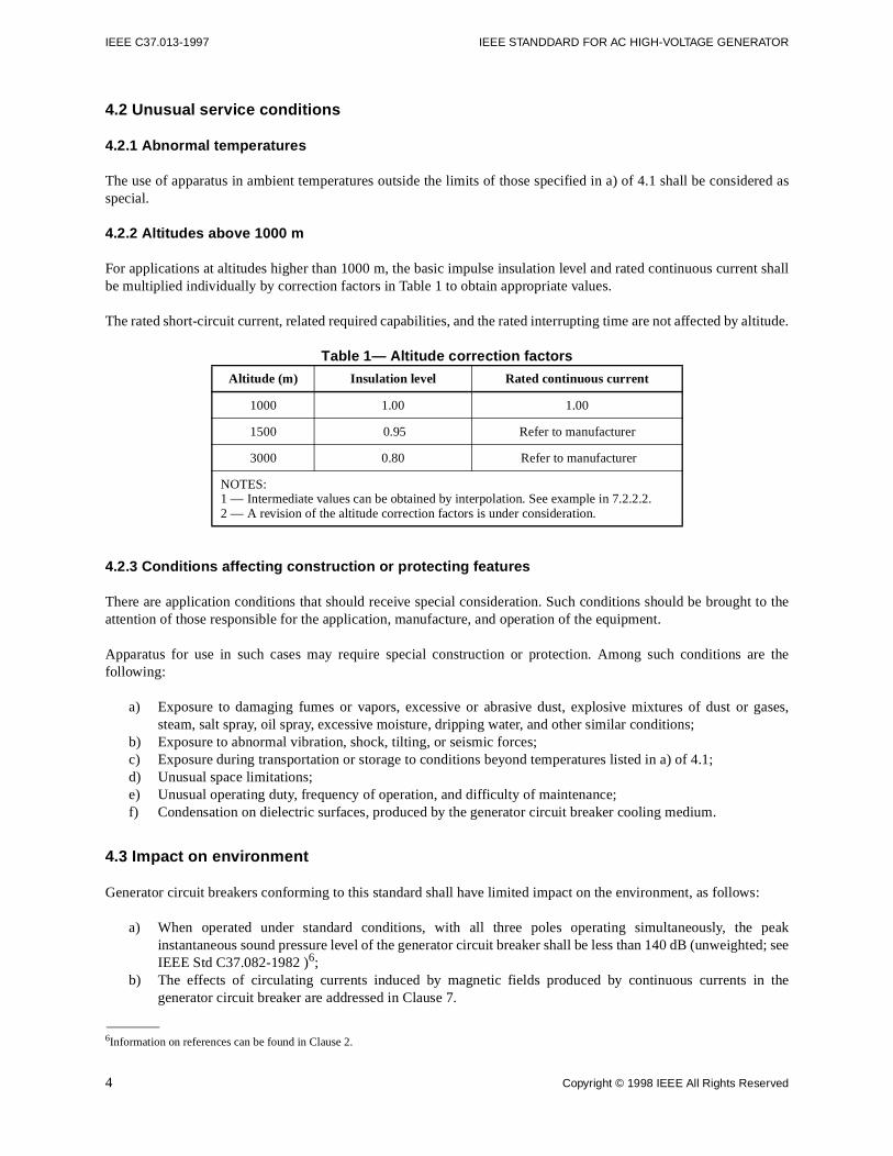
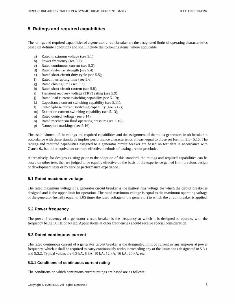
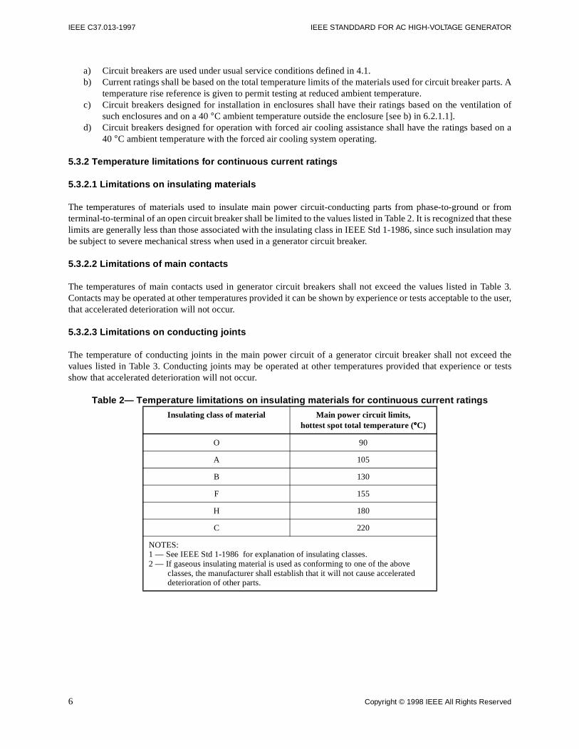

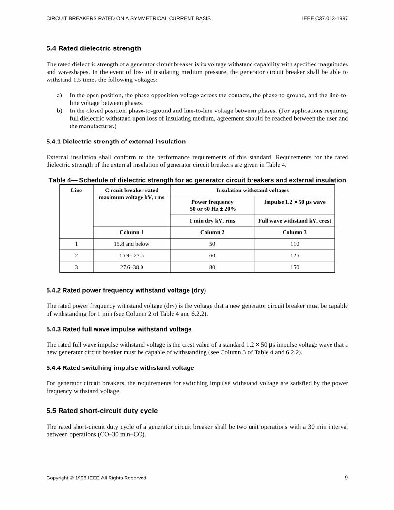
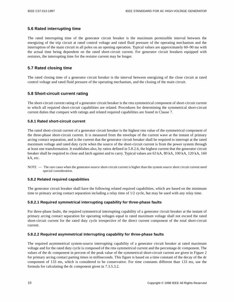
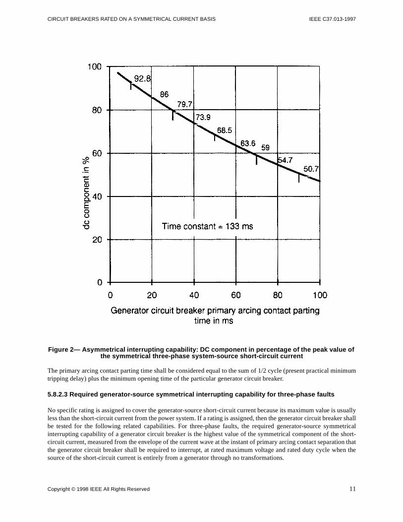
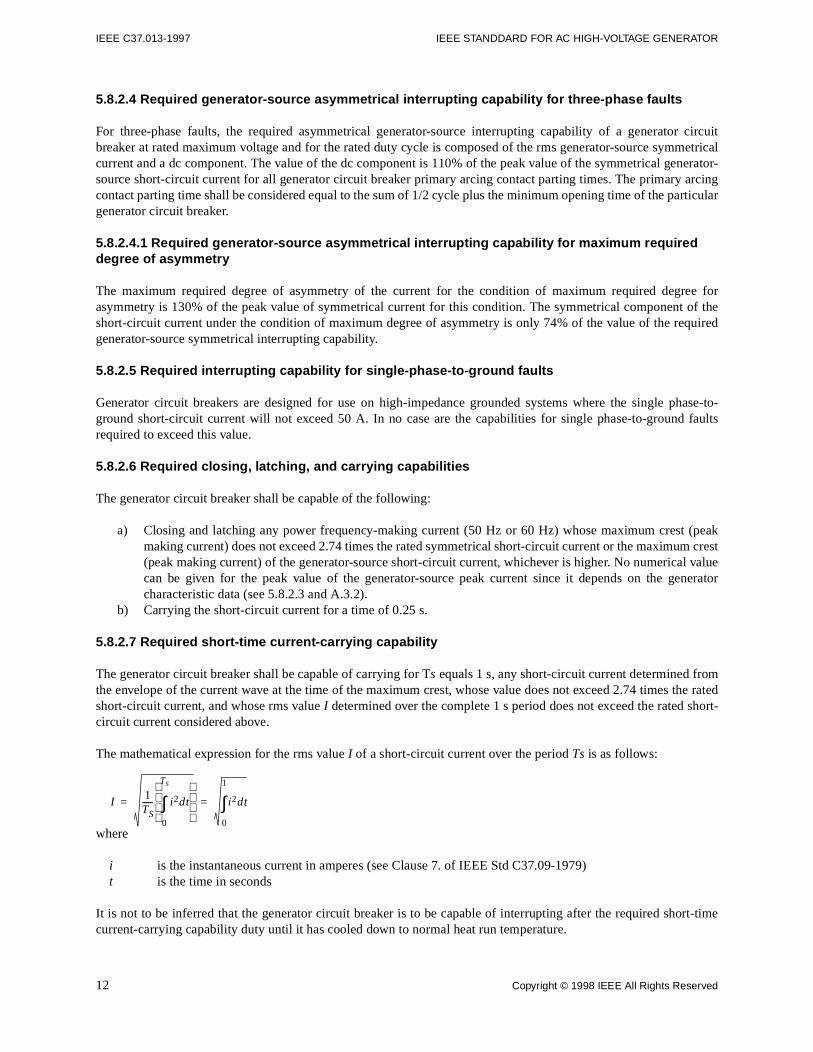
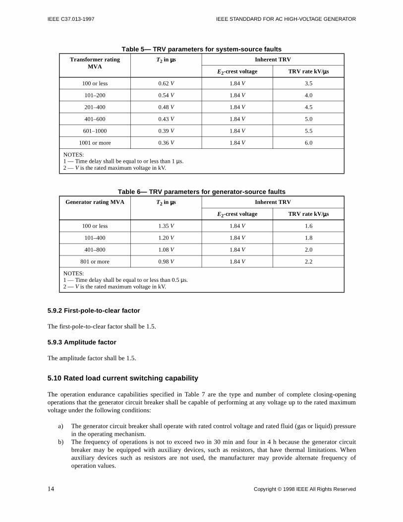

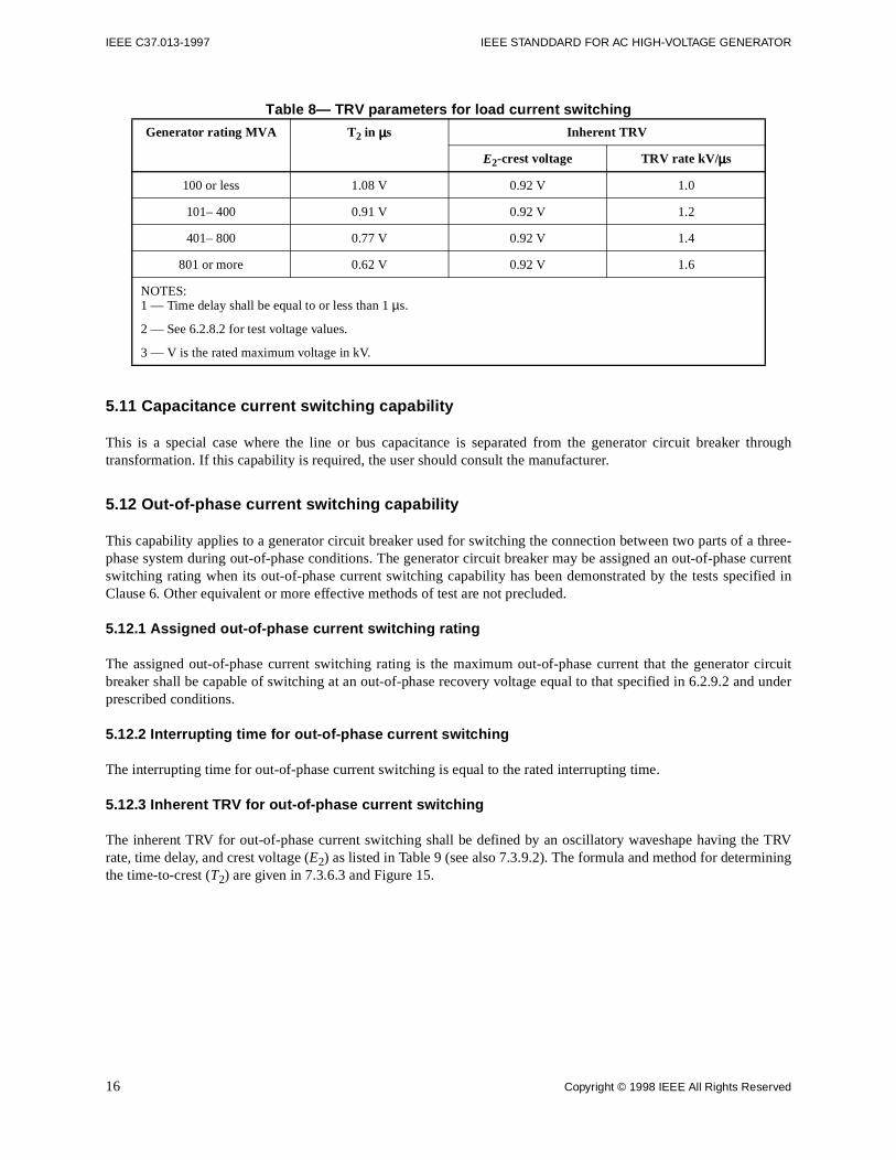
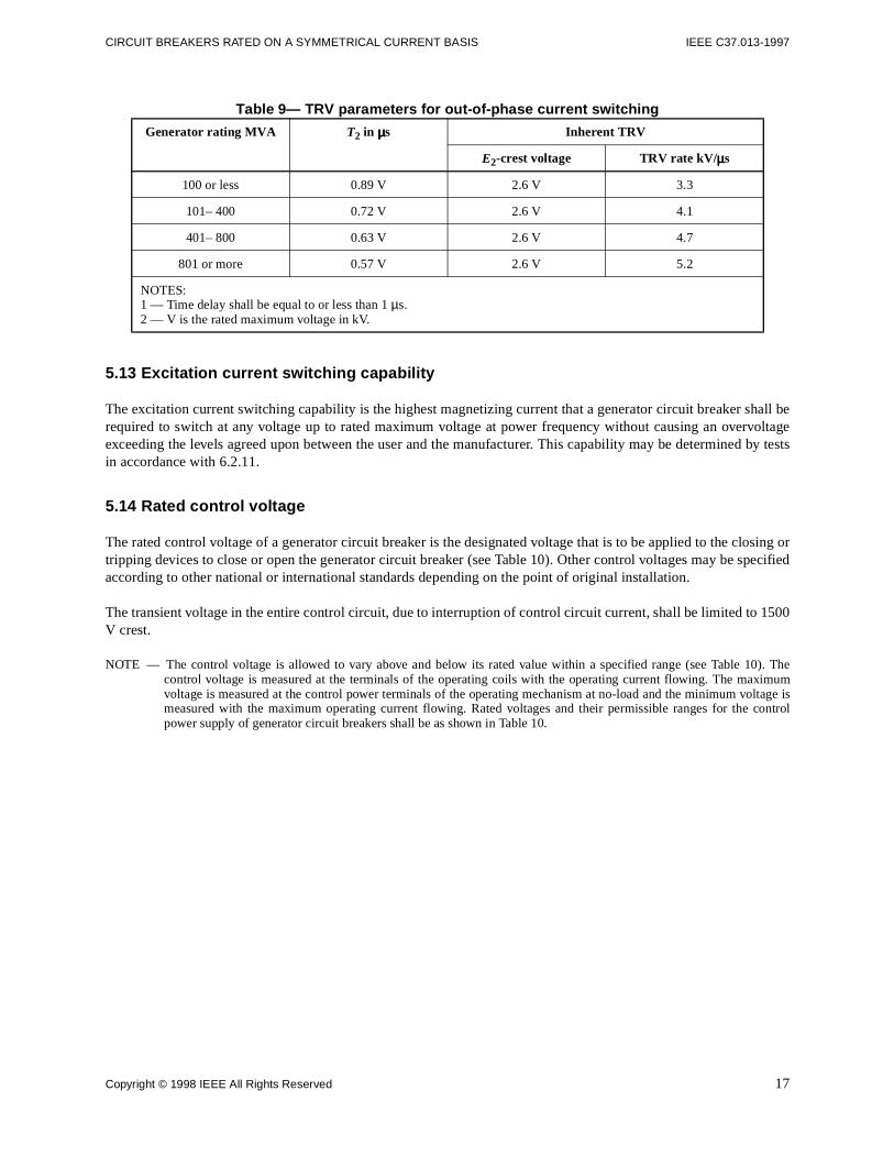
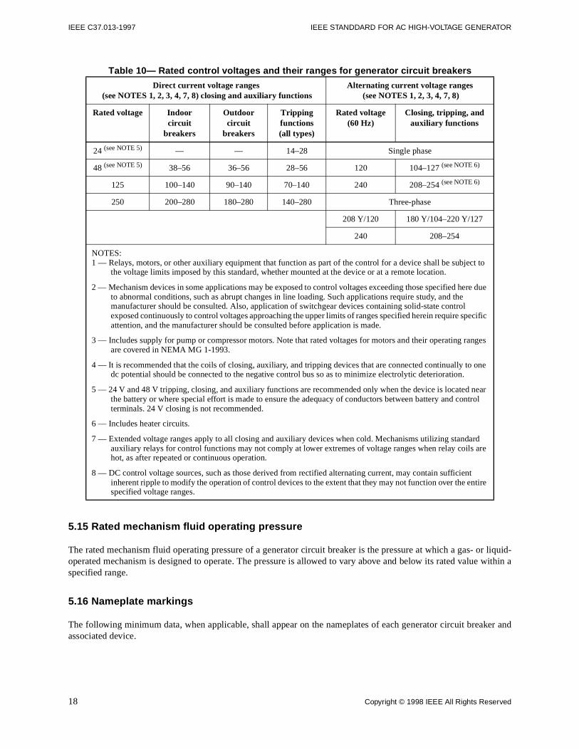
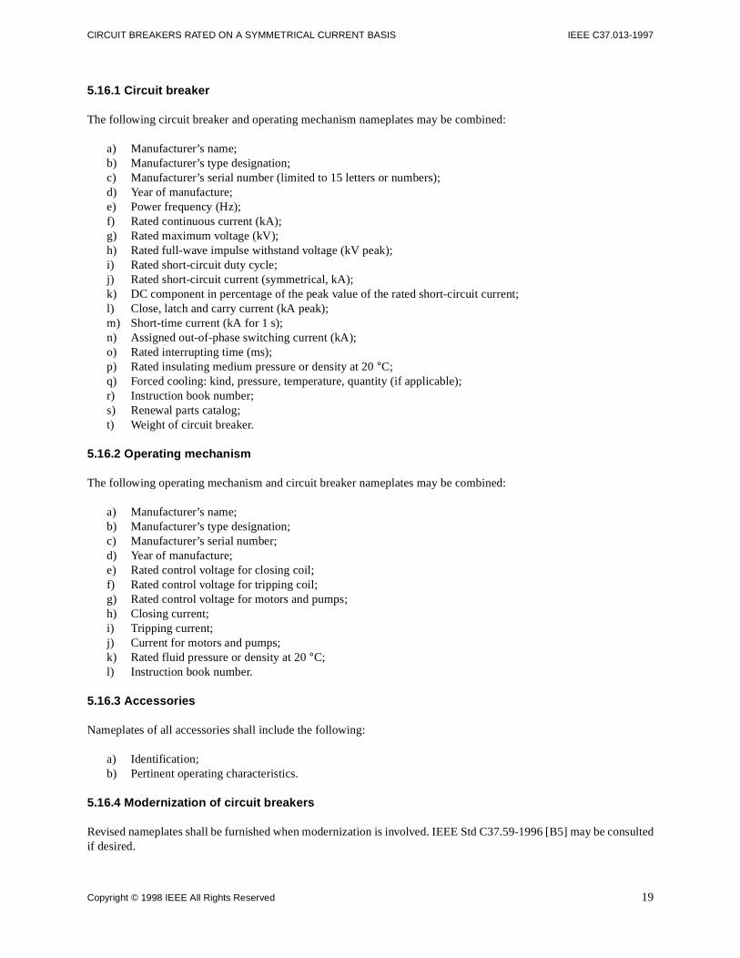
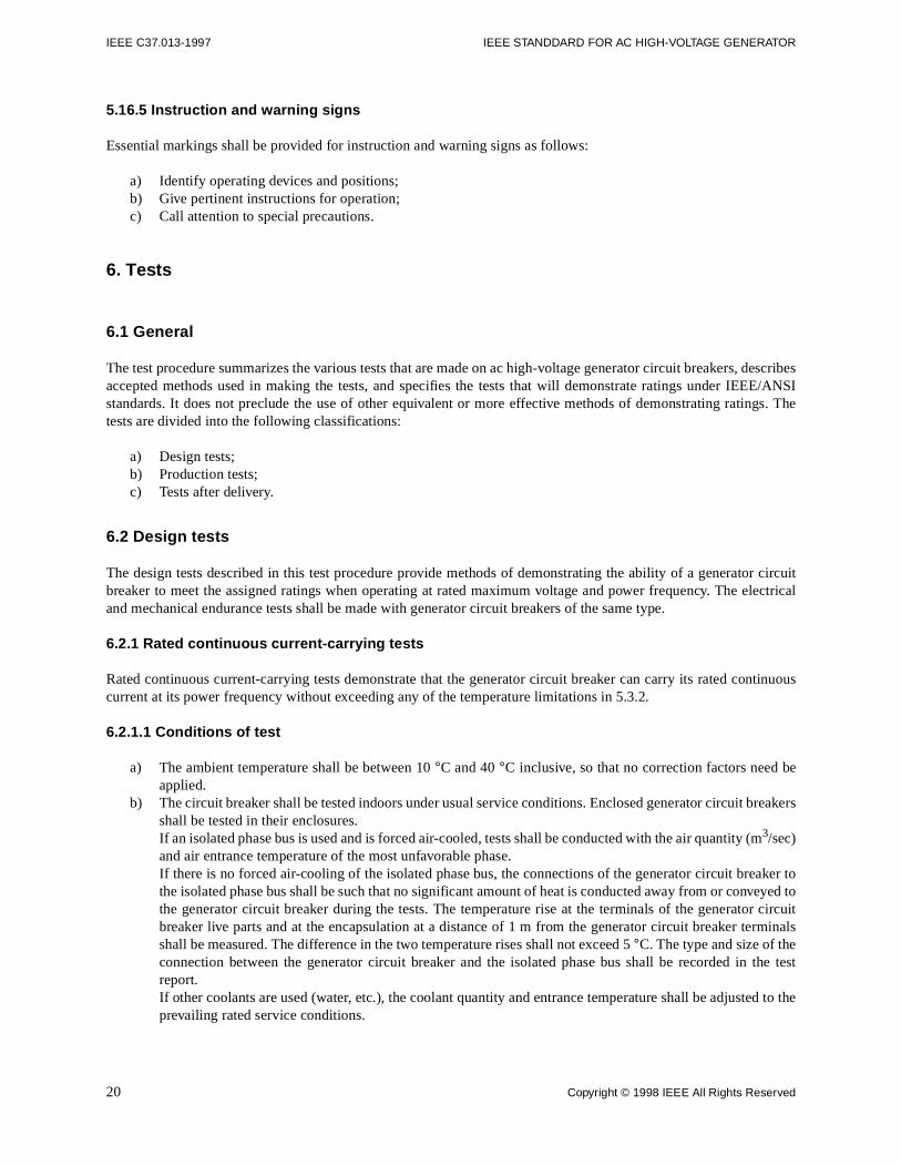
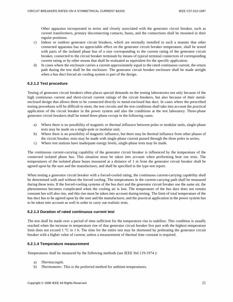

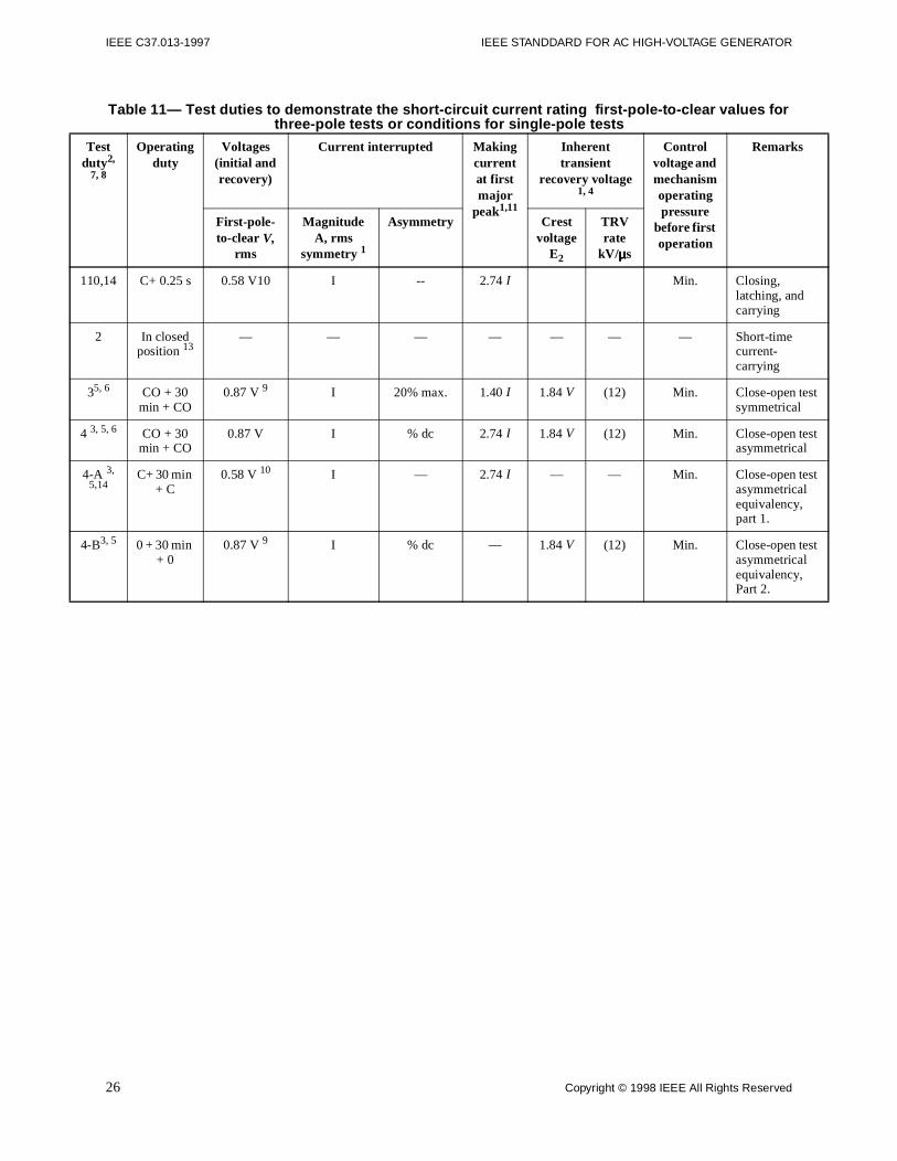
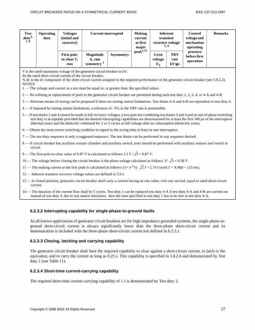

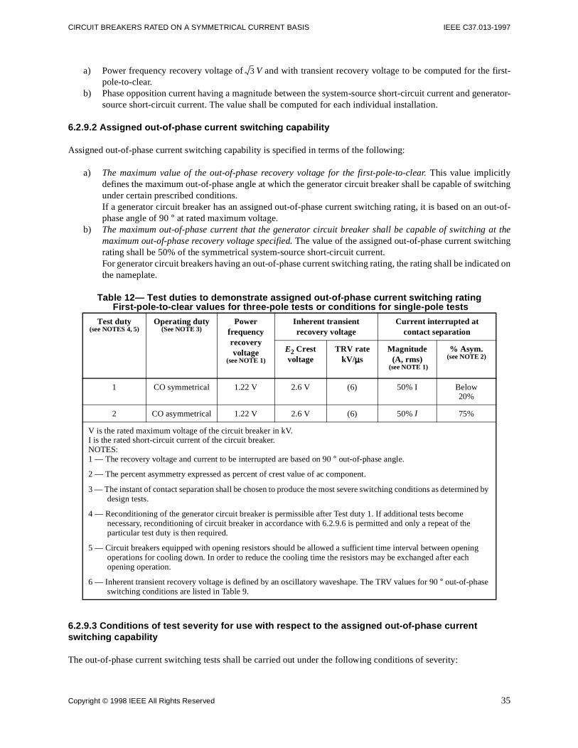

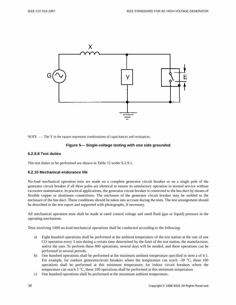
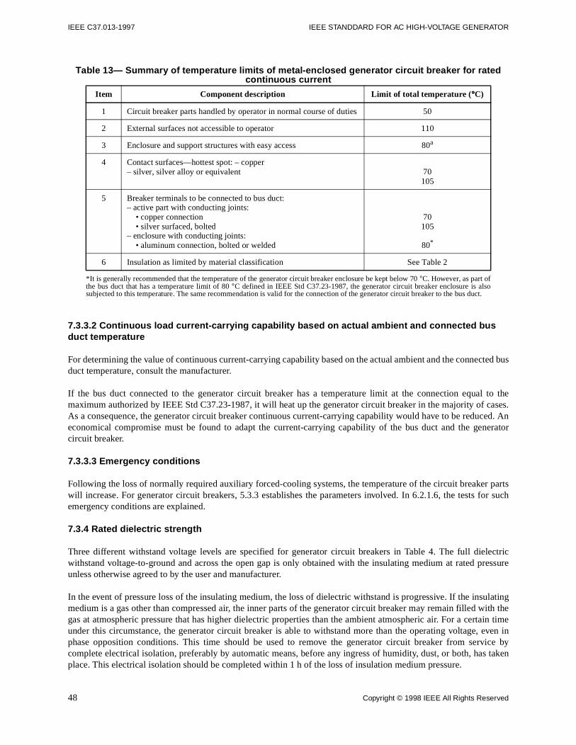
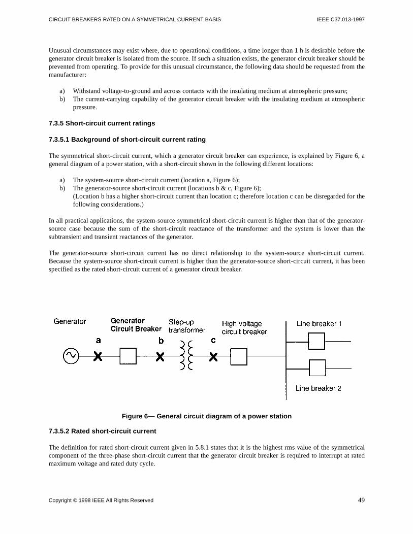
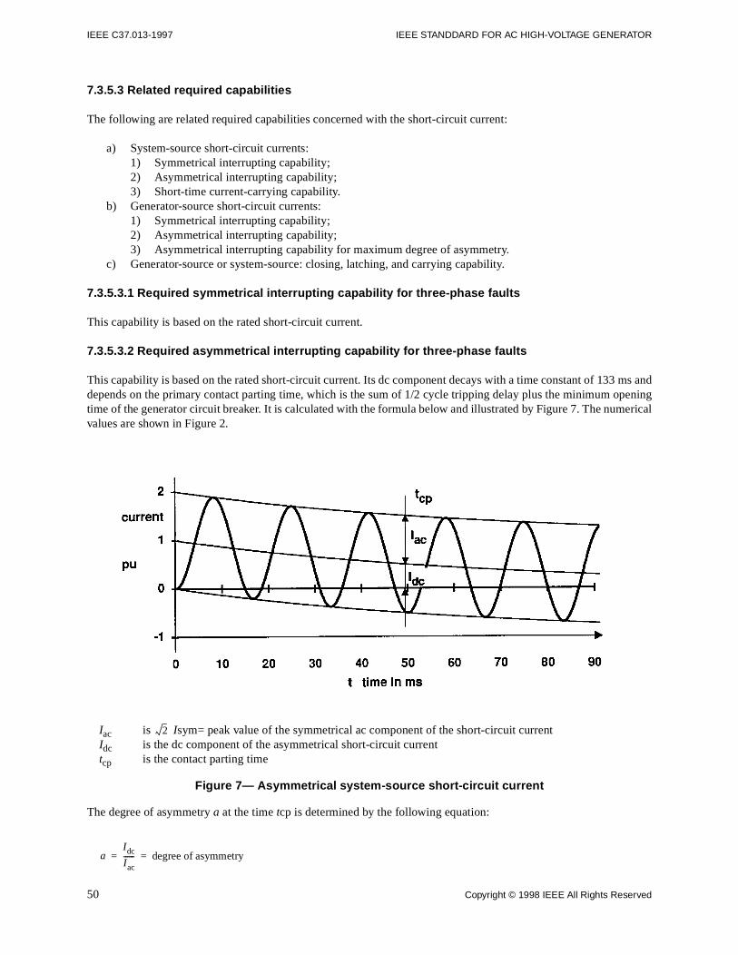
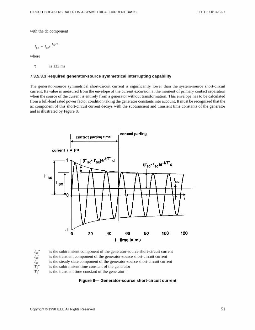
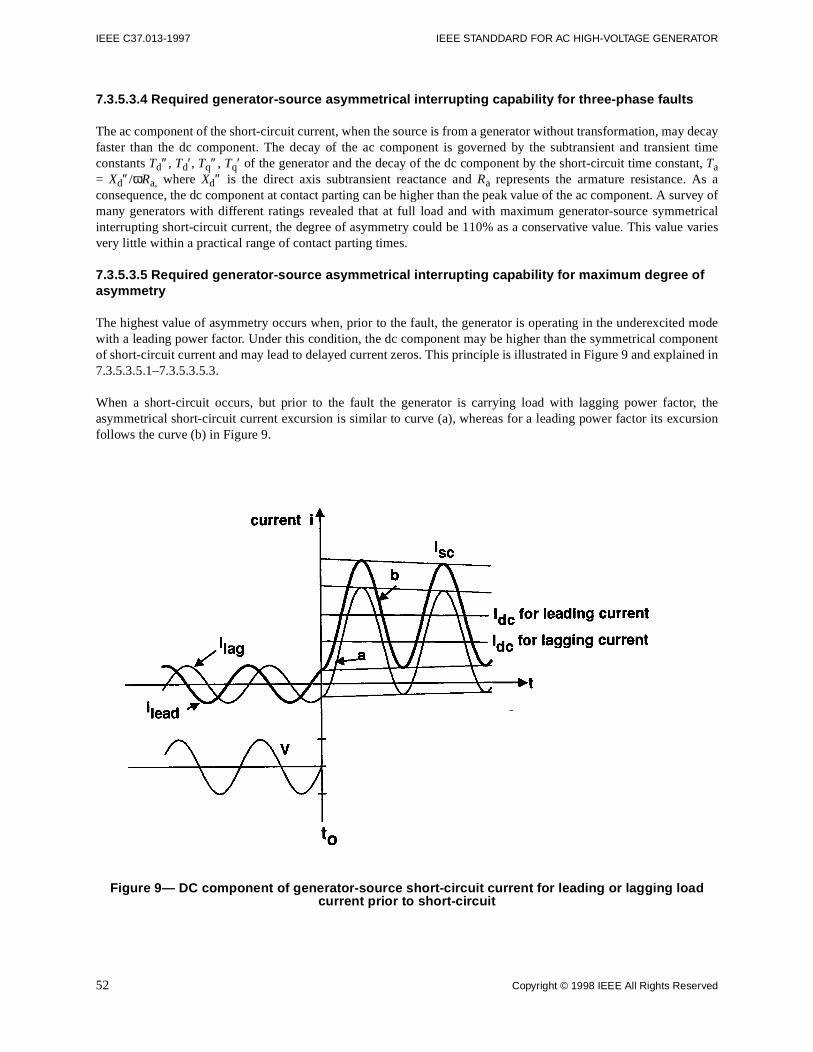
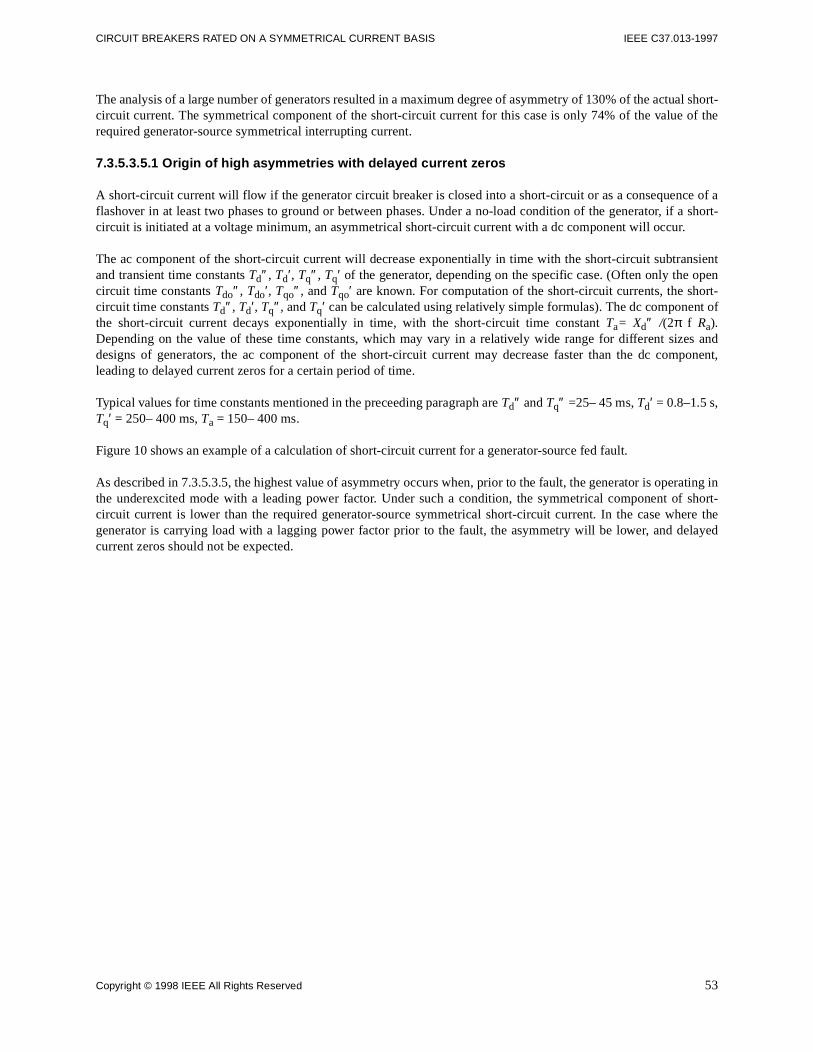
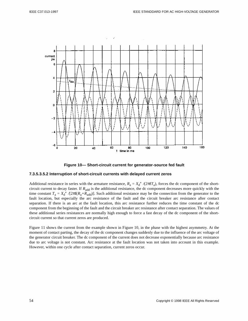
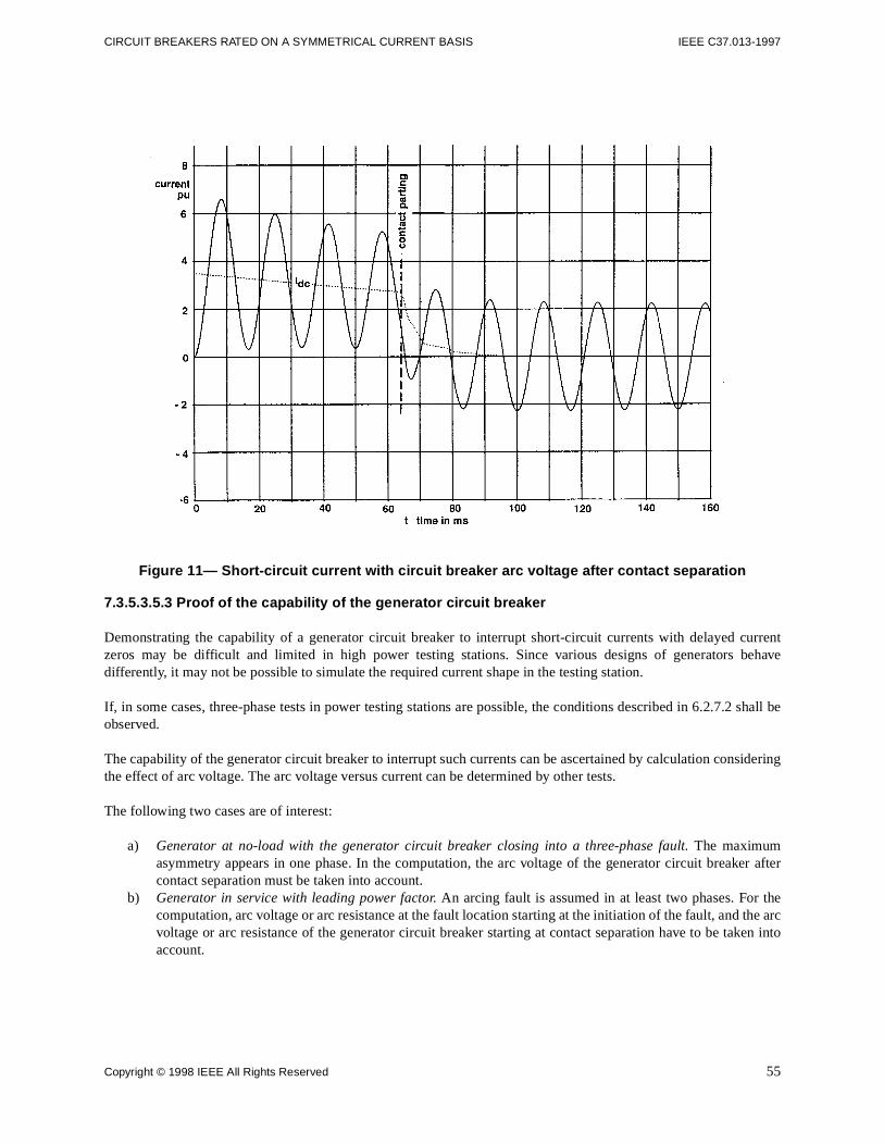
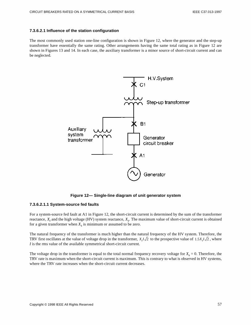
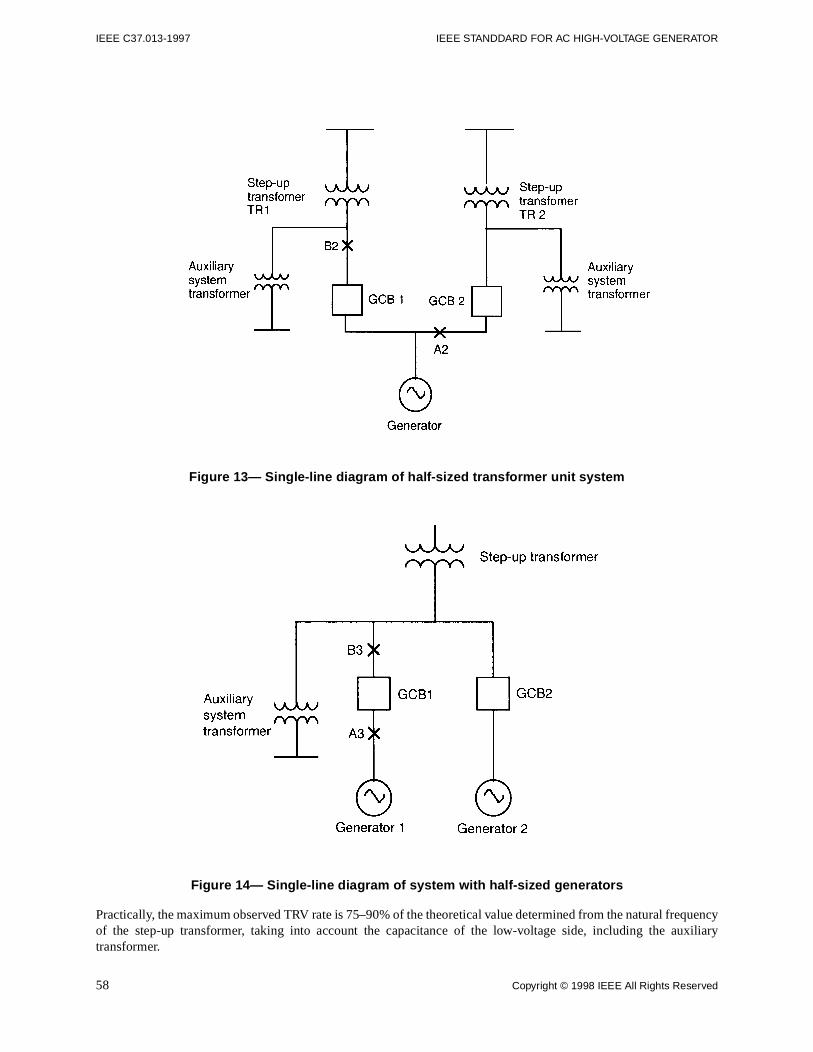
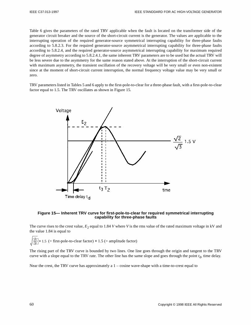
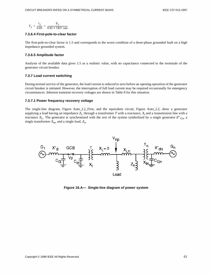
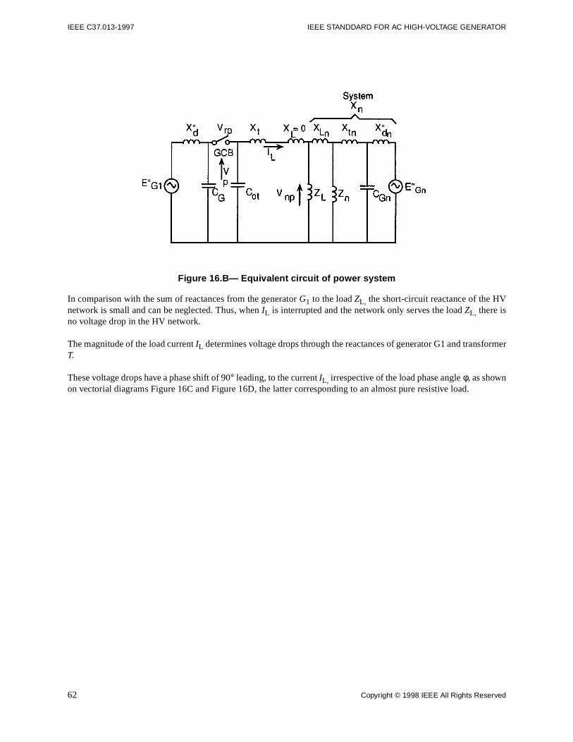


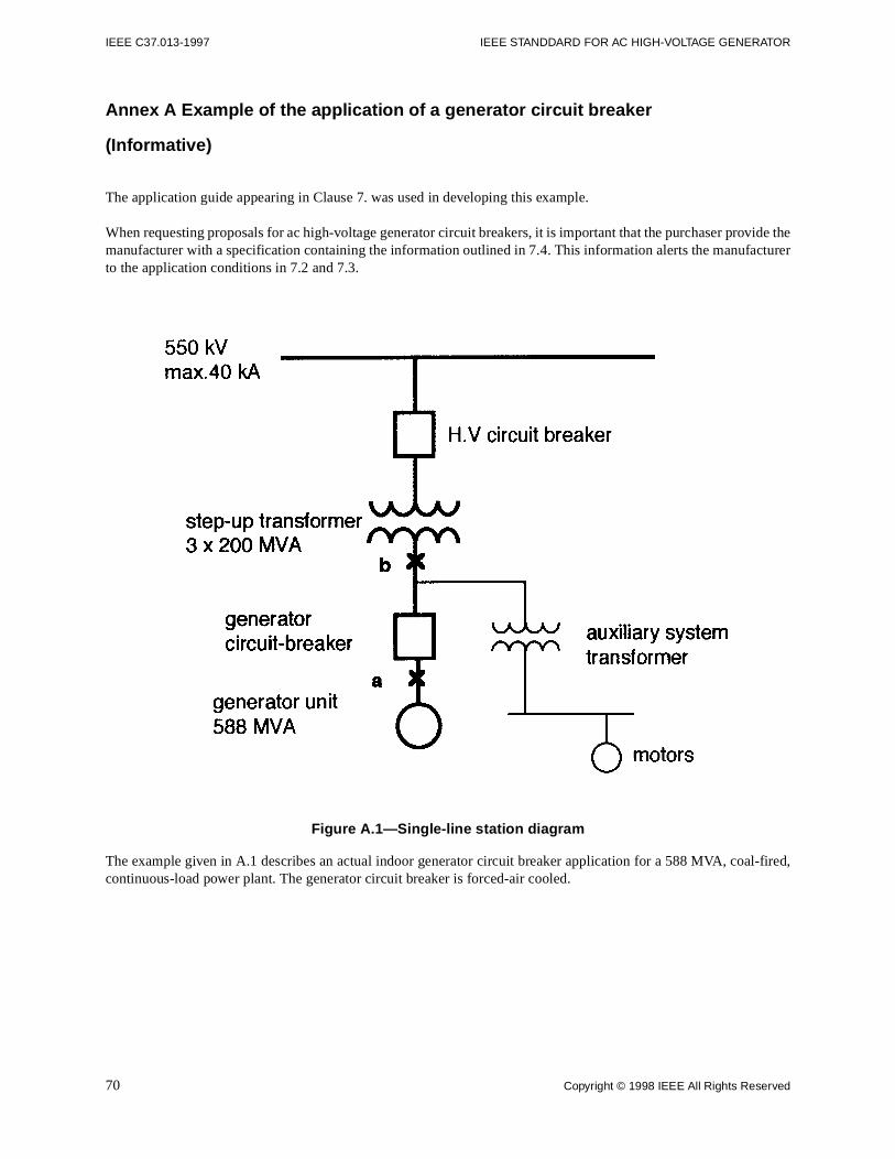

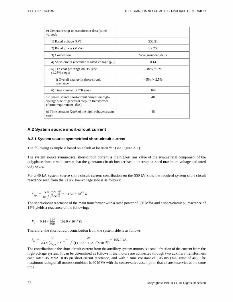
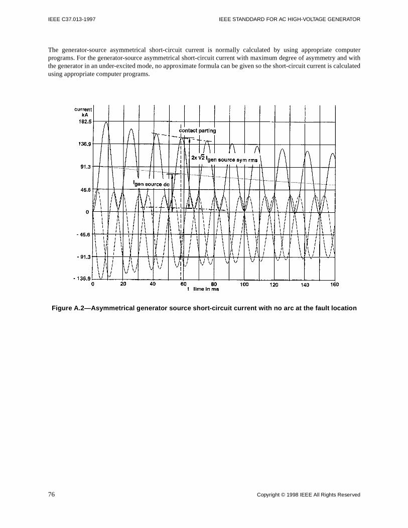
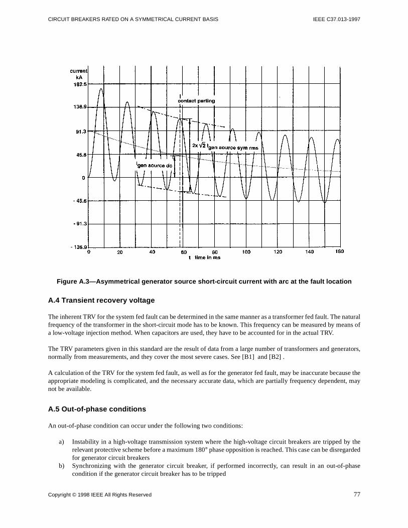
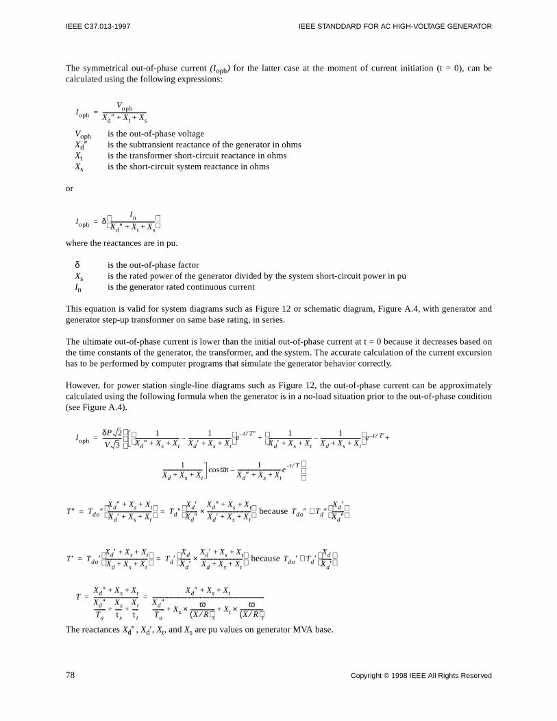
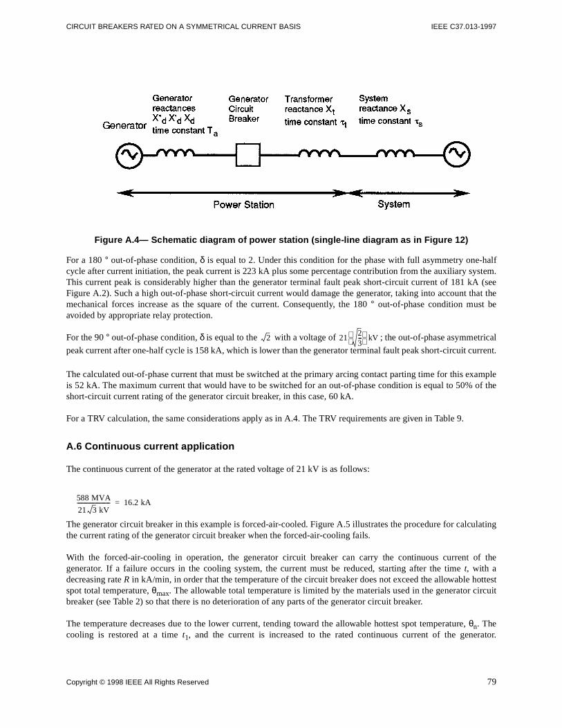
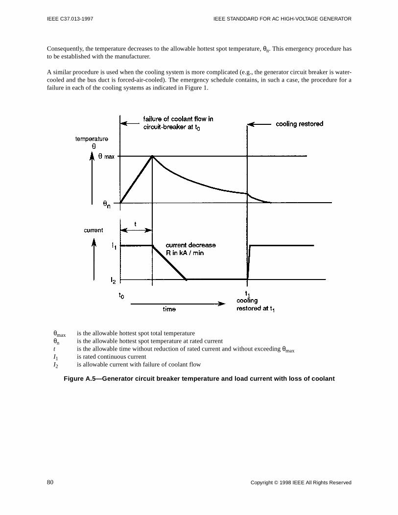


![IEEE TRANSACTIONS ON INDUSTRIAL INFORMATICS 1 ...hongwei/group/... · Earliest Deadline First (EDF). Wireless Sensor-Actuator Networks (WSANs). [37] An IEEE 802.15.4 network operating](https://static.documents.pub/doc/80x56/5f96d06e08384f3acb63463f/ieee-transactions-on-industrial-informatics-1-hongweigroup-earliest-deadline.jpg)


![[C++ Korea] Effective Modern C++ Sinchon Study Item 37-39](https://static.documents.pub/doc/80x56/55a85daa1a28abc60b8b486d/c-korea-effective-modern-c-sinchon-study-item-37-39.jpg)