IEEE ROBOTICS AND AUTOMATION LETTERS, VOL. 2, NO. 1, JANUARY 2017 305
Six-Degree-of-Freedom Localization of anUntethered Magnetic Capsule Using a Single
Rotating Magnetic DipoleKatie M. Popek, Thomas Schmid, and Jake J. Abbott
Abstract—This paper presents a method to estimate the six-degree-of-freedom pose of a magnetic capsule, with an embeddedpermanent magnet and Hall-effect sensors, using a rotating dipolefield. The method’s convergence properties as a function of thenumber of distinct rotation axes of the applied field and the num-ber of complete rotations about each axis are characterized. Acrossour tested workspace, the localization error was 4.9 ± 2.7 mm and3.3 ± 1.7 degrees (mean ± standard deviation). We experimentallydemonstrate this is sufficient for propulsion of a screw-type mag-netic capsule through a lumen using a single dipole to both propeland localize the capsule.
Index Terms—Localization, medical robots and systems.
I. INTRODUCTION
W IRELESS capsule endoscopes are a promising diag-nostic tool, providing the ability to view the entire
gastrointestinal tract with minimal patient discomfort. Theireffectiveness is currently limited due to their uncontrolled na-ture, which causes the capsule to miss regions of interest. Re-searchers have been investigating a variety of methods to ac-tively propel and localize these devices to enable views of theentire gastrointestinal tract painlessly and without anesthesia[1]. Propelling capsules with magnetic fields is clinically fea-sible [2], and utilizing magnetic fields has the benefit of beingable to propel/control [3]–[7] and localize [8]–[17] the capsuleusing the same technology.
Previous work from our lab characterized the use of a sin-gle rotating magnetic dipole positioned in space with a roboticmanipulator to propel a screw-type magnetic capsule in a lu-men from any position [6]; our experimental verification previ-ously relied on cameras to localize the capsule. In this paper,we describe a companion localization method to estimate the
Manuscript received May 9, 2016; revised July 28, 2016; accepted August 29,2016. Date of publication September 12, 2016; date of current version September26, 2016. This paper was recommended for publication by Associate Editor J.Nieto and Editor C. Stachniss upon evaluation of the reviewers comments. Thiswork was supported by the National Science Foundation under Grants 0952718and 0654414.
K. M. Popek is with the School of Computing and the Robotics Center, Uni-versity of Utah, Salt Lake City, UT 84112 USA (e-mail: [email protected]).
T. Schmid is with the Department of Electrical and Computer Engineer-ing, University of Utah, Salt Lake City, UT 84112 USA (e-mail: [email protected]).
J. J. Abbott is with the Department of Mechanical Engineering and theRobotics Center, University of Utah, Salt Lake City, UT 84112 USA (e-mail:[email protected]).
This paper has supplementary downloadable material available athttp://ieeexplore.ieee.org, provided by the author.
Color versions of one or more of the figures in this letter are available onlineat http://ieeexplore.ieee.org.
Digital Object Identifier 10.1109/LRA.2016.2608421
six-degree-of-freedom (6-DOF) pose of a magnetic capsule withno prior location information other than the bounds of its poten-tial workspace, using the same magnetic field that is propellingit. We then apply that estimate to propel a capsule in a lumen.
There are several previously published magnetic localiza-tion algorithms, but most rely on external magnetic sensors andare either not compatible with magnetic actuation [8]–[11] orcurrently have a limited workspace [16]. Methods employinginternal magnetic sensors (i.e., inside the capsule) require theaddition of an accelerometer [12], [13], provide less than 6-DOFinformation [12], [16], [17], or must manipulate the position ofthe external magnetic source during localization [15], [17]. Fre-quently, localization methods rely on complicated models of themagnetic field [13]–[15], but in certain cases, which we exploit,the external magnetic source can be modeled with the simplerpoint-dipole equation.
This paper presents a localization method that solves for the6-DOF pose of a magnetic capsule while it is either stationary orin the “step-out” regime where the field is rotating too quicklyfor the capsule to rotate synchronously with the field. Similarmethods for pose detection in rotating magnetic fields exist [14],[18], but our new method is more robust to sensor noise and datasynchronization issues because it utilizes all field-sensor data in-dependently instead of relying solely on the estimated maximumand minimum field magnitudes throughout a rotation cycle, andthe entire 6-DOF pose is solved simultaneously rather than solv-ing for position and orientation sequentially. Previous methodsonly rotated the field about a single axis, but we show that us-ing additional rotation axes improves accuracy. Our improvedlocalization method was briefly introduced in [19]. In this pa-per, we provide further experimental validation and analysis ofthe convergence properties, and we experimentally demonstratethis method’s accuracy is sufficient to propel a magnetic cap-sule by combining the localization method and our previouslypublished propulsion method [6].
The paper is organized as follows: Section II details our lo-calization method. Section III describes our experimental hard-ware. Section IV simulates the expected results based on ourmethod (II) and hardware (III). Section V provides experimen-tal verification. Finally, Section VI demonstrates propulsion ofa capsule using our localization method to provide position andheading feedback.
II. LOCALIZATION METHOD
Assume that the rotating magnetic dipole (i.e., the externalmagnet) is positioned in space by a robotic manipulator, and
306 IEEE ROBOTICS AND AUTOMATION LETTERS, VOL. 2, NO. 1, JANUARY 2017
Fig. 1. Overall system setup with the robot frame origin (or ) at the centerof the external magnetic source and the capsule frame (oc ) at the center of thecapsule’s internal permanent magnet.
the dipole is located at the center of the robot’s tool frame, or ,which is also our reference frame. The capsule’s coordinate-frame origin, oc , resides at the center of the capsule’s internalmagnet. There exists some vector pc that corresponds to the dis-placement between the two coordinate-frame origins as shownin Fig. 1. There also exists a rotation matrix, Rc , that rotates thecapsule’s coordinate-frame to align with the robot’s. By solvingfor the position vector, pc , and the rotation matrix, Rc , the cap-sule’s position and orientation relative to the external magneticsource is known.
The following assumptions were made in developing thismethod: 1) The position and orientation of the external dipolemoment, mr , are known relative to a global frame. 2) mr isrotated about an axis Ω̂ such that mT
r Ω̂ = 0 is always true(throughout this paper, we use the “hat” symbolˆ to indicatea unit vector). 3) The capsule is free to move, but the dipole-field rotation is well above the step-out frequency, such thatwe can assume no net motion, and decouple the localizationand propulsion of the capsule; existing state-estimation methodscan be used to ensure this is true [20]. 4) The field of theexternal magnet can be accurately modeled by the point-dipoleequation [21]:
b(pc) =μ0
4π||pc ||5(3pcpT
c − I||pc ||2)mr =
μ0
4π||pc ||5Bmr
(1)where μ0 is the permeability of free space, I is the identitymatrix, and B = B(pc) is a symmetric matrix. In our setup, weuse a spherical permanent magnet as the external source, whichis accurately approximated by (1); errors introduced by otherexternal-magnet geometries are quantified in [22].
Consider a set of n magnetic sensors embedded inside thecapsule, each with a constant known position offset, δi , andorientation, si , expressed in the capsule frame. The positionvector, pi , describing the position of sensor i in the robot frame,is pi = pc + Rcδi . The scalar magnetic-field projection mea-sured at each sensor is found by projecting (1) onto the measur-ing axis of the sensor, si :
bi(pi) = sTi RT
c
μ0
4π||pi ||5(3pipT
i − I||pi ||2)mr (2)
From [23], a rotation matrix can be reduced to three variablesusing its exponential form:
Rc = eS{k} (3)
Fig. 2. A diagram depicting our localization method.Bm is an array of sensormeasurements in one batch of data, M is the set of mr corresponding in timeto each set of n sensor measurements in Bm , and q is the capsule’s state, whichis iteratively updated from an initial guess.
where S{k} is a skew-symmetric matrix packing of the angle-axis representation k = k̂θ.
The capsule’s full 6-DOF pose is represented by q =[pT
c kT]T
. We use the nonlinear least-squares Levenberg-Marquardt algorithm [24] to estimate the capsule pose by min-imizing the cost function c = ||Bm − Be ||2 , where Bm is anarray of the measured magnetic field readings, and Be is an ar-ray of the magnetic field readings estimated by (2). A diagramof our method is shown in Fig. 2; the capsule’s state is iterativelymanipulated using the Levenberg-Marquardt algorithm until aminimum c is found. We use a numerically approximated Ja-cobian in our testing, both in MATLAB (calculated by defaultwhen using lsqnonlin()) and in C++ with the NonLinearOpti-mization module of the Eigen library [25].
A static magnetic field does not provide enough informationto uniquely determine the capsule’s pose; additional data must beobtained by either translating or rotating the external dipole. Thismethod can be utilized in applications with any changing appliedmagnetic field that can be modeled by (1), however, this paperdeals exclusively with a rotating dipole field to be consistent withour previous propulsion method [6]. Using a dipole field thatrotates about only one axis will result in limited information incertain configurations; for example, if the dipole is located alongthe axis of rotation of the capsule, the field’s magnitude alongthe capsule’s axis may remain constant throughout the rotationof the dipole. As detailed in [18], there also exist multiple posesin the workspace that produce the same magnetic field if thedipole is rotated about only one axis. Because we do not haveprior knowledge of the capsule’s pose, the choice of a singleΩ̂ for robust localization across the entire workspace is notfeasible. To span the workspace, we chose to populate Bm byrotating the dipole source about its three coordinate-frame axes(xr ,yr , zr ) successively for a single dataset. The number ofdistinct Ω̂ and the amount of data needed for the algorithm toconverge is explored in Section V.
III. EXPERIMENTAL HARDWARE
A. Magnetic Dipole Source
The experimental setup is shown in Fig. 3(a). The spherical-actuator-magnet manipulator (SAMM) [26] is used as the ex-ternal dipole. The device provides a singularity-free method forcontrolling a spherical permanent magnet’s dipole orientation
POPEK et al.: SIX-DEGREE-OF-FREEDOM LOCALIZATION OF AN UNTETHERED MAGNETIC CAPSULE 307
Fig. 3. (a) The experimental setup with the SAMM mounted on the end-effector of a 6-DOF robotic arm, the stereo vision system used for ground truth,and our capsule constrained to a lumen where it is free to rotate about its longaxis, but not translate. (b) The test fixture used to rigidly mount the sensor array.(c) Experimentally tested positions of the dipole are denoted by red dots andtheir corresponding direction vectors in the capsule’s frame. The distance to thecapsule was varied.
by using three mutually orthogonal omniwheels to generaterotation about arbitrary axes. The SAMM is mounted as theend-effector on a Yaskawa Motoman MH5 6-DOF robotic ma-nipulator. We chose our workspace to span between 75–200 mmfrom the center of the permanent magnet to ensure a high signal-to-noise ratio. Its size is limited by a combination of the strengthof the prototype SAMM’s permanent magnet and the sensitivityof the Hall-effect sensors. Due the homothetic property of mag-netic fields, if the SAMM’s magnet radius were scaled by η thefield measured at ηp would be the same as that measured at pwith the original magnet. Tested locations were normalized bythe radius ρ of the SAMM magnet, which is 25.4 mm, to enableour results to generalize to other magnetic field sources. Theeffect of increasing the sensor’s sensitivity is not as straight-forward because of the exponential decrease in magnetic fieldmagnitude with distance, but typically more sensitive sensorshave a smaller range and thus less measurement noise. Whenusing higher sensitivities, one should ensure the sensing rangeis large enough to accommodate the desired range of externalfield measurements when combined with offsets from the inter-nal magnetic field.
To quantify the accuracy of the proposed localization method,the capsule was mounted with accuracy of 1.5 mm and 3◦ us-ing the test fixture shown in Fig. 3(b). The SAMM was movedrelative to the fixed position of the capsule along seven direc-tions spread throughout an octant of the workspace as shown inFig. 3(c). The distance ||pc || was varied between 4ρ to 8ρ. Ateach location, the SAMM’s position was held constant and mr
was rotated about seven different rotation axes, for five completerotations each, to characterize the convergence properties of thelocalization method. Ten trials were completed at each loca-tion for statistical analysis. To ensure the tests with a stationarycapsule give comparable results to more clinically realistic sce-narios, the capsule was also tested in a lightly lubricated clearacrylic tube where it was free to rotate (Fig. 3(a)). The SAMM’s
Fig. 4. (a) A magnetic dipole field has regions where the field vector pointsin a single cardinal direction, denoted by dashed/dotted lines. Place bz sensorsalong the red dashed lines and by sensors in regions denoted by the black dottedlines (with bx sensors placed analogously). (b) An isometric view of our finalsensor layout with each sensor labeled with its measured field direction, and itsposition offset in mm with respect to the center of the magnet. The gray sensorsare not visible from this angle, but are located at the negative counterpart of thecorresponding sensor. (c) The sensor array (i.e., the hardware implementationof (b)) surrounding a permanent magnet. (d) The communications electronics.(e) Our capsule compared to Given Imaging’s colon capsule. Along with theelectronics shown in (c) and (d) it contains coin cell batteries on each end.The wires connnecting the batteries to the electronics run along the inside of thecapsule and are not visible.
maximum rotation speed is 3 Hz; to ensure the capsule remainedin the step-out regime, these tests were performed at ||pc || = 7ρ.Closer distances could be achievable using an electromagneticdipole source such as an Omnimagnet [27] and localizing withrotation speeds of 20–30 Hz, or by constructing a faster SAMM.
B. Prototype Capsule
This method was designed to be used in conjunction with amagnetic capsule with Hall-effect sensors embedded. One ofthe major problems associated with internal magnetic sensors,if used in conjunction with magnetic propulsion, is their closeproximity to the capsule’s internal magnet, whose field maydominate the external field we are trying to sense. One op-tion is to employ large-range sensors, but these typically havemore noise associated with their measurements at the signalsof interest. An alternative, which we first presented in [20], isto strategically surround the internal magnet with six one-axissensors that have negligible biasing in the sensor measurementsfrom the internal magnet’s field. Assuming the capsule’s internalmagnet can be modeled using (1), there are positions where themagnetic field points in a single cardinal direction as illustratedby the dashed/dotted lines in Fig. 4(a). By using a one-axis Hall-effect sensor, which measures the field component orthogonalto its surface and ignores all other field components, it is pos-sible to place the sensor such that the internal magnet’s field isparallel to the sensor’s surface and provides negligible interfer-ence in its measurements. For example, the sensors measuringthe field component in the zc direction are placed at locations
308 IEEE ROBOTICS AND AUTOMATION LETTERS, VOL. 2, NO. 1, JANUARY 2017
where the field vector lies solely in the xc − yc plane. Thesepositions, denoted by dashed red lines in Fig. 4(a), lie along aline drawn out from the middle of the magnet at an angle ofapproximately 55◦ measured from mc . The bx and by sensorsare placed in regions parallel and perpendicular to mc , denotedby black dotted lines in Fig. 4(a). Using this strategy, we placedsix sensors, one on each side of a cube, to provide two sensorsin each of the three cardinal axes. As a cubic magnet is notperfectly modeled by (1) in the region where the sensors areplaced, our final sensor positions were confirmed using finite-element-analysis software. The final sensor layout is illustratedin Fig. 4(b) and was chosen to be as close as possible to the idealwhile still being feasible within our hardware constraints.
The sensor array was created using six printed circuit boards(Fig. 4(c)); on each was placed a one-axis Allegro A1392 linearHall-effect sensor with a range of ±62 mT and a sensitivityof 25 V/T. The boards were mounted directly to the 108 mm3
cubic NdFeB Grade N52 magnet in the layout shown in Fig. 4(b).Using our sensor configuration, the maximum offset from theinternal magnet is 8.2 mT, which is measured by a by sensor.The average field offset across all six sensors is 2.9 mT. This isa significant improvement over the naive alternative of placingthe bz sensor along the zc -axis at 4.0 mm, similar to the bx andby sensors; the field from the capsule’s magnet at this positionwas measured by a Hirst GM08 gaussmeter as approximately300 mT, which would saturate the sensor and make it useless.The small constant biases can be subtracted in software becausethe sensors remain fixed relative to the internal magnet.
The four-layer circular board (Fig. 4(d)) contains all the com-ponents to wirelessly transmit the six sensor readings to a com-puter. A Texas Instruments CC2530 microcontroller (MCU)was chosen for its low-power consumption and its internaltransceiver. The MCU uses an interrupt-based approach to tran-sition between the capsule’s states and execute functions thatrequire constant timing intervals. During a test, the sensors areread every 10 ms, but are sent wirelessly in batches of fivereadings per sensor at 20 Hz back to the computer. Before trans-mission, the measurements are timestamped on the MCU. TheMCU and PC clocks are synchronized to ensure each mr is cor-rectly attributed to its corresponding sensor measurements bysending a flag to the MCU to start its timers at a known PC time.Two 1.55 V silver-oxide Energizer 386/301 watch batteries wereused to power the capsule, which typically last one hour. Thebatteries and electronics were incorporated into a 3D-printedcapsule as shown in Fig. 4(e).
The capsule used here (Fig. 4(e)) is a scaled down versionof the one first presented in [20]. It is approximately 1.4 timesthe length of commercial capsule endoscopes and 1.2 timesthe width, with a length of 42 mm and diameter of 13.5 mm,not including a 1 mm helical thread used for propulsion. Forcomparison, Fig. 4(e) shows our capsule with Given Imaging’scolon capsule along with a U.S. quarter. The size is constrainedby the batteries. With these components a 1.2-scaled capsulewas originally designed, but our batteries’ steel casings be-came magnetized in the rotating field and created an unmod-eled disturbance resulting in poor pose estimation. As a result,we lengthened our capsule slightly to mitigate this problem.In the future, custom non-magnetic batteries could be utilized;
Fig. 5. Assuming the origin is located at the center of the external magneticsource, the workspace is restricted to a hemisphere in the negative zr direction.Poses were randomly generated across the workspace, depicted by dots. Thefive initial states corresponding to the bottom rows of Table II are depicted inplanes (a) and (b).
commercial low-magnetic batteries do not meet both our sizeand power constraints [28].
C. Sensor Calibration
Assuming the magnitude of the SAMM’s dipole and eachsensor’s position offset is known, the sensitivities and orienta-tions of the sensors were estimated using a constrained nonlinearleast-squares algorithm to ensure accurate measurements. Thesensor array was placed in the rigid test fixture (Fig. 3(b)) andthe SAMM was moved relative to the capsule in a grid pattern(60 (w) × 60 (d) × 20 (h) mm3) in 10 mm step increments,with the center of the grid 110 mm above the capsule; mr wasfixed throughout the test. A single dataset combined from twotrials with dipole orientations of [0 0 1]T and [0 0.707 0.707]T
was used. The sensitivity and orientation of each of the six sen-sors was solved simultaneously by estimating the readings using(2) and comparing them to the sensor measurements using thecost function e = ||Vm − Ve ||2 . The comparisons were done interms of the voltage output of the sensor because the sensitivityconstant (α) that converts volts to mT was unknown. Vm is anarray of voltage readings from the six sensors, and Ve = Beα.A total of 24 parameters were estimated: the fixed 6-DOF poseof the capsule, and three parameters for each of the sensors (the2-DOF pointing orientation s, and the scalar sensitivity α).
To evaluate the results of our sensor calibration, we comparedthe localization results using both the original nominal sensorvalues and the calibrated values across 210 tests with ||pc ||spread evenly between 4ρ, 6ρ, and 7ρ. The nominal values(before calibration) resulted in a mean error of 4.9 mm and 7.8◦,and a maximum error of 10.0 mm and 12.6◦. The mean errorusing the calibrated values was reduced to 4.1 mm and 3.0◦ withthe maximum error reduced to 8.6 mm and 6.2◦.
IV. CHARACTERIZATION USING SIMULATIONS
Initial testing of the localization method was performed witha MATLAB simulation based on our experimental hardware,as depicted in Fig. 5. The origin of the SAMM’s magnet wascentered on the top surface of the workspace, whose plane liesorthogonal to the zr axis. A spherical workspace was chosen to
POPEK et al.: SIX-DEGREE-OF-FREEDOM LOCALIZATION OF AN UNTETHERED MAGNETIC CAPSULE 309
TABLE ICOMPONENTS WHERE NOISE AND UNCERTAINTY WERE ADDED TO IMITATE
EXPERIMENTALLY MEASURED RESULTS
Source of error range
Sensor noise ±0.114 mTTime difference between sensor and dipole readings ±2 msCapsule position uncertainty 1.5 mmCapsule orientation uncertainty 3◦
Dipole position uncertainty 0.5 mmDipole orientation uncertainty 2.4◦
Dipole magnitude uncertainty ±5%
test positions uniformly; it can be reduced to a hemisphere inour application of capsule endoscopy because the capsule willreside in the human body, whose local tangent plane can bedrawn to cut the spherical workspace in half. Due to hardwareconstraints, the capsule cannot be closer than 3ρ to the center ofthe SAMM’s magnet, so the hemisphere shape is further reducedto a spherical shell that spans from 3ρ to 8ρ as shown in Fig. 5.Each of the tested 6-DOF poses were randomly generated fromthe workspace.
In ideal conditions, if no noise or uncertainty is modeled,the algorithm estimates the capsule’s pose with only roundingerror in both the position (4.6 × 10⁻¹⁴ mm) and orientation(3.4 × 10⁻¹⁴ ◦), across 100 random poses. However, the sen-sor array and the dipole field have uncertainties, and signalsare noisy, so a more realistic simulation was conducted wherenoise and uncertainties were added. These sources, which werederived from our experimental hardware, are listed along withtheir ranges in Table I. Note the sensor noise remains constant,so as ||pc || increases, the magnitude of the external field and thesignal-to-noise ratio decrease, resulting in worse localization.The position and orientation uncertainty, both for the capsuleand dipole source, stem from how accurately our ground truthis known. The time difference is a result of our time resolution.Including the noise and uncertainty resulted in an error of 2.2±0.8 mm and 1.7◦ ± 0.9◦ across 100 random poses (through-out this paper all errors are reported as the mean ± standarddeviation). The orientation error is in terms of the angle-axisrepresentation.
A known limitation of iterative methods is their dependenceon the initial condition; if it is not in close proximity to theglobal minimum (the true capsule pose) the method may con-verge to a local minimum and result in poor localization. We donot assume prior knowledge of the capsule’s pose, so the initialguess was chosen directly below the SAMM centered verticallyin the hemispherical workspace with an orientation matchingthe external magnetic source’s frame. Across 1,000 randomposes, 98.7% resulted in a average error of 2.3 ± 1.0 mm and1.8◦ ± 0.8◦. The remaining 1.3% converged to an incorrect localminimum, typically, a pose that mirrors the true capsule pose.To ensure safety, we desire an algorithm that always convergesto the global minimum.
One option to overcome the problem of local minimums isusing an additional algorithm to estimate an initial conditionthat will be in close proximity to the optimal pose [10], and ourprevious non-iterative algorithm could be used to provide aninitial guess [18]. Another option is to choose multiple initial
TABLE IIPERCENT CONVERGENCE TO TRUE CAPSULE POSE USING VARIOUS INITIAL
STATES WITH POSITION VECTOR pc IN MM AND ORIENTATION
ANGLE-AXIS k IN RAD
Initial Initial Tested ConvergenceState pc State k poses
conditions spread throughout the workspace and select the onethat results in the minimum norm in the residual error betweenthe sensor measurements and their estimates. Because we havea known workspace, if the algorithm converges to a positionoutside of the workspace (e.g., pc has a positive z component)it is not considered a failure; instead, the initial conditions aremodified by adding randomly generated noise from a uniformdistribution on the interval ±70 mm to each position compo-nent and a rotation on the interval of ±45◦ about a random axisand the algorithm is run again. If the algorithm converges toa position inside the workspace that is not within 10 mm ofthe true capsule pose, it is considered a failure. We found usingfive structured initial conditions was sufficient for 100% conver-gence across 10,000 random poses. The five initial conditionsare split across two planes in the hemispherical workspace asshown in Fig. 5. Other tested initial configurations along withtheir convergence rate to the true capsule pose are shown inTable II. Converging outside of the workspace is extremelyrare, it occurs less than 0.5% of the time, when using five initialconditions. If a larger workspace is used, additional initial statesmay be necessary.
If there is prior knowledge of the capsule’s pose, using a sin-gle initial condition that is within 5 cm and 90◦ was sufficientto converge to the capsule’s true pose every time over 10,000randomly chosen poses. When used for capsule endoscopy, theinitial localization will have no prior information about the cap-sule, but for subsequent tracking, the position of the capsule willgenerally be in close proximity to the previous position. How-ever, prior knowledge of the capsule’s orientation will be muchless certain, particularly considering the use of rotating fields.By reducing the bounds on the position to 3 cm, the orientationconstraints could be relaxed to 180◦ and still converge to the truepose in 99.9% of cases across 10,000 randomly chosen poses.
V. EXPERIMENTAL RESULTS AND DISCUSSION
When localizing the capsule, there is a trade-off between ac-curacy and the time to collect the sensor data. Fig. 6 compares
310 IEEE ROBOTICS AND AUTOMATION LETTERS, VOL. 2, NO. 1, JANUARY 2017
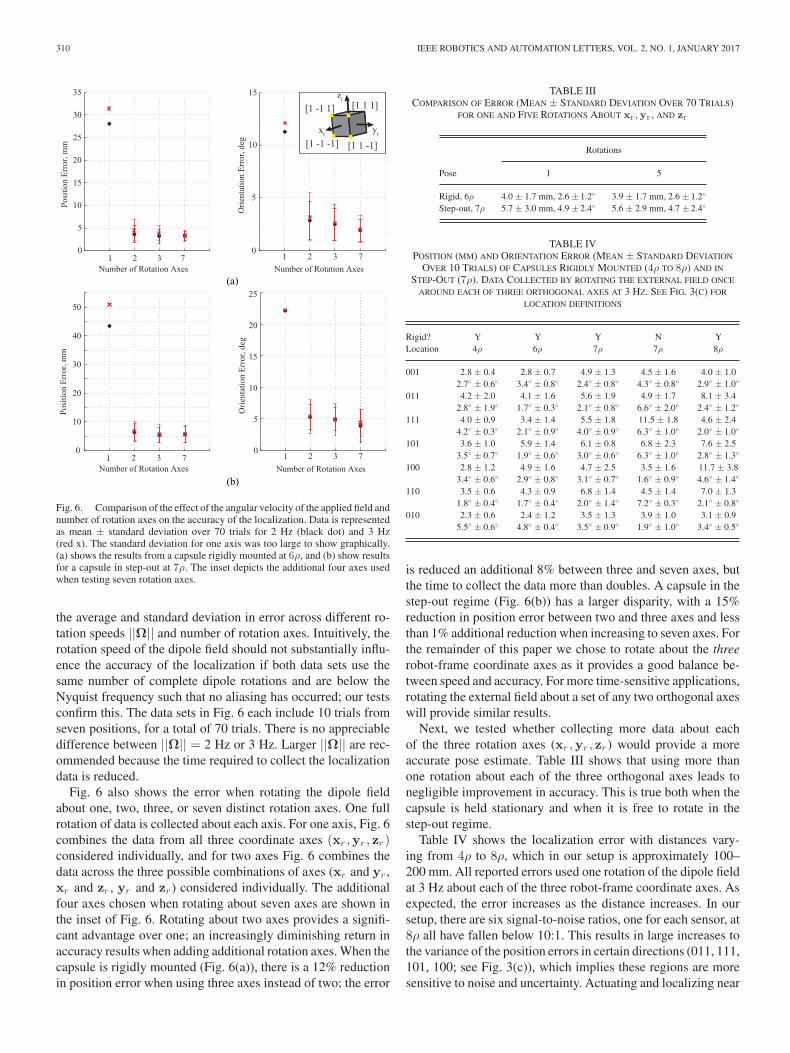
Fig. 6. Comparison of the effect of the angular velocity of the applied field andnumber of rotation axes on the accuracy of the localization. Data is representedas mean ± standard deviation over 70 trials for 2 Hz (black dot) and 3 Hz(red x). The standard deviation for one axis was too large to show graphically.(a) shows the results from a capsule rigidly mounted at 6ρ, and (b) show resultsfor a capsule in step-out at 7ρ. The inset depicts the additional four axes usedwhen testing seven rotation axes.
the average and standard deviation in error across different ro-tation speeds ||Ω|| and number of rotation axes. Intuitively, therotation speed of the dipole field should not substantially influ-ence the accuracy of the localization if both data sets use thesame number of complete dipole rotations and are below theNyquist frequency such that no aliasing has occurred; our testsconfirm this. The data sets in Fig. 6 each include 10 trials fromseven positions, for a total of 70 trials. There is no appreciabledifference between ||Ω|| = 2 Hz or 3 Hz. Larger ||Ω|| are rec-ommended because the time required to collect the localizationdata is reduced.
Fig. 6 also shows the error when rotating the dipole fieldabout one, two, three, or seven distinct rotation axes. One fullrotation of data is collected about each axis. For one axis, Fig. 6combines the data from all three coordinate axes (xr ,yr , zr )considered individually, and for two axes Fig. 6 combines thedata across the three possible combinations of axes (xr and yr ,xr and zr , yr and zr ) considered individually. The additionalfour axes chosen when rotating about seven axes are shown inthe inset of Fig. 6. Rotating about two axes provides a signifi-cant advantage over one; an increasingly diminishing return inaccuracy results when adding additional rotation axes. When thecapsule is rigidly mounted (Fig. 6(a)), there is a 12% reductionin position error when using three axes instead of two; the error
TABLE IIICOMPARISON OF ERROR (MEAN ± STANDARD DEVIATION OVER 70 TRIALS)
FOR ONE AND FIVE ROTATIONS ABOUT xr , yr , AND zr
Rotations
Pose 1 5
Rigid, 6ρ 4.0 ± 1.7 mm, 2.6 ± 1.2◦ 3.9 ± 1.7 mm, 2.6 ± 1.2◦
Step-out, 7ρ 5.7 ± 3.0 mm, 4.9 ± 2.4◦ 5.6 ± 2.9 mm, 4.7 ± 2.4◦
TABLE IVPOSITION (MM) AND ORIENTATION ERROR (MEAN ± STANDARD DEVIATION
OVER 10 TRIALS) OF CAPSULES RIGIDLY MOUNTED (4ρ TO 8ρ) AND IN
STEP-OUT (7ρ). DATA COLLECTED BY ROTATING THE EXTERNAL FIELD ONCE
AROUND EACH OF THREE ORTHOGONAL AXES AT 3 HZ. SEE FIG. 3(C) FOR
is reduced an additional 8% between three and seven axes, butthe time to collect the data more than doubles. A capsule in thestep-out regime (Fig. 6(b)) has a larger disparity, with a 15%reduction in position error between two and three axes and lessthan 1% additional reduction when increasing to seven axes. Forthe remainder of this paper we chose to rotate about the threerobot-frame coordinate axes as it provides a good balance be-tween speed and accuracy. For more time-sensitive applications,rotating the external field about a set of any two orthogonal axeswill provide similar results.
Next, we tested whether collecting more data about eachof the three rotation axes (xr ,yr , zr ) would provide a moreaccurate pose estimate. Table III shows that using more thanone rotation about each of the three orthogonal axes leads tonegligible improvement in accuracy. This is true both when thecapsule is held stationary and when it is free to rotate in thestep-out regime.
Table IV shows the localization error with distances vary-ing from 4ρ to 8ρ, which in our setup is approximately 100–200 mm. All reported errors used one rotation of the dipole fieldat 3 Hz about each of the three robot-frame coordinate axes. Asexpected, the error increases as the distance increases. In oursetup, there are six signal-to-noise ratios, one for each sensor, at8ρ all have fallen below 10:1. This results in large increases tothe variance of the position errors in certain directions (011, 111,101, 100; see Fig. 3(c)), which implies these regions are moresensitive to noise and uncertainty. Actuating and localizing near
POPEK et al.: SIX-DEGREE-OF-FREEDOM LOCALIZATION OF AN UNTETHERED MAGNETIC CAPSULE 311
the “radial” positions of (001, 010) is recommended becausethese have the lowest mean error, and the control authority ofthe desired rotation axis is the most robust to localization errors[29]. According to the simulation, the algorithm should performequally well across the entire workspace; the differences we seeexperimentally across locations are likely due to environmentalfactors such as unmodeled magnetic disturbances.
For comparison, results from both a rigidly fixed capsuleand one that was free to rotate during the test are provided inTable IV for 7ρ. The position error when the capsule is free torotate is comparable to that when it is held rigid. This is expectedas the field is rotating above the step-out frequency such thatthe capsule has little net motion in these tests. The notableexception is in direction 111. It is unclear why this locationperforms consistently worse in the step-out regime than whenrigidly fixed. The rigidly held capsules, which do not rely onbattery power, give the best-case results. In an attempt to furtherisolate the batteries from the sensor array by lengthening thecapsule by 4 mm, the error at 111 was cut almost in half, to6.4 ± 1.0 mm. The remaining locations are already consistentwith the rigidly fixed capsules.
The orientation error reported in Table IV is half of what wereported in our preliminary presentation of this method [19].Subsequent to that publication, we performed additional cali-bration on the sensor array and SAMM device and were able tomore accurately estimate the capsule’s orientation during test-ing. As expected, the orientation error of the capsule in step-outis worse than when rigidly held because its orientation is notas accurately known and it changes slightly throughout the datacollection as it wiggles back and forth in the rotating field.
VI. DEMONSTRATION OF CAPSULE PROPULSION
A proof-of-concept propulsion system was designed that uti-lizes the estimated pose from our localization method to propel amagnetic capsule through both straight and curved lumens usinga single rotating dipole source for both propulsion and localiza-tion. Although in the current form these are decoupled such thatthe capsule’s movement is periodically paused to re-localize,this provides the first step toward utilizing rotating magneticfields in a more clinically realistic fashion. The demonstrationsconfirm that our localization method provides sufficient accu-racy for propulsion using rotating dipole fields; all prior workfrom our group relied on cameras for position feedback [6].
From [30], if a dipole source is rotated about an axis Ω̂, suchthat its magnetic moment is always orthogonal to the rotationaxis, the applied field at any position in space rotates orthogonalto some constant axis ω̂c . Assuming a screw-type capsule isconstrained to a lumen, at the capsule’s position, we desire ω̂c
to be aligned with the lumen (and the capsule’s principle axisxc ) to provide a useful magnetic torque. Given the capsule’spose from our localization method, we calculate the actuatormagnet’s desired rotation axis, from [6]:
Ω̂ = B̂ω̂c (4)
where B is from (1). Prior to propulsion the capsule must belocalized. We assume the capsule is placed within our known
Fig. 7. A block diagram of the system used to propel the capsule throughthe two lumen trajectories. q is the capsule’s state, ω̂ is the SAMM’s desiredrotation axis, ω̂c is the heading of the capsule, pc , des is the desired position ofthe capsule (oc ) relative to the SAMM (or ) for propulsion, and tΔ is the timeinterval between localizations. Note pc , des may be user-specified or the resultof an optimization routine.
workspace (in capsule endoscopy this would be the abdomen);no additional information about the pose is required. In ourexperimental demonstrations, the SAMM was started in an ar-bitrary position above the approximate center of the workspace.The first localization used five initial guesses as described inSection IV. For the remainder of the trajectory, the previouslyestimated pose was used as the initial condition for the iterativealgorithm. During the propulsion phase, we assume the cap-sule’s position and heading remain constant. Prior to collectinga batch of localization data, the SAMM was raised 50 mm in thevertical direction to ensure the capsule would be in the step-outregime. This additional movement of the SAMM is not neces-sary for our algorithm; it was required due to our hardware’slimited ||Ω||. Approximately one rotation about each of thexr , yr , and zr axes in the SAMM’s coordinate frame was col-lected. After each localization, the SAMM’s pose was updatedbased on the capsule’s estimated state before resuming propul-sion. A block diagram of the propulsion system is depictedin Fig. 7.
When propelling the capsule through the straight lumen(Fig. 8(a)), a configuration where the external magnet leadsthe capsule was chosen because in these positions the attractivemagnetic force combines with the magnetic torque to result infaster capsule propulsion than in “radial” positions [6]. It tooktwo minutes for the capsule to traverse the straight path with anaverage forward velocity of 2.1 mm/s. Using the same propul-sion system, the capsule was also propelled through a semi-circular trajectory shown by the composite image in Fig. 8(b).For this path, an arbitrary relative position was chosen to en-sure our method can be generalized to any position. It tookapproximately 6.5 minutes to complete the trajectory, with anaverage speed of 1.4 mm/s. It should be noted that neither theactuation configuration and parameters during the propulsionphase nor the time between localizations have been optimizedin these demonstrations so it should not be assumed that wehave achieved maximum average speed. Additionally, the plas-tic tubing does not accurately model intestine properties so thesevelocities should not be assumed to be clinically realistic.
312 IEEE ROBOTICS AND AUTOMATION LETTERS, VOL. 2, NO. 1, JANUARY 2017
Fig. 8. Experimental demonstration of capsule propulsion using the systemdescribed in Fig. 7. (a) The SAMM was placed in a leading configuration withpc , des = [0 58 − 100]T mm and ||Ω|| = 0.5 Hz during propulsion. (b) TheSAMM was placed in an arbitrary configuration with pc , des a function of thecapsule’s heading such that the SAMM’s relative placement to the capsule re-mains constant regardless of the capsule’s heading with ||pc , des || = 100 mmand ||Ω|| = 0.5 Hz during propulsion. The capsule’s propulsion was period-ically paused for localization with tΔ = 12 sec in (a) and tΔ = 15 sec in(b). Please see supplementary video.
VII. CONCLUSION
We have described and characterized a magnetic-localizationmethod that enables a screw-type magnetic capsule, equippedwith an embedded permanent magnet and Hall-effect sensors, tobe localized using a rotating magnetic-dipole field. We showedthe localization method provided accurate pose estimation towithin a few millimeters in position and a few degrees in orien-tation throughout a usable workspace. This localization methodwas developed as a complement to methods previously devel-oped to propel a screw-type magnetic capsule using a singlerotating magnetic dipole. We experimentally demonstrated thatthe localization is sufficiently accurate to enable the use of ourpropulsion method with no other form of localization. The tar-get application of this technology is active capsule endoscopy ofthe small intestines, with potential for use in the colon as well.
REFERENCES
[1] P. R. Slawinski, K. L. Obstein, and P. Valdastri, “Emerging issues and fu-ture developments in capsule endoscopy, ” Techn. Gastrointestinal Endo,vol. 17, no. 1, pp. 40–46, 2015.
[2] Z. Liao et al., “Feasibility and safety of magnetic-controlled capsule en-doscopy system in examination of human stomach: A pilot study in healthyvolunteers, ” J. Interventional Gastroenterol., vol. 2, no. 4, pp. 155–160,2012.
[3] X. Wang and M.-H. Meng, “Computational aspects in actuation and guid-ance mechanism for wireless active capsule endoscope, ” in Proc. IEEEInt. Conf. Intel. Robots Syst., 2008, pp. 1198–1203.
[4] G. Ciuti, P. Valdastri, A. Menciassi, and P. Dario, “Robotic magneticsteering and locomotion of capsule endoscope for diagnostic and surgicalendoluminal procedures, ” Robotica, vol. 28, pp. 199–207, 2010.
[5] F. Carpi, N. Kastelein, M. Talcott, and C. Pappone, “Magneticallycontrollable gastrointestinal steering of video capsules, ” IEEE Trans.Biomed. Eng., vol. 58, no. 2, pp. 231–234, Feb. 2011.
[6] A. W. Mahoney and J. J. Abbott, “Generating rotating magnetic fieldswith a single permanent magnet for propulsion of untethered magneticdevices in a lumen, ” IEEE Trans. Robot., vol. 30, no. 2, pp. 411–420,Apr. 2014.
[7] J. Kim, Y. Kwon, and Y. Hong, “Automated alignment of rotating magneticfield for inducing a continuous spiral motion on a capsule endoscope witha twistable thread mechanism, ” Int. J. Precision Eng. Manuf., vol. 13,no. 3, pp. 371–377, 2012.
[8] S. Song et al., “6-d magnetic localization and orientation method for anannular magnet based on a closed-form analytical model, ” IEEE Trans.Mag., vol. 50, no. 9, Sep. 2014, Art. no. 5000411.
[9] D. M. Pham and S. Aziz, “A real-time localization system for an endo-scopic capsule, ” in Proc. IEEE 9th Int. Conf. Intell. Sens., Sens. Netw. Inf.Process., 2014, pp. 1–6.
[10] C. Hu, M. Li, S. Song, W. Yang, R. Zhang, and M. Q.-H. Meng, “Acubic 3-axis magnetic sensor array for wirelessly tracking magnet po-sition and orientation, ” IEEE Sensors J., vol. 10, no. 5, pp. 903–913,May 2010.
[11] W. Weitschies, H. Blume, and H. Monnikes, “Magnetic marker monitor-ing: High resolution real-time tracking of oral solid dosage forms in thegastrointestinal tract, ” Eur. J. Pharmaceutics Biopharmaceutics, vol. 74,no. 1, pp. 93–101, 2010.
[12] M. Salerno, F. Mulana, R. Rizzo, A. Landi, and A. Menciassi, “Magneticand inertial sensor fusion for the localization of endoluminal diagnosticdevices, ” Int. J. Comput. Assisted Radiol. Surgery, vol. 7, no. S1, pp. 229–235, 2012.
[13] C. D. Natali, M. Beccani, N. Simaan, and P. Valdastri, “Jacobian-based iterative method for magnetic localization in robotic capsuleendoscopy, ” IEEE Trans. Robot., vol. 32, no. 2, pp. 327–338, Apr.2016.
[14] M. Kim, Y. Hong, and E. Lim, “Position and orientation detection ofcapsule endoscopes in spiral motion, ” Int. J. Precision Eng. Manuf.,vol. 11, no. 1, pp. 31–37, 2010.
[15] M. Salerno et al., “A discrete-time localization method for capsuleendoscopy based on on-board magnetic sensing, ” Meas. Sci. Technol.,vol. 23, no. 1, 2012, Art. no. 015701.
[16] D. Son, S. Yim, and M. Sitti, “A 5-d localization method for a magneticallymanipulated untethered robot using a 2-d array of hall-effect sensors,” IEEE/ASME Trans. Mechatronics, vol. 21, no. 2, pp. 708–716, Apr.2016.
[17] S. Yim and M. Sitti, “3-d localization method for a magnetically actuatedsoft capsule endoscope and its applications, ” IEEE Trans. Robot., vol. 29,no. 5, pp. 1139–1151, Oct. 2013.
[18] K. M. Popek, A. W. Mahoney, and J. J. Abbott, “Localization methodfor a magnetic capsule endoscope propelled by a rotating mag-netic dipole field, ” in Proc. IEEE Int. Conf. Robot. Autom., 2013,pp. 5328–5333.
[19] K. M. Popek and J. J. Abbott, “6-d localization of a magnetic capsuleendoscope using a stationary rotating magnetic dipole field, ” in Proc.Hamlyn Symp. Med. Robot., 2015, pp. 47–48.
[20] K. M. Miller, A. W. Mahoney, T. Schmid, and J. J. Abbott, “Proprio-ceptive magnetic-field sensing for closed-loop control of magnetic cap-sule endoscopes, ” in Proc. IEEE Int. Conf. Intel. Robots Syst., 2012,pp. 1994–1999.
[21] E. P. Furlani, Permanent Magnet and Electromechanical Devices: Mate-rials, Analysis, and Applications, 1st ed. San Diego, CA, USA: AcademicPress, 2001.
[22] A. J. Petruska and J. J. Abbott, “Optimal permanent-magnet geometriesfor dipole field approximation, ” IEEE Trans. Mag., vol. 49, no. 2, pp. 811–819, Feb. 2013.
[23] R. M. Murray, Z. Li, and S. S. Sastry, A Mathematical Introduction toRobotic Manipulation. Boca Raton, FL, USA: CRC Press, 1994.
[24] J. Nocedal and S. J. Wright, Numerical Optimization, 2nd ed.New York,NY, USA: Springer, 2006.
[25] G. Guennebaud et al., “Eigen v3, ” 2010. [Online]. Available: http://eigen.tuxfamily.org
[26] S. E. Wright, A. W. Mahoney, K. M. Popek, and J. J. Abbott, “A spherical-magnet end-effector for robotic magnetic manipulation, ” in Proc. IEEEInt. Conf. Robot. Autom., 2015, pp. 1190–1195.
[27] A. J. Petruska and J. J. Abbott, “Omnimagnet: An omnidirectional elec-tromagnet for controlled dipole-field generation, ” IEEE Trans. Magn.,vol. 50, no. 7, Jul. 2014, Art. no. 8400810.
[29] A. W. Mahoney and J. J. Abbott, “Control of untethered magneticallyactuated tools with localization uncertainty using a rotating permanentmagnet, ” in Proc. IEEE Int. Conf. Biomed. Robot. Biomechatronics,2012, pp. 1632–1637.
[30] E. Paperno, I. Sasada, and E. Leonovich, “A new method for magneticposition and orientation tracking, ” IEEE Trans. Magn., vol. 37, no. 4,pp. 1938–1940, Aug. 2001.