IEEE TRANSACTIONS ON ANTENNAS AND PROPAGATION, VOL. 54, NO. 5, MAY 2006 1393
A Monolithic Active Conical Horn Antenna Array forMillimeter and Submillimeter Wave Applications
Vassilis Douvalis, Yang Hao, Member, IEEE, and Clive G. Parini, Member, IEEE
Abstract—In this paper, a novel active integrated conical hornarray is presented. Specifically, a 95 GHz quasioptically fed mixerintegrated with an annular slot ring antenna was used as the basicelement of the proposed active system. For efficient reception, alow cost micro-machined conical horn array was fabricated andplaced on the top of active elements. A modified nonorthogonalfinite-difference time-domain (FDTD) approach was applied foranalyzing the basic conical horn antenna and a hybrid matrixmanipulation technique for efficient antenna array modeling.The proposed active conical horn antenna array was fabricatedand measured. Numerical simulations have verified the design atits distributed stages presenting very good agreement with theexperimental data.
Index Terms—Antennas, array, finite-difference time-domain(FDTD), millimeter wave, submillimeter wave.
I. INTRODUCTION
AT millimeter/submillimeter wave frequencies, high-per-formance and cost effective antenna systems are based on
the monolithic active integration [1]. Past attempts to analyzeand design integrated horn antenna systems were restrictedto the pyramidal horns and to limited numbers of elements[2]–[5]. This is because the numerical methods for the designand verification of such systems are at present very limited.Secondly, constrains on current silicon technology indicate thatonly pyramidal horns are feasible with a specific flare angle(around 70 ) [6].
This paper presents a novel monolithic millimeter wave activeconical horn antenna array: A 95 GHz quasioptically fed mixerintegrated with an annular slot ring antenna was used as the basicelement of the proposed active antenna array. It was fabricatedon a very thin silicon substrate to eliminate the substrate modes.For efficient reception, a conical horn antenna array was fabri-cated using the micro-machining technique and placed on topof the active elements. The conical horn is by virtue of its axialsymmetry, capable of handling any polarization of the excitingmodes. This new configuration also has less manufacturing dif-ficulties over pyramidal horn array scheme [4]. In this paper we
Manuscript received June 3, 2005; revised November 30, 2005. This workwas supported by the Engineering and Physical Sciences Research Council(EPSRC), U.K., under Grant GR/R16945.
V. Douvalis was with the Department of Electronic Engineering, Queen Mary,University of London, London E1 4NS, U.K. He is now with the Greek Army,Athens, Greece.
Y. Hao and C. G. Parini are with the Department of Electronic Engi-neering, Queen Mary, University of London, London E1 4NS, U.K. (e-mail:[email protected]).
Digital Object Identifier 10.1109/TAP.2006.874338
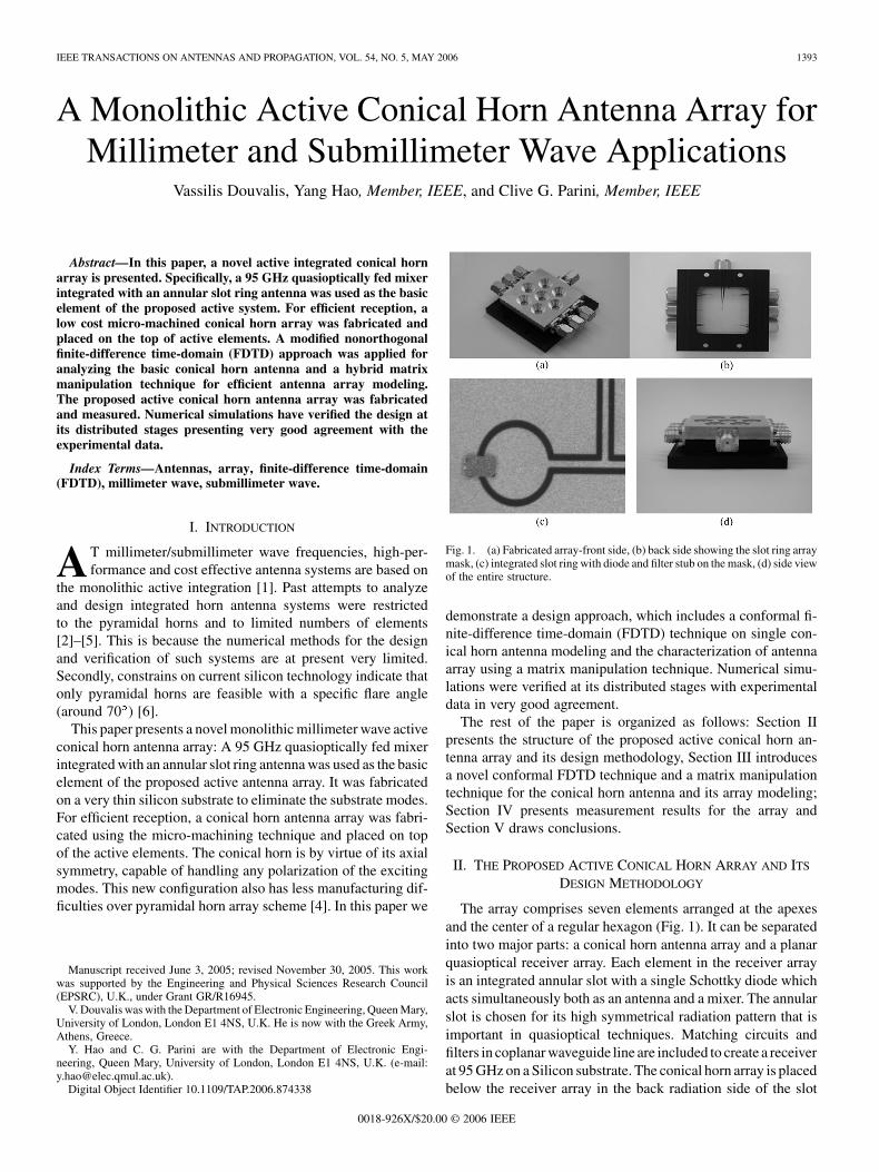
Fig. 1. (a) Fabricated array-front side, (b) back side showing the slot ring arraymask, (c) integrated slot ring with diode and filter stub on the mask, (d) side viewof the entire structure.
demonstrate a design approach, which includes a conformal fi-nite-difference time-domain (FDTD) technique on single con-ical horn antenna modeling and the characterization of antennaarray using a matrix manipulation technique. Numerical simu-lations were verified at its distributed stages with experimentaldata in very good agreement.
The rest of the paper is organized as follows: Section IIpresents the structure of the proposed active conical horn an-tenna array and its design methodology, Section III introducesa novel conformal FDTD technique and a matrix manipulationtechnique for the conical horn antenna and its array modeling;Section IV presents measurement results for the array andSection V draws conclusions.
II. THE PROPOSED ACTIVE CONICAL HORN ARRAY AND ITS
DESIGN METHODOLOGY
The array comprises seven elements arranged at the apexesand the center of a regular hexagon (Fig. 1). It can be separatedinto two major parts: a conical horn antenna array and a planarquasioptical receiver array. Each element in the receiver arrayis an integrated annular slot with a single Schottky diode whichacts simultaneously both as an antenna and a mixer. The annularslot is chosen for its high symmetrical radiation pattern that isimportant in quasioptical techniques. Matching circuits andfilters in coplanar waveguide line are included to create a receiverat 95 GHz on a Silicon substrate. The conical horn array is placedbelow the receiver array in the back radiation side of the slot
1394 IEEE TRANSACTIONS ON ANTENNAS AND PROPAGATION, VOL. 54, NO. 5, MAY 2006
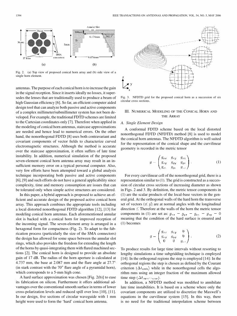
Fig. 2. (a) Top view of proposed conical horn array and (b) side view of asingle horn element.
antennas. The purpose of each conical horn is to increase the gainin the signal reception. Since it inserts ideally no losses, it super-sedes the lenses that are traditionally used to produce a beam ofhigh Gaussian efficiency [6]. So far, an efficient computer aideddesign tool that can analyze both passive and active componentsof a complex millimeter/submillimeter system has not been de-veloped. For example, the traditional FDTD schemes are limitedto the Cartesian coordinates only [7]. Therefore when applied inthe modeling of conical horn antennas, staircase approximationsare needed and hence lead to numerical errors. On the otherhand, the nonorthogonal FDTD [8] uses both contravariant andcovariant components of vector fields to characterize curvedelectromagnetic structures. Although the method is accurateover the staircase approximation, it often suffers of late timeinstability. In addition, numerical simulation of the proposedseven-element conical horn antenna array may result in an in-sufficient memory error on a typical personal computer. Also,very few efforts have been attempted toward a global analysistechnique incorporating both passive and active components[6], [9] and such efforts do not have a general applicability sincecomplexity, time and memory consumption are issues that canbe tolerated only when simple active structures are considered.
In this paper, a hybrid approach is proposed to achieve an ef-ficient and accurate design of the proposed active conical hornarray. This approach combines the appropriate tools includinga local distorted nonorthogonal FDTD algorithm [12], [13] formodeling conical horn antennas. Each aforementioned annularslot is backed with a conical horn for improved reception ofthe incoming signal. The seven-element array is arranged in ahexagonal form for compactness (Fig. 2). To adapt to the fab-rication process (particularly the size of the SMA connectors)the design has allowed for some space between the annular slotrings, which also provides the freedom for extending the lengthof the horns by quasi-integrating them with flared machined sec-tions [2]. The conical horn is designed to provide an absolutegain of 17 dB. The radius of the horn aperture is calculated at4.737 mm, the base at 2.087 mm and the flare angle at 27.7(in stark contrast with the 70 flare angle of a pyramidal horn),which corresponds to a 5-mm high cone.
A hard surface approximation was chosen [Fig. 2(b)] to easeits fabrication on silicon. Furthermore it offers additional ad-vantages over the conventional smooth surface in terms of lowercross-polarization levels and reduced spill over loss [10], [11].In our design, five sections of circular waveguide with 1 mmheight were used to form the ‘hard’ conical horn antenna.
Fig. 3. NFDTD grid for the proposed conical horn as a succession of sixcircular cross sections.
III. NUMERICAL MODELING OF THE CONICAL HORN AND
THE ARRAY
A. Single Element Design
A conformal FDTD scheme based on the local distortednonorthogonal FDTD (NFDTD) method [8] is used to modelthe conical horn antennas. The NFDTD algorithm is well suitedfor the representation of the conical shape and the curvilineargeometry is recorded in the metric tensor
(1)
For every curvilinear cell of the nonorthogonal grid, there is arepresentation similar to (1). The grid is constructed as a succes-sion of circular cross sections of increasing diameter as shownin Figs. 2 and 3. By definition, the metric tensor components in(1) are the scalar products of the local-base vectors in the gen-eral grid. At the orthogonal walls of the hard horn the transverseset of vectors are at normal angles with the longitudinaldirection . Therefore at the walls of the horn the metric tensorcomponents in (1) are set as:meaning that the condition of the hard surface is ensured and(1) becomes
(2)
To produce results for large time intervals without resorting tolengthy simulations a time subgridding technique is employed[14]: In the orthogonal regions the step is employed [14]: In theorthogonal regions the step is chosen as defined by the Courantcriterion while in the nonorthogonal cells the algo-rithm runs using an integer fraction of the maximum allowedtime step .
In addition, a NFDTD method was modified to annihilatelate time instabilities. It is based on a scheme where only thecovariant components are utilized to discretize the Maxwell’sequations in the curvilinear system [15]. In this way, thereis no need for the traditional interpolation scheme between
DOUVALIS et al.: MONOLITHIC ACTIVE CONICAL HORN ANTENNA ARRAY 1395
Fig. 4. Comparison of experimental and simulatedS -parameters for a scaledconical horn antenna at microwave frequencies.
Fig. 5. (a) Array elements, (b) element radiating in free space, (c) and (d)interaction between specific sets of elements used in the matrix manipulationmethod.
contravariant and covariant components, which is proven tobe a source of instabilities [16]. Moreover the abandonmentof the contravariant components provides even more com-puter memory and power utilization. To evaluate the merit ofnonorthogonal FDTD over the traditional staircase FDTD inthe simulation of conical horn antennas, Fig. 4 is shown. Itcompares the return loss of a scaled-up model, designed atlower frequencies, of the proposed conical horn antenna. Twosimulations have been performed. One uses the LD-NFDTDmethod (solid dotted line) and another uses the staircase FDTD(dashed line). Both results are compared with measurements(solid line) made in the laboratory. Fig. 4 reveals the reliabilityand accuracy of the LN-FDTD over the staircase approxima-tion. The latter clearly shows unphysical behavior (positivevalues of the parameters) at some frequencies in the rangeof 6.5–20 GHz, which result from numerical errors caused bythe staircase approximation.
B. Array Design
Since numerically efficient infinite array techniques are notapplicable, a new method based on the combination of FDTD al-gorithm with matrix manipulation techniques is used to predictarray performance [17]. It reduces the computational volumeto be simulated with FDTD by exploiting the symmetries in-herent in any array. Only a small part of the array is analyzed,yielding a matrix description of the coupling and radiation char-acteristics from which the synthesis of the entire array is goingto take place. Specifically, for the proposed conical horn arraygeometry shown in Fig. 5(a), the decomposed parts to be sim-ulated are shown in Fig. 5(b)–(d). The hexagonal geometry not
Fig. 6. Time snapshots (H-field) comparison of the array near field computedwith a full FDTD simulation and the Matrix method. The matrix method canproduce almost the same results with much less computer resources.
only provides compactness but also reduces the generation ofgrating lobes which otherwise would be present in the array be-cause of the large spacing between the elements. Therefore, theversatility of the array in its radiation characteristics (fixed orscanning beam) is enhanced.
The components shown in Fig. 5 stand for the couplinginteractions between elements stored in the form of a matrix.The radiation matrix obtained from the simulation of Fig. 5(b)is going to reproduce the radiation matrices of all the elements.Also, the scattering matrices of the rest of the elements are goingto be produced from the data acquired by the simulations ofFig. 5(c) and (d). This is because:
1) and will be the mirror images through the ver-tical axis of and correspondingly.
2) and will be the mirror images through the hor-izontal axis of and correspondingly.
The above symmetry properties are carried out by the matrixoperators of the matrix manipulation method. Having the radia-tion and scattering properties of all the elements the array perfor-mance can now be evaluated. The methodology is based on theassumption that second neighbors’ interaction can be ignored asnegligible. This is correct for the specific array, since the high di-rectivity of each horn determined by its aperture size and lengthwill diminish any higher-order couplings as a simple FDTD al-gorithm run can reveal. Nevertheless the matrix manipulationmethod can be extended even in cases where this assumptiondoes not apply. Fig. 6 shows the comparison between the fullFDTD simulation and the matrix manipulation technique. Thetime snapshots of the electric field in the near field area of thearray are shown for a specific setting (central element radiatingin phase and 10.5 dB above the other elements).
IV. MEASUREMENT RESULTS AND COMPARISON
WITH SIMULATION
The fabricated array in different views is shown in Fig. 1and it radiation patterns were measured at 93 and 95 GHz. Inessence, they are obtained from the different values of the gen-erated IF signal as the array is scanned at the E- and H-planes[Fig. 8(a)]. Therefore, these are not the usual antenna patternmeasurements but rather active measurements incorporating theoperation of the diodes.
1396 IEEE TRANSACTIONS ON ANTENNAS AND PROPAGATION, VOL. 54, NO. 5, MAY 2006
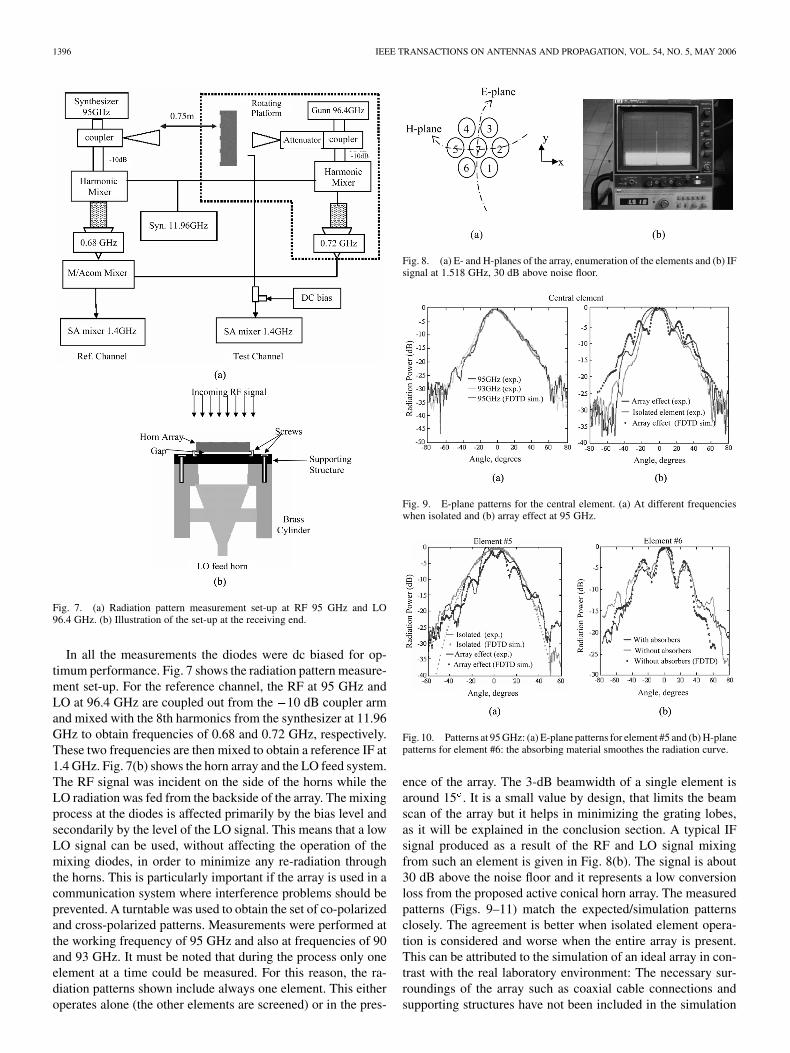
Fig. 7. (a) Radiation pattern measurement set-up at RF 95 GHz and LO96.4 GHz. (b) Illustration of the set-up at the receiving end.
In all the measurements the diodes were dc biased for op-timum performance. Fig. 7 shows the radiation pattern measure-ment set-up. For the reference channel, the RF at 95 GHz andLO at 96.4 GHz are coupled out from the 10 dB coupler armand mixed with the 8th harmonics from the synthesizer at 11.96GHz to obtain frequencies of 0.68 and 0.72 GHz, respectively.These two frequencies are then mixed to obtain a reference IF at1.4 GHz. Fig. 7(b) shows the horn array and the LO feed system.The RF signal was incident on the side of the horns while theLO radiation was fed from the backside of the array. The mixingprocess at the diodes is affected primarily by the bias level andsecondarily by the level of the LO signal. This means that a lowLO signal can be used, without affecting the operation of themixing diodes, in order to minimize any re-radiation throughthe horns. This is particularly important if the array is used in acommunication system where interference problems should beprevented. A turntable was used to obtain the set of co-polarizedand cross-polarized patterns. Measurements were performed atthe working frequency of 95 GHz and also at frequencies of 90and 93 GHz. It must be noted that during the process only oneelement at a time could be measured. For this reason, the ra-diation patterns shown include always one element. This eitheroperates alone (the other elements are screened) or in the pres-
Fig. 8. (a) E- and H-planes of the array, enumeration of the elements and (b) IFsignal at 1.518 GHz, 30 dB above noise floor.
Fig. 9. E-plane patterns for the central element. (a) At different frequencieswhen isolated and (b) array effect at 95 GHz.
Fig. 10. Patterns at 95 GHz: (a) E-plane patterns for element #5 and (b) H-planepatterns for element #6: the absorbing material smoothes the radiation curve.
ence of the array. The 3-dB beamwidth of a single element isaround 15 . It is a small value by design, that limits the beamscan of the array but it helps in minimizing the grating lobes,as it will be explained in the conclusion section. A typical IFsignal produced as a result of the RF and LO signal mixingfrom such an element is given in Fig. 8(b). The signal is about30 dB above the noise floor and it represents a low conversionloss from the proposed active conical horn array. The measuredpatterns (Figs. 9–11) match the expected/simulation patternsclosely. The agreement is better when isolated element opera-tion is considered and worse when the entire array is present.This can be attributed to the simulation of an ideal array in con-trast with the real laboratory environment: The necessary sur-roundings of the array such as coaxial cable connections andsupporting structures have not been included in the simulation
DOUVALIS et al.: MONOLITHIC ACTIVE CONICAL HORN ANTENNA ARRAY 1397
Fig. 11. Patterns at 93 GHz: (a) E-plane patterns for element #1 and (b) E-planeco- and cross-pol for element #3.
model. Even small details that cannot be predicted beforehand(such as the gap created by the screws binding the array toits support structure) permitted the integrated horn antennas tomove around two axes so that the E- and H-plane have beenproved to have an influence in the radiation pattern.
The effect of mutual coupling due to neighboring elementscan also be seen in the figures given. For example, in Fig. 10(a)the coupling effect for the edge element #5 is shown. In Fig. 9the same effect is depicted for the central element where theneighboring couplings are more. The use of absorber (similar towhat is used in an anechoic chamber) placed around the setupis important since it is seen to smooth out the radiation curvesignificantly [Fig. 10(b)]. There is also a great discrepancybetween the measured and simulated cross-polar patterns. Theamplitudes of the simulated data are consistently less than themeasured ones (at least in the range of 0 to 20 ). The highamplitude of the measured cross-polar patterns is attributedto the physical dimensions of the diodes as well as internalreflections/diffractions from the co-polar signal (Fig. 11).
V. CONCLUSION
A novel monolithic millimeter-wave two-dimensional activeconical horn array has been presented as a quasioptical receiverat 95 GHz. The designed resonant frequency was verified bythe measurements. The conical horn bears all the assets of otherhorn types (e.g., directivity, gain, etc.) and moreover predom-inates, by virtue of its axial symmetry, in the handling of anypolarization—especially the circular one. Because of its curvedshape, new simulation and fabrication techniques have to bedevised and this type of horn element has never before beenconsidered as a part of an integrated system. Conformal FDTDand matrix manipulation techniques combined with commercialsoftware have overcome existing design difficulties. The con-formal FDTD algorithm (LD-NFDTD) overcomes the problemsset by the traditional FDTD schemes which may be suitable forpyramidal horns but they fail in the simulation of cylindricalones. The matrix manipulation method provides a fast analysisof the array by exploiting a small part of it in order to predictits overall behavior. Also, the gain and efficiency of the antennaelements is no longer limited by the large horn flare angle of70 , which is associated with the anisotropic etching of silicon.The achievement of smaller flare angle increases dramatically
the freedom of the designer to choose the appropriate size ofthe horn and to manipulate its radiation characteristics (direc-tivity, gain, mutual coupling with other horns). In addition, theincreased directivity (3 dB beamwidth of a single element isat around 15 ) that the horns provide reduces to minimum thegrating lobe effects that would be present if annular slots wereused directly. This is because the inner-element spacing of theW-band array is more than three wavelengths. Ordinarily, suchsparse spacing leads to strong grating lobes in the pattern ifnarrow beamwidth elements are not combined with the slots.So, the scan of the array is limited by design to a few degrees,with a strong boresight beam and minimal grating lobes. Pat-tern measurements at 93 and 95 GHz agree well with the sim-ulation results. The proposed antenna array can be used eitherfor a fixed beam or scanning. Measurements on scanned beamperformance need a complex biasing network and results willbe presented in future publications. Although conversion losseshave not been calculated due to measurement restrictions, thehigh IF signals are indicative of generally low losses.
ACKNOWLEDGMENT
The authors would like to thank the Engineering and PhysicalSciences Research Council (EPSRC), U.K. for the financial sup-port of this project; the reviewers for their valuable comments;Prof. D. Olver for some useful discussions; Dr. B. Alderman,Dr. D. Matheson and Dr. P. Huggard from the Rutherford Ap-pleton Laboratory for the millimeter-wave horn array fabrica-tion and Mr. J. Dupuy for his effort on the millimeter-wavemeasurements.
REFERENCES
[1] Y. Qian and T. Itoh, “Progress in active integrated antennas and theirapplications,” IEEE Trans. Microw. Theory Tech., vol. 46, no. 11, pp.1891–1990, Nov. 1998.
[2] G. M. Rebeiz, L. P. B. Katehi, W. Y. Ali-Ahmad, G. V. Eleftheriades, andC. C. Ling, “Integrated horn antennas for millimeter-wave applications,”IEEE Antennas Propag. Mag., vol. 34, pp. 7–16, 1992.
[3] W. Y. Ali-Ahmad, C. C. Ling, and G. M. Rebeiz, “Two-dimensionaldual-polarized millimeter-wave horn antenna arrays,” in Proc. Antennasand Propagation Soc. Int. Symp., vol. 4, 1990, pp. 1429–1432.
[4] G. V. Eleftheriades and G. M. Rebeiz, “Design and analysis of quasiin-tegrated horn antennas for millimeter and submillimeter-wave applica-tions,” IEEE Trans. Microw. Theory Tech., vol. 41, pp. 954–965, 1993.
[5] , “Millimeter-wave integrated diagonal horn antennas,” in Antennasand Propagation Soc. Int. Symp. Digest, vol. 2, Jun. 1991, pp. 984–986.
[6] S. B. Yeap, M. Rayner, and C. Parini, “Global quasioptical simulationsof millimeter-wave receivers,” IEEE Microw. Wireless Comp. Lett., vol.14, pp. 478–480, 2004.
[7] K. S. Yee, “Numerical solution of initial boundary-value problems in-volving Maxwell’s equations in isotropic media,” IEEE Trans. AntennasPropag., vol. AP-14, pp. 302–307, May 1966.
[8] R. Holland, “Finite difference solutions of Maxwell’s equations in gen-eralized nonorthogonal coordinates,” IEEE Trans. Nucl. Sci., vol. NS-30,no. 6, pp. 4591–4689, Dec. 1983.
[9] M. Cryan, S. Helbing, F. Alimenti, P. Mezzanotte, L. Roselli, and R.Sorrentino, “Simulation and measurement of quasioptical multipliers,”IEEE Trans. Microw. Theory Tech., vol. 49, no. 3, pp. 451–464, Mar.2001.
[10] Y. Hao and C. J. Railton, “Analyzing electromagnetic structures withcurved boundaries on cartesian FDTD meshes,” IEEE Trans. Microw.Theory Tech., vol. 46, no. 1, pp. 82–88, Jan. 1998.
[11] Y. Hao, V. Douvalis, and C. G. Parini, “Modeling conical horn antennasusing local distorted nonorthogonal FDTD method,” in Proc. 12th Int.Symp. Antennas, vol. 1, France, 2002, pp. 67–70.
1398 IEEE TRANSACTIONS ON ANTENNAS AND PROPAGATION, VOL. 54, NO. 5, MAY 2006
[12] M. S. Aly and S. F. Mahmoud, “Propagation and radiation behavior of alongitudinally slotted horn with dielectric-filled slots,” Proc. Inst. Elect.Eng. Microwaves, Antennas and Propagation, vol. 132, pp. 477–479,1985.
[13] P.-S. Kildal and E. Lier, “Hard horns improve cluster feeds of satelliteantennas,” Electron. Lett., vol. 24, pp. 491–492, Apr. 1988.
[14] V. Douvalis, Y. Hao, and C. G. Parini, “Reduction of late time instabil-ities of the finite difference time domain method in curvilinear coordi-nates,” Proc. Inst. Elect. Eng. Science, Measurement and Technology,vol. 149, no. 5, pp. 267–272, Sep. 2002.
[16] S. D. Gedney and J. A. Roden, “Numerical stability of nonorthogonalFDTD methods,” IEEE Trans. Antennas Propag., vol. 48, no. 2, pp.231–239, Feb. 2000.
[17] V. Douvalis, Y. Hao, and C. G. Parini, “Fast array analysis using a com-bination of FDTD with matrix manipulation techniques,” Proc. Inst.Elect. Eng. Microwaves, Antennas and Propagation, vol. 152, no. 4, pp.258–264, Aug. 2005.
[18] V. Douvalis and Y. Hao, “A monolithic active conical horn antenna ar-rays for millimeter and sub-millimeter wave applications,” in Proc. IEEEAntennas Propag. Soc. Int. Symp., vol. 1, Jun. 2004, pp. 567–570.
Vassilis Douvalis was born in Athens, Greece, in1978. He received the B.Sc. and M.Sc. degrees inelectrical and electronic engineer from the NationalTechnical University of Athens, in 2000, and thePh.D. degree in electronic engineering from QueenMary College, University of London, London, U.K.,in 2005. His dissertation was on active antennaarrays.
From 2004 to 2005, he was employed as a Re-search Assistant on an Engineering and Physical Sci-ences Research Council (EPSRC), U.K., project con-
cerning photonic antennas and metamaterials. He is currently doing his nationalservice in Greece.
Yang Hao (M’99) received the Ph.D. degree from theCentre for Communications Research (CCR), Uni-versity of Bristol, Bristol, U.K. in 1998.
From 1998 to 2000, he was a Postdoctoral ResearchFellow at the School of Electrical and Electronic En-gineering, University of Birmingham, Birmingham,U.K. In May 2000, he joined the Antenna EngineeringGroup, Queen Mary College, University of London,London, U.K., first as a Lecturer and now a Reader inantenna and electromagnetics. He has co-edited onebook, contributed two book chapters, and published
over 60 technical papers. His research interests are computational electromag-netics, on-body radio propagations, active integrated antennas, electromagneticbandgap structures and microwave metamaterials.
Dr. Hao is a Member of the Institution of Electrical Engineers (IEE), London,U.K. He is also a member of Technical Advisory Panel of IEE Antennas andPropagation Professional Network and a member of Wireless Onboard Space-craft Working Group, ESTEC, ESA. He was a session organizer and Chair forvarious international conferences and also a keynote speaker at ANTEM 2005,France.
Clive G. Parini (M’96) received the B.Sc.(Eng.)and Ph.D. degrees from Queen Mary College,University of London, London, U.K., in 1973 and1976, respectively.
He then joined ERA Technology Ltd., U.K.,working on the design of microwave feeds and offsetreflector antennas. In 1977, he returned to QueenMary College and is currently Professor of AntennaEngineering and Heads the Communications Re-search Group. He has published over 100 paperson research topics including array mutual coupling,
array beam forming, antenna metrology, microstrip antennas, application ofmetamaterials, millimeterwave compact antenna test ranges, and millimeter-wave integrated antennas.
Prof. Parini is a Fellow of the Institution of Electrical Engineers (IEE),London, U.K. In January 1990, he was one of three co-workers to receivethe IEE Measurements Prize for work on near field reflector metrology. Heis currently the Chairman of the IEE Antennas and Propagation ProfessionalNetwork Executive Team and is an Honorary Editor of IEE ProceedingsMicrowaves, Antennas and Propagation. He has been on the organizingcommittee for a number of international conferences and in 1991 was the ViceChairman and in 2001 the Chairman of the IEE International Conference onAntennas and Propagation.