IEEE TRANSACTIONS ON COMMUNICATIONS, VOL. 60, NO. 7, JULY 2012 1953 Time-Reversal Division Multiple Access over Multi-Path Channels Feng Han, Student Member, IEEE, Yu-Han Yang, Student Member, IEEE, Beibei Wang, Member, IEEE, Yongle Wu, Member, IEEE, and K. J. Ray Liu, Fellow, IEEE Abstract—The multi-path effect makes high speed broadband communications a very challenging task due to the severe inter- symbol interference (ISI). By concentrating energy in both the spatial and temporal domains, time-reversal (TR) transmission technique provides a great potential of low-complexity energy- efficient communications. In this paper, a novel concept of time- reversal division multiple access (TRDMA) is proposed as a wireless channel access method based on its high-resolution spatial focusing effect. It is proposed to use TR structure in multi-user downlink systems over multi-path channels, where signals of different users are separated solely by TRDMA. Both the single-transmit-antenna scheme and its enhanced version with multiple transmit antennas are developed and evaluated in this paper. The system performance is investigated in terms of its effective signal-to-interference-plus-noise ratio (SINR), the achievable sum rate and the achievable rates with outage. And some further discussions regarding its advantage over conventional rake receivers and the impact of spatial correlations between users are given at the end of this paper. It is shown in both analytical and simulation results that desirable properties and satisfying performances can be achieved in the proposed TRDMA multi-user downlink system, which makes TRDMA a promising candidate for future energy-efficient low-complexity broadband wireless communications. Index Terms—Time Reversal, temporal focusing, spatial focus- ing, TRDMA. I. I NTRODUCTION T HE past decade has witnessed an unprecedent increase of demand for high speed wireless services, which neces- sitates the need for future broadband communications. When it comes to broadband, the resolution of perceiving multiple paths increases accordingly. In a rich scattering environment, the adverse multi-path effect makes conventional high-speed communications a very challenging task due to the severe inter-symbol interference (ISI). To resolve this problem, multi- carrier modulation (e.g. OFDM) and/or complicated equaliza- tion are needed [1]–[4] at the receiver to alleviate the ISI. Although the performance is well satisfactory, it often results in a prohibitively high complexity for end-user equipments and wireless terminals in many applications. Paper approved by D. I. Kim, the Editor for Spread Spectrum Transmission and Access of the IEEE Communications Society. Manuscript received August 12, 2011; revised January 4, 2012. F. Han, Y.-H. Yang, and K. J. R. Liu are with the Department of Electrical and Computer Engineering, University of Maryland, College Park, MD, 20742 USA (e-mail: {hanf, yhyang, kjrliu}@umd.edu). B. Wang and Y. Wuare with Qualcomm Inc., San Diego, CA, 92121, USA (e-mail: {beibeiw, yonglew}@qualcomm.com). Digital Object Identifier 10.1109/TCOMM.2012.051012.110531 On the other hand, time-reversal (TR) signal transmission technique can provide a great potential of low-complexity energy-efficient communications[5], which can make full use of the nature of multi-path environments. The history of research on time-reversal transmission technology dates back to early 1990’s[6]–[10]; however, not much development and interest went beyond the acoustics and ultrasound domains at that time. As found in acoustic physics [6]–[10] and then further validated in practical underwater propagation environments[11]–[13], the energy of the TR acoustic waves from transmitters could be refocused only at the intended location with very high spatial resolution (several-wavelength level). Since TR can make full use of multi-path propagation and also requires no complicated channel processing and equalization, it was later verified and tested in wireless radio communication systems, especially in Ultra-wideband (UWB) systems[14]–[18]. The single-user TR wireless communications consist of two phases: the recording phase and the transmission phase. When transceiver A wants to transmit information to transceiver B, transceiver B first sends an impulse that propagates through a scattering multi-path environment and the multi-path signals are received and recorded by transceiver A; then, transceiver A simply transmits the time-reversed (and conjugated) waves back through the communication link to transceiver B. By utilizing channel reciprocity[19], the TR waves can retrace the incoming paths, ending up with a “spiky” signal-power spatial distribution focused only at the intended location, as commonly referred to as spatial focusing effect[5][17]. Also, from a signal processing point of view, in single-user commu- nications, TR essentially leverages the multi-path channel as a facilitating matched filter computing machine for the intended receiver, and concentrates the signal energy in the time domain as well, as commonly referred to as temporal focusing effect. It is worth noting that when the channel coherent time is not very small, the transmission phase of a duty cycle can include multiple transmissions of signals without requiring probing the channel before each transmission, which can reasonably maintain the bandwidth efficiency. It is typically the case when TR is used, and was verified by real-life experiments in [5]. In the single-user case, the temporal and spatial focusing effects have been shown to greatly simplify the receiver[14]– [18], [23], [24], and reduce power consumption and interfer- ence while maintaining the quality of service (QoS)[5]. In this paper, we consider a multi-user downlink system over multi-path channels, and propose a concept of time-reversal 0090-6778/12$31.00 c 2012 IEEE
Transcript
IEEE TRANSACTIONS ON COMMUNICATIONS, VOL. 60, NO. 7, JULY 2012 1953
Feng Han, Student Member, IEEE, Yu-Han Yang, Student Member, IEEE, Beibei Wang, Member, IEEE,Yongle Wu, Member, IEEE, and K. J. Ray Liu, Fellow, IEEE
Abstract—The multi-path effect makes high speed broadbandcommunications a very challenging task due to the severe inter-symbol interference (ISI). By concentrating energy in both thespatial and temporal domains, time-reversal (TR) transmissiontechnique provides a great potential of low-complexity energy-efficient communications. In this paper, a novel concept of time-reversal division multiple access (TRDMA) is proposed as awireless channel access method based on its high-resolutionspatial focusing effect. It is proposed to use TR structure inmulti-user downlink systems over multi-path channels, wheresignals of different users are separated solely by TRDMA. Boththe single-transmit-antenna scheme and its enhanced versionwith multiple transmit antennas are developed and evaluatedin this paper. The system performance is investigated in termsof its effective signal-to-interference-plus-noise ratio (SINR), theachievable sum rate and the achievable rates with outage.And some further discussions regarding its advantage overconventional rake receivers and the impact of spatial correlationsbetween users are given at the end of this paper. It is shown inboth analytical and simulation results that desirable propertiesand satisfying performances can be achieved in the proposedTRDMA multi-user downlink system, which makes TRDMA apromising candidate for future energy-efficient low-complexitybroadband wireless communications.
Index Terms—Time Reversal, temporal focusing, spatial focus-ing, TRDMA.
I. INTRODUCTION
THE past decade has witnessed an unprecedent increase ofdemand for high speed wireless services, which neces-
sitates the need for future broadband communications. Whenit comes to broadband, the resolution of perceiving multiplepaths increases accordingly. In a rich scattering environment,the adverse multi-path effect makes conventional high-speedcommunications a very challenging task due to the severeinter-symbol interference (ISI). To resolve this problem, multi-carrier modulation (e.g. OFDM) and/or complicated equaliza-tion are needed [1]–[4] at the receiver to alleviate the ISI.Although the performance is well satisfactory, it often resultsin a prohibitively high complexity for end-user equipmentsand wireless terminals in many applications.
Paper approved by D. I. Kim, the Editor for Spread Spectrum Transmissionand Access of the IEEE Communications Society. Manuscript received August12, 2011; revised January 4, 2012.
F. Han, Y.-H. Yang, and K. J. R. Liu are with the Department of Electricaland Computer Engineering, University of Maryland, College Park, MD, 20742USA (e-mail: {hanf, yhyang, kjrliu}@umd.edu).
B. Wang and Y. Wu are with Qualcomm Inc., San Diego, CA, 92121, USA(e-mail: {beibeiw, yonglew}@qualcomm.com).
Digital Object Identifier 10.1109/TCOMM.2012.051012.110531
On the other hand, time-reversal (TR) signal transmissiontechnique can provide a great potential of low-complexityenergy-efficient communications[5], which can make full useof the nature of multi-path environments. The history ofresearch on time-reversal transmission technology dates backto early 1990’s[6]–[10]; however, not much development andinterest went beyond the acoustics and ultrasound domainsat that time. As found in acoustic physics [6]–[10] andthen further validated in practical underwater propagationenvironments[11]–[13], the energy of the TR acoustic wavesfrom transmitters could be refocused only at the intendedlocation with very high spatial resolution (several-wavelengthlevel). Since TR can make full use of multi-path propagationand also requires no complicated channel processing andequalization, it was later verified and tested in wireless radiocommunication systems, especially in Ultra-wideband (UWB)systems[14]–[18].
The single-user TR wireless communications consist of twophases: the recording phase and the transmission phase. Whentransceiver A wants to transmit information to transceiver B,transceiver B first sends an impulse that propagates through ascattering multi-path environment and the multi-path signalsare received and recorded by transceiver A; then, transceiverA simply transmits the time-reversed (and conjugated) wavesback through the communication link to transceiver B. Byutilizing channel reciprocity[19], the TR waves can retracethe incoming paths, ending up with a “spiky” signal-powerspatial distribution focused only at the intended location, ascommonly referred to as spatial focusing effect[5][17]. Also,from a signal processing point of view, in single-user commu-nications, TR essentially leverages the multi-path channel as afacilitating matched filter computing machine for the intendedreceiver, and concentrates the signal energy in the time domainas well, as commonly referred to as temporal focusing effect.It is worth noting that when the channel coherent time is notvery small, the transmission phase of a duty cycle can includemultiple transmissions of signals without requiring probingthe channel before each transmission, which can reasonablymaintain the bandwidth efficiency. It is typically the case whenTR is used, and was verified by real-life experiments in [5].
In the single-user case, the temporal and spatial focusingeffects have been shown to greatly simplify the receiver[14]–[18], [23], [24], and reduce power consumption and interfer-ence while maintaining the quality of service (QoS)[5]. Inthis paper, we consider a multi-user downlink system overmulti-path channels, and propose a concept of time-reversal
1954 IEEE TRANSACTIONS ON COMMUNICATIONS, VOL. 60, NO. 7, JULY 2012
division multiple access (TRDMA) as a wireless channelaccess method by taking advantage of the high-resolutionspatial focusing effect of time-reversal structure. In principle,the mechanisms of reflection, diffraction and scattering inwireless medium give rise to the uniqueness and independenceof the multi-path propagation profile of each communicationlink[19], which are exploited to provide spatial selectivity inspatial division multiple access (SDMA) schemes. Comparedwith conventional antenna-array based beamforming SDMAschemes, time-reversal technique makes full use of a largenumber of multi-paths and in essence treats each path as avirtual antenna that naturally exists and is widely distributedin environments.
Thus, with even just one single transmit antenna, timereversal can potentially achieve a very high diversity gainand high-resolution “pin-point” spatial focusing. The high-resolution spatial focusing effect maps the natural multi-pathpropagation profile into a unique location-specific signaturefor each link, as an analogy to the artificial “orthogonal ran-dom code” in a code-division system. The proposed TRDMAscheme exploits the uniqueness and independence of location-specific signatures in multi-path environment, providing anovel low-cost energy-efficient solution for SDMA. Betteryet, the TRDMA scheme accomplishes much higher spatial-resolution focusing/selectivity and time-domain signal-energycompression at once, without requiring further equalization atthe receiver as the antenna-array based beamforming does.
The potential and feasibility of applying time reversal tomulti-user UWB communications were validated by somereal-life antenna-and-propagation experiments in[5], [20]–[22], in which the signal transmit power reduction and inter-user interference alleviation as a result of spatial focus-ing effect were tested and justified for one simplified one-shot transmission over deterministic multi-path ultra-widebandchannels. The idea of TRDMA proposed in this paper wasfurther supported by several important recent works [23]–[25].[23] introduced a TR-based single-user spatial multiplexingscheme for SIMO UWB system, in which multiple datastreams are transmitted through one transmit antenna andreceived by a multi-antenna receiver. Solid simulation resultsregarding bit-error-ratio (BER) demonstrate the feasibility ofapplying TR to spatially multiplex data streams. Following[23], [24] took into account the spatial correlation betweenantennas of the single receiver and numerically investigatedthrough computer simulation its impact to BER performance.Based on [23] and [24], [25] tackled a multiuser UWBscenario with a focus on the impact of channel correlationto the BER performance through simulation. However, thereis not much theoretical characterization or proof about systemperformances found in any of these papers. Furthermore, mostof these literatures focus only on BER performances, withoutlooking at the spectral efficiency which is one of the maindesign purposes for any spatial multiplexing scheme. Thereis still a lack of system-level theoretical investigation andcomprehensive performance analysis of a TR-based multi-user communications system in the literature. Motivated bythe high-resolution spatial focusing potential of the time-reversal structure, existing experimental measurements andsupporting literatures, several major developments have been
proposed and considered in the proposed TRDMA multi-usercommunications system. Specifically:
• We propose the concept of TRDMA as a novel multi-userdownlink solution for wireless multi-path environments,and developed a theoretical analysis framework for theproposed scheme.
• We consider a multi-user broadband communication sys-tem over multi-path Rayleigh fading channels, in whichthe signals of multiple users are separated solely byTRDMA.
• We define and evaluate a number of system performancemetrics, including the effective SINR at each user, achiev-able sum rate, and achievable rate with ε−outage.
• We further investigate the achievable rate region for asimplified two-user case, from which one can see theadvantages of TRDMA over its counterpart techniques,due to TR’s spatial focusing effect.
• We incorporate and examine quantitatively the impact ofspatial correlation of users to system performances for theSISO case to gain more comprehensive understanding ofTRDMA.
The rest of this paper is organized as follows. In Section II,we introduce the channel model and the proposed TRDMAmulti-user downlink systems with both a single transmitantenna and multiple antennas. Then, we analyze the effectiveSINR in Section III. In Section IV, both achievable sum rateand ε−outage rate are evaluated. Also in Section IV, a two-user case achievable rate region is characterized and comparedwith the rake-receiver counterparts. In Section V, the impact ofspatial correlation between users is investigated and discussed.Finally, conclusions are drawn in Section VI.
II. SYSTEM MODEL
In this section, we introduce the channel and system modeland the proposed TRDMA schemes. We begin with theassumptions and formulations of the channel model. Then, wedescribe the two phases of the basic TRDMA scheme with asingle transmit antenna. Finally, we extend the basic single-input-single-output (SISO) scheme to an enhanced multiple-input-single-output (MISO) TRDMA scheme with multipletransmit antennas at the base station (BS).
A. Channel Model
In this paper, we consider a multi-user downlink networkover multi-path Rayleigh fading channels. We first look ata SISO case where the base station (BS) and all users areequipped with a single antenna. The channel impulse response(CIR) of the communication link between the BS and the i-thuser is modeled as
hi[k] =
L−1∑l=0
hi,lδ[k − l], (1)
where hi[k] is the k-th tap of the CIR with length L, andδ[·] is the Dirac delta function. For each link, we assume thathi[k]’s are independent circular symmetric complex Gaussian(CSCG) random variables with zero mean and variance
E[|hi[k]|2] = e−kTS
σT , 0 � k � L− 1 (2)
HAN et al.: TIME-REVERSAL DIVISION MULTIPLE ACCESS OVER MULTI-PATH CHANNELS 1955
... ...... ... ... ... ... ...
...
1TRM g
2TRM g
TRM Ng
...
1h
Nh
2h
1~n
2~n
Nn~
1a
2a
Na
1X
2X
NX
1Y
2Y
NY
][1DX
][DNX
][2DX
][1DY
][2DY
][DNY
Fig. 1. The diagram of SISO TRDMA multiuser downlink system.
where TS is the sampling period of this system such that1/TS equals the system bandwidth B, and σT is the rootmean square (rms) delay spread[3] of the channel. Due to thetwo-phase nature of TR structure, we assume that channelsare reciprocal, ergodic and blockwise-constant with their tapvalues remaining fixed during at least one duty cycle. Eachduty cycle consists of the recording phase and the transmissionphase, which occupy the proportions of (1 − η) and η of thecycle period, with η ∈ (0, 1) depending on how fast channelsvary over time.
We first assume that the CIRs associated with different usersare uncorrelated. While realistic CIRs might not be perfectlyuncorrelated, this assumption greatly simplifies the analysiswhile capturing the essential idea of TRDMA. Moreover, real-life experimental results in [5], [17] show that in a rich-scattering environment the correlation between CIRs associ-ated with different locations decreases to a neglectable levelwhen two locations are even just several wave-lengths apart.A further discussion on the impact of the channel correlationbetween users to the system performance will be addressed inSection V.
B. Phase 1: Recording Phase
The block diagram of a SISO TRDMA downlink systemis shown in Fig. 1, in which there are N users receiving sta-tistically independent messages {X1(k), X2(k), · · · , XN (k)}from the BS, respectively. The time-reversal mirror (TRM)shown in the diagram is a device that can record andtime-reverse (and conjugate if complex-valued) the receivedwaveform, which will be used to modulate the time-reversedwaveform with input signal by convolving them together inthe following transmission phase.
During the recoding phase, the N intended users first taketurns to transmit an impulse signal to the BS (ideally it canbe a Dirac δ−function, but in practice a modified raise-cosinesignal can be a good candidate for limited bandwidth forthis purpose[5]). Meanwhile, the TRMs at the BS record thechannel response of each link and store the time-reversedand conjugated version of each channel response for thetransmission phase. For simplicity of analytical derivation, weassume in our analysis that the waveform recorded by TRMreflects the true CIR, ignoring the small corruption caused bythermal noise and quantization noise. Such a simplificationwas justified and based on the following facts shown inliteratures of time reversal:
• The thermal noise (typically modeled as additive whiteGaussian noise (AWGN)) can be effectively reduced to a
desired level by averaging multiple recorded noisy sam-ples of the same CIR’s, provided that channels are slow-varying, as shown in the real-life experiments [5]. Thiswould increase the portion (1−η) of the recording phasein the entire duty cycle, leading to a increased channelprobing overhead; but the structure of the analysis for theproposed system is not altered.
• The effect of quantization was studied by [26]. It wasshown that a nine-bit quantization can be treated asnearly perfect for most applications; and even with one-bit quantization, the TR system can work reasonably well,demonstrating the robustness of the TR-based transmis-sion technique.
C. Phase 2: Transmission Phase
After the channel recording phase, the system starts itstransmission phase. At the BS, each of {X1, X2, · · · , XN}represents a sequence of information symbols that are indepen-dent complex random variables with zero mean and varianceof θ. In other words, we assume that for each i from 1 toN , Xi[k] and Xi[l] are independent when k �= l. As wementioned earlier, any two sequences of {X1, X2, · · · , XN}are also independent in our model. We introduce the rate back-off factor D as the ratio of the sampling rate to the baud rate,by performing up-sampling and down-sampling with a factorD at the BS and receivers as shown in Fig. 1. Such a notion ofback-off factor facilitates simple rate conversion in the analysisof a TR system.
These sequences are first up-sampled by a factor of D atthe BS, and the i-th up-sampled sequence can be expressedas
X[D]i [k] =
{Xi[k/D], if k mod D = 0,
0, if k mod D �= 0.(3)
Then the up-sampled sequences are fed into the bank of TRMs{g1, g2, · · · , gN}, where the output of the i-th TRM gi is the
convolution of the i-th up-sampled sequence{X
[D]i [k]
}and
the TR waveform {gi[k]} as shown in Fig. 1, with
gi[k] = h∗i [L− 1− k]
/√√√√E
[L−1∑l=0
|hi[l]|2], (4)
which is the normalized (by the average channel gain) complexconjugate of time-reversed {hi[k]}. After that, all the outputsof TRM bank are added together, and then the combined signal{S[k]} is transmitted into wireless channels with
S[k] =N∑i=1
(X
[D]i ∗ gi
)[k]. (5)
In essence, by convolving the information symbol sequenceswith TR waveforms, TRM provides a mechanism of embed-ding the unique location-specific signature associated witheach communication link into the transmitted signal for theintended user.
The signal received at user i is represented as follows
Y[D]i [k] =
N∑j=1
(X
[D]j ∗ gj ∗ hi
)[k] + ni[k], (6)
1956 IEEE TRANSACTIONS ON COMMUNICATIONS, VOL. 60, NO. 7, JULY 2012
...
......
... ... ... ...
...
g N
1 1a
2a
Na
1X
NX
1Y
2Y
NY
][1DX
][DNX
][1DY
][2DY
][DNY
...
...
......
...
...
g 1
1
g TM
N
g TM
1
TM
][1DX
][1DX
][DNX
][DNX
Fig. 2. The diagram of MISO TRDMA multiuser downlink system.
which is the convolution of the transmitted signal {S[k]}and the CIR {hi[k]}, plus an additive white Gaussian noisesequence {ni[k]} with zero mean and variance σ2.
Thanks to the temporal focusing effect, the signal energy isconcentrated in a single time sample. The i-th receiver (user i)simply performs a one-tap gain adjustment ai to the receivedsignal to recover the signal and then down-samples it withthe same factor D, ending up with Yi[k] given as follows (fornotational simplicity, L− 1 is assumed to be a multiple of D)
Yi[k] = ai
N∑j=1
(2L−2)/D∑l=0
(hi ∗ gj)[Dl]Xj [k − l] + aini[k], (7)
where
(hi ∗gj)[k] =L−1∑l=0
hi[l]gj [k− l] =
L−1∑l=0
hi[l]h∗j [L− 1− k + l]√
E
[L−1∑l=0
|hj [l]|2] (8)
with k = 0, 1, · · · , 2L − 2, and ni[k] = ni[Dk], which isAWGN with zero mean and variance σ2.
D. TRDMA with multiple transmit antennas
In this part, we generalize the basic TRDMA scheme into anenhanced version with multiple transmit antennas. To maintainlow complexity at receivers, we consider a MISO case wherethe transmitting BS is equipped with MT antennas togetherwith multiple single-antenna users.
Let h(m)i [k] denote the k-th tap of the CIR for the commu-
nication link between user i and the m-th antenna of the BS,and we assume it is a circular symmetric complex Gaussianrandom variable with zero mean and a variance
E[|h(m)i [k]|2] = e
− kTSσT . (9)
In alignment with the basic SISO case, we also assume thatpaths associated with different antennas are uncorrelated, i.e.h(m)i [k] and h
(w)j [l] are uncorrelated for ∀ i, j ∈ {1, 2, · · · , N}
and ∀ k, l ∈ {0, 1, · · · , L − 1} when m �= w, where m,w ∈{1, 2, · · · ,MT } are the indices of the m-th and w-th antennasat the BS.
For the MISO TRDMA scheme, each antenna at the BSplays a role similar to the single-antenna BS in the basicscheme. The block diagram for the MISO TRDMA is shownin Fig. 2. The TR waveform {g(m)
i [k]} is the normalized (by
the average total energy of MISO channels) complex conjugateof time-reversed {h(m)
i [k]}, i.e.
g(m)i [k] = h
(m)∗i [L− 1− k]
/√√√√E
[MT
L−1∑l=0
|h(m)i [l]|2
]. (10)
As a result, the average total transmit power at the BS is
P =N × θ
D, (11)
which does not depend on the number of the transmit antennasMT .
The resulting received signal at user i can be similarlyrepresented as
Yi[k] =N∑
j=1
MT∑m=1
2L−2D∑
l=0
(h(m)i ∗ g(m)
j
)[Dl]Xj [k − l] + n[k], (12)
where n[k] is additive white Gaussian noise with zero meanand variance σ2.
Hereafter, we define a modified received signal-to-noiseratio (SNR) ρ for the
ρ =P
σ2E
[L−1∑l=0
|h(m)i [l]|2
]=
P
σ2
1− e−LTS
σT
1− e− TS
σT
, (13)
to rule out the potential multi-path gain in the system modelin the following performance evaluations.
In the following sections, we evaluate the system per-formance of the proposed system in terms of the effectiveSINR, the achievable sum rate, and the achievable rates withε−outage.
III. EFFECTIVE SINR
In this section, we evaluate the effective SINR of theproposed system. Since the basic SISO scheme is just a specialcase with MT = 1, we analyze the general MISO case withMT as a parameter in this section.
Note that for{(h
(m)i ∗ g(m)
j )[k]}
in (12), when k = L− 1
and j = i, it corresponds to the maximum-power central peakof the autocorrelation function, i.e.
(h(m)i ∗g(m)
i )[L−1]=
L−1∑l=0
|h(m)i [l]|2
/√√√√E
[MT
L−1∑l=0
|h(m)i [l]|2
]. (14)
Subject to the constraint of one-tap receivers, the i-th receiveris designed to estimate Xi[k − L−1
D ] solely based on theobservation of Yi[k]. Then, the remaining components of Yi
can be further categorized into inter-symbol interference (ISI),inter-user interference (IUI) and noise, as shown below:
Yi[k] = ai
MT∑m=1
(h(m)i ∗ g(m)
i )[L− 1]Xi[k − L− 1
D] (Signal)
+ ai
(2L−2)/D∑l=0
l �=(L−1)/D
MT∑m=1
(h(m)i ∗ g(m)
i )[Dl]Xi[k − l] (ISI)
+ ai
N∑j=1
j �=i
(2L−2)/D∑l=0
MT∑m=1
(h(m)i ∗ g(m)
j )[Dl]Xj [k − l] (IUI)
+ aini[k]. (Noise)(15)
HAN et al.: TIME-REVERSAL DIVISION MULTIPLE ACCESS OVER MULTI-PATH CHANNELS 1957
Note that the one-tap gain ai does not affect the effectiveSINR, we consider it as ai = 1 in the subsequent analysis,without loss of generality.
Given a specific realization of the random CIRs, from (15),one can calculate the signal power PSig(i) as
PSig(i) = EX
⎡⎣∣∣∣∣∣MT∑m=1
(hi ∗ gi)[L− 1]Xi[k − L− 1
D]
∣∣∣∣∣2⎤⎦ (16)
= θ
∣∣∣∣∣MT∑m=1
(h(m)i ∗ g(m)
i
)[L− 1]
∣∣∣∣∣2
,
where EX [·] represents the expectation over X. Accordingly,the powers associated with ISI and IUI can be derived as
PISI(i) = θ
2L−2D∑
l=0
l �=L−1D
∣∣∣∣∣MT∑m=1
(h(m)i ∗ g(m)
i
)[Dl]
∣∣∣∣∣2
, (17)
PIUI(i) = θ
N∑j=1
j �=i
2L−2D∑l=0
∣∣∣∣∣MT∑m=1
(h(m)i ∗ g(m)
j
)[Dl]
∣∣∣∣∣2
. (18)
When there exists interference, the SINR is almost alwaysa crucial performance metric used to measure the extent towhich a signal is corrupted. It is especially the case for amedia-access scheme, where interference management is oneof the main design objectives. In this part, we investigate theeffective SINR at each user in this multi-user network.
We define the average effective SINR at user i SINRavg(i)as the ratio of the average signal power to the averageinterference-and-noise power, i.e.,
SINRavg(i) =E [PSig(i)]
E [PISI(i)] + E [PIUI(i)] + σ2, (19)
where each term has been specified in (16), (17) and (18). Notethat such defined effective SINR in (19) bears difference withthe quantity E
[PSig(i)
PISI(i)+PIUI (i)+σ2
]in general. The former
can be treated as an approximation of the latter quantity. Suchan approximation is especially useful when the calculation ofthe average SINR using multiple integration is too complex, asis the case in this paper and literatures such as [18], [28], [29].The performance of this approximation will be demonstratedin the numerical results shown in Figures 3, 4 and 5.
Theorem 1. For the independent multi-path Rayleigh fadingchannels given in Section II, the expected value of each termfor the average effective SINR (19) at user i can be obtainedas shown in (20), (21), and (22).
Proof: Based on the channel model presented in SectionII, the second and fourth moments of h(m)
i [k] are given by[36]
E[|h(m)
i [k]|2]= e
−kTSσT , (23)
E[|h(m)
i [k]|4]= 2
(E[|h(m)
i [k]|2])2
= 2e− 2kTS
σT . (24)
Based on (23) and (24), after some basic mathematical deriva-tions, we obtain the following expected values for ∀i ∈{1, 2, · · · , N} in (25), (26), and (27).
Therefore, according to (16-18), (20-22) are obtained asshown in Theorem 1.
From Theorem 1, one can see that the average interferencepowers (i.e. ISI and IUI) in (26) and (27) do not depend onMT , while the signal power level in (25) increases linearlywith the number of antennas, which is due to an enhancedfocusing capability with multiple transmit antennas leveragingthe multi-paths in the environment. The enhanced focusingeffects monotonically improve the effective SINR. Anotherinteresting observation is that a larger back-off factor D yieldshigher reception quality of each symbol, which is especiallyeffective in the high SINR regime where interference powerdominates the noise power. The asymptotic behavior of theSINR in the high SNR regime with varying D is given by thefollowing theorem.
Theorem 2. In the high SNR regime, when D is smallsuch that D � L and D � σT /TS, doubling D leads toapproximately a 3dB gain in the average effective SINR.
Proof: First note that the signal power does not dependon D and that the noise is negligible in the high SINR regime.Thus, we can focus on the interference powers.• For Inter-Symbol Interference (ISI):
E [PISI(i,D = d)]
E [PISI(i,D = 2d)]=
(1 + e
− dTSσT
)(1− e
− (L−2+d)TSσT
)(1− e
− (L−2+2d)TSσT
) (28)
Since D � L, then
(1−e
− (L−2+d)TSσT
)(1−e
− (L−2+2d)TSσT
) ≈ 1; and since D �
σT
TS, then e
−dTSσT ≈ 1. Therefore,
E [PISI(i,D = d)]
E [PISI(i,D = 2d)]≈ 2.
• For Inter-User Interference (IUI):E [PIUI(i,D = d)]
E [PIUI(i,D = 2d)]=
(1 + e
− dTSσT
)× (29)(
1 + e− dTS
σT
)(1 + e
− 2LTSσT
)− 2e
− (L+1)TSσT
(1 + e
− (d−2)TSσT
)(1 + e
− 2dTSσT
)(1 + e
− 2LTSσT
)− 2e
− (L+1)TSσT
(1 + e
− (2d−2)TSσT
) .
For similar reasons,
E [PIUI(i,D = d)]
E [PIUI(i,D = 2d)]≈ 2.
Next, we present some numerical evaluation of the averageeffective SINR. In this paper, we mainly consider the broad-band systems with frequency bandwidth that typically rangesfrom hundreds MHz to several GHz, which is much wider thatthose narrow-band systems specified in 3GPP/3GPP2. In therich scattering environment, the underlying paths are so manythat the number of perceived multiple paths increases quicklywith the system bandwidth. For a system with bandwidth B,the minimum resolvable time-difference between two pathsis TS = 1/B[4]. Keeping this in mind, we first chooseL = 257 and σT = 128TS from a typical range, and
1958 IEEE TRANSACTIONS ON COMMUNICATIONS, VOL. 60, NO. 7, JULY 2012
E [PSig(i)] = θ1 + e
−LTSσT
1 + e− TS
σT
+ θMT1− e
−LTSσT
1− e− TS
σT
; (20)
E [PISI(i)] = 2θ
e− TS
σT
(1− e
− (L−2+D)TSσT
)(1− e
−DTSσT
)(1 + e
− TSσT
) ; (21)
E [PIUI(i)] = θ(N − 1)
(1 + e
−DTSσT
)(1 + e
− 2LTSσT
)− 2e
− (L+1)TSσT
(1 + e
− (D−2)TSσT
)(1− e
−DTSσT
)(1 + e
− TSσT
)(1− e
−LTSσT
) . (22)
E
⎡⎣∣∣∣∣∣MT∑m=1
(h(m)i ∗ g(m)
i
)[L− 1]
∣∣∣∣∣2⎤⎦ =
1 + e−LTS
σT
1 + e− TS
σT
+MT1− e
−LTSσT
1− e− TS
σT
; (25)
E
⎡⎢⎢⎢⎣2L−2
D∑l=0
l �=L−1D
∣∣∣∣∣MT∑m=1
(h(m)i ∗ g(m)
i
)[Dl]
∣∣∣∣∣2
⎤⎥⎥⎥⎦ = 2
e− TS
σT
(1− e
− (L−2+D)TSσT
)(1− e
−DTSσT
)(1 + e
− TSσT
) , (26)
E
⎡⎢⎣ N∑j=1j �=i
2L−2D∑
l=0
∣∣∣∣∣MT∑m=1
(h(m)j ∗ g(m)
i
)[Dl]
∣∣∣∣∣2⎤⎥⎦ = (N − 1)
(1 + e
−DTSσT
)(1 + e
− 2LTSσT
)− 2e
− (L+1)TSσT
(1 + e
− (D−2)TSσT
)(1− e
−DTSσT
)(1 + e
− TSσT
)(1− e
−LTSσT
) . (27)
−10 −5 0 5 10 15 20−10
−5
0
5
10
15
Ave
rag
e E
ffec
tive
SIN
R (
dB
)
(dB)
Simulation ResultsTheoretical Results
MT=8
MT=4
MT=2
MT=1
MT=16
Fig. 3. The impact of the number of antennas when D = 8, N = 5.
evaluate the average effective SINR versus ρ under varioussystem configurations in terms of N (the number of users),MT (the number of antennas) and D (the rate back-offfactor). In Fig. 3, Fig. 4 and Fig. 5, with L = 257 andσT = 128TS, the solid curves are obtained according to theanalytical results given by Theorem 1, and the dashed curvesare collected from simulation which numerically computesE[
PSig(i)PISI (i)+PIUI(i)+σ2
]. One can see that the results shown
in Theorem 1 approximate well the empirical means obtainedby simulation, which demonstrates the effectiveness of the
−10 −5 0 5 10 15 20−15
−10
−5
0
5
10
15
(dB)
Ave
rag
e E
ffec
tive
SIN
R (
dB
)
Simulation ResultsTheoretical Results
D=1
D=2
D=4
D=8
D=16
Fig. 4. The impact of the rate back-off factor when N = 5, MT = 4.
definition of effective SINR in the system of interest in thispaper.
Fig. 3 is plotted with D = 8 and N = 5, demonstrating theimpact of the number of antennas MT to the effective SINR.From Fig. 3, one can see that approximately a 3dB gain isattained as MT is doubled within a reasonable range. Theimpact of the rate back-off to the effective SINR is shownwith N = 5, MT = 4 in Fig. 4. Both analytical formulasand simulation results show that a lager D can reduce ISIand IUI while maintaining the signal power. In the high SNRregime where interference powers dominates the noise power,
HAN et al.: TIME-REVERSAL DIVISION MULTIPLE ACCESS OVER MULTI-PATH CHANNELS 1959
−10 −5 0 5 10 15 20−6
−4
−2
0
2
4
6
8
10
12
14
(dB)
Ave
rag
e E
ffec
tive
SIN
R (
dB
)
Simulation ResultsTheoretical Results
N=8
N=5
N=2
N=10
Fig. 5. The impact of the number of users when D = 8, MT = 4.
−10 −5 0 5 10 15 20−15
−10
−5
0
5
10
(dB)
Ave
rag
e E
ffec
tive
SIN
R (
dB
)
IEEE802.15.4a Outdoor (NLOS) Ts=2ns D=4IEEE802.15.4a Outdoor (NLOS) Ts=1ns D=8Channel Model in Section II: L=257
T=128Ts D=8
Channel Model in Section II: L=129 T=64Ts D=4
Fig. 6. Average Effective SINR for IEEE 802.15.4a outdoor NLOS channelmodels.
approximately a 3dB gain in effective SINR can be seen whenD is doubled in Fig. 4, as predicted in Theorem 2. In Fig.5, we investigate the impact of the number of users withD = 8, MT = 4. Due to the existence of IUI, increasing thenumber of co-existing users will result in higher interferencebetween users. That implies a tradeoff between the networkcapacity (in terms of number of serviced users) and signalreception quality at each user, as indicated in Fig. 5.
Furthermore, to demonstrate the usefulness and practicalimportance of TRDMA, we apply the proposed scheme tomore practical channel models, the IEEE 802.15.4a outdoornon-line-of-sight (NLOS) channels, operating over bandwidthof B = 500 MHz (TS = 2 ns and the typical channel lengthL ∼ 80 to 150 taps) and B = 1 GHz (TS = 1 ns and thetypical channel length L ∼ 200 to 300 taps) , respectively. Fig.6 shows the performances of the proposed TRDMA schemeover the two aforementioned more practical channel models
with MT = 4. Such two practical channel models havecomparable system bandwidth and channel lengths with thesystems which TRDMA is designed for. From Fig. 6, one cansee that the performances for the practical channel models wellpreserve the system performances obtained for our theoreticalmodel, especially in high SNR regime. Note that in Fig. 6, weset D = 4 and 8 for the channels with TS = 2 ns and TS = 1ns, respectively, to ensure that their baud rates (i.e. B/D)are the same for a fair comparison of the two. As seen fromthis comparison, a channel’s multi-path richness (or higherresolution of perceiving multiple paths) due to the broadersystem bandwidth, gives rise to better user-separation in theproposed TRDMA scheme, which in essence increases thedegree of freedom of the location-specific signatures.
IV. ACHIEVABLE RATES
In this section, we evaluate the proposed TRDMA in termsof achievable rates. We first look at its achievable sum rate.Then, two types of achievable rates with ε-outage are definedand analyzed. Finally, we derive the two-user achievable rateregion of the TR structure and compare it with its rake-receivercounterparts.
A. Achievable sum rate
The achievable sum rate can be used as an important metricof the efficiency of a wireless downlink scheme, which mea-sures the total amount of information that can be effectivelydelivered given the total transmit power constraint P.
When the total transmit power is P, the variance of eachsymbol is limited to θ = PD/N, according to the simpleconversion shown in (11). For any instantaneous realizationof the random channels that we modeled in Section II, onecould obtain its corresponding instantaneous effective SINRof user i with symbol variance θ using the following equation
SINR(i, θ) � PSig(i)
PISI(i) + PIUI(i) + σ2, (30)
where each term is specified in (16), (17) and (18).Then, under the total power constraint P, the instantaneous
achievable rate of user i can be calculated as
R(i) = ηTS×B×D
log2 (1 + SINR(i, PD/N))
= ηDlog2 (1 + SINR(i, PD/N)) (bps/Hz),
(31)
where η serves as a discount factor that describe the proportionof the transmission phase in the entire duty cycle. We normal-ize the sum rate with bandwidth B = 1/TS, presenting theinformation rate achieved per unit bandwidth (often referredto as spectral efficiency). It is also worth noting that in (31),the quantity is divided by D, because of the consequence ofrate back-off.
Accordingly, the instantaneous achievable sum rate can beobtained as
R =
N∑i=1
R(i) =η
D
N∑i=1
log2 (1 + SINR(i, PD/N)) . (32)
Averaging (32) over all realizations of the random ergodicchannels, the expected value of the instantaneous achievable
1960 IEEE TRANSACTIONS ON COMMUNICATIONS, VOL. 60, NO. 7, JULY 2012
−10 −5 0 5 10 15 200
0.5
1
1.5
2
2.5
3
3.5
(dB)
Ave
rag
e A
chie
vab
le S
um
Rat
e (b
ps/
Hz)
M
T=2,N=8,D=4
MT=2,N=5,D=4
MT=2,N=5,D=8
MT=2,N=8,D=8
MT=4,N=5,D=4
MT=4,N=5,D=8
MT=4,N=8,D=4
MT=4,N=8,D=8
Fig. 7. The normalized achievable sum rate versus ρ.
sum rate is a good reference of the long-term performanceand can be calculated by
Ravg = E
[η
D
N∑i=1
log2 (1 + SINR(i, PD/N))
]. (33)
In the following part of this section, without loss of gen-erality, we use η ≈ 1, ignoring the overhead caused by therecording phase in each duty cycle, which is valid when thefading channels are not varying very fast.
The numerical evaluation of the average achievable sumrate is shown with the CIR length L = 257 and delay spreadσT = 128TS in the system model. We plot this average achiev-able sum rate (setting η = 1) in Fig. 7 with different systemconfigurations. To show how well the scheme performs inmore realistic environments, we also include a comparison ofthe achievable-sum-rate performances for the channel model(with L = 257, σT = 128TS, and MT = 4) introduced inSection II and the IEEE802.15.4a Outdoor NLOS channelmodel (with B = 1 GHz, TS = 1 ns, MT = 4) in Fig.8.
From Fig. 7, one can see that the sum rate increases mono-tonically with MT , as a result of improved SINRs achievedby enhanced spatial focusing. From Fig. 8, one can see thatthe IEEE802.15.4a channel model with comparable channellength (L ∼ 200 to 300 taps) well preserves the achievablesum rates of the theoretical channel model introduced inSection II, especially in high SNR regime. This demonstratesthe effectiveness of TRDMA when applied to more practicalchannels. From both Fig. 7 and Fig. 8, one can see that a largerN gives rise to a larger achievable sum rate, and a larger Ddiscounts the achievable sum rate. The mechanisms of how Dand N affect the sum rate are summarized as follows:
• A larger N increases the concurrent data streams (or mul-tiplexing order), while degrades the individual achievablerate of each user due to stronger interference amongusers. The SINR degradation is inside the logarithmfunction in (32), but the multiplexing order multiplieslogarithm function, yielding a higher sum rate when Nis larger.
−10 −5 0 5 10 15 200
0.5
1
1.5
2
2.5
3
3.5
(dB)
Ave
rag
e A
chie
vab
le S
um
Rat
e (b
ps/
Hz)
IEEE802.15.4a: N=5, D=4IEEE802.15.4a: N=8, D=4IEEE802.15.4a: N=5, D=8IEEE802.15.4a: N=8, D=8Channel in Sec−II: N=5, D=4Channel in Sec−II: N=8, D=4Channel in Sec−II: N=5, D=8Channel in Sec−II: N=8, D=8
Fig. 8. The normalized achievable sum rate for IEEE 802.15.4a outdoorNLOS channel models.
• On the other hand, a larger D improves the receptionquality of each symbol as a result of reduced ISI, butit lowers the symbol rate of the transmitter. For similarreasons, the improvement of SINR inside the logarithmfunction cannot compensate the loss of lowering symbolrate.
Thus, a choice of the pair (D,N) can reveal a fundamentalengineering tradeoff between the signal quality at each userand the sum rate of this network.
B. Achievable Rate with ε-outage
In this part, we look at the achievable rate with ε-outageof the TRDMA-based multi-user network. The concept of ε-outage rate[4], [30] allows bits sent over random channels tobe decoded with some probability of errors no larger than ε,namely the outage probability. Such a concept well appliesto slow-varying channels, where the instantaneous achievablerate remains constant over a large number of transmissions,as is typically the case when the TR-structure is applied.
We first define two types of outage events in the TRDMA-based downlink network, and then characterize the outageprobability of each type.
Definition 1. (Outage of type I (individual rate outage)) Wesay outage of type I occurs at user i if the achievable rate ofuser i, as a random variable, is less than a given transmissionrate R, i.e. the outage event of type I can be formulatedas{
1D log2(1 + SINR(i, θ)) < R
}, and the corresponding
outage probability of user i for rate R is
Pout_I(i) = Pr
{1
Dlog2(1 + SINR(i, θ)) < R
}, (34)
where SINR(i, θ) is given by (30) with the variance of eachinformation symbol θ = PD/N.
Definition 2. (Outage of type II (average rate outage))We say outage of type II occurs if the rate achieved peruser (averaged over all the users) in the network, as arandom variable, is less than a given transmission rate
HAN et al.: TIME-REVERSAL DIVISION MULTIPLE ACCESS OVER MULTI-PATH CHANNELS 1961
0 0.2 0.4 0.6 0.8 1 1.2 1.4 1.6 1.8 2
10−3
10−2
10−1
100
R (bps/Hz)
Ou
tag
e P
rob
abili
ty
Type IType II
D=1,N=5 D=1,N=2D=8,N=2
D=8,N=5
Fig. 9. The normalized achievable rate with outage.
R, i.e. the outage event of type II can be formulated
as
{1N
N∑i=1
1D log2 (1 + SINR(i, θ)) < R
}, and the corre-
sponding outage probability for rate R is
Pout_II = Pr
{1
D ·NN∑i=1
log2 (1 + SINR(i, θ)) < R
}, (35)
where SINR(i, θ) is given by (30) with the variance of eachinformation symbol θ = PD/N.
We present the two types of outage probabilities as functionsof the transmission rate R in Fig. 9. Without loss of generality(due to symmetry), we select user 1’s type-I outage probabilityPout_I as a representative of others. In Fig. 9, simulation ismade with L = 257 and σT = 128TS under the normalizedSNR level ρ = 10dB. As one can see, the slopes of curvesin Fig. 9 are all very steep before the outage probabilitiesapproach to 1. This indicates that the TR transmission tech-nology could effectively combat the multi-path fading andmakes the system behave in a more deterministic manner dueto the strong law of large numbers. Such a property is highlydesirable in a broad range of wireless communications, wherelink stability and reliability are prior concerns. Also, similardiscounting effect on the achievable rate of rate back-off D isobserved, and a larger N (number of users) would also reducethe individual achievable rate with the same outage probabilitydue to its resulting larger IUI.
C. Achievable Rate Region Improvement over Rake receivers
In this part, we present TRDMA’s improvement of achiev-able rate region over its counterpart, the rake receivers. Notethat in the single-user case, by shifting the equalization fromthe receiver to the transmitter, time reversal bears somemathematical similarity to the rake receivers whose numberof fingers is equal or close to the length of channel impulseresponse. However, as shown in [5], for some broadbandcommunications with typically tens to hundreds of paths, thecomplexity of rake receiver with such a large number offingers is not practical. We demonstrate the advantage of TRstructure over rake receivers in a multi-user scenario wherespatial focusing effect of TR structure plays an important role,
TR Mirrors One-tap power gainReceiver
1TRM g
21- TRM g
1h
2h
1Z
2Z1a
2a
1X
2X
1Y
2Y
Two-User TRDMA with one Single Antenna
One-tap powergain
RakeReceiver
1h
2h 2( )Rake h
1X
2X
1Y
2Y
Two-User Rake Receivers with one Single Antenna
X
1-
X1( )Rake h
(a)
(b)
1Z
2Z
Fig. 10. Two downlink systems.
with the derivation of the two-user achievable rate region (thecase of more users can be extended by defining a regionin higher dimensional space). Specifically, we look at theTRDMA scheme and rake-receiver-based schemes in termsof the amount of information delivered (mutual informationbetween input and output) within one single transmission,measured by bits per use of the multi-path channel.
Consider a two-user downlink scenario, where the trans-mitter has two independent information symbols X1 and X2
for two different receivers, respectively. The links betweenthe transmitter and each receiver are modeled as a discretemulti-path channel with impulse responses h1 and h2 asin Section II. Fig. 10 (a) shows a two-user single-antennaTRDMA scheme as introduced in this paper; and Fig. 10 (b)shows a two-user rake-receiver based downlink solution. Aswe will show later, the proposed TRDMA scheme outperformsthe rake-receiver based schemes even when we assume thatthe number of fingers can be equal to the length of channelimpulse response and that the delay, amplitude and phase ofeach path can be perfectly tracked by the rake receiver.
1) Rake Receivers: For the ideal rake receivers in Fig. 10(b), the equalized signals can be written as
Y1 = ||h1||2X + Z1; Y2 = ||h2||2X + Z2, (36)
where ||hi||2 =
√L−1∑l=0
|hi(l)|2 is the Euclidean norm of
the channel impulse response hi, and Zi is additive whiteGaussian noise with zero-mean and variance σ2
i . X is thetransmitted signal, which is the combination of the twoinformation symbols X1 and X2.
One of the most intuitive way of combining X1 and X2 isto use orthogonal bases that allocate each user a fraction of thetotal available degrees of freedom[31]. In the two-user case,suppose that X(t) =
√βX1c1(t) +
√1− βX2c2(t) where
c1(t) and c2(t) are two orthonormal basis functions that assigna fraction α ∈ (0, 1) of the total available degrees of freedomto user 1 and (1 − α) to user 2. We consider the two-userachievable rate region with a total transmit power constraint.Specifically, let us assume that X1 and X2 are independent andidentically distributed (i.i.d.) random variables with varianceΦ, with the power allocation factor β such that the variance
1962 IEEE TRANSACTIONS ON COMMUNICATIONS, VOL. 60, NO. 7, JULY 2012
of X var(X) =(√
β)2
Φ+(√
1− β)2
Φ = Φ.Then, for the ideal rake receivers using orthogonal bases,
the maximum achievable rate pair (R1, R2) in bits per channeluse is given by[30]
R1 ≤ α log2
(1 +
β||h1||22Φασ2
1
)R2 ≤ (1− α) log2
(1 +
(1−β)||h2||22Φ(1−α)σ2
2
),
(37)
with all possible values α ∈ (0, 1) and β ∈ [0, 1] defining theachievable rate region.
It has been shown that for the input-output correspon-dence shown in (36), the optimal frontier of the concurrentlyachievable rate pair is characterized by using superpositioncoding[32]–[35]. Without loss of generality, we assume that
σ21
||h1||22 ≤ σ22
||h2||22 , i.e. User 1’s channel is advantageous toUser 2’s. Then the achievable rate region of the superpositioncoding is given by[30]
R1 ≤ log2
(1 +
β||h1||22Φσ21
)R2 ≤ log2
(1 +
(1−β)||h2||22Φβ||h2||22Φ+σ2
2
) (38)
where β ∈ [0, 1] is the power allocation factor that defines theachievable rate region.
2) TRDMA Scheme and Genie-aided Outer-bound: Forthe TRDMA scheme with a single-tap receiver, when justone single transmission is considered, the input-and-outputcorrespondence is reduced to
Y1 =√β||h1||2X1+
√1− β (h1 ∗ g2) (L− 1)X2 + Z1;
Y2 =√1− β||h2||2X2+
√β (h2 ∗ g1) (L− 1)X1 + Z2,
(39)
where gi(l) = h∗i (L − 1 − l)/||hi||2 implemented by TRMs,
and (hj ∗ gi) denotes the convolution of hj and gi.Then, the resulting mutual information is obtained as fol-
lowsR1 ≤ log2
(1 +
||h1||22βΦ
|(h1∗g2)(L−1)|2(1−β)Φ+σ21
)R2 ≤ log2
(1 +
||h2||22(1−β)Φ
|(h2∗g1)(L−1)|2βΦ+σ22
) (40)
where β ∈ [0, 1] is the power allocation factor that defines theachievable rate region.
Lastly, we derive a genie-aided outer-bound for the two-usercapacity region, in which case all the interference is assumedto be known and thus can be completely removed. Such agenie-aided outer-bound can be obtained with β ∈ [0, 1] asfollows
R1 ≤ log2
(1 +
||h1||22βΦσ21
)R2 ≤ log2
(1 +
||h2||22(1−β)Φ
σ22
) (41)
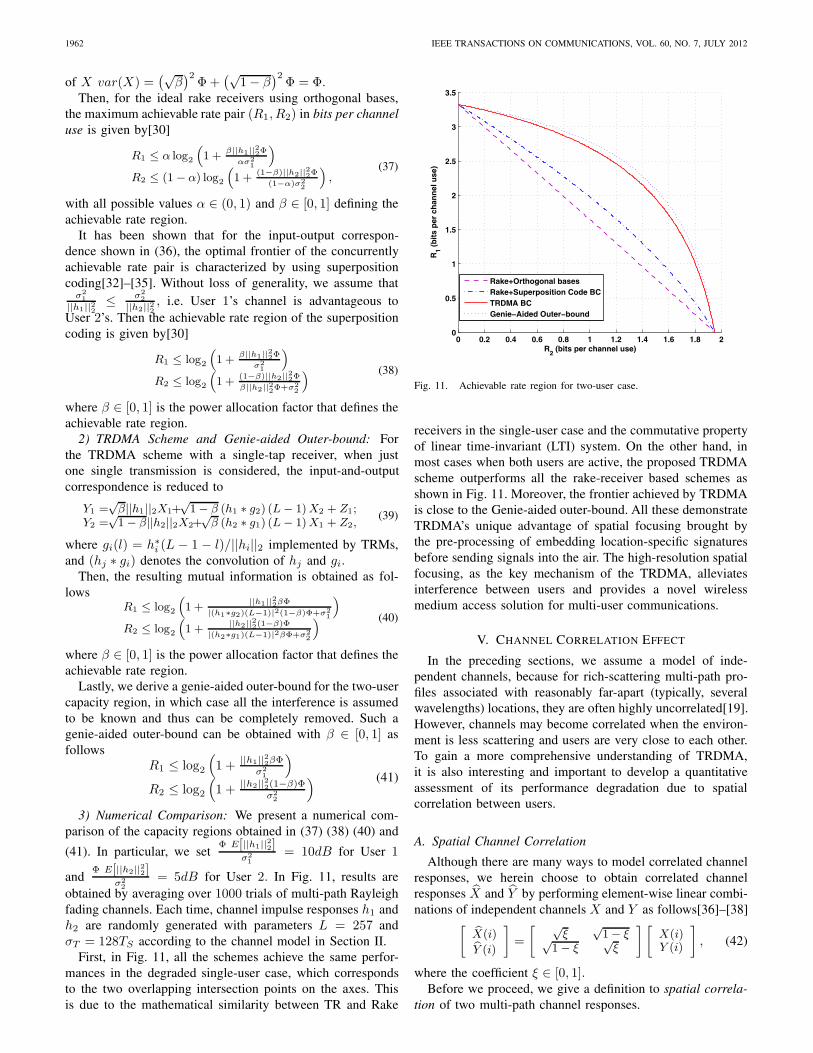
3) Numerical Comparison: We present a numerical com-parison of the capacity regions obtained in (37) (38) (40) and
(41). In particular, we setΦ E[||h1||22]
σ21
= 10dB for User 1
andΦ E[||h2||22]
σ22
= 5dB for User 2. In Fig. 11, results areobtained by averaging over 1000 trials of multi-path Rayleighfading channels. Each time, channel impulse responses h1 andh2 are randomly generated with parameters L = 257 andσT = 128TS according to the channel model in Section II.
First, in Fig. 11, all the schemes achieve the same perfor-mances in the degraded single-user case, which correspondsto the two overlapping intersection points on the axes. Thisis due to the mathematical similarity between TR and Rake
Fig. 11. Achievable rate region for two-user case.
receivers in the single-user case and the commutative propertyof linear time-invariant (LTI) system. On the other hand, inmost cases when both users are active, the proposed TRDMAscheme outperforms all the rake-receiver based schemes asshown in Fig. 11. Moreover, the frontier achieved by TRDMAis close to the Genie-aided outer-bound. All these demonstrateTRDMA’s unique advantage of spatial focusing brought bythe pre-processing of embedding location-specific signaturesbefore sending signals into the air. The high-resolution spatialfocusing, as the key mechanism of the TRDMA, alleviatesinterference between users and provides a novel wirelessmedium access solution for multi-user communications.
V. CHANNEL CORRELATION EFFECT
In the preceding sections, we assume a model of inde-pendent channels, because for rich-scattering multi-path pro-files associated with reasonably far-apart (typically, severalwavelengths) locations, they are often highly uncorrelated[19].However, channels may become correlated when the environ-ment is less scattering and users are very close to each other.To gain a more comprehensive understanding of TRDMA,it is also interesting and important to develop a quantitativeassessment of its performance degradation due to spatialcorrelation between users.
A. Spatial Channel Correlation
Although there are many ways to model correlated channelresponses, we herein choose to obtain correlated channelresponses X and Y by performing element-wise linear combi-nations of independent channels X and Y as follows[36]–[38][
X(i)
Y (i)
]=
[ √ξ
√1− ξ√
1− ξ√ξ
] [X(i)Y (i)
], (42)
where the coefficient ξ ∈ [0, 1].Before we proceed, we give a definition to spatial correla-
tion of two multi-path channel responses.
HAN et al.: TIME-REVERSAL DIVISION MULTIPLE ACCESS OVER MULTI-PATH CHANNELS 1963
E[PIUI(i)
]=[ξ2 + (1− ξ)2
]E [PIUI(i)] + 2ξ(1− ξ)
(E [PSig(i)] + E [PISI(i)] + θE
[L−1∑l=0
|hi[l]|2])
= E [PIUI(i)] +S2h1h2
2
(E [PSig(i)] + E [PISI(i)]− E [PIUI(i)] + θE
[L−1∑l=0
|hi[l]|2])
, (46)
Definition 3. For two multi-path channel responses X andY , the spatial correlation of X and Y is defined as
SXY =
L−1∑i=0
∣∣∣E [X(i)Y (i)∗
]∣∣∣√L−1∑i=0
E[|X(i)|2
]·L−1∑j=0
E[|Y (j)|2
] . (43)
Note that this definition assumes zero-mean channel re-sponses without loss of generality, and SXY takes valuesbetween 0 and 1. Particularly, when X and Y are identicalor additive inverse to each other, SXY = 1; when X and Yare uncorrelated, SXY = 0.
B. Channel correlation among users
For simplicity, we look at a two-user SISO case withcorrelated channel responses. We observe the impact of users’spatial correlation to the system performances.
Let us consider two correlated CIRs h1 and h2 obtainedfrom the linear combination of two independent CIRs h1 andh2, as shown in (42), where hi[k]’s are assumed as in SectionII to be independent circular symmetric complex Gaussianrandom variables with zero mean and variance E[|hi[k]|2] =e− kTS
σT , for 0 ≤ k ≤ L− 1.Then, the spatial correlation defined in (43) for h1 and h2
can be calculated by the simple form
Sh1h2= 2
√ξ(1− ξ). (44)
Since the spatial correlation only affects the inter-userinterference power, here we focus on the change of the averagepower of IUI as a result of channel correlations. Similar to(18), the expected value of the new IUI power PIUI(i) at Useri in such a two-user SISO case (i.e. N = 2 and MT = 1) withthe correlated CIRs h1 and h2 can be written as
E[PIUI(i)
]= θE
⎡⎣ 2L−2D∑
l=0
∣∣∣(hi ∗ gj)[Dl]
∣∣∣2⎤⎦ , (45)
where j �= i (i, j ∈ {1, 2}), and the TRM
gj [k] = h∗j [L− 1− k]
/√√√√E
[L−1∑l=0
∣∣∣hj[l]∣∣∣2]
corresponds to User j with the CIR hj .A direct calculation of (45) can be tedious. However, by
substituting uncorrelated h1 and h2 into (45) according to thelinear transform (42), we can utilize the existing results inSection III and represent the expected value of PIUI(i) interms of E [PSig(i)] , E [PISI(i)] , and E [PIUI(i)] in (20-22)
0 0.1 0.2 0.3 0.4 0.5 0.6 0.7 0.8 0.9 1−6
−4
−2
0
2
4
6
8
Spatial Correlation Sh1 h2
SIR
(dB
)
D=1D=2D=4D=8
Fig. 12. SIR vs spatial correlation with N = 2 and MT = 1.
calculated with respect to uncorrelated h1 and h2, as presentedin (46).
Note that in (46), the second term(E [PSig(i)]+E [PISI(i)]−E [PIUI(i)]+θE
[L−1∑l=0
|hi[l]|2])
is always positive, which is a penalty to the systemperformance due to the two users’ spatial correlation. WhenSh1h2
= 0 (i.e. ξ = 0 or ξ = 1), h1 and h2 are uncorrelated,
and thus E[PIUI(i)
]= E [PIUI(i)] . In the extreme case
when Sh1h2= 1 (i.e. ξ = 0.5) that maximizes (46), h1 and
h2 are identical, the IUI achieves its upper-bound
E[PIUI(i)
]=
E [PSig(i) + PISI(i) + PIUI(i)]+θE
[L−1∑l=0
|hi[l]|2]
2.
(47)
Since E [PSig(i)+PISI(i)] =E [PIUI(i)]+θE
[L−1∑l=0
|hi[l]|2]
at D = 1, (47) can be written as E[PIUI(i)
]= E [PSig(i)]+
E [PISI(i)] , when there is no rate back-off.The impact of the increased interference would be most
prominent in the high SNR regime, where the interferencepower dominates the noise power. So we evaluate its impactto the system performance in terms of signal-to-interferenceratio (SIR), as a close approximation of the effective SINR inhigh SNR regime. Fig. 12 shows the influence of the spatialcorrelation to the SIR with correlated CIRs h1 and h2 of lengthL = 257 and delay spread σT = 128TS. As one can see in
1964 IEEE TRANSACTIONS ON COMMUNICATIONS, VOL. 60, NO. 7, JULY 2012
Fig. 12, the SIR degradation speed varies with different rangesof Sh1h2
. In the lower range of Sh1h2(e.g. from 0 to 0.2)
the SIR degrades very slowly. Also, the larger rate back-offD tends to result in a faster performance loss due to spatialcorrelation as shown in Fig. 12. However, even for Sh1h2
up to 0.5 which is rare in real-life RF communications overscattering environments, the degraded SIR is preserved within3dB away from the performances of uncorrelated channels.This demonstrates the robustness of the proposed TRDMAscheme and provides a more comprehensive understanding ofits system performances.
VI. CONCLUSION
In this paper, we proposed a TRDMA scheme for themulti-user downlink network over multi-path channels. Bothsingle-antenna and multi-antenna schemes were developed toutilize the location-specific signatures that naturally exist inthe multi-path environment. We defined and evaluated bothanalytically and numerically a variety of performance metricsof including the effective SINR, the achievable sum rate,and achievable rates with outage. We then demonstrated theTRDMA’s improvement of achievable rate region over the rakereceivers and investigated the impact of spatial correlationsbetween users to the system performances. Based on the niceproperties shown in the analysis and simulation results of thispaper, the proposed TRDMA can be a promising technique inthe future energy-efficient low-complexity broadband wirelesscommunications.
REFERENCES
[1] J. G. Proakis, Digital Communications, 4th edition. McGraw-Hill, 2001.[2] G. L. Stuber, Principles of Mobile Communications, 2nd edition.
Kluwer, 2001.[3] A. J. Goldsmith, Wireless Communication. Cambridge University Press,
2005.[4] D. Tse and P. Viswanath, Fundamental of Wireless Communication.
Cambridge University Press, 2005.[5] B. Wang, Y. Wu, F. Han, Y. H. Yang, and K. J. R. Liu, “Green
wireless communications: a time-reversal paradigm,” IEEE J. Sel. AreasCommun., vol. 29, no. 8, pp. 1698–1710, Sep. 2011.
[6] M. Fink, C. Prada, F. Wu, and D. Cassereau, “Self focusing in inho-mogeneous media with time reversal acoustic mirrors,” in Proc. 1989IEEE Ultrasonics Symp., vol. 1, pp. 681–686.
[7] C. Prada, F. Wu, and M. Fink, “The iterative time reversal mirror: asolution to self-focusing in the pulse echo mode,” J. Acoustic SocietyAmerica, vol. 90, pp. 1119–1129, 1991.
[8] M. Fink, “Time reversal of ultrasonic fields—part I: basic principles,”IEEE Trans. Ultrasonic, Ferroelectron., Frequency Control, vol. 39,pp. 555–566, Sep. 1992.
[9] C. Dorme and M. Fink, “Focusing in transmit-receive mode throughinhomogeneous media: the time reversal matched filter approach,” J.Acoustic Society America, vol. 98, no. 2, part 1, pp. 1155–1162, Aug.1995.
[10] A. Derode, P. Roux, and M. Fink, “Robust acoustic time reversal withhigh-order multiple scattering,” Phys. Rev. Lett., vol. 75, pp. 4206–4209,1995.
[11] W. A. Kuperman, W. S. Hodgkiss, and H. C. Song, “Phase conjugationin the ocean: experimental demonstration of an acoustic time-reversalmirror,” J. Acoustic Society America, vol. 103, no. 1, pp. 25–40, Jan.1998.
[12] H. C. Song, W. A. Kuperman, W. S. Hodgkiss, T. Akal, and C. Ferla,“Iterative time reversal in the ocean,” J. Acoustic Society America,vol. 105, no. 6, pp. 3176–3184, June 1999.
[13] D. Rouseff, D. R. Jackson, W. L. Fox, C. D. Jones, J. A. Ritcey, andD. R. Dowling, “Underwater acoustic communication by passive-phaseconjugation: theory and experimental results,” IEEE J. Oceanic Eng.,vol. 26, pp. 821–831, 2001.
[14] A. Derode, A. Tourin, J. de Rosny, M. Tanter, S. Yon, and M. Fink“Taking advantage of multiple scattering to communicate with time-reversal antennas,” Phys. Rev. Lett., vol. 90, pp. 014301-1–014301-4,2003.
[15] D. Rouseff, D. R. Jackson, W. L. J. Fox, C. D. Jones, J. A. Ritcey, andD.R. Dowling, “Underwater acoustic communication by passive-phaseconjugation: theory and experimental results,” IEEE J. Oceanic Eng.,vol. 26, pp. 821–831, 2001.
[16] G. F. Edelmann, T. Akal, W. S. Hodgkiss, S. Kim, W. A. Kuperman,and H. C. Song, “An initial demonstration of underwater acousticcommunication using time reversal,” IEEE J. Oceanic Eng., vol. 27,pp.602–609, 2002.
[17] S. M. Emami, J. Hansen, A. D. Kim, G. Papanicolaou, and A. J. Paulraj,“Predicted time reversal performance in wireless communications,”IEEE Commun. Lett., 2004.
[18] M. Emami, M. Vu, J. Hansen, A. J. Paulraj, and G. Papanicolaou,“Matched filtering with rate back-off for low complexity communi-cations in very large delay spread channels,” in Proc. Asilomar Conf.Signals, Syst. Comput., vol. 1, pp. 218–222.
[19] K. F. Sander and G. A. L. Reed, Transmission and Propagation ofElectromagnetic Waves, 2nd edition. Cambridge University Press, 1986.
[20] H. T. Nguyen, I. Z. Kovacs, and P. C. F. Eggers, “A time reversaltransmission approach for multiuser UWB communications,” IEEETrans. Antennas Propag., vol. 54, no. 11, pp. 3216–3224, Nov. 2006.
[21] I. H. Naqvi, A. Khaleghi, and G. E. Zein, “Performance en-hancement of multiuser time reversal UWB communication sys-tem,” 2007 IEEE International Symp. Wireless Commun. Syst.[http://arXiv:0810.1506v1[cs.NI]].
[22] H. T. Nguyen, “Partial one bit time reversal for UWB impulse radiomulti-user communications,” in Proc. 2008 International Conf. Com-mun. Electron., pp. 246–251.
[23] H. Nguyen, Z. Zhao, F. Zheng, and T. Kaiser, “Pre-equalizer design forspatial multiplexing SIMO UWB systems,” IEEE Trans. Veh. Technol.,vol. 59, no. 8, pp. 3798–3805, Oct. 2010.
[24] T. K. Nguyen, H. Nguyen, F. Zheng, and T. Kaiser, “Spatial correlationin SM-MIMO-UWB systems using a pre-equalizer and pre-rake filter,”2010 IEEE International Conf. Ultra-Wideband.
[25] T. K. Nguyen, H. Nguyen, F. Zheng, and T. Kaiser, “Spatial correlationin the broadcast MU-MIMO UWB system using a pre-equalizer and timereversal pre-filter,” 2010 International Conf. Signal Process. Commun.Syst.
[26] A. Derode, A. Tourin, and M. Fink, “Ultrasonic pulse compression withone-bit time reversal through multiple scattering,” J. Applied Physics,vol. 85, no. 9, May 1999.
[27] H. V. Poor and G. W Wornell, Wireless Communications: SignalProcessing Perspectives, 1st edition. Prentice Hall, 1998.
[28] P. H. Moose, “A technique for orthogonal frequency division multiplex-ing frequency offset correction,” IEEE Trans. Commun., vol. 42, no. 10,pp. 2908–2914, Oct. 1994.
[29] J. Lee, H.-ling Lou, D. Toumpakaris, and J. M. Cioffi, “SNR analysisof OFDM systems in the presence of carrier frequency offset for fadingchannels,” IEEE Trans. Wireless Commun., vol. 5, no. 12, pp. 3360–3364, Dec. 2006
[30] T. M. Cover and J. A. Thomas, Elements of Information Theory. JohnWiley & Sons, 2006.
[31] J. L. Massey, “Towards an information theory of spread-spectrum sys-tems,” in Code Division Multiple Access Communications, S. G. Glisicand P. A. Leppanen, editors, pp. 29–46. Kluwer Academic Publishers,1995.
[33] P. P. Bergmans, “Random coding theorem for broadcast channels withdegraded components,” IEEE Trans. Inf. Theory, vol. IT-19, no. 1pp. 197–207, Mar. 1973.
[34] P. P. Bergmans, “A simple converse for broadcast channels with additivewhite Gaussian noise,” IEEE Trans. Inf. Theory, vol. IT-20, no. 2pp. 279–280, Mar. 1974.
[35] P. P. Bergmans and T. M. Cover, “Cooperative broadcasting,” IEEETrans. Inf. Theory, vol. IT-20, no. 3 pp. 317–324, Mar. 1974.
[36] A. Papoulis and U. Pillai, Probability, Random Variables and StochasticProcesses, 4th edition. McGraw-Hill, 2002.
[37] R. B. Ertel and J. H. Reed, “Generation of two equal power correlatedRayleigh fading envelopes,” IEEE Commun. Lett., vol. 2, no. 10. Oct.1998.
[38] B. Natarajan, C. R. Nassar, and V. Chandrasekhar, “Generation ofcorrelated Rayleigh fading envelopes for spread spectrum applications,”IEEE Commun. Lett., vol. 4, no. 1. Jan. 2000.
HAN et al.: TIME-REVERSAL DIVISION MULTIPLE ACCESS OVER MULTI-PATH CHANNELS 1965
Feng Han (S’08) received the B.S. and M.S. degreesin Electronic Engineering from Tsinghua University,Beijing, China, in 2007 and 2009, respectively. Heis currently pursuing the Ph. D. degree in ElectricalEngineering, at the University of Maryland, CollegePark. His current research interests include wirelesscommunications and networking, smart grid, gametheory, and information theory.
He is a recipient of the first prize in the 19thChinese Mathematical Olympiad, the Best ThesisAward of Tsinghua University, the honor of Ex-
cellent Graduate of Tsinghua University, the A. James Clark School ofEngineering Distinguished Graduate Fellowship in 2009 and the FutureFaculty Fellowship in 2012, both from the University of Maryland, CollegePark. He received a Best Paper Award for his work on MIMO system at IEEEWCNC’08, Las Vegas, NV, in 2008.
Yu-Han Yang (S’06) received his B.S. in electri-cal engineering in 2004, and two M.S. degrees incomputer science and communication engineeringin 2007, from National Taiwan University, Taipei,Taiwan. He is currently pursuing the Ph.D. degreeat the University of Maryland, College Park. Hisresearch interests include wireless communicationand signal processing. He received Class A Scholar-ship from National Taiwan University in Fall 2005and Spring 2006. He is a recipient of Study AbroadScholarship from Taiwan (R.O.C.) Government in
2009 and 2010.
Beibei Wang (S’07-M’11) received the B.S. degreein electrical engineering (with the highest honor)from the University of Science and Technology ofChina, Hefei, in 2004, and the Ph.D. degree inelectrical engineering from the University of Mary-land, College Park in 2009. From 2009 to 2010,she was a research associate at the University ofMaryland. Currently, she is a senior engineer withCorporate Research and Development, QualcommIncorporated, San Diego, CA.
Her research interests include wireless communi-cations and networking, including cognitive radios, dynamic spectrum allo-cation and management, network security, and heterogeneous networks. Dr.Wang was the recipient of the Graduate School Fellowship, the Future FacultyFellowship, and the Dean’s Doctoral Research Award from the University ofMaryland, College Park. She is a coauthor of Cognitive Radio Networkingand Security: A Game-Theoretic View, Cambridge University Press, 2010.
Yongle Wu (S’08-M’12) received the Ph.D. de-gree in Electrical and Computer Engineering fromUniversity of Maryland, College Park in 2010. Hereceived the B.S. (with highest honor) and M.S.degrees in Electronic Engineering from TsinghuaUniversity, Beijing, China, in 2003 and 2006, re-spectively.
Dr. Wu is currently a senior engineer with Qual-comm Incorporated, San Diego, CA. His researchinterests are in the areas of wireless communicationsand networks, including cognitive radio techniques,
dynamic spectrum access, network security, and MIMO-OFDM communica-tion systems.
Dr. Wu received the Graduate School Fellowship from the University ofMaryland in 2006, the Future Faculty Fellowship in 2009 and the Litton In-dustries Fellowship in 2010, both from A. James Clark School of Engineering,University of Maryland, and the Distinguished Dissertation Fellowship fromDepartment of Electrical and Computer Engineering, University of Marylandin 2011.
K. J. Ray Liu (F’03) is named a DistinguishedScholar-Teacher of University of Maryland, Col-lege Park, in 2007, where he is Christine KimEminent Professor of Information Technology. Heserves as Associate Chair and Director of GraduateStudies and Research of Electrical and ComputerEngineering Department and leads the MarylandSignals and Information Group conducting researchencompassing broad areas of signal processing andcommunications with recent focus on cooperativecommunications, cognitive networking, social learn-
ing and networks, and information forensics and security.Dr. Liu is the recipient of numerous honors and awards including IEEE
Signal Processing Society Technical Achievement Award and DistinguishedLecturer. He also received various teaching and research recognitions fromUniversity of Maryland including university-level Invention of the YearAward; and Poole and Kent Senior Faculty Teaching Award and OutstandingFaculty Research Award, both from A. James Clark School of Engineering.An ISI Highly Cited Author in Computer Science, Dr. Liu is a Fellow ofIEEE and AAAS.
Dr. Liu is President of IEEE Signal Processing Society where he has servedas Vice President - Publications and Board of Governor. He was the Editor-in-Chief of IEEE Signal Processing Magazine and the founding Editor-in-Chiefof EURASIP Journal on Advances in Signal Processing.