This article has been accepted for inclusion in a future issue of this journal. Content is final as presented, with the exception of pagination.
IEEE TRANSACTIONS ON CONTROL SYSTEMS TECHNOLOGY 1
Accurate Bolt Tightening Using Model-Free FuzzyControl for Wind Turbine Hub Bearing Assembly
Christian Deters, Hak-Keung Lam, Senior Member, IEEE, Emanuele Lindo Secco, Helge A. Würdemann,Lakmal D. Seneviratne, Member, IEEE, and Kaspar Althoefer, Member, IEEE
Abstract— In the modern wind turbine industry, one of thecore processes is the assembly of the bolt-nut connections of thehub, which requires tightening bolts and nuts to obtain well-distributed clamping force all over the hub. This force deals withnonlinear uncertainties due to the mechanical properties and itdepends on the final torque and relative angular position of thebolt/nut connection. This paper handles the control problem ofautomated bolt tightening processes. To develop a controller, theprocess is divided into four stages, according to the mechanicalcharacteristics of the bolt/nut connection: a fuzzy logic controller(FLC) with expert knowledge of tightening process and errordetection capability is proposed. For each one of the four stages,an individual FLC is designed to address the highly nonlinearityof the system and the error scenarios related to that stage, topromptly prevent and avoid mechanical damage. The FLC isimplemented and real time executed on an industrial PC andfinally validated. Experimental results show the performance ofthe controller to reach precise torque and angle levels as well asdesired clamping force. The capability of error detection is alsovalidated.
W IND turbine industry is one of the most promisingtechnologies within renewable energies field, compared
with other ones like solar energy. Power generation throughwind has reached a mature technology level, good infrastruc-ture, and convinces with regards to cost competitiveness [1];wind energy is likely to play an essential role in the futurefor replacing a number of currently used energy sources [2].Predictions outline that wind energy may supply 12% ofthe overall world’s demand in the near future, meaning thatturbines will be more powerful and wind parks are likely tosee turbines with increased rotor diameters [3], [4].
Research into wind turbine manufacturing is an importanttopic with a number of challenges and potentially far-reachingramifications in a fast-developing market. One critical processof wind turbine manufacturing is the hub assembly process [5].Essential to hub assembly is successfully creating accurate
Manuscript received January 13, 2014; accepted February 13, 2014.Manuscript received in final form March 3, 2014. This work was sup-ported by the European Community, Seventh Framework Programmeunder Grant FP7-NMP-2009-SMALL-3 and Grant NMP-2009-3.2-2 throughthe EU Project COSMOS under Grant 246371-2. Recommended by AssociateEditor H. Gao.
Digital Object Identifier 10.1109/TCST.2014.2309854
Fig. 1. Overall assembly process (picture provided by Gamesa Corp.).
bolt-nut connections between the blades bearings and the mainhub component (Fig. 1); hub assembly is currently performedmanually by workers employing torque wrenches, hydraulictensioning tools and gauges [6]. The assembly process requiresto be completed with high precision, according to strictspecifications—bolts improperly tightened to a faulty level orthose suffering from mechanical damage are to be avoidedand such failure scenarios are to be detected early on in theassembly process.
Although hub assembly is usually conducted by humanworkers, some research on automating the bolt-tighteningprocess has been conducted. Current control strategies onbolt tightening are based on the concept of proportional-integral-derivative (PID) control, and, in some cases, com-bined with torque/angle tightening technique [7]. In general,PID controllers are well accepted within industrial applicationsand exhibit high performance on linear systems. However,the tightening process exhibits nonlinearities and uncertain-ties due to mechanical friction between the bolt and nutthreads, variations of environmental temperature, presence ofphysical damages on threads [8]–[13]. Therefore, a simplePID controller with fixed values of proportional, integral, andderivative gains may not provide sufficient level of tighteningperformance [14].
This motivates the use of alternative techniques like model-free fuzzy logic controllers (FLCs), which demonstrate abetter capability to deal with uncertainties and nonlinearities[15]–[24]. Model-free FLCs allow employing expert knowl-edge on tightening and even detection of failure scenarios suchas cross treading, screw jamming, slippage, and misalignmentsduring the tightening process [7], [18], [25]–[30]. It is notedthat in a model-based approach, problems like variation offriction, material properties variation, bolt size, and installationalterations would require different models for each case, which
This article has been accepted for inclusion in a future issue of this journal. Content is final as presented, with the exception of pagination.
2 IEEE TRANSACTIONS ON CONTROL SYSTEMS TECHNOLOGY
cannot be easily and precisely included within a numericalmodel.
A theoretical FLC concept addressing all nonlinear com-ponents of screw fastening has been presented in [19]. How-ever, this latter paper is not using the introduced four-stagetightening strategy—as indeed has been proposed in [31]—toaddress the specific nonlinear components of the bolt system.On the contrary, these ones can be controlled by the introducedmodel-free approach; in addition, an approach like the onereported in [19], does not provide error recognition andtargets industrial integration. Moreover, the tightening toolruns on different rotational speeds to avoid damages in criticalphases of the process. It is noted that the approach proposedhere includes error detection—an idea that was also exploredby others with regards to a range of dynamically operatedsystems, including motor control, wind energy conversion,winch drive, and screw fastening [16], [25], [30], [32], [33],allowing early detection of common error scenarios based ontorque/angle tightening information [7], [34].
This paper investigates bolt-tightening based on a practicalmanufacturing situation. In view of the complexity of thesystem and control process, a model-free Mamdani-type FLC[26]–[28], [35], [36], which allows the integration of expertknowledge with the control methodology, is employed to serveas a controller for the control of: 1) the output torque and2) the angle of the bolt-tightening tool. To facilitate the designof the FLC, the process is divided into four stages accordingto mechanical properties, such as thread size and type, boltmaterial, and washer size [37]. Knowledge on each stage isemployed to establish a rule base and membership functionsfor the FLC. As an individual fuzzy controller is designed foreach stage, nonlinearity can be clearly addressed and utilizedfor control design to improve the performance of the overallsystem [29], [35], [38]–[40]. To realize the fuzzy error detectorfor each stage, knowledge on potential error scenarios such asmisalignment of the nut on the bolt, mechanical damages ofthe bolt or the nut, incorrect thread types and sizes are definedin linguistic rules based on Mamdani FLC. Since differentwind turbine hubs define different tightening specifications, theparameters within the FLC can be changed according to theassembly specifications to achieve the specified torque/angle.The proposed FLC, error detector, and status determiner areimplemented on a real-time industrial control system. Experi-ments are conducted to show the merits of the proposed controlscheme.
This paper is organized as follows. Section II shows thenut assembly process, which are divided into four stagessupporting the design of the FLC and error detector. SectionIII introduces the tightening stages and the FLC. Section IVpresents the experimental results. The conclusion is drawn inSection V.
II. MATERIALS AND METHODS
A. Wind Turbine Assembly and Bolt Tightening
The wind turbine hub is made of three main parts, whichare the hub, the bearing, and the pitch system. The bearingsare assembled using up to 128 bolts (depending on the windturbine hub) to connect them to the hub (Fig. 1).
Fig. 2. Four stages of the bolt tightening process [17], [18].
Fig. 3. Alignment problems.
B. Sequence of Bolt Tightening
The sequence for bolt tightening is essential for accuratetightening as well as for assembly error detection. The processhas been analyzed and it can be subdivided into four differentstages. Stage 1 regards the initial bolt/nut alignment. This willsubsequently lead to partial and full engagement (Stages 2and 3, respectively) of the bolt and the nut; finally, as soon asthe nut will touch the flange, the system starts Stage 4, whichis the final part of the tightening process.
1) Stage 1—Bolt/Nut Alignment: At the beginning of thetightening process, the female and male threads of the boltand the nut meet at their starting point (Fig. 2, top left panel).In this stage, the requirement for the controller is to providea slow start to avoid possible damages to the threads of thebolt and nut in case a jamming situation arises and to applythe required torque levels within a specific low range of theirrelative angular position. Since the bolt has a round shape,misalignment situations may arise and cause damage (Fig. 3),therefore, in such a situation, the assembly should be promptlystopped and the bolt replaced. This also may happen in anothererror scenarios such as if a wrong bolt is used, e.g., with athread type different from that of the nut. Therefore, the aimof this stage is to move the nut into a specified angle and toassure a proper alignment between the nut and bolt avoidingall of the aforementioned errors.
2) Stage 2—Partial Engagement: The nut is tightened fora few degrees ensuring that both bolt and nut threads aretouching each other (Fig. 2, top right panel). This matchrequires a small value of applied torque to overcome thefriction caused by the two threads being in contact. Possibleerror scenarios of this stage include three types of cross
This article has been accepted for inclusion in a future issue of this journal. Content is final as presented, with the exception of pagination.
DETERS et al.: ACCURATE BOLT TIGHTENING USING MODEL-FREE FUZZY CONTROL 3
threads: 1) in the nut; 2) in the top region of the bolt; and3) due to different thread types. In this case, continuing thetightening may lead to a jamming situation, and, in turn, maycause to an unexpected and unwanted higher torque level.
Another possible error is due to bolt/nut misalignment: inFig. 3, the tilt angle � refers to misplacement originating,for example, from a wrong automatic pick and place process.Angle � should be zero, otherwise the nut may get jammed. Itis noted that tightening angle γ describes the tightening anglerange and depends on the assembly specification.
3) Stage 3—Full Engagement: At this stage, the nut isrunning down until reaching the flange and a maximum andsteady friction level occurs (Fig. 2, bottom left panel). Possibleerrors include cross threads on the bolts shaft and dirt betweenthe threads, which can be detected by unexpectedly high torque(HT). Monitoring the angular displacement of the nut is veryimportant in this phase, since it contains feedback about howfar the nut has been traveled along the bolt shaft. Moreover,this information aids the estimation of the effective bolt length(as detailed in the assembly specifications) and—based onthe travelled distance of the nut—the detection of wrong ormissing washers.
4) Stage 4—Final Bolt Tightening: The final part of thetightening process starts as soon as the nut has reached theflange. Turning the nut during this part of the tighteningprocess generates the desired clamping force between theflange and the nut (Fig. 2, bottom right panel). The torquelevel as well as the final angular position of the nut areprovided within the assembly specifications. Accordingly, therequirement of this stage is to apply appropriate values oftorque within well-defined angular displacements and withoutexceeding the bolt tension limit (TL), since otherwise errorswould occur.
C. Control Architecture
A Mamdani FLC was setup, incorporating expert knowledgeresulting in a set of rules, the four-stage bolt-nut tighteningprocess was created. According to [35], the overall controllerstructure is
MAMD(x, y) =n∨
i=1
(Ai (x) and Bi (y) (1)
where Ai and Bi are the fuzzy numbers [e.g., low angle (AL)and desired angles] as a listening of n-possibilities. In (1), thefuzzy numbers can be seen as x is A1 and y is B1 or x isA2 and y is B2, and so on. Fuzzy rules can be integrated asconjunction of implications
RULES(x, y)=n∧
i=1
(Ai (x)→Bi (y). (2)
In (2), the rules have been set as a listening of n possibilities:if x is A1 then y is B1 and x is A2 then y is B2.
The FLC inputs and outputs are tightening tool angularposition (measured by means of an integrated encoder) andtorque (measured using integrated strain gauge sensor), respec-tively (Fig. 4). A further input, error signal is used for TLdetection, which monitors the velocity of the torque (if it
Fig. 4. Generic control diagram used for all Stages 1–4.
Fig. 5. Overall controller architecture.
becomes constant the plastic region is reached). The output is avoltage signal in the ±10 V range, which sets the tool spinningspeed; an additional tension limit input is introduced, whichis linked to the torque velocity (if the velocity is constantand the angle increases, the plastic region of the bolt has beenreached). The control error, namely the difference between thereal torque/angle and their desired values, is minimized usingthe membership functions—which define the targeted controlvalues and error values, and the linguistic rules—within theFLC block. Therefore, no additional error feedback is shownwithin the controller scheme (Fig. 4) and the torque/anglevalues are directly fed into the controller.
Since this application is to be used within an indus-trial environment, the architecture use a programmablelogic controller (PLC) system [41], which integrates MAT-LAB/Simulink programming language (Mathworks Inc.)within a real-time Beckhoff TwinCAT 3 software automationsystem [42]. In our setup, the PLC is connected to an IndustrialFanuc M6iB Robot arm, which is equipped with a DSMBL 57/140 MDW tightening tool attached to the end-effectorflange (Fig. 5). A bolt bench with three bolts is used tosimulate the bolt tightening process (Fig. 5).
The FLC is cyclically executed to exchange data with thePLC, which is connected with the tool. Control signals aresent back to the PLC in real-time; we note two importantadvantages:
1) different FLCs can be selected by the same PLC, accord-ing to different bolt types;
2) multiple tools can be integrated by calling the FLCseveral times.
This article has been accepted for inclusion in a future issue of this journal. Content is final as presented, with the exception of pagination.
4 IEEE TRANSACTIONS ON CONTROL SYSTEMS TECHNOLOGY
Fig. 6. Membership functions of Stage 1.
TABLE I
LINGUISTIC RULES FOR STAGE 1
1) Stage 1 Control Strategy (Bolt/Nut Alignment): Anmultiple-input, multiple-output FLC with two inputs, torqueand angle as sensing inputs, and two outputs, voltage forsetting the tool’s speed and an signal for reporting an errorscenario, has been designed. To define the angle and torquelevels, an experiment has been carried out to estimate thevalues for a normal completion of Stage 1. It turned out thatthe nut is aligned after c. 7° at a torque level of c. 5 Nm.If a misalignment occurs, the angle level cannot be reachedby applying the normal torque (NT), as the nut is jammed.Based on these experimental verified levels, the membershipfunctions defined in Stage 1 defined.
In Stage 1, the input torque of the FLC contains threeGaussian membership functions named “low torque (LT)”,“normal torque (NT)” and “high torque (HT)”; the input anglecontains two membership functions, which are called ”lowangle (AL)” and “desired angle (AD)”; the output voltagecontains three membership functions, namely “negative volt-age (VN)”, “zero voltage (VZ)” and “positive voltage (VP)”.All membership functions are in the Gaussian shape, as shownin Fig. 6.
The fuzzy rule set is reported in Table I, where the fourthcolumn refers to the output of the fuzzy error detector, whichgenerates either a true (T) status, indicating an erroneouscondition, or a false (F) status, indicating proper operation.In the first case, the FLC switches off the output voltage andreports an error output by sending a supervisory signal tothe PLC. During operation, the tightening tool rotates until itreaches the starting position (where the bolt and the nut threadmeet); then the torque slightly increases and the control targetof Stage 1 is satisfied.
2) Stage 2 Control Strategy (Partial Engagement): Stage 2FLC has a structure similar to the previous one, with themembership functions of the angle adapted to the desiredangular range (Fig. 7), such that if a high torque scenario
Fig. 7. Membership functions of Stage 2.
Fig. 8. Membership functions of Stage 3.
arises, the voltage output is set to zero and an error outputis returned. The membership functions are linked using thesame linguistic rules as reported in Table I and the sectiondescribing Stage 1. Stage 2 is entirely angle-based, since onlythree to five entire turns of the nut are required for this stageto complete.
It is noted that the angle levels of the membership functionsfor Stage 2 are 10 times higher. This level has also beenestimated experimentally to ensure the nut is in the desiredposition to continue to Stage 3. The torque level stays thesame, as only in an error scenario the torque will go up—it isonly monitored to detect error scenarios.
3) Stage 3 Control Strategy (Full Engagement): In Stage 3,the FLC contains also two inputs (torque and angle forsensing) as well as two outputs (the voltage and error signal foractuation), as in the previous stages. Compared with Stage 1,the angle range has to be redefined to cover the expected rundown angle range of the bolt’s shaft down to the washer/flange;moreover the error detector has to identify any possible hightorque scenarios, which may be caused by cross threads onthe shaft (caused by a low angle and a high torque scenario).Accordingly, the membership functions have been specified,as shown in Fig. 8.
Due to the presence of friction between the bolt and the nut,the baseline of the torque value within the fuzzy rules have tobe increased (as the nut’s thread is now fully set on the bolt’sthread) and furthermore the angle region has to be redefined toestimate whether a correct washer has been installed (a missingor false washer would cause a high angle scenario) and toinclude the target angle. A high torque scenario within thelow angle region would be indicative of a problem (as thesituation of a cross thread on the bolt or too short a bolt beinginstalled) and must stop the tightening action. According toall these concerns, more membership functions and linguisticrules have to be defined within this stage, as shown in Table II.
Stage 3 is also entirely angle based, as the control target isto run the nut down to the washer/flange. The angle has beenestimated based on experimental results and may be modifiedfor different bolt sizes. The torque level is increased as thenut is now completely on the bolts thread, which increases
This article has been accepted for inclusion in a future issue of this journal. Content is final as presented, with the exception of pagination.
DETERS et al.: ACCURATE BOLT TIGHTENING USING MODEL-FREE FUZZY CONTROL 5
TABLE II
LINGUISTIC RULES FOR STAGES 2 AND 3
the friction. Experiments showed that the applied torque isaround 7-Nm maximum.
4) Stage 4 Control Strategy (Tightening Process): TheFLC in Stage 4 tightens the nut to the final desired torqueand within a specified and desired angular range. Here,the TL has to be preserved (meaning that the bolt cannotbe over tightened, possibly due to a wrong bolt installa-tion). Therefore, the controller is setup using three sensinginputs (torque, tension-limit, and angle) and two outputs(voltage to set the tool speed and one supervisory signalfor the error and tension-limit detection). Two compara-tors have been implemented with experimentally estimatedthresholds, which are linked to the tightening and tensioninglimit output respectively, this setup enables the error andTL detection.
Three membership functions are assigned to each of theinputs. The error recognition should detect if the bolt reachesits TL due to a deviation of the torque from the allowedrange of torque levels; as soon as the torque velocity remainsconstant and the angle is still increasing, the plastic regionof the bolt has been reached and the tightening process muststop, either with an error (if the torque has not been reached)or with no error (if the torque has been reached and the angularposition is within the desired range).
Furthermore, in this stage, the FLC returns to thePLC system whether the process has been success-fully completed or not. According to these observations,the membership functions for the tension limit are imple-mented in addition to the membership functions introduced inFig. 9: reached tension limit (RT), “close tension limit (CL)”,and functions are also introduced.
The outputs of the tightening (TIGH) and of the tensionlimit (TL) are supervisory signals set by the FLC then a set of27 linguistic rules has been set up to cover the required actions(Table III) based on all possible input scenarios and outputs.The overarching system (factory control system) receives anerror signal, which is either true in an error scenario or falseif the process has been completed without errors, the currentstage is transferred as well.
Combining all membership functions and linguistic rules,the overall FLC shape is obtained, as shown in Fig. 10.
Fig. 9. Membership functions of Stage 4.
TABLE III
STAGE 4 LINGUISTIC RULES
III. VALIDATION
A. Experiment Setup
The previous section introduced a four-stage FLCperforming bolt tightening with error detection. To validate thesystem in an industrial software and hardware environment,the controller was initially implemented using the MATLAB/SIMULINK Programming Language and then imported intothe Beckhoff TwinCAT 3 system using MATLAB coder. Thecontroller is then executed at a cycle frequency of 2 kHz(i.e., with a cycle time of 500 μs). This cycle time was selecteddue to the speed requirement of the tightening process.
This article has been accepted for inclusion in a future issue of this journal. Content is final as presented, with the exception of pagination.
6 IEEE TRANSACTIONS ON CONTROL SYSTEMS TECHNOLOGY
Fig. 10. From the top left to the bottom right panel, the s Stages 1–4membership functions with their linguistic rules, respectively.
The tightening tool (model DSM BL 57—maximum torqueperformance of 140 Nm) was mounted on the end-effectorof a Fanuc M6i-B robot arm; during a regular tighteningprocedure, the robot picks an M24 nut and places it on the topof M24 bolt; the rotational tightening speed was controlled bya voltage command, whereas an optical encoder and torquesensor—both integrated within the tool-measured angle andtorque levels, respectively. The inputs to the FLC were theacquired angle and torque values, while the FLC outputs werethe voltage control signals driving the tool motor and an errorsignal, reporting on the type of experienced error scenario.
A washer sensor (MecSense KMR 50 KN), for measuringthe clamping force, was inserted between the nut and theflange to measure the effective performance of the tighteningprocess. Generally, the clamping force depends on multiplefactors like the applied torque, the relative angular positionsbetween the bolt and nut threads, the geometric and mechani-cal characteristics of their contact surfaces to name a few [18].Usually, this washer sensor is not installed in the physicalassembly line and is only used here for verification of ourapproach.
B. Validation Scenarios
Several tightening processes were performed, as well assessions for testing the error detection capabilities of ouralgorithm. In particular, to test the error detection capabilities,diverse error scenarios were set up during the tighteningprocesses. The error feedback is setup using a Boolean flagwithin the PLC, which returns the actual torque, angle andstage values as soon as an error is detected.
The performance of the FLC was also compared with theperformance of a classical industrial PID controller oftenemployed for bolt tightening.
C. Error Recognition Performance
To validate the controller and its capability to detect theerrors, six experimental sessions were performed involvingdifferent error scenarios (S). For regular tightening (S1), 30trials have been conducted to show the accuracy of the FLC
Fig. 11. Misalignment error. The robot places the nut on a faulty angle,which causes the nut to be stuck on the bolt as soon as tightening process isstarted.
and compare it with a PID controller. For the error detection(S2–S6), eight trials have been conducted on each scenario todemonstrate the error detection capabilities. At the beginningof each trial, the tightening tool loaded the nut and waspositioned in front of the bolt; then, the controller was startedand executed until completing the tightening process or anyerror detection occurred.
The desired torque level is depending on the application’sspecification. In wind turbine manufacturing, HT values areusually required during hub. Based on the specifications, thePLC sets the membership function parameters for the desiredtorque and angle and starts the controller.
Six scenarios (S1–6) (listed below) replicating typical errorsoccurring while an operator performs bolt tightening dur-ing wind turbine assembly are investigated. Furthermore,these scenarios were conceived and designedto possibly coverdiverse corresponding error detections within the four stagesof the tightening process. These are the six scenarios that wereexperimentally validated.
1) Regular Tightening (S1): No error detection wasexpected within this scenario, since a correct M24 nut waspositioned on the tightening tool and in front of an M24 bolt.
2) Misalignment Error (S2): The tool and the nut wereerroneously positioned with respect to the bolt, to replicate themisalignment error (Fig. 11); the error detection was expectedto occur at Stage 1.
3) Jamming Error (S3): A nonmetric nut was tightened onan M24 bolt; the error was expected to be detected at Stage 2,since the torque level would rise up to an undesirable levelat this stage. The threads of the nut and the bolt were alsoexpected not to grab one into the other, due to their differentgeometric shapes.
4) Insertion of Two Washers (S4): In this scenario, oneadditional washer was added on top of the original washerused (Fig. 12) and the system was expected to recognize itspresence during the Stage 3 or early Stage 4 because the torquelevel would rise to too high a value within Stage 3 and wouldstay at that overly high level at a low angle in Stage 4.
Fig. 12 shows a two washers’ scenario. In this condition, thetightening angle cannot be reached according to the assemblyspecifications; therefore, the torque level increases beforea specified angle is reached and an error is detected.
5) Missing Nut (S5): To simulate a mistake of the operator,the nut was removed from the tightening tool (Fig. 13). In thissituation, the controller error detection was foreseen to occur
This article has been accepted for inclusion in a future issue of this journal. Content is final as presented, with the exception of pagination.
DETERS et al.: ACCURATE BOLT TIGHTENING USING MODEL-FREE FUZZY CONTROL 7
Fig. 12. Two washers error scenario. The second washer will cause an errordetection within Stage 3 or 4, since the desired angular position of the nutwill not be reached.
Fig. 13. Missing nut scenario: the tool is touching the washer as soon as itis placed on the nut, because of the missing nut.
at Stage 3, because no increase in the torque was expectedand the angle is expected to increase in value without bounds,in Stage 3. As shown in the last figure, the tightening toolspins on the bolt as there is no nut, which causes an increaseof the torque value. This should cause an error since thecontroller is expecting a rise in the torque within the Stage 3,at comparatively low angular values. Finally, the nut runner istouching and spinning on the washer since there is no nut inthis particular setup.
6) Wrong Bolt Versus Nut (S6): The proper M24 nut wasreplaced with an inappropriate M14 nut too small. In thiscondition, the controller runs into Stage 3, as the torque levelremains on a low level and the wrong bolt error should finallyoccur at Stage 3. This type of error can also imply that toosmall a nut-runner was installed. In this scenario, the nut willnot be picked and placed as the tool cannot pick it.
During all the experimental tests, the following two para-meters were used to measure the system performance:
1) percentage of successful detection within all the trialsof the session, namely the number of trials (out of alltrials) in which at least one error message was detected;
2) percentage of successful detection within all the trialsof the session and within the expected stage of thetightening process, namely the number of trials (out ofall trials) in which the error message occurred withinthe proper and expected Stage.
IV. RESULT
A. Scenario 1—Regular Tightening
In this experiment, the control target is to reach a finaltorque value of 60 Nm as well as a tightening angle ofapproximately 2000°. The angle value may change accordingto the installation of the bolt, which could lead to different
Fig. 14. One trial (out of 30) of regular tightening (S1): from top left tobottom right panel, the angle, torque, clamping force, and stage time patterns,respectively. Black stars report the stage transitions.
Fig. 15. Average distribution (in gray colored bars) and two times standarddeviations (black lines) of regular tightening (Scenario 1): from top left tobottom right panel, the time, angle, clamping force, and torque respectively.
starting angles of the bolt thread, depending on how theoperator positions the bolt in the hole.
It needs to be considered that only this scenario has beencompared with the PID controller as only this scenario targetsthe complete Tightening process with no errors. The sessionsconcerned with error detection scenarios are not included inthe PID tests.
Fig. 14 summarizes the typical time history of the angle,torque, clamping force, stage, and error signal during the trialswithin the error-free tightening scenario (S1): the five blackstars report the stage transitions, namely the beginning of thetrial, the end of first, second, third, and fourth stages and thetrial end (first, second to fifth, and last markers, respectively);in the bottom right panel of the figure, the relevant stage andthe transition process is shown.
As reported within Fig. 15, from the results of the experi-mental data of S1, it can be summarized that:
1) the complete regular (error-free) tightening process tookless than 0.5 s to be completed within the four stages;
2) the process is always completed with no error detection;3) at the end of Stage 4, the average value of the tightening
torque is always very close to the target value of60 Nm (bottom right panel, Fig. 15), whereas the angularposition is largely distributed around 2000° (top rightpanel, Fig. 15)—the latter is mainly due to the variationsin the initial installation of the bolt;
This article has been accepted for inclusion in a future issue of this journal. Content is final as presented, with the exception of pagination.
8 IEEE TRANSACTIONS ON CONTROL SYSTEMS TECHNOLOGY
TABLE IV
REGULAR TIGHTENING FLC: MEAN AND TWO TIMES STANDARD
DEVIATION OF TIME, ANGLE, CLAMPING FORCE, AND
TORQUE AT EACH STAGE TRANSITION
4) the magnitude of the clamping force is 13.5 KN onaverage (bottom left panel of Fig. 15). This is the aver-age targeted clamping force employing our torque/angletightening algorithm;
5) the stage-by-stage time transition distribution is quiteregularly distributed on Stages 1 and 2, whereas it ismore extended on Stages 2 and 3 (top left panel, Fig. 15).This is due to the run-down phase of the nut when it isdriven down to the flange due to uncertainties in theangle and thread (the starting point varies).
To quantify these observations, the mean and two timesstandard deviations values of time, angle, torque, and clampingforce were calculated at each stage transition and are shownin Fig. 14 and Table IV.
These results reflect and match the effective targets of themembership functions of the FLC, and in particular as follows.
1) The averaged time at which each stage transition occuris equal to 0.018, 0.046, 0.414, and 0.446 s at theend of Stages 1–4, respectively (Table IV); the twotimes standard deviation is always less than 5.4% of theaverage, except from the beginning of Stages 2 and 4(11.2% and 21.5%, respectively).
2) At the end of the Stage 1, the distribution of theangular position is quite large, because of the trialby trial differences of the initial mechanical alignmentbetween the tightening tool and the nut with respectto the bolt; remarkably, no variability of the angle isfound at beginning of Stage 2 (8 ± 0°) and during theother transitions the percentage of variation reduces lessthan 6%, except from the beginning of Stage 4 (23.9%).
3) The clamping force is the results of the combinationsof multiple nonlinear factors and therefore it is quitehard to be predicted. Nevertheless, a significantly lowdistribution of the clamping force is registered at theend of the tightening (19.5%), meaning that—becauseof the FLC—the process is highly repeatable (i.e., thecontroller succeeds in dealing with uncertainties). Thislatter result is a clear sign of the system’s capability toachieve the desired tightening force at the appropriateangular position of the nut with respect to the bolt and
Fig. 16. Comparison of the FLC versus the PID controller in terms offinal torque of regular tightening during 30 trials (left and right panels,respectively).
flange, with an error distribution between 6% and 5.8%,respectively.
These fuzzy controller results were compared with the resultsof a PID controller, where the proportional, derivative andintegral gains were obtained by trial and error. The PIDcontroller was employed for all four stages during 30 trialsof regular (error-free) tightening. The average results of boththe fuzzy and PID controllers are modeled by a Gaussiandistribution of the final torque and angle, Fig. 16. It is notedthat the PID controller results depend on how the gains aresetup and may need to be reset, if the bolt system changes.
As it can be observed from the computed Gaussian distrib-utions, the accuracy of the FLC on the desired torque level ishigher than the one of the PID controller. In fact, the mean ±standard deviation of the FLC torque and angle are equal to60.253 ± 1.5 Nm and 2066° ± 115.37°, respectively, whereasthe same parameters of the PID controller are equal to 61.10 ±6.5 Nm and 2100° ± 184°, respectively. As mentioned before,this is due to the uncertainty of the start angle of the boltthread, which varies depending on how it is installed. The FLCcan address this issue using expert knowledge incorporated inits rule base and membership functions. The final value iswithin a tolerance band and may be further improved uponby introducing additional rules and membership functions;nevertheless, this approach may make the design of the FLCmore complex and therefore increasing its computational cost.
Fig. 16 shows that the confidence level for the FLC is higherand, hence, the FLC is more reliable.
Furthermore, five more experiments have been conductedusing 70 Nm and 2100° as target values. Indirectly, thecontrol target is the clamping force, which normally cannotbe measured in real time during the tightening process in areal industrial setting, hence, in the assembly line, there willbe no sensor washer to measure the clamping force.
Fig. 17 shows the resulting clamping force after completionof the tightening process. The time delay is caused as the nutruns down from Stages 1–4. The times may differ from the
This article has been accepted for inclusion in a future issue of this journal. Content is final as presented, with the exception of pagination.
DETERS et al.: ACCURATE BOLT TIGHTENING USING MODEL-FREE FUZZY CONTROL 9
Fig. 17. Final result for the clamping force.
Fig. 18. Gaussian distribution of five experiments for 70 Nm, 2100°.
previous experiments, since two new target values have beenselected for torque and angle values.
During the tightening process, the bolt gets twisted; themore torque is Applied, the further the bolt is twisted [19].As soon as the tightening process is completed, the materialrelaxes, which means that the nut moves slightly back fromits position (until it gets stopped by the friction between theflange, washer, and the nut). This is also effecting the clampingforce (Fig. 17).
Fig. 18 shows the Gaussian distribution for five experimentsat the end of the settling effect. It can be seen that theclamping force can be reached without too much deviation,even though it cannot be controlled directly in real time usingthe torque/angle tightening technique [16]. It is a result of thefinal torque and the angle values.
B. Scenario 2—Misalignment Error
During all the trials of S2, the controller properly detectedall the misalignments scenarios (100% of performance) andall these errors were detected within the proper stage, namelyStage 1 (Table VI). At the error event, the average andtwo times standard deviations of the angle, and torque wereregistered, while no clamping force was detected becauseof the expected and early stop of the tool at Stage 1. Alldetections were discovered within the first 0.01 s (namely,0.005 ± 0.007 s) of the tightening process, with the tool havingrotated less than 1° and a torque of only 12.1 ± 4.8 Nm beingapplied.
Table VI describes the error detection distribution in [%]over each stage. It can be seen that the error has been detected
TABLE V
AVERAGE AND TWO TIMES STANDARD DEVIATIONS OF THE TIME,
ANGLE, CLAMPING FORCE (WHERE AVAILABLE), AND TORQUE
AT ERROR DETECTION VALUES ARE MEAN ± TWO TIMES
STANDARD DEVIATION
for each scenario. The PID Controller has not been tested onthis scenario, as it does not include error detection capabilities.
C. Scenario 3—Jamming Error
All the jamming events were discovered within eight trials(100% of performance) while the detections occurred withinthe expected stage (i.e., Stage 2) in seven out of eight cases(90% of performance—see Table VI): in fact, during one ofthe trials, the error was found before entering in the expectedstage, possibly due to the jamming occurring at the momentthat the nut was placed on the bolt top (i.e., when the bolt’sand nut’s threads started to interact with each other) or a nutblockage as soon as the bolt’s and nut’s threads meet. Asshown in Table V, all the error events were detected withinthe first 0.03 s from the beginning of the process, with thetool having rotated less than 15° and a torque load lower than10 Nm (i.e., 17% of the maximum applied torque). Again, thePID Controller has not been tested in this scenario, as it doesnot include error detection capabilities.
D. Scenario 4—Insertion of Two Washers
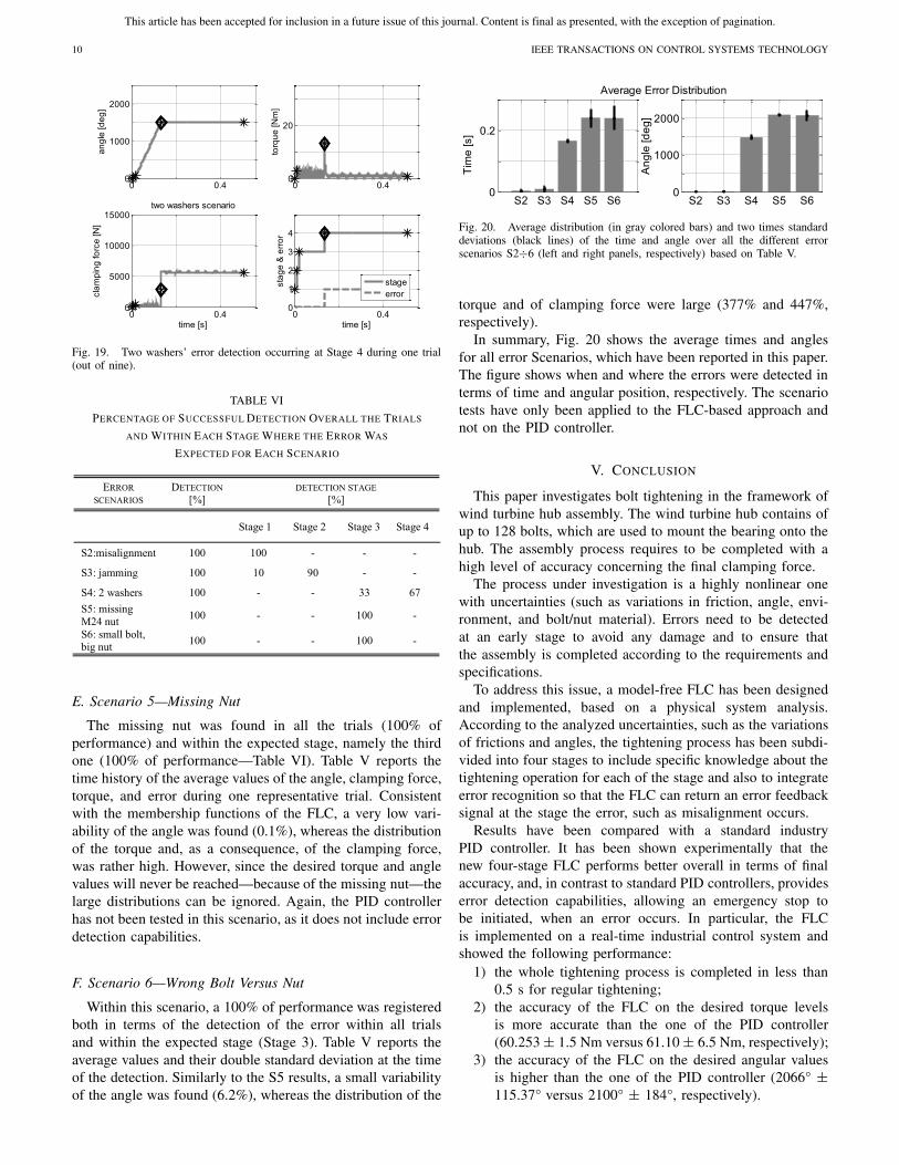
In this scenario, two washers were placed, as shown inFig. 12 and the tightening process was started. The controllerexhibited a 100% performance over all the nine trials. Thiserror was detected within the expected stage (i.e., Stage 3), inthree out of nine trials (33% of performance); in all the othersix trials, it was detected at the beginning of the Stage 4;because during seven trials, the nut and washers touched theflange, the variability of the clamping force was spread outmore than in other scenarios (139%), whereas transition timeand angle were well centered around their averaged values(3%) and the deviation of the torque settled at a value of125%. Similar to Fig. 15, a representative figure of the timehistory of all the parameters during the insertion two washers’scenario is shown in Fig. 19.
As for all the other scenarios, the PID controller has notbeen tested in this scenario as it does not include errordetection capabilities.
This article has been accepted for inclusion in a future issue of this journal. Content is final as presented, with the exception of pagination.
10 IEEE TRANSACTIONS ON CONTROL SYSTEMS TECHNOLOGY
Fig. 19. Two washers’ error detection occurring at Stage 4 during one trial(out of nine).
TABLE VI
PERCENTAGE OF SUCCESSFUL DETECTION OVERALL THE TRIALS
AND WITHIN EACH STAGE WHERE THE ERROR WAS
EXPECTED FOR EACH SCENARIO
E. Scenario 5—Missing Nut
The missing nut was found in all the trials (100% ofperformance) and within the expected stage, namely the thirdone (100% of performance—Table VI). Table V reports thetime history of the average values of the angle, clamping force,torque, and error during one representative trial. Consistentwith the membership functions of the FLC, a very low vari-ability of the angle was found (0.1%), whereas the distributionof the torque and, as a consequence, of the clamping force,was rather high. However, since the desired torque and anglevalues will never be reached—because of the missing nut—thelarge distributions can be ignored. Again, the PID controllerhas not been tested in this scenario, as it does not include errordetection capabilities.
F. Scenario 6—Wrong Bolt Versus Nut
Within this scenario, a 100% of performance was registeredboth in terms of the detection of the error within all trialsand within the expected stage (Stage 3). Table V reports theaverage values and their double standard deviation at the timeof the detection. Similarly to the S5 results, a small variabilityof the angle was found (6.2%), whereas the distribution of the
Fig. 20. Average distribution (in gray colored bars) and two times standarddeviations (black lines) of the time and angle over all the different errorscenarios S2÷6 (left and right panels, respectively) based on Table V.
torque and of clamping force were large (377% and 447%,respectively).
In summary, Fig. 20 shows the average times and anglesfor all error Scenarios, which have been reported in this paper.The figure shows when and where the errors were detected interms of time and angular position, respectively. The scenariotests have only been applied to the FLC-based approach andnot on the PID controller.
V. CONCLUSION
This paper investigates bolt tightening in the framework ofwind turbine hub assembly. The wind turbine hub contains ofup to 128 bolts, which are used to mount the bearing onto thehub. The assembly process requires to be completed with ahigh level of accuracy concerning the final clamping force.
The process under investigation is a highly nonlinear onewith uncertainties (such as variations in friction, angle, envi-ronment, and bolt/nut material). Errors need to be detectedat an early stage to avoid any damage and to ensure thatthe assembly is completed according to the requirements andspecifications.
To address this issue, a model-free FLC has been designedand implemented, based on a physical system analysis.According to the analyzed uncertainties, such as the variationsof frictions and angles, the tightening process has been subdi-vided into four stages to include specific knowledge about thetightening operation for each of the stage and also to integrateerror recognition so that the FLC can return an error feedbacksignal at the stage the error, such as misalignment occurs.
Results have been compared with a standard industryPID controller. It has been shown experimentally that thenew four-stage FLC performs better overall in terms of finalaccuracy, and, in contrast to standard PID controllers, provideserror detection capabilities, allowing an emergency stop tobe initiated, when an error occurs. In particular, the FLCis implemented on a real-time industrial control system andshowed the following performance:
1) the whole tightening process is completed in less than0.5 s for regular tightening;
2) the accuracy of the FLC on the desired torque levelsis more accurate than the one of the PID controller(60.253 ± 1.5 Nm versus 61.10 ± 6.5 Nm, respectively);
3) the accuracy of the FLC on the desired angular valuesis higher than the one of the PID controller (2066° ±115.37° versus 2100° ± 184°, respectively).
This article has been accepted for inclusion in a future issue of this journal. Content is final as presented, with the exception of pagination.
DETERS et al.: ACCURATE BOLT TIGHTENING USING MODEL-FREE FUZZY CONTROL 11
Finally, in terms of error detection, the experimental resultsshow that the FLC is capable to detect all the error scenarioswithin less than 0.5 s, avoiding any physical damage.
REFERENCES
[1] G. M. Joselin Herbert, “A review of wind energy technologies,” Renew.Substainable Energy Rev., vol. 11, no. 6, pp. 1117–1145, 2007.
[2] C. S. Ezio, “Exploitation of wind as an energy source to meet theworld’s electricity demand,” J. Wind Eng. Ind. Aerodyn., vols. 74–76,pp. 375–387, Apr. 1998.
[3] F. Yao, “Theory, desin and applications,” in Handbook of RenewableEnergy Technology. Singapore: World Scientific, 2011, pp. 3–20.
[4] R. Saidur, “A review on global wind energy policy,” Renew. SubstainableEnergy Rev., vol. 14, no. 7, pp. 1744–1762, 2010.
[5] C. Deters, H. A. Würdemann, J. S. Dai, L. D. Seneviratne, andK. Althoefer, “Reconfigurable assembly approach for wind turbinesusing multiple intelligent agents,” in Proc. Adv. Reconfigurable Mech.Robots I, 2012, pp. 95–103.
[6] M. Sharpe, Robotic Fabrication of Wind Turbine Power Generators.YMN, Japan: FANUC Robot., 2009.
[8] Y. Maeda and M. Iwasaki, “Initial friction compensation using rheology-based rolling friction model in fast and precise positioning,” IEEE Trans.Ind. Electron., vol. 60, no. 9, pp. 3865–3876, Sep. 2013.
[9] J. H. J. Potgieter and M. J. Kamper, “Torque and voltage qualityin design optimization of low-cost non-overlap single layer windingpermanent magnet wind generator,” IEEE Trans. Ind. Electron., vol. 59,no. 5, pp. 2147–2156, May 2012.
[10] H. Chaoui and P. Sicard, “Adaptive fuzzy logic control of permanentmagnet synchronous machines with nonlinear friction,” IEEE Trans. Ind.Electron., vol. 59, no. 2, pp. 1123–1133, Feb. 2012.
[11] T. Yokoyama, M. Olsson, S. Izumi, and S. Sakai, “Investigation into theself-loosening behavior of bolted joint subjected to rotational loading,”Eng. Failure Anal., vol. 23, pp. 35–43, Jul. 2012.
[12] H. A. Talebi and K. Khorasani, “A neural network-based multiplicativeactuator fault detection and isolation of nonlinear systems,” IEEE Trans.Control Syst. Technol., vol. 21, no. 3, pp. 842–851, May 2013.
[13] D. A. Dirksz and J. M. A. Scherpen, “Power-based set point control:Experimental results on a planar manipulator,” IEEE Trans. Control Syst.Technol., vol. 20, no. 5, pp. 1384–1391, Sep. 2012.
[14] K. H. Ang, G. Chong, and Y. Li, “PID control system analysis, designand technology,” IEEE Trans. Control Syst. Technol., vol. 13, no. 4,pp. 559–576, Jun. 2005.
[15] J. Villagra, V. Milanes, J. Perez, and C. Gonazalez, “Model free controltechniques for Stop & Go systems,” in Proc. 13th IEEE Annu. Conf.Intell. Transp. Syst., Sep. 2010, pp. 1899–1904.
[16] H. Hanao, S. M. J. R. Fatemi, G. A. Capolino, and S. Sieg-Zieba, “Wirerope fault detection in a hoisting winch system by motor torque andcurrent signature analysis,” IEEE Trans. Ind. Electron., vol. 58, no. 5,pp. 1727–1736, May 2011.
[17] E. L. Secco and G. Magenes, “A feedforward neural network controllingthe movement of a 3-DOF finger,” IEEE Trans. Syst., Man Cybern., A,Syst. Humans, vol. 32, no. 3, pp. 437–445, May 2002.
[18] N. Dhayagude, G. Zhiqiang, and F. Mrad, “Fuzzy logic control ofautomated screw fastening,” Robot. Comput.-Integr. Manuf., vol. 12,no. 3, pp. 235–242, 1996.
[19] S. Izumi, T. Yokoyama, A. Iwasaki, and S. Sakai, “Three-dimensionalfinite element analysis of tightening and loosing mechanism of threadedfastener,” Eng. Failure Anal., vol. 12, no. 4, pp. 604–615, 2005.
[20] T. Fujinaka, H. Nakano, and S. Omatu, “Bolt tightening control usingneural networks,” IEEE Trans. Syst., Man, Cybern., vol. 3, no. 3,pp. 1390–1395, Oct. 2001.
[21] L. D. Seneviratne, F. A. Ngemoh, S. W. E. Earles, and K. A. Althoefer,“Theoretical modelling of the self-tapping screw fastening process,”Proc. Inst. Mech. Eng., C, J. Mech. Eng. Sci., vol. 215, no. 2,pp. 135–154, 2001.
[22] H. A. Mintsa, R. Venugopal, J.-P. Kenne, and C. Belleau, “Feedbacklinearization-based position control of an electrohydraulic servo systemwith supply pressure uncertainty,” IEEE Trans. Control Syst. Technol.,vol. 20, no. 4, pp. 1092–1099, Jul. 2012.
[23] K. Althoefer, L. D. Seneviratne, P. Zavlangas, and B. Krekelberg, “Fuzzynavigation for robotic manipulators,” Int. J. Uncertainty, FuzzinessKnowl.-Based Syst., vol. 6, no. 2, pp. 179–188, 1998.
[24] H. K. Lam, H. Li, C. Deters, H. Würdemann, E. L. Secco, andK. Althoefer, “Control design for interval type-2 fuzzy systems underimperfect premise matching,” IEEE Trans. Ind. Electron., vol. 61, no. 2,pp. 956–968, Feb. 2014.
[25] B. Akin, C. Seungdeog, U. Orguner, and H. A. Toliyat, “A simplereal-time fault signature monitoring tool for motor-drive-embeddedfault diagnosis systems,” IEEE Trans. Ind. Electron., vol. 58, no. 5,pp. 1990–2001, May 2011.
[26] B. U. Xuhui, H. Zhongsheng, and J. Shangtai, “A statistical analysis ofmodel free adaptive control with measurements disturbance,” in Proc.29th Chin. Control Conf., Jul. 2010, pp. 2175–2181.
[27] H. A. Malki, L. Huaidong, and C. Guanrong, “New design and stabilityanalysis of fuzzy proportional-derivative control system,” IEEE Trans.Fuzzy Syst., vol. 2, no. 4, pp. 245–254, Nov. 1994.
[28] M. Sugeno and K. Tanaka, “Successive identification of a fuzzy modeland its application to prediction of a complex system,” Fuzzy Sets Syst.,vol. 42, no. 3, pp. 315–334, 1991.
[29] H. K. Lam and M. Narimani, “Quadratic stability analysis of fuzzymodel based control systems using staircase membership functions,”IEEE Trans. Fuzzy Syst., vol. 18, no. 1, pp. 125–137, Feb. 2010.
[30] K. Althoefer, B. Lara, Y. H. Zweiri, and L. D. Seneviratne, “Automatedfailure classification for assembly with self-tapping threaded fasteningusing artificial neural networks,” Proc. Inst. Mech. Eng., C, J. Mech.Eng. Sci., vol. 222, no. 6, pp. 1081–1095, 2008.
[31] F. Ngemoh, “Modeling the automated screw insertion process,” Ph.D.dissertation, Dept. Eng., King’s College, Univ. London, London, U.K.,1997.
[32] E. Kamal, A. Aitouche, R. Ghorbani, and M. Bayart, “Fuzzy schedulerfault-tolerant control for wind energy conversion systems,” IEEE Trans.Control Syst. Technol., vol. 22, no. 1, pp. 119–131, Jan. 2014.
[33] B. T. Thumati, G. R. Halligan, and S. Jagannathan, “A novel faultdiagnostics and prediction scheme using a nonlinear observer withartificial immune system as online approximator,” IEEE Trans. ControlSyst. Technol., vol. 21, no. 3, pp. 596–578, May 2013.
[34] C. Deters, E. L. Secco, H. A. Würdemann, H. K. Lam, L. D. Seneviratne,and K. Althoefer, “Model-free fuzzy tightening control for bolt/nut jointconnections of wind turbine hubs,” in Proc. IEEE ICRA, May 2013,pp. 270–276.
[35] P. Hajek. (2012 Jun. 13) Fuzzy Logic [Online]. Available:http://plato.stanford.edu/entries/logic-fuzzy/
[36] J. R. Marden, S. D. Ruben, and L. Y. Pao, “A model-free approach towind farm control using game theoretic methods,” IEEE Trans. ControlSyst. Technol., vol. 21, no. 4, pp. 1207–1214, Jul. 2013.
[37] M. Klingajay, L. D. Seneviratne, and K. Althoefer, “Identifica-tion of threaded fastening parameters using the Newton Raphsonmethod,” in Proc. IEEE/RSJ Int. Conf. Intell. Robots Syst., Oct. 2003,pp. 2055–2060.
[38] A. Pisano, A. Davila, L. Fridman, and E. Usai, “Cascade control of PMDC drives via second-order sliding mode technique,” IEEE Trans. Ind.Electron., vol. 55, no. 11, pp. 3846–3854, Nov. 2008.
[39] F. H. F. Leung, H. K. Lam, S. H. Ling, and P. K. S. Tam, “Opti-mal and stable fuzzy controllers for nonlinear systems based on animproved genetic algorithm,” IEEE Trans. Ind. Electron., vol. 51, no. 1,pp. 172–182, Feb. 2004.
[40] C. Westermayer, R. Priesner, M. Kozek, and R. Bauer, “High dynamictorque control for industrial engine test beds,” IEEE Trans. Ind. Elec-tron., vol. 60, no. 9, pp. 3877–3888, Sep. 2012.
Christian Deters received the Dipl.Ing. degreein computer science from Hochschule Bremen,Bremen, Germany, and the M.Sc. degree fromKing’s College London, London, U.K., in 2008 and2009, respectively, where he is currently pursuingthe Ph.D. degree.
His current research interests include control,automation, and manufacturing.
This article has been accepted for inclusion in a future issue of this journal. Content is final as presented, with the exception of pagination.
12 IEEE TRANSACTIONS ON CONTROL SYSTEMS TECHNOLOGY
Hak-Keung Lam (M’98–SM’10) received theB.Eng. (Hons.) and Ph.D. degrees from the Depart-ment of Electronic and Information Engineering,Hong Kong Polytechnic University, Hong Kong, in1995 and 2000, respectively.
He has been with King’s College London, London,U.K., since 2005, where he was a Lecturer and iscurrently a Senior Lecturer. He is the co-editor fortwo edited volumes Control of Chaotic NonlinearCircuits (World Scientific, 2009) and ComputationalIntelligence and Its Applications (World Scientific,
2012), and the co-author of the book Stability Analysis of Fuzzy-Model-Based Control Systems (Springer, 2011). His current research interests includeintelligent control systems and computational intelligence.
Dr. Lam is an Associate Editor for the IEEE TRANSACTIONS ON FUZZY
SYSTEMS and the International Journal of Fuzzy Systems, and serves on theeditorial boards of several journals.
Emanuele Lindo Secco received the M.Sc. degreein mechanical engineering from the University ofPadua, Padua, Italy, and the Ph.D. degree in bio-engineering and medical computer science from theUniversity of Pavia, Pavia, Italy, in 1998 and 2001,respectively.
He is currently a Research Associate with theCentre for Robotics Research, Department of Infor-matics, King’s College London, London, U.K. Hiscurrent research interests include robotics, bio-mimetic systems, sensor integration, and wearable
sensors.
Helge A. Würdemann received the Dipl.Ing. degreein electrical engineering from the Leibniz Universityof Hanover, Hannover, Germany.
He was with the Auckland University of Tech-nology, Auckland, New Zealand, in 2006, and withLoughborough University, Loughborough, U.K., in2007, where he carried out a research project. He iscurrently a Research Associate with the Centrefor Robotics Research, Department of Informatics,King’s College London, London, U.K. His Ph.D.project, which he started in 2008, at King’s College
London was funded by the Engineering and Physical Sciences ResearchCouncil. In 2011, he was with the Research Team of Prof. K. Althoefer,involved in two European Union Seventh Framework Program projects. Hiscurrent research interests include medical robotics for minimally invasivesurgery and self-adaptive control architectures.
Lakmal D. Seneviratne (M’05) received theB.Sc. degree in engineering and the Ph.D. degreein mechanical engineering from King’s CollegeLondon, London, U.K.
He is a Professor of Robotics with Khalifa Uni-versity, Abu Dhabi, United Arab Emirates, on sec-ondment from King’s College London, where he isa Professor of Mechatronics. He has authored morethan 250 refereed research papers related to robot-ics and mechatronics. His current research interestsinclude robotics and autonomous systems.
Dr. Seneviratne is a fellow of the Institution of Engineering and Technologyand the Institute of Mechanical Engineers.
Kaspar Althoefer (M’03) received the Dipl.Ing.degree in electronic engineering from the Univer-sity of Aachen, Aachen, Germany, and the Ph.D.degree in electronic engineering from King’s CollegeLondon, London, U.K.
He is currently the Head with the Centre forRobotics Research, Department of Informatics,King’s College London, where he is a Professor ofRobotics and Intelligent Systems. He has authoredand co-authored more than 200 refereed researchpapers related to mechatronics, robotics, and intelli-