36
15 821 01 a IKA WERKE IKA ® T 65 D Dispersion unit OPERATING INSTRUCTIONS EN/ USA T 65D 042005

15 821 01 a IKA WERKE
IKA® T 65 D Dispersion unit
OPERATING INSTRUCTIONS EN/USA
T 65D 042005


IKA-WERKE T 65 D 042005
CE-KONFORMITÄTSERKLÄRUNG DEWir erklären in alleiniger Verantwortung, dass dieses Produkt den Bestimmungender Richtlinien 89/336EG, 98/37/EG und 73/023EG entspricht und mit denfolgenden Normen und norminativen Dokumenten übereinstimmt:DIN EN 61 010-1; EN 60 204-1; EN 292-1, -2; EN 414; EN 61 326-1.
CE-DECLARATION OF CONFIRMITY ENWe declare under our sole responsibility that this product corresponds to theregulations 89/336EG, 98/37/EG and 73/023EG and conforms with the standards orstandardized documents:DIN EN 61 010-1; EN 60 204-1; EN 292-1, -2; EN 414; EN 61 326-1.
DÉCLARATION DE CONFORMITÉ CE FRNous déclarons sous notre propre responsabilité que se prodiut est conforme auxréglementations 89/336EG, 98/37/EG et 73/023EG et en conformité avec lesnormes ou documents normalisés suivant:DIN EN 61 010-1; EN 60 204-1; EN 292-1, -2; EN 414; EN 61 326-1.
DECLARACION DE CONFORMIDAD DE CE ESDeclaramos por nuestra responsabilidad propia que este produkto corresponde alas directrices 89/336EG, 98/37/EG y 73/023EG y que cumple las normas odocumentos normativos siguientes:DIN EN 61 010-1; EN 60 204-1; EN 292-1, -2; EN 414; EN 61 326-1.
CE-DICHIARAZIONE DI CONFORMITÀ ITDichiariamo, assumendone la piena responsabilità, che il prodotto è conforme alleseguenti direttive: 89/336EG, 98/37/EG e 73/023EG, in accordo ai seguentiregolamenti e documenti:DIN EN 61 010-1; EN 60 204-1; EN 292-1, -2; EN 414; EN 61 326-1.

IKA-WERKE T 65 D 042005
Explanation of symbols
This symbol identifies information that is of vital importance for safeguardingyour health and safety. Disregarding this information can lead to health impairmentand injuries.
This symbol identifies information that is of importance for the technicallycorrect functioning of the system. Disregarding this information can result indamage to the T 65 D dispersion unit or to system components.
This symbol identifies information and notes that are of importance for correcthandling of the T 65 D dispersion unit.
+

IKA-WERKE T 65 D 042005
Page I-1
Contents
Page
1 Notes for the user .................................................................... 1-1
1.1 Correct use ............................................................................ 1-1
1.2 For your safety........................................................................ 1-1
1.3 Guarantee .............................................................................. 1-2
2 Product description.................................................................. 2-1
2.1 The T 65 D dispersion unit........................................................ 2-1
2.2 Dispersion tools in the S 65 range ............................................. 2-2
2.3 T 653 telescopic stand ............................................................. 2-3
3 Set-up and commissioning ....................................................... 3-1
3.1 Unpacking .............................................................................. 3-1
3.2 Assembly and electrical installation of the dispersion unit ............. 3-1
3.3 Mounting the safety limit switch................................................. 3-2
3.4 Pre-assembly of dispersion tools ............................................... 3-2
3.5 Mounting the dispersion tool on the unit ..................................... 3-4
3.6 Switching the unit on ............................................................... 3-5
4 Maintenance and care............................................................... 4-1
4.1 T 65 D dispersion unit .............................................................. 4-1
4.2 Dispersion tools ...................................................................... 4-2
4.3 Changing the slide ring seal...................................................... 4-3
5 Technical data.......................................................................... 5-1
5.1 T 65 D dispersion unit technical data ......................................... 5-1
5.2 S 65 dispersion tool technical data ............................................ 5-2
6 Accessories ............................................................................. 6-1
7 Appendix ................................................................................. 7-1
7.1 T 65 D dispersion unit spare parts diagram and list ...................... 7-1
7.2 S 65 range spare parts diagram and list ..................................... 7-2
7.3 Wiring diagram of T 65 D dispersion unit .................................... 7-3
7.4 Applicable standards and regulations ......................................... 7-4
7.5 The T 653 telescopic stand....................................................... 7-5

IKA-WERKE T 65 D 042005

IKA-WERKE T 65 D 042005
Page 1-1
1 Notes for the user
1.1 Correct use
The T 65 D dispersion unit, used in conjunction with the IKA dispersion tools, issuitable for mixing, emulsifying and dispersing free-flowing and liquid media in batchoperation. It is designed for use in technical colleges and for small-scale production.For operation, the T 65 D dispersion unit must be mounted on the T 653 telescopicstand. It must only be used with dispersion tools from the S 65 range.
1.2 For your safety
For correct use, the unit must be secured on the T 653 telescopic stand by twobolts, in accordance with Section 3 "Set-up and commissioning". The telescopicstand must be installed so that it cannot topple over or slide about, and must beequipped with a safety disconnection device which operates when the stand ismoved upwards. In particular, please also read the safety notes for use of thetelescopic stand (see Appendix, Section 7.5, "The T 653 telescopic stand).
The unit is not suitable for manual operation. Please observe the applicablesafety notes and directives, as well as health and safety regulations andsafety rules for use in the laboratory.
If the emergency stop switch of the dispersion unit is not within reach whenthe unit is operating, an additional emergency stop switch must be installedwithin easy reach, in the working area.
During operation never touch the dispersion tools to avoid injury. Somedispersion tools have overlapping cutting edges and teeth.
When working with the dispersion unit, the user must select and wear his/herpersonal protection equipment to suit the danger class of the product to bemixed. With faulty or unsuitable protection equipment, the user can beendangered due to splashing.
The T 65 D dispersion unit must not be used in hazardous areas, fordispersing hazardous substances, or used for operation under water.
The T 65 D dispersion unit must not be used for processing any inflammableor combustible materials.
Only dispersion tools approved by IKA for this unit must be used.
Imbalance of the dispersion unit tool shaft can lead to uncontrolled resonancebehaviour of the unit and the entire installation. Glass apparatus and vessels can bedamaged or can shatter, and if this happens, the user could be injured. If unevenrunning of the unit is noticed, the dispersion tool should be checked and replaced ifnecessary.
The vessels used for the dispersing process must be secured. Glass vessels mustalways be secured with a clamp to prevent them spinning. When working in glassvessels, the dispersion tool must not come into contact with the glass. Either elasticcouplers must be used when working with flasks, or sufficient clearance maintainedbetween dispersion tool and vessel, in order to avoid glass breakage.
Operatingconditions
Danger due toglass breakage

1 Notes for the user
IKA-WERKE T 65 D 042005
Page 1-2
In some circumstances, the region between medium and drive shaft, or betweenrotor and stator, can become electrostatically charged, and ignite an explosiveatmosphere caused by evaporation of the medium. In addition, with advancedevaporation of the medium, the slide ring seal can overheat to such an extent that itwould lead to an ignition or combustion of the medium.
For this reason, no inflammable or combustible materials must be processed withthe T 65 D dispersion unit.
Before commissioning, the unit must be wired up by a skilled worker.
Even in the case of repair work, the unit must only be opened by a skilled worker.Before opening, the mains plug must be pulled out. Live parts inside the unit canremain live for a long time after the mains plug is pulled out.
The accessory must only be fitted after the mains plug is disconnected.
The handwheel bolt on the flange of the drive unit can become loose due tovibration. For safety's sake, check the tightness of the handwheel bolt regularly, andretighten it if necessary.
Before commissioning, the correct direction of rotation of the motor must always beensured (test run without dispersion tool: motor rotation as indicated on the arrowplate, or clockwise rotation, looking down on motor). The wrong direction of rotationcan lead to the rotor or stator coming off the shaft.
If the unit is operated in different locations with a 5-pin plug, the direction of rotationmust be checked before commissioning, with no dispersion tool fitted.
Ventilation slots and cooling vanes on the motor must not be covered.
Avoid shocks or impacts on the dispersion tool. Even slight, undetectable damageleads to imbalance and uneven running of the drive shaft. Careful handling ensuresthe safe operation and durability of the unit.
If possible, only switch on the drive with the lowest speed (in combination with aspeed controller DS). Increase the speed slowly to the desired value.
Dispersion tools must only be operated in the medium. The sealing surfaces arecooled by the free-flowing medium. Running dry destroys the sealing surfaces.
Never use the dispersing unit without dispersion tools.
Rapid temperature change (thermal shock!) can destroy the hard metal sealingsurfaces.
In order to avoid high risk of injury never touch the dispersion tool during operation!Some dispersion tools have prominent blades and teeth.
1.3 Guarantee
You have purchased an original IKA laboratory machine which meets the highestengineering and quality standards. In accordance with IKA guarantee conditions, theguarantee period is 24 months. For claims under the guarantee please contact yourlocal dealer. You may also send the machine direct to our works, enclosing thedelivery invoice and giving reasons for the claim. You will be liable for freight costs.
Danger due toelectric shock
Checking thehandwheel bolt
Impairment ofthe machinefunction
Observedirection ofrotation ofthe motor
Danger due toexplosion oroverheating

IKA-WERKE T 65 D 042005
Page 2-1
2 Product description
2.1 The T 65 D dispersion unit
The IKA T 65 D dispersion unit is a high-quality product that guarantees trouble-free use, as a result of the sturdy unit construction and the simple operation. Thedrive shaft - driven by a Poly-V-belt – has a fixed speed of 7200 r.p.m. and, in turn,drives the rotor. As a result, the S 65 range of dispersion tools that can be usedachieve tip speeds of 21.9 m/sec. These tip speeds lead to optimal dispersing oremulsifying results in batch operation.
For operation, the T 65 D dispersion unit must be mounted on the IKA T 653telescopic stand. It must only be operated with the S 65 KG-HH shaft and thedispersion tools from the S 65 range (G 65 G, G 65 M, G 65 F). The unit is switchedon and off by pressing the ON button (A) and the emergency stop button (B). If theemergency stop switch of the dispersion unit is not within reach, an additionalemergency stop switch must be installed within easy reach, in the working area.
If the telescopic stand is moved upwards when the unit is operating, the dispersionunit must switch off. To facilitate this, the telescopic stand must be equipped with asafety disconnection device. For this purpose, we recommend the installation of theSI 400 safety limit switch together with the SI 400 mounting support (accessories).
Safetydisconnectiondevice

2 Product description
IKA-WERKE T 65 D 042005
Page 2-2
The unit is supplied without connecting cable, as the installations on the user'spremises do not permit a standard cable length, because of the differentaccommodating spaces. The layout of connections is shown in the wiring diagram(see Section 6.3 "Wiring diagram"), for the information of skilled workers.
The unit heats up in service. The generously-proportioned cooling surfaces on themotor achieve an even distribution and emission of the heat.
The AC motor runs in ball bearings and is maintenance-free. In its attached controlcabinet, it has a special safety device for operation on overcurrent and undervoltage(undervoltage trip), to permanently switch the motor off and avoid any thermaldamage. The unit can only be put back in service when the power supply requiredfor the motor is restored.
The basic connection and performance data for the motor can be obtained from themotor rating plate.
The connection facility for the IKA SI 400 safety limit switch is also provided in themotor control cabinet.
2.2 Dispersion tools in the S 65 range
A dispersion tool in the S 65 range consists of a shaft and a generator (stator/rotor).The shaft carries the marking S 65 KG-HH, where KG stands for the ball bearingand HH for a slide ring seal made of hard metal. The seal prevents liquid rising upthe shaft and destroying the ball bearing. The top end of the shaft is in the form of aplug-in coupling. The bottom end of the shaft carries a thread for mounting thestator. The shaft – running in ball bearings- carries the rotor.
For the S 65 range, there are three types of generator, designated G 65 G, G 65 M,G 65 F, where the prefix G stands for generator and the suffices G for coarse, M formedium and F for fine. The appropriate generator must be used according to themedium. When the starting material is too coarse for the generator, the generatorcan clog up and hence become ineffective. In addition, the sealing surfaces run dry,so that they are damaged.
The generators are suitable for solids components with the following grain sizes:
Generator type Grain size
G 65 G 40 mm
G 65 M 8 mm
G 65 F 1 mm
It can often be helpful to process a medium with all three generators in sequence,starting with generator G 65 G. Although it is easy to change the generators, in suchcases, it is worth buying three shafts, that can then be changed with fewermanipulations.
Motorprotection
Wiring byskilled worker

IKA-WERKE T 65 D 042005
Page 2-3
Due to the high rotation speed of the rotor, the medium to be processed isautomatically drawn axially into the dispersion head and then forced radially throughthe slots in the rotor/stator arrangement. The high accelerations acting on thematerial produce extremely strong shear and thrust forces. In addition, highturbulence occurs in the shear gap between rotor and stator, which providesoptimum mixing of the suspension.
The dispersion effectiveness is heavily dependent on the product of the sheargradient and the time the particles spend in the shear zone. The optimum range forthe circumferential velocity of the rotor/stator arrangement is 10 to 24 m/s.
A processing time of a few minutes is usually sufficient to produce the desiredfineness. Long prccessing times bring only insignificant improvements in theobtainable fineness; the energy expended serves merely to increase thetemperature of the medium.
With small quantities, a rapid heating-up of the medium must be expected,because of the high motor power, which is mainly converted into heat.
If the viscosity of the material to be processed is too high (above about 5Pas.), or the vapour pressure of the liquid is very high, the flow is unable tofollow the rapid accelerations of the generator, and breaks down. This leads todry running, and hence to destruction of the sealing surfaces. Suchsubstances must be fed to the generator by force. Use a continuous flow unit(i.e. IKA Laborpilot) for this, and/or an additional pump.
2.3 T 653 telescopic stand
In conjunction with the IKA T 653 telescopic stand, the T 65 D dispersion unit canalso be used for tall mixing vessels. For information on this product, please refer tothe Appendix to this document.
The rotor/statorprinciple

IKA-WERKE T 65 D 042005

IKA-WERKE T 65 D 042005
Page 3-1
3 Set-up and commissioning
3.1 Unpacking
Please unpack the system components carefully and check closely for any damage.It is important to recognize any damage that occurred during shipping while you areunpacking. If damage has occurred, you will need to make a written assessment ofthe damage and send it to us by mail, rail or special delivery.
The delivery package of the unit comprises: one T 65 D dispersion unitcorresponding to the type ordered (see Section 5, "Technical data"), one set of toolsand one set of operating instructions.
3.2 Assembly and electrical installation of the dispersion unit
As shown in the diagram, the T 65 D dispersion unit is mounted on the T 653telescopic stand with two M12 hexagon socket head (Allen) screws and toothed lockwashers. The screws and toothed lock washers are included in the delivery packageof the stand. An assistant is required for screwing on the T 65 D dispersion unit.
Mounting thedispersion unit

3 Set-up and commissioning
IKA-WERKE T 65 D 042005
Page 3-2
The telescopic stand must be installed such that it does not tilt or slide about.It must not move about when the unit is operating.
Particular danger points, such as crushing/trapping positions, rotating parts,locking screws for the stand column, are identified by an exclamation mark inthe “Dispersion unit assembly” diagram. Particular regard should be paid tothese danger points when the unit is in service!
The electrical connections of the T 65 D dispersion unit must be made by a skilledworker in accordance with the wiring diagram (see Section 6.3, “Wiring diagram”).
3.3 Mounting the safety limit switch
There is a danger of trapping between the safety limit switch, switch contactand the end stop!
Mount the SI 400 safety limit switch together with the SI 474 mounting support onthe T 653 telescopic stand. For this, follow the mounting instructions on the nextpage.
3.4 Pre-assembly of dispersion tools
Before the dispersion tools are connected to the dispersion unit, the shaft andgenerator are pre-assembled. The following tools (set of tools included in the T 65 Ddelivery package) are required to change the generator:
Rotor wrench
Hook wrench
Shaft wrench
The slide ring seal must be correctly fitted before pre-assembly of the shaftand generator.

IKA-WERKE T 65 D 042005
Page 3-3

3 Set-up and commissioning
IKA-WERKE T 65 D 042005
Page 3-4
Assemble the generator on the shaft as follows:
1. Screw the stator on to the stator tube counterclockwise by hand. Note the left-hand thread!
2. Gently tighten the stator with the hook wrench. The stator is turned in the samedirection later, by the flow pressure of the rotor, and hence cannot come loose.
3. Screw the rotor clockwise on to the shaft (right-hand thread). To do this, holdthe shaft with the shaft wrench at the coupling section and tighten the rotor withthe rotor wrench. With the G 65 G generator, the rotor wrench is insertedbetween the teeth of the stator and turned.
3.5 Mounting the dispersion tool on the unit
The dispersion tool must only be mounted on the dispersion unit when themains plug is pulled out and the drive shaft is stationary.
The pre-assembled element, consisting of shaft and generator, is now connected tothe T 65 D dispersion unit. To do this, insert the pre-assembled dispersion tool in thedispersion tool receptacle (C) and secure it with the handwheel bolt. Make sure thatthe shaft is inserted right up to the stop in the receptacle. It can be helpful to turn theshaft lightly as it is inserted. The tool is locked in position by tightening thehandwheel bolt. Make sure that the handwheel bolt is securely tightened, and alsocheck the tightness frequently when the unit is in service.

IKA-WERKE T 65 D 042005
Page 3-5
3.6 Switching the unit on
Check that the voltage stated on the rating plate matches the available mainssupply voltage. The socket used must be earthed (protective earth contact). Ifthese condition are fulfilled, the unit is ready for service, after the mains plugis inserted. Otherwise, safe operation cannot be guaranteed, or the unit can bedamaged.
Before switching the unit on, the dispersion tool must be immersed to the minimumimmersion depth in the medium (see Section 5, “Technical data”). Because of thesuction effect, the clearance to the base of the vessel must not be less than 30 mm.The dispersion tool must be brought into the vessel off-centre, to avoid rotationalturbulence (vortexing).
For safety's sake, the vessel must always be well secured.
When operating with the SI 400 safety limit switch, the unit is only ready for servicewhen it has been locked in position at the planned working height and the switchcontact operates the safety limit switch.
The unit is started by pressing the ON button (A).
The unit is stopped by pressing the EMERGENCY STOP button (B).
After an interruption in the power supply, or a mechanical interruption during adispersing process, the unit does not automatically re-start.+

IKA-WERKE T 65 D 042005

IKA-WERKE T 65 D 042005
Page 4-1
4 Maintenance and care
4.1 T 65 D dispersion unit
The Poly-V-belt should be retightened after about 50 operating hours. To do this,proceed as follows:
1. Slacken off the four hexagon head bolts near the motor using a 13mm a/fwrench.
2. Pull the motor in direction F with a force of about 100 N, as shown in thediagram.
3. Retighten the bolts whilst still applying the force.
Apart from this, the T 65 D operates maintenance-free. It is simply subject to thenatural ageing of the components and their statistical failure rate.
When ordering spare parts, please quote the serial number and unit type stated onthe rating plate, together with the item number and designation of the spare part.
Only send units back for repair that have been cleaned and are free fromsubstances hazardous to health.

4 Maintenance and care
IKA-WERKE T 65 D 042005
Page 4-2
When cleaning IKA devices, use only these cleaning agents that are approved byIKA:
Type of dirt Cleaning agent
• Paint Isopropanol• Construction materials Water with detergent, isopropanol• Cosmetics Water with detergent, isopropanol• Food Water with detergent• Fuels Water with detergent• Substances not named Please inquire with IKA
We also recommend that you wear gloves while cleaning. Electrical devices mustnot be placed in the cleaning agent for cleaning purposes.
4.2 Dispersion tools
The shaft must be cleaned immediately after the unit has been used. This preventsany substance residues adhering to the rotor and stator threads, or bacteria culturesforming in undesired places.
Run the dispersion tool in a solvent which will dissolve substance residues but notharm the seals. As a result, because of the high flow speeds, the rotor and stator willthen only be lightly soiled.
Do not put the dispersion tool in a vessel containing solvent to dissolvesubstance residues. The seals are mainly dynamic-acting, and quickly start toleak when stationary.
Clean the dispersion tools and shaft as follows:
1. With the drive switched off, dismount the dispersion tool from the drive byslackening the handwheel bolt.
2. Unscrew the generator from the shaft.The disassembly procedure is the reverse of the assembly procedure (seeSection 3.2 “Pre-assembly of dispersion tool”).
The stator can be very tightly seated on the shaft tube, particularly whenworking with viscous substances, or when cleaning has been neglected, orwhen medium has penetrated into the thread between shaft tube and stator. Inthis case, the shaft tube can be held in a vice with soft jaws to crack the thread.Note the left-hand thread!
Cleaning theshaft andgenerator

IKA-WERKE T 65 D 042005
Page 4-3
3. Rinse all threads and clean them with a brush if necessary.
The shaft and dispersion tool can now be pre-assembled again, ready for use.
Wet chemical methods are permissible for sterilization and disinfection of thedispersion tools. Many instances of disinfection can be solved by means ofbactericidal solutions. It is important that the remains of the disinfectant aresubsequently removed with sterilized water.
No moisture must be allowed to enter the ball bearing, so, basically, the upperend of the shaft tube must be sealed (e.g. with silicone plugs)
Other sterilization methods (e.g. moist heat 120 °C at 2 bar, or killing thebacteria with hot air at 160 °C to 190 °C) are not allowed.
The correct functioning of the generator essentially depends on the sharpness of theedges of the tooth crests on the rotor and stator. The edges can wear with abrasivemedia, reducing the effectiveness of the dispersion.
When ordering spare parts, please quote the type of the dispersion tool and thedesignation of the spare part
The seals in the shafts must be regularly inspected. In the event of leakage,the suction effect of the rotating spindle can cause the medium to rise up theshaft and enter the drive unit.
4.3 Changing the slide ring seal
To prevent damage to the unit, the slide ring seal must only be changed by askilled mechanical person.
Sterilization anddisinfection
Maintenance

4 Maintenance and care
IKA-WERKE T 65 D 042005
Page 4-4
To change the slide ring seal and the ball bearings, proceed as follows:
1. Unscrew the three grub screws (D) and pull the lower part of the slide ring seal(E) downwards and remove. This will now free the lock ring (F). Pull down andremove the lock ring.
2. In order to be able to change the ball bearings you must first dismantle theoutput shaft. To do this, remove the circlip (G) using a pair of circlip pliers andthen push the output shaft upwards and out of the tube. The upper ball bearing(I) will slide out of the shaft tube together with the shaft. Remove the cross pin(J) and the circlip (K) and slide the upper ball bearing off the shaft. Remove thelower ball bearing from below.
Caution: When dismantling dirty units which are difficult to dismantle you shouldavoid striking or knocking the output shaft. Do not strike the output shaft.Knocking or sharp blows will damage the shaft.
3. Reassembly. Fit the ball bearing (I) and the cross pin (J) to the shaft and thenslide this assembly into the shaft tube from above. Fix the shaft in place with thecirclip (G). Slide the lower ball bearing (H) onto the shaft and then into the shafttube. Fit the lock ring (F) and then the bearing ring seal (E).
4. When you have finished reassembly, you should adjust the contact pressure ofthe two seal surfaces. Before you tighten the assembly, adjust the contactpressure so that the inner part of the bearing ring seal (E) is pushed tight upagainst the outer part (clearance 0 mm

IKA-WERKE T 65 D 042005
Page 5-1
5 Technical data
5.1 T 65 D dispersion unit technical data
Motor dataRated voltage [V AC] 3 x 400 Y 3 x 230 ? 3 x 400 Y 3 x 230 ?Rated frequency [Hz] 50 50 60 60Motor speed [r.p.m.] 2880 2850 3520 3520Power consumption [W] 1943 1943 2381 2381Power output [W] 1500 1500 1800 1800
Additional dataShaft speed 7200 r.p.m.Tip speed 21.9 m/secPerm. duty cycle 100 %Ingress protection to DIN 40 050 IP 54Overvoltage category IIProtection class I (protective earth)Pollution degree 2Protection on overload Overcurrent and undervoltage switch on the
AC motorPerm. ambient temperature +5 °C to +40 °CPerm. relative humidity 80 %Operating position On the stand, dispersion tool vertically
downwardsDrive Vane-cooled AC motor with Poly-V-belt drive
transmission stageStand mounting Flange in lower section of housingHousing AluminiumMax. dimensions (W x H x D) 190 mm x 580 mm x 380 mmWeight 28 kgUse at altitude (above NSL) max. 2000 m

5 Technical data
IKA-WERKE T 65 D 042005
Page 5-2
5.2 S 65 dispersion tool technical data
S 65 KG-HH- G 65 G G 65 M G 65 FWorking range 2 l - 50 l 2 l - 40 l 2 l - 30 lStator diameter 65 mm 65 mm 65 mmRotor diameter 58 mm 58 mm 58 mmCircumferential speed 21.9 m/s 21.9 m/s 21.9 m/sMin. / max. immersiondepth
90 mm / 450 mm 80 mm / 450 mm 80 mm / 450 mm
Shaft length 520 mm 510 mm 500 mmMaterials in contact withmedium
FFPM / SIC,AISI 316L
FFPM / SICAISI 316L
FFPM / SIC,AISI 316L
pH range 2 - 13 2 - 13 2 - 13Suitable for solvents yes yes yesSuitable for abrasivesubstances
no no no
Max. temperature 180 °C 180 °C 180 °CSterilization methods wet chemical wet chemical wet chemicalMin. vacuum 1 mbar 1 mbar 1 mbarMax. pressure 6 bar 6 bar 6 barUltimate fineness,suspensions
25 µm - 75 µm 20 µm - 50 µm 5 µm - 20 µm
Ultimate fineness,emulsions
5 µm - 25 µm 5 µm - 15 µm 1 µm - 10 µm
Slide ring seal tungsten carbide+ 6 % cobalt
tungsten carbide+ 6 % cobalt
tungsten carbide+ 6 % cobalt
O-rings FKM FKM FKMOther parts stainless steel
AISI 316Lstainless steelAISI 316L
stainless steelAISI 316L
Quantity detailsThe quantities processed are limited, in particular, by the viscosity of the medium:
Viscosity Volume0,001 Pas max. 30 l0,1 Pas max.10 l1,0 Pas max. 5 l5,0 Pas max. 3 l
At higher viscosities, a breakdown of the flow and dry-running conditions for the sealmust be expected.
Consideration of flow anomaliesThe quantity details given above apply for Newtonian fluids. Processing ofsubstances with thixotropic or dilatant (shear thickening) behaviour is possible, butthe particular volumes must always be determined by trials.

IKA-WERKE T 65 D 042005
Page 6-1
6 Accessories
Order designation
T 653 Telescopic standSI 400 Safety limit switchSI 474 Support holderS 65 KG-HH ShaftS 65 KG-HH-G 65 G Dispersion tool - coarseS 65 KG-HH-G 65 M Dispersion tool - mediumS 65 KG-HH-G 65 F Dispersion tool - fine

IKA-WERKE T 65 D 042005

IKA-WERKE T 65 D 042005
Page 7-1
7 Appendix
7.1 T 65 D dispersion unit spare parts diagram and list
Item Designation1 Toothed lock washer - DIN 6797 - A 8.4_13 Hexagon head screw - ISO 4017 - M8 X 20_14 Countersunk screw - ISO 7046-1 - M8 X 16 - 4.5 Cheese-head screw6 Grub screw - DIN 916 - M8 X 12_17 Grub screw_19 Washer - DIN 125 - A 8.4_110 Retaining ring - DIN 471 - 14 X 1_111 Ball bearing compensating disc12 Adjusting spring - A 5 X 5 X 20 - DIN 6885_113 Grooved ball bearing - DIN 625 T1 - 6002 - 114 Retaining ring - DIN 472 - 32 X 1.2_116 Warning plate17 Front plate18 Arrow plate19 Poly-V-belt20 AC motor22 Handwheel bolt24 Transmission housing25 Cover26 Access plate27 Supporting plate28 Bearing bush29 Drive shaft31 Coupling32 V-belt pulley
Spare partsdiagram forT 65 D unit
Spare parts listfor T 65 D unit

7 Appendix
IKA-WERKE T 65 D 042005
Page 7-2
Item Designation33 V-belt pulley38 Stuffing gland40 Flat headed screw with cross-slot - ISO41 Motor protection relay42 Lock nut DIN 4632043 Direct on-line motor starter44 Terminal strip
7.2 S 65 range spare parts diagram and list
Item Designation1 Protective cover3 Grooved pin4 Grooved ball bearing5 Grooved ball bearing6 Retaining ring8 Retaining ring15 Shaft tube16 Shaft20 Stator 65 G21 Rotor 65 G22 Stator 65 M23 Rotor 65 M24 Stator 65 F25 Wing plate 65 F26 Rotor 65 F2001 O-ring 15 x 2.0 FFPM2002 O-ring 22 x 2.5 FFPM2003 O-ring 30 x 2.5 FFPM5001 Slide ring seal
Spare partsdiagram forS 65 range
Spare parts listfor S 65 range
IKA-WERKE T 65 D 042005
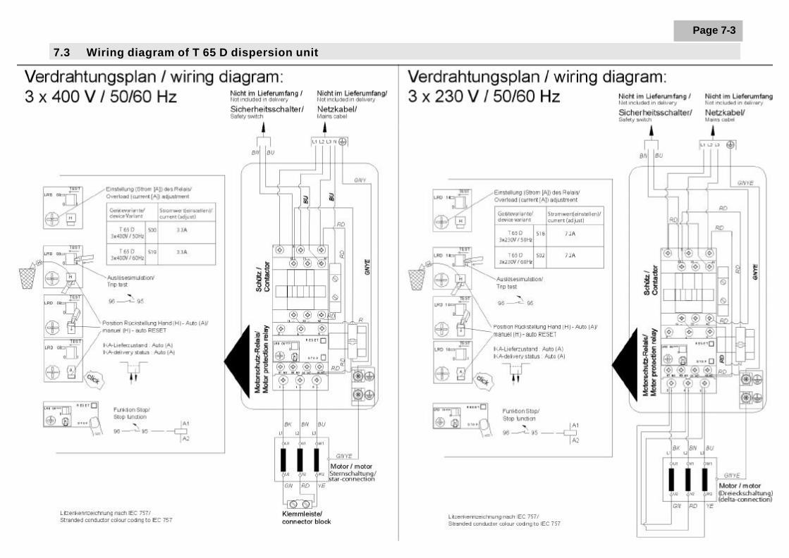
Page 7-3
7.3 Wiring diagram of T 65 D dispersion unit

7 Appendix
IKA-WERKE T 65 D 042005
Page 7-4
7.4 Applicable standards and regulations
Applicable EU DirectivesEMC Directive: 89/336/ECLow-voltage Directive: 73/023/ECMachinery Directive: 98/37/EC
Construction in accordance with the following safety standardsIEC 1010-1EN 61 010-1EN 60 204-1EN 292-1, -2EN 414UL 3101.1CAN/CSA C22.2 (1010.1).
Construction in accordance with the following EMC standardsEN 61 326-1IEC 61 326-1

IKA-WERKE T 65 D 042005
Page 7-5
7.5 The T 653 telescopic stand
The T 653 telescopic stand is used solely for mounting IKA T 65 D dispersion units.For correct use, the following safety notes and the safety notes in the operatinginstructions for the T 65 D must be strictly observed.
• The stand pillar must be inserted into the baseplate so that the guide groove isat the back. Other alignments are not permissible, as otherwise the stand cantopple over when a unit is mounted on it.
• The telescopic stand must be set up level and secure on the floor. Any smallunevennesses that cause the stand to rock must be compensated for with theheight-adjustable feet.
• The T 65 D dispersion unit must be lifted on to the guide head of the telescopicstand with the aid of an assistant, and secured with the two screws and toothedlock washers (supplied), in accordance with the T 65 D operating instructions.The unit must be mounted in front, vertically above the baseplate; a differentalignment is not permissible, as otherwise the assembly could topple over.
• This telescopic stand must be fitted with a safety disconnection device, whichstops the unit if the stand is moved upwards when the unit is operating.
• Switch the unit off before moving the telescopic stand upwards.
• When lowering the telescopic stand, take care that no parts of the body getbetween the safety switches (danger of crushing).
• Only switch the unit on when the dispersion tool is in the vessel.
• The handwheel bolt on the stand can come loose due to vibration, which wouldlead to the unit moving down. So, check the tightness of the handwheel boltregularly when using the unit, and retighten it if necessary.
• Raise or lower the stand (after slackening the handwheel bolt) by applying themanual force as close as possible to the stand pillar. The further the force isapplied from the pillar, the more force you need to apply, plus there is anincreased risk of the equipment toppling over.
• Secure the vessel against spinning round, by using a clamp, for example.
Safety notes
Applicability

7 Appendix
IKA-WERKE T 65 D 042005
Page 7-6
You have purchased an original IKA laboratory machine which meets the highestengineering and quality standards. In accordance with IKA guarantee conditions, theguarantee period is 24 months. For claims under the guarantee please contact yourlocal dealer. You may also send the machine direct to our works, enclosing thedelivery invoice and giving reasons for the claim. You will be liable for freight costs.
Please unpack the telescopic stand carefully and check closely for any damage. It isimportant to recognize any damage that occurred during shipping while you areunpacking. If damage has occurred, you will need to make a written assessment ofthe damage and send it to us by mail, rail or special delivery.
The delivery package of the unit comprises: one telescopic stand T 653 and oneoperating instructions. For technical reasons associated with shipping, thetelescopic stand is supplied stripped down, as pre-assembled modules.
The stand pillar is inserted into the baseplate so that the guide groove is at the back.The black handwheel bolt is then on the right. The stand pillar is then secured frombelow with a hexagon nut, toothed lock washer and a large shaped washer.
All 4 rubber feet are height-adjustable, so the stand can be set up so it does notrock, even on uneven floors.
Guarantee
Unpacking
Setting upthe stand

IKA-WERKE T 65 D 042005
Page 7-7
The T 65 D dispersion unit is placed on the arm of the stand and bolted on frombelow with the bolts supplied. The help of an assistant is needed for screwing on theT 65 D dispersion unit.
The cable clips included in the delivery package are required for fixing the powercable of the unit.
The height-adjustable telescopic stand must be fitted with a safety disconnectiondevice. We recommend installation of the SI 400 safety limit switch together with theSI 474 clamp support. You will find information on their installation in the operatinginstructions of this unit, see side 3.3.
The stand can be raised and lowered by loosening the handwheel bolt. The integralgas shock absorber helps to keep the manual force needed for this as light aspossible. The manual force must be applied close to the stand pillar, so that thestand can be raised and lowered with only a slight use of force. If the force forraising or lowering is applied at a distance from the stand pillar, a turning momentresults, leading to increased friction on the pillar guide. As a result, the stand canonly be moved with great difficulty, or cannot be moved at all. Besides this, thedanger of the stand toppling over is increased.
When the unit is at the correct height, the handwheel bolt is tightened by hand.Check the tightness of the handwheel bolt regularly when using the unit, andretighten it if necessary.
The stand pillar must always be lightly oiled, so that raising and lowering is notmade more difficult due to increased friction. Apart from this, the telescopic stand ismaintenance-free.
When ordering spare parts, please quote the serial number and unit type stated onthe rating plate, together with the item number and designation of the spare part.
Only send units back for repair that have been cleaned and are free fromsubstances hazardous to health.
When cleaning IKA devices, use only these cleaning agents that are approved byIKA:
Type of dirt Cleaning agent
• Paint Isopropanol• Construction materials Water with detergent, isopropanol• Cosmetics Water with detergent, isopropanol• Food Water with detergent• Fuels Water with detergent• Substances not named Please inquire with IKA
We also recommend that you wear gloves while cleaning. Electrical devices mustnot be placed in the cleaning agent for cleaning purposes.
Mountingthe unit
Safetydisconnectiondevice
Commissioning
Maintenanceand cleaning

7 Appendix
IKA-WERKE T 65 D 042005
Page 7-8
SI 400 Safety limit switchSI 474 Support holder
Accessories


IKA-WERKE T 65 D 042005
ErsatzteillisteR 474


