23
Illinois State University BIM Project Execution and Standards Guide V.1 November 1, 2013
Illinois State University
BIM Project Execution and Standards Guide V.1
November 1, 2013


TABLE OF CONTENTS
SECTION A: BIM PROJECT EXECUTION PLAN OVERVIEW............................................................................... 1 SECTION B: PROJECT INFORMATION............................................................................................................. 2 SECTION C: KEY PROJECT CONTACTS ............................................................................................................ 3 SECTION D: PROJECT GOALS / BIM USES ....................................................................................................... 3 SECTION E: BUILDING INFORMATION MODELING FILE TYPES ...................................................................... 4 SECTION F: BIM AUTHORING AND COLLABORATION SOFTWARE REQUIREMENTS.................................. 6 SECTION G: COLLABORATION PROCEDURES ................................................................................................. 7 SECTION H: FILE NAMING CONVENTION ...................................................................................................... 8 SECTION I: QUALITY CONTROL ..................................................................................................................... 10 SECTION J: TECHNOLOGY INFASTRUCTURE REQUIREMENTS ...................................................................... 10 SECTION K: MODEL STRUCTURE ................................................................................................................... 11 SECTION L: PROJECT DELIVERABLES ............................................................................................................. 12 SECTION M: DELIVERY STRATEGY & LOD – LEVEL OF DEVELOPMENT............................................................ 12 SECTION N: MEA‐ MODEL ELEMENT AUTHOR…………………………………………………………………………………………. 14 SECTION O: BUILDING INFORMATION MODEL REQUIREMENTS ‐ DETAILS.................................................... 15 APPENDIX: ………………………………………………………………………………………………………………………………………… A1‐5

13.11.01 BIM Project Execution and Standards Guide 1
SECTION A: BUILDING INFORMATION MODELING PROJECT EXECUTION PLAN OVERVIEW To successfully implement Building Information Modeling (BIM) on a project, Illinois State University has developed this detailed BIM Execution and Standards Guide. This guide defines uses for BIM on the project (e.g. design authoring, cost estimating, and design and construction coordination), along with a detailed design of the process for executing BIM throughout the project lifecycle.
1. Intent
These guidelines are intended to act as standards for building information model development from schematic design to project closeout. Illinois State University has adopted building information modeling as a tool for project documentation and development, as-built record documentation for Facilities Planning & Construction, Facilities Management, and the Office of Energy Management.
Illinois State University has made every attempt to provide this standard be as complete as possible. However, if there are items not covered in this guide, please contact the Office of Facilities Planning and Construction. Illinois State University assumes no responsibility for Revit models of existing buildings provided by ISU for renovations and additions.
2. Building Information Modeling (BIM) BIM is the process that contains all physical features of the project. Building Information Models shall be created that include all geometry, physical characteristics, and product data needed to describe the design and construction work. All drawings and schedules required for assessment, review, bidding, and construction shall be extractions from the model.
The term “model” is used in these guidelines as a digital representation of building elements and data used to design, construct, and lifecycle manage a building.
3. Model Ownership Illinois State University will retain ownership of all documentation throughout the building information modeling process including the Autodesk® Revit® Architecture central file, MEP, and Structure Models (.rvt files), Navisworks® files, and all other associated document types. Models will be made available to key stakeholders to be used to visualize, coordinate, schedule, and analyze design intent and constructability throughout the project including closeout.
4. External Model Conflict and Clash Detection Building Information Models will be imported into external software that checks each model discipline (architectural, MEP, and structural) for hard clashes (clashes between elements) and soft clashes (clashes between elements and required clearances)
Conflict and clash detection allows the project team to verify clearances, analyze conflicts/clashes, deliver quality documentation, and coordinate between disciplines to reduce RFI and Change Order submissions.
5. Applicability Building Information Modeling capability will be:
Required on all new construction projects and major additions/renovations contracted by Illinois State University on or after the issue of this document.
6. Lifecycle Management Illinois State University intends to make final deliverable building information models available for integration into a Lifecycle Management solution to be used by the Facilities Planning & Construction, Facilities Management, and the Office of Energy Management. In order to meet that objective, it is important that the guidelines presented in this document be followed. If there is any question as to the intent of this document, please contact the Office of Facilities Planning and Construction at Illinois State University.

13.11.01 BIM Project Execution and Standards Guide 2
SECTION B: PROJECT INFORMATION (See Appendix B1) 1. Project Owner: Illinois State University 2. Project Name: 3. Project Location and Address: 4. Contract Type / Delivery Method: 5. Brief Project Description: 6. Existing Conditions: 7. Additional Project Information:
Project Information Number
ISU FP&C Project Number:
ISU Project Number:
AE Project Number:
GC Project Number:
Autodesk Software Version Current
8. General Project Schedule: Include BIM milestones, pre-design activities, major design reviews, stakeholder reviews, and any other major events which occur during the project lifecycle. See ISU Professional Services Agreement for official project schedule.
PROJECT PHASE/ MILESTONE ESTIMATED START DATEESTIMATED COMPLETION
DATE PROJECT STAKEHOLDERS
INVOLVED
PROGRAMING
SCHEMATIC DESIGN
DESIGN DEVELOPMENT
CONSTRUCTION DOCUMENTS
CONSTRUCTION
CLOSEOUT
LIFECYCLE
13.11.01 BIM Project Execution and Standards Guide 3
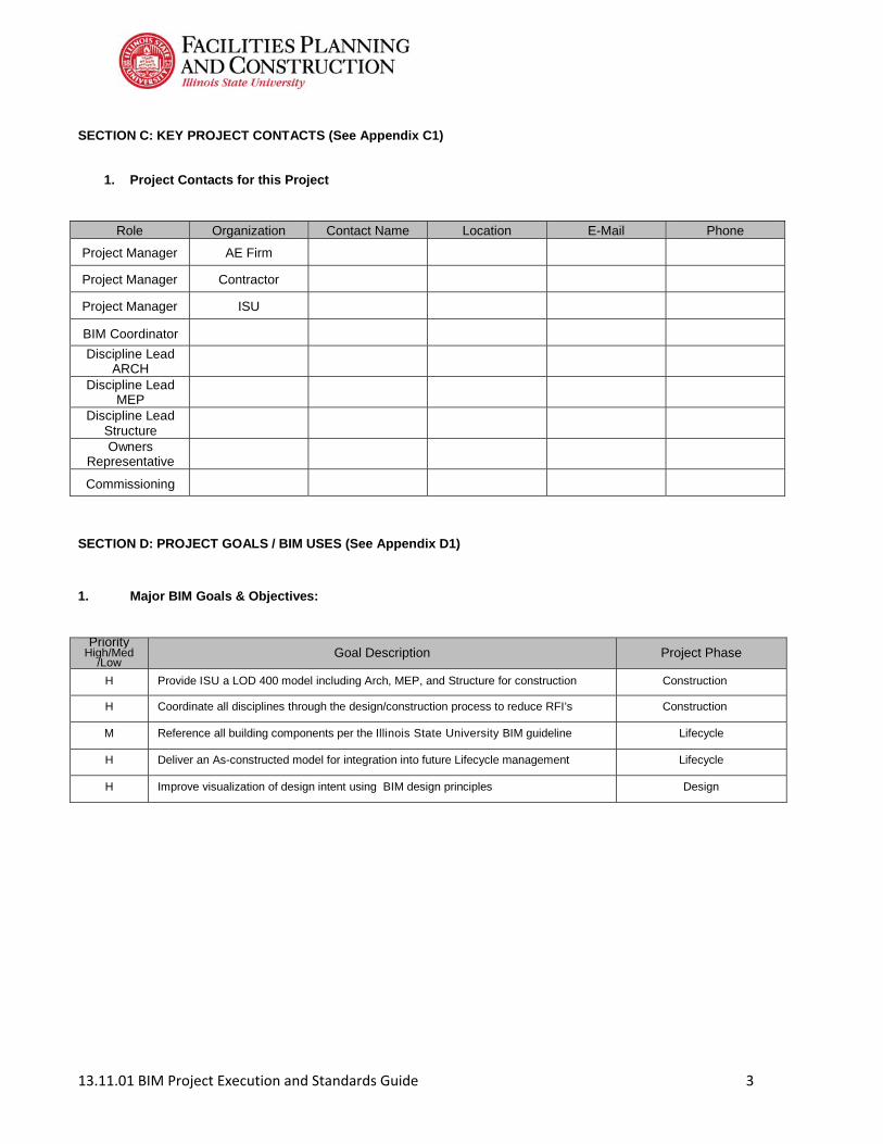
SECTION C: KEY PROJECT CONTACTS (See Appendix C1)
1. Project Contacts for this Project
Role Organization Contact Name Location E-Mail Phone
Project Manager AE Firm
Project Manager Contractor
Project Manager ISU
BIM Coordinator
Discipline Lead ARCH
Discipline Lead MEP
Discipline Lead Structure
Owners Representative
Commissioning
SECTION D: PROJECT GOALS / BIM USES (See Appendix D1) 1. Major BIM Goals & Objectives:
Priority High/Med
/Low Goal Description Project Phase
H Provide ISU a LOD 400 model including Arch, MEP, and Structure for construction Construction
H Coordinate all disciplines through the design/construction process to reduce RFI’s Construction
M Reference all building components per the Illinois State University BIM guideline Lifecycle
H Deliver an As-constructed model for integration into future Lifecycle management Lifecycle
H Improve visualization of design intent using BIM design principles Design

13.11.01 BIM Project Execution and Standards Guide 4
2. Mandatory Uses of BIM Model for this project: (See Appendix D2) X Plan X Design X Construct X Operate
X Programming X Design Authoring Site Utilization Planning X Building Maintenance
Schedule
Site Analysis X Design Reviews X Construction System Building System Analysis
3D Coordination 3D Coordination Asset Management
Structural Analysis Digital Fabrication Space Management/Tracking
Lighting Analysis 3D Control and Planning Disaster Planning
Energy Analysis X Record Modeling Record Modeling
Mechanical Analysis
Sustainability (LEED)
Code Validation
Phase Planning (4D
Modeling)
Phase Planning (4D Modeling)
Phase Planning (4D
Modeling)
Phase Planning (4D Modeling)
X Cost Estimation X Cost Estimating X Cost Estimating Cost Estimating
Project Scope and objectives should determine the proper application of modeling and weigh all factors including time, cost, and effort vs. net benefit. 3. Illinois State University BIM Models for Existing Buildings ISU will make Revit 2013 .rvt model files available for existing buildings that have been modeled. ISU takes no responsibility for the accuracy of these models therefore each should be field verified for accuracy.
SECTION E: BUILDING INFORMATION MODELING FILE TYPES 1. Architectural Models – Autodesk® Revit® Architecture .rvt Models are Revit Architecture project files with Worksets enabled in order to create a central file. The Revit Architecture Model file (.rvt) contains all architectural features for a building including but not limited to:
• Exterior wall systems • Interior wall systems • Fire rated walls • Architectural floor slabs • Roofing systems • Fixed and non-fixed equipment including owner provided equipment • Reflected ceiling plans • Vertical circulation – including elevators, stairs, escalators, and railings • Doors and door frames • Glazing – windows, interior glazing, curtain wall, and storefront • Millwork and casework • Furniture • Finishes – Including all room paint codes, flooring codes, and other finish items • Toilets and accessories • Toilet Partitions Acoustics and sound control systems • Specialties • Minimum BOMA Standards

13.11.01 BIM Project Execution and Standards Guide 5
2. Structural Model – Autodesk® Revit® Structure .rvt Models are Revit Structure project files with Worksets enabled in order to create a central file. The Revit Structure Model file (.rvt) contains all structural features for a building including but not limited to:
• Foundations
• Columns, beams, and joists • Column grid • Brace frames and shear walls • Structural slab • Specialties • Misc. structural components.
3. Mechanical, Electrical, and Plumbing Model – Autodesk® Revit® MEP .rvt Models are Revit MEP project files with Worksets enabled in order to create a central file. The Revit MEP Model file (.rvt) contains all mechanical, electrical, and plumbing features for a building including but not limited to:
• Rain Leader • Overflow drain • Drain • Vent • Waste water • Domestic cold water • Domestic hot water • Steam • Condensate • Hot water • Chilled water • Refrigerants • Relief valves • Fire protection • Gases • Fire alarm system • Mechanical ductwork • Mechanical equipment • Electrical Conduit • Electrical lighting
• Fire/smoke dampers • Valves and valve tags • Plumbing equipment and fixtures • Electrical equipment • Electrical panels and schedules • Metering
• DDC Controls • Telecommunications • Specialties • AV Systems • Fiber Optic Systems • Equipment clearances for replacement, access, service space requirements, gauge reading, valve
clearances, and other operational clearances and access panels.
13.11.01 BIM Project Execution and Standards Guide 6
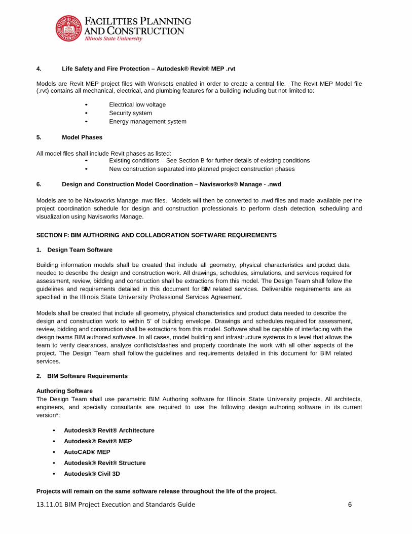
4. Life Safety and Fire Protection – Autodesk® Revit® MEP .rvt Models are Revit MEP project files with Worksets enabled in order to create a central file. The Revit MEP Model file (.rvt) contains all mechanical, electrical, and plumbing features for a building including but not limited to:
• Electrical low voltage • Security system • Energy management system
5. Model Phases
All model files shall include Revit phases as listed:
• Existing conditions – See Section B for further details of existing conditions • New construction separated into planned project construction phases
6. Design and Construction Model Coordination – Navisworks® Manage - .nwd
Models are to be Navisworks Manage .nwc files. Models will then be converted to .nwd files and made available per the project coordination schedule for design and construction professionals to perform clash detection, scheduling and visualization using Navisworks Manage.
SECTION F: BIM AUTHORING AND COLLABORATION SOFTWARE REQUIREMENTS 1. Design Team Software Building information models shall be created that include all geometry, physical characteristics and product data needed to describe the design and construction work. All drawings, schedules, simulations, and services required for assessment, review, bidding and construction shall be extractions from this model. The Design Team shall follow the guidelines and requirements detailed in this document for BIM related services. Deliverable requirements are as specified in the Illinois State University Professional Services Agreement.
Models shall be created that include all geometry, physical characteristics and product data needed to describe the design and construction work to within 5’ of building envelope. Drawings and schedules required for assessment, review, bidding and construction shall be extractions from this model. Software shall be capable of interfacing with the design teams BIM authored software. In all cases, model building and infrastructure systems to a level that allows the team to verify clearances, analyze conflicts/clashes and properly coordinate the work with all other aspects of the project. The Design Team shall follow the guidelines and requirements detailed in this document for BIM related services. 2. BIM Software Requirements Authoring Software The Design Team shall use parametric BIM Authoring software for Illinois State University projects. All architects, engineers, and specialty consultants are required to use the following design authoring software in its current version*:
• Autodesk® Revit® Architecture
• Autodesk® Revit® MEP
• AutoCAD® MEP
• Autodesk® Revit® Structure
• Autodesk® Civil 3D Projects will remain on the same software release throughout the life of the project.

13.11.01 BIM Project Execution and Standards Guide 7
3. Coordination Software
All internal and external model coordination and conflict detection are required to use the following software in its native file format in its current version*:
• Autodesk® Navisworks® Manage
Design Team Coordination Requirements AE Firms are required to perform internal coordination between all necessary disciplines to assure quality project document delivery for all delivery phases.
General Contractor and Construction Manager Coordination Requirements CM/GC Firms are required to coordinate models between disciplines to perform clash detection in order to assure constructability and reduce RFI and change order submissions using Navisworks Manage.
4. Open Architecture for Interoperability The Design Team is encouraged to use products based on or using open architecture for greatest interoperability between consultants and Illinois State University.
5. Project collaboration tools The Design and Construction Team is required to use the Illinois State University designated site, https://sendto.illinoisstate.edu, for all model and document collaboration. Models as well as 2D documentation will be available from this site for download to perform reviews, coordination, estimating, and scheduling. SECTION G: COLLABORATION PROCEDURES 1. Collaboration Strategy: All BIM collaboration will happen using the Illinois State University’s designated site, https://sendto.illinoisstate.edu. Project team members will be required to upload information per the BIM project model and document delivery schedule. 2. BIM Coordination Meeting Procedures: (See Appendix G1)
MEETING TYPE PROJECT STAGE FREQUENCY PARTICIPANTS LOCATION
BIM Requirements Kick-Off
Programming Once ISU/AE/CONST ISU
BIM Execution Plan Demonstration
Programming Once Responsible Party ISU
Design Coordination DD/SD/CD Bi-Weekly Responsible Party ISU
Constructability Coordination
Construction Bi-Weekly Responsible Party ISU

13.11.01 BIM Project Execution and Standards Guide 8
3. Model & Document Delivery Schedule of Information Exchange for Review, Coordination, Submission and Approval: (See Appendix G2)
INFORMATION EXCHNAGE
FILE SENDER
FILE RECEIVER ONE-TIME or FREQUENCY
DUE DATE
or START DATE
MODEL FILE
MODEL SOFTWARE
FILE TYPE
2D FILE TYPE
Design Intent AE Firm https://sendto.illinoisstate.edu
Bi-Weekly ARCH Revit .NWC/ .DWF
MEP Coordination
MEP Consultant
https://sendto.illinoisstate.eduBi-Weekly MEP Revit
.NWC/ .DWF
MEP Coordination
MEP Consultant
https://sendto.illinoisstate.eduBi-Weekly MEP Revit
.NWC/ .DWF
Structure Coordination
Structure Consultant
https://sendto.illinoisstate.eduBi-Weekly STRUC Revit
.NWC/ .DWF
Coordination* GM/GC https://sendto.illinoisstate.edu
Bi-Weekly CONST Navisworks .NWD .PDF
Bid Distribution Construction https://sendto.illinoisstate.edu
Bid Bid CONST Revit .NWC .PDF
Shop Drawings Construction https://sendto.illinoisstate.edu
As Required CONST ARCH Revit .RVT .PDF
Shop Drawings Construction https://sendto.illinoisstate.edu
As Required CONST MEP Revit .RVT
Shop Drawings Construction https://sendto.illinoisstate.edu
As Required CONST STRUC Revit .RVT .PDF
Submittals Construction https://sendto.illinoisstate.edu As Required CONST NA NA .PDF .PDF
* In addition to the BIM model file types, documents will be issued in PDF format. Genneral Contractors and Construction Managers are required to coordinate models between disciplines to perform clash detection in order to reduce RFI and change order submissions using Navisworks Manage. SECTION H: FILE NAMING CONVENTION
1. General
The purpose of this guideline is to provide guidelines and direction for standardizing electronic file information into retrievable formats. Building Information Management Systems require unique file names to function properly and allow searches to find the information the requestor desires. These guidelines/standards will be the first step in developing our Building Information Management Systems (BIM).
This guideline should be followed by all personnel in the Facilities Planning & Construction Department and anyone providing services, documents or work for the University. Deviations from this guideline shall require approval in writing from ISU Facilities Planning & Construction Management Director. This document will be updated regularly as we implement our document consolidation process.
2. File Naming Convention
The following are the new file naming conventions for all files on the Facilities Planning & Construction computer system. The intent of this naming convention is to give each file on our computer network a unique name that can be utilized to retrieve files and information from our computer network.

13.11.01 BIM Project Execution and Standards Guide 9
2.1 File Name Structure & Conventions
To ensure consistent naming for documents, the following file name format needs to be followed. The underscore (_) is used in the file name to separate the section fields. The file names shall consist of five or six distinct sections delineated by the following format:
Field 1_Field 2_Field 3_Field 4_Field 5_Field 6.xxxx
The following table is intended to be a matrix of standard nomenclature to use in the various fields identified.
Table 2.1
3. QUESTIONS
Questions, comments, mistakes that are identified in the use of this process should be directed to ISU Facilities Planning and Construction, attention Interior Design/CAD Manager.
Field 1_Field 2_Field 3_Field 4_Field 5.xxxx
Directory
Field 1
Underscore
Field 2
Underscore
Field 3
Underscore
Field 4
Underscore
Field 5 and/or Field 6
Period
File E
xtension
Date (yy.mm.dd)
Location Sub-
Location Document Type Description
Underscore
Document Revision
13.11.01
Bldg.
Abbrev.
Campus Location
Floor No. Project Name
Admin, Form, Schedule, Scope, Meeting Minutes Bid, RFP, RFQ, Proposal, Budget, Contract Spec Section or Division Shop Drawing, RFI, Photos, O & M, Punchlist System: Structural, Architectural, Mechanical, Electrical, Plumbing, Landscape/Civil, Equipment, Utility, Survey, Telecom, Fire Alarm, Tunnel
Sheet Title or Number
File
Description
Revision
#
Drawing Package (i.e. 50%
CD’s)
Change Order #
RFI #

13.11.01 BIM Project Execution and Standards Guide 10
SECTION I: QUALITY CONTROL
1. Overall Strategy for Quality Control:
The building information modeling process is intended to improve coordination of the design/construction process. Illinois State University requires the following quality control process.
2. Quality Control Checks:
The following checks should be performed to assure quality. Required files/documents will be uploaded to the Illinois State University designated site, https://sendto.illinoisstate.edu per the schedule requirements.
Check Definition Responsible Party Software Program (s) Frequency
Visual Check Review of all 3D design
intent. AE Firm Revit Navisworks Project Review
Visual Check Review of all 2D design
intent. AE Firm PDF/DWF Project Review
Coordination
Coordinate all disciplines including
Arch, MEP, and Structure to reduce
construction RFI’s and change orders
CM/GC Navisworks Manage Project Review
Standards Check Ensure that the BIM and
AEC Standards have been followed.
AE Firm Revit Project Review
Model Integrity Checks
External model coordination should be
performed between disciplines including clash detection and
visualization.
AE Firm Navisworks Manage Project Review
3. Model Accuracy and Tolerances:
Models should include all appropriate dimensioning as needed for design intent, analysis, and construction.
Phase Discipline Tolerance
Design Documents Arch Accurate to +/- 1” of actual size and Location
Shop Drawings Mech Contractor Accurate to +/- 1” of actual size and Location
SECTION J: TECHNOLOGY INFASTRUCTURE REQUIREMENTS
1. Software:
All project participants are required to have the following software in order to participate in the ISU BIM design and construction process. BIM software use is as follows:
BIM Use Discipline (if applicable) Software Version Design Authoring Arch Revit Architecture Current Design Authoring MEP Revit Current Design Authoring Structural Revit Structure Current Design Authoring Civil Civil Current
Coordination Construction Navisworks Manage Current
13.11.01 BIM Project Execution and Standards Guide 11
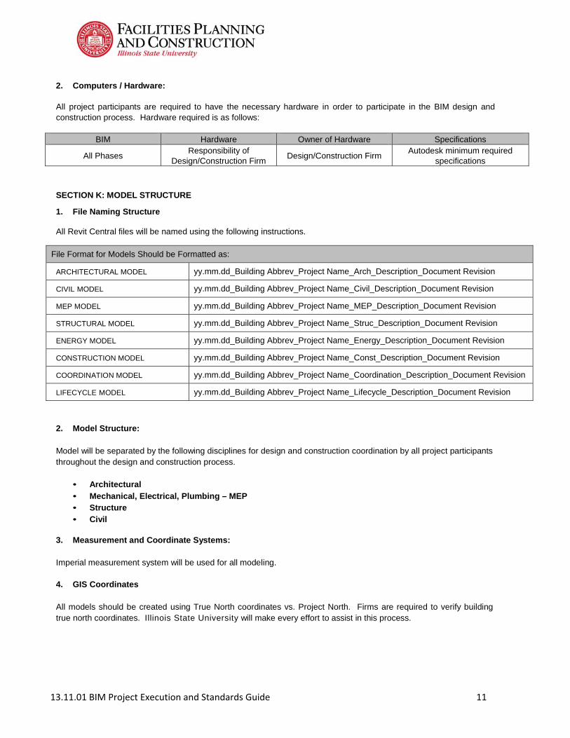
2. Computers / Hardware:
All project participants are required to have the necessary hardware in order to participate in the BIM design and construction process. Hardware required is as follows:
BIM Hardware Owner of Hardware Specifications
All Phases Responsibility of
Design/Construction Firm Design/Construction Firm
Autodesk minimum required specifications
SECTION K: MODEL STRUCTURE
1. File Naming Structure
All Revit Central files will be named using the following instructions.
File Format for Models Should be Formatted as:
ARCHITECTURAL MODEL yy.mm.dd_Building Abbrev_Project Name_Arch_Description_Document Revision
CIVIL MODEL yy.mm.dd_Building Abbrev_Project Name_Civil_Description_Document Revision
MEP MODEL yy.mm.dd_Building Abbrev_Project Name_MEP_Description_Document Revision
STRUCTURAL MODEL yy.mm.dd_Building Abbrev_Project Name_Struc_Description_Document Revision
ENERGY MODEL yy.mm.dd_Building Abbrev_Project Name_Energy_Description_Document Revision
CONSTRUCTION MODEL yy.mm.dd_Building Abbrev_Project Name_Const_Description_Document Revision
COORDINATION MODEL yy.mm.dd_Building Abbrev_Project Name_Coordination_Description_Document Revision
LIFECYCLE MODEL yy.mm.dd_Building Abbrev_Project Name_Lifecycle_Description_Document Revision
2. Model Structure:
Model will be separated by the following disciplines for design and construction coordination by all project participants throughout the design and construction process.
• Architectural
• Mechanical, Electrical, Plumbing – MEP • Structure • Civil
3. Measurement and Coordinate Systems:
Imperial measurement system will be used for all modeling.
4. GIS Coordinates
All models should be created using True North coordinates vs. Project North. Firms are required to verify building true north coordinates. Illinois State University will make every effort to assist in this process.
13.11.01 BIM Project Execution and Standards Guide 12
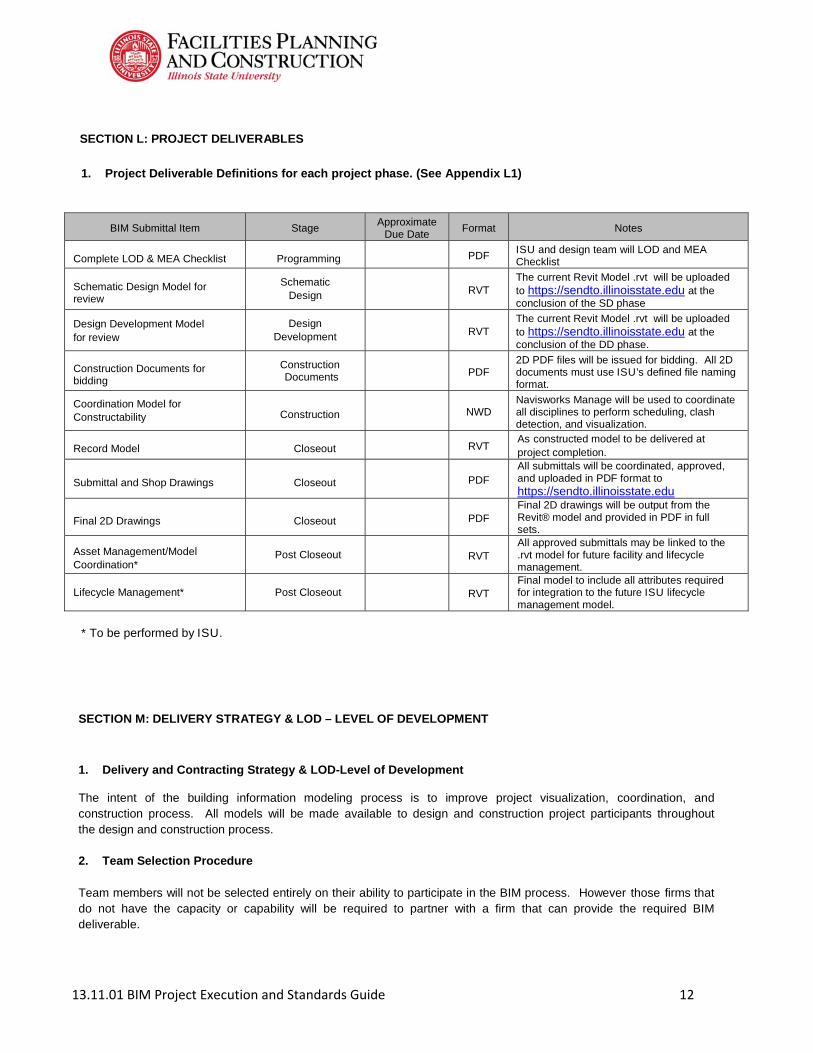
SECTION L: PROJECT DELIVERABLES
1. Project Deliverable Definitions for each project phase. (See Appendix L1)
BIM Submittal Item Stage Approximate
Due Date Format Notes
Complete LOD & MEA Checklist
Programming
ISU and design team will LOD and MEA Checklist
Schematic Design Model for review
Schematic Design
RVT
The current Revit Model .rvt will be uploaded to https://sendto.illinoisstate.edu at the conclusion of the SD phase
Design Development Model for review
Design Development
RVT
The current Revit Model .rvt will be uploaded to https://sendto.illinoisstate.edu at the conclusion of the DD phase.
Construction Documents for bidding
Construction Documents
2D PDF files will be issued for bidding. All 2D documents must use ISU’s defined file naming format.
Coordination Model for Constructability
Construction
NWD
Navisworks Manage will be used to coordinate all disciplines to perform scheduling, clash detection, and visualization.
Record Model
Closeout
RVT
As constructed model to be delivered at project completion.
Submittal and Shop Drawings
Closeout
All submittals will be coordinated, approved, and uploaded in PDF format to https://sendto.illinoisstate.edu
Final 2D Drawings
Closeout
Final 2D drawings will be output from the Revit® model and provided in PDF in full sets.
Asset Management/Model Coordination*
Post Closeout
RVT All approved submittals may be linked to the .rvt model for future facility and lifecycle management.
Lifecycle Management* Post Closeout
RVT Final model to include all attributes required for integration to the future ISU lifecycle management model.
* To be performed by ISU.
SECTION M: DELIVERY STRATEGY & LOD – LEVEL OF DEVELOPMENT
1. Delivery and Contracting Strategy & LOD-Level of Development
The intent of the building information modeling process is to improve project visualization, coordination, and construction process. All models will be made available to design and construction project participants throughout the design and construction process.
2. Team Selection Procedure
Team members will not be selected entirely on their ability to participate in the BIM process. However those firms that do not have the capacity or capability will be required to partner with a firm that can provide the required BIM deliverable.

13.11.01 BIM Project Execution and Standards Guide 13
3. Illinois State University LOD – Level of Development
The following outlines Illinois State University’s definition of Level of Development – LOD for building information model – BIM deliverables. As defined by the AIA document G202-2013.
• LOD 100 – The Model Element may be graphically represented in the Model with a symbol or other
generic representation, but does not satisfy the requirements for LOD 200. Information related to the Model Element (i.e. cost per square foot, tonnage of HVAC, etc.) can be derived from other Model Elements.
• LOD 200 – The Model Element is graphically represented withing the Model as a generic system, object, or
assembly with approximate quantities, size, shape, location, and orientation. Non-graphic information may also be attached to the Model Element.
• LOD 300 – The Model Element is graphically represented within the Model as a specific system, object
or assembly in terms of quantity, shape, location, and orientation. Non-graphic information may also be attached to the Model Element.
• LOD 400 – The Model Element is graphically represented within the Model as a specific system, object or
assembly in terms of size, shape, location, quantity, and orientation with detailing, fabrication, assembly, and installation information. Non-graphic information may also be attached to the Model Element.
• LOD 500 – The Model Element is a field verified representation in terms of size, shape, location, quantity,
and orientation. Non-graphic information may be attached to the Model Elements.
o All as-built record drawings and documentation at the time of turnover must be
provided in Revit. Elements included in the model must be detailed in both the 2D and 3D documentation for internal ISU use. Elements must be clearly marked or tagged and visual in both the 2D and 3D documentation.
o All record drawings must be submitted in AutoCAD DWG, as full set PDF files, and
the Revit RVT file(s)
13.11.01 BIM Project Execution and Standards Guide 14
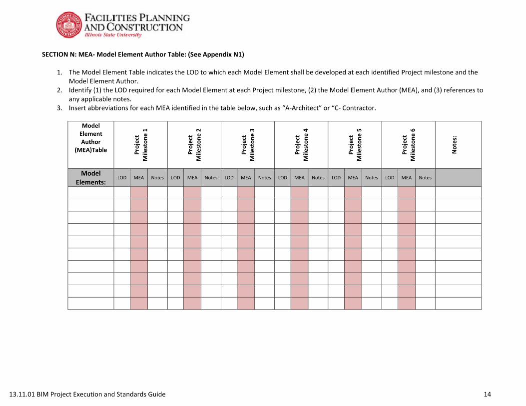
SECTION N: MEA‐ Model Element Author Table: (See Appendix N1)
1. The Model Element Table indicates the LOD to which each Model Element shall be developed at each identified Project milestone and the
Model Element Author. 2. Identify (1) the LOD required for each Model Element at each Project milestone, (2) the Model Element Author (MEA), and (3) references to
any applicable notes. 3. Insert abbreviations for each MEA identified in the table below, such as “A‐Architect” or “C‐ Contractor.
Model Element Author
(MEA)Table Project
Mileston
e 1
Project
Mileston
e 2
Project
Mileston
e 3
Project
Mileston
e 4
Project
Mileston
e 5
Project
Mileston
e 6
Notes:
Model Elements:
LOD MEA Notes LOD MEA Notes LOD MEA Notes LOD MEA Notes LOD MEA Notes LOD MEA Notes
13.11.01 BIM Project Execution and Standards Guide 15
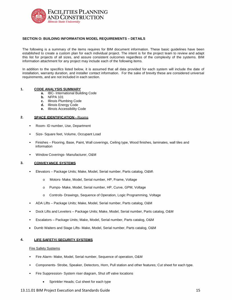
SECTION O: BUILDING INFORMATION MODEL REQUIREMENTS – DETAILS
The following is a summary of the items requires for BIM document information. These basic guidelines have been established to create a custom plan for each individual project. The intent is for the project team to review and adapt this list for projects of all sizes, and assure consistent outcomes regardless of the complexity of the systems. BIM information attachment for any project may include each of the following items.
In addition to the specifics listed below, it is assumed that all data provided for each system will include the date of installation, warranty duration, and installer contact information. For the sake of brevity these are considered universal requirements, and are not included in each section.
1. CODE ANALYSIS SUMMARY
a. IBC- International Building Code b. NFPA 101 c. Illinois Plumbing Code d. Illinois Energy Code e. Illinois Accessibility Code
2. SPACE IDENTIFICATION - Rooms
• Room- ID number, Use, Department
• Size- Square feet, Volume, Occupant Load
• Finishes – Flooring, Base, Paint, Wall coverings, Ceiling type, Wood finishes, laminates, wall tiles and information
• Window Coverings- Manufacturer, O&M
3. CONVEYANCE SYSTEMS
• Elevators – Package Units; Make, Model, Serial number, Parts catalog, O&M\
o Motors- Make, Model, Serial number, HP, Frame, Voltage
o Pumps- Make, Model, Serial number, HP, Curve, GPM, Voltage
o Controls- Drawings, Sequence of Operation, Logic Programming, Voltage
• ADA Lifts – Package Units; Make, Model, Serial number, Parts catalog, O&M
• Dock Lifts and Levelers – Package Units; Make, Model, Serial number, Parts catalog, O&M
• Escalators – Package Units; Make, Model, Serial number, Parts catalog, O&M Dumb Waiters and Stage Lifts- Make, Model, Serial number, Parts catalog, O&M
4. LIFE SAFETY/ SECURITY SYSTEMS
Fire Safety Systems
• Fire Alarm- Make, Model, Serial number, Sequence of operation, O&M
• Components- Strobe, Speaker, Detectors, Horn, Pull station and other features; Cut sheet for each type.
• Fire Suppression- System riser diagram, Shut off valve locations
Sprinkler Heads; Cut sheet for each type
13.11.01 BIM Project Execution and Standards Guide 16
Fire Department Connection Pumps- Make, Model, Serial number, GPM, Pump curve, O&M
Backflow Preventer- Make, Model, O&M
Tamper Prevention- Make, Model, O&M
Security Systems
• Card Access- Component information, Cut sheets or O&M where applicable, each location
• Cameras- Component information, Cut sheets or O&M where applicable, each location
• Motion Sensors- Component information, Cut sheet/O&M where applicable, each location
• Motorized openers- Component information, Cut sheet/O&M where applicable, each location, O&M, Programming and setup information
5. OFFICE/CLASSROOM TECHNOLOGY
Office Technology
o Smart boards- Component information, Cut sheets or O&M where applicable, each location
o Projectors- Component information, Cut sheets or O&M where applicable, each location
o Screens- Component information, Cut sheets or O&M where applicable, each location
o TV/Sound systems- Component information for receivers, speakers amplifiers, DVD, Overhead cameras, Cut sheets or O&M where applicable, each location
Classroom Technology
o Projectors- Component information, Cut sheets or O&M where applicable, each location
o Screens- Component information, Cut sheets or O&M where applicable, each location
o TV/Sound systems- Component information for receivers, speakers amplifiers, DVD,
Overhead cameras, Cut sheets or O&M where applicable, each location
• Multi-System Interaction- Product and System programming files and product information for all interactive carts and podiums designed to merge multiple inputs.
6. INFORMATION TECHNOLOGY SYSTEMS
Unknown Categories– Make, Model, Serial number, Sequence of operation, O&M
7. AIR DISTRIBUTION SYSTEMS
Air Handling Package – Package Air Handling Units; Make, Model, Serial number, Filter size & quantity, Sequence of operation, O&M
• Supply Fans – Make, Model, Serial number, Motor HP, Belt size and quantity, Maximum design flow for
installed system, Fan curve

13.11.01 BIM Project Execution and Standards Guide 17
• Return Fans - Make, Model, Serial number, Motor HP, Belt size and quantity, Maximum design flow for
installed system, Fan curve, Voltage, CFM
Exhaust Fans - Make, Model, Serial number, Belt Size, Bearing number, Sheave numbers, Sequence of operation, O&M
• Motor - Make, Model, Serial number, HP, Frame, Fan curve, Voltage, Efficiency
Outside Air Supply Systems, Heat Recovery Units – Make, Model, Serial number, O&M
• Fans - Make, Model, Serial number, Motor HP, Belt size and quantity, Fan curve, CFM • Motor - Make, Model, Serial number, HP, Frame, Voltage
Emergency Fire System AHU Interaction –Make, Model, Serial number, Sequence of operation, Graphical system riser representation, Smoke & heat detector data
• Smoke Purge Fan- Make, Model, Serial number, fan curve, Belts size and quantity • Fire Dampers- Make, model and motor information at each location
8. BUILDING AUTOMATION, MONITORING, SPACE CONTROL
• Thermostat, Humidity and remote Sensors- Make, Model, Serial number, Unit(s) controlled, Spaces controlled at each location, Signal amperage/voltage
• Remote Static pressure sensors- Make, Model, Serial number, Unit(s) controlled, Sequence of
operation or space/equipment controlled, at each location, Signal amperage/voltage Differential Pressure Sensors- Make, Model, Serial number, Units(s) controlled, Sequence of
operation or equipment controlled at each location, serial amperage/voltage 9. HEATING FUNCTIONS
Steam Delivery and Condensate Return
• Meters, Gauges
Relief Valves
Pressure Valves
Coils- Make, Model, Serial number, Sequence of Operation, O&M, Size, materials, Capacity, Pressure drop, Operating Pressure, Maximum design conditions including Steam Consumption, Air flow, Air inlet temperature and Air outlet temperature.
• Pumping traps, Receivers- Make, Model, Serial number, Sequence of Operation, O&M, Capacity
• Spence type PRV’s- Make, Model, Serial number, Sequence of Operation, O&M, Entering pressure,
Discharge pressure, Capacity
Heating Water Distribution
• Pumps- Make, Model, Serial number, Sequence of operation, Pump curve, O&M, Horsepower, Voltage, GPM

13.11.01 BIM Project Execution and Standards Guide 18
• Heat Exchangers- Make, Model, Serial number, Sequence of operation, Pump curve, O&M, Operating
Pressure, Maximum design conditions including Steam Consumption, Air flow, Air inlet temperature and Air outlet temperature.
• Fin Tubes and Radiant Panels- Make, Model, Serial number, Sequence of operation, Pump curve,
O&M, Maximum steam consumption.
Cabinet and/or Suspended Unit Heaters
• Unit Heaters- Make, Model, Serial number, BTU’s, Sequence of operation, O&M, CFM, GPM
• Cabinet Unit Heaters- Make, Model, Serial number, BTUs, Sequence of operation, O&M, CFM, GPM
• Gas fired units - Make, Model, Serial number, Sequence of operation, O&M, CFM, BTUs
• Remote sensors - Make, Model, Serial number, O&M, Signal Amperage
10. COOLING FUNCTIONS
Chillers and Refrigeration Systems – Make, Model, Serial number, Unit(s), Spaces controlled, at each location, Steam Absorption Units, Electric Chillers, Size, Voltage, Capacity, Efficiency, etc.
• Cooling Towers- Condenser Motors, Fan Motors, Variable speed drives, Sumps, Drains, Condition Direct
Expansion Refrigeration, Design capacity and maximum design conditions, DX Circuits, Motor Voltage and HP, Efficiency
• Condenser Water Pumps- Make, Model, Serial Number, Sequence of Operation, Pump Curve with Design
Operation, O&M Hyperlink, HP, Voltage, GPM Chilled water pumps- Make, Model, Serial number, Sequence of Operation, Pump Curve with design
operation, O&M Hyperlink, HP, Voltage, GPM, Variable Speed Drive data.
• Split Systems and Package (Leibert type) AC Units- Make, Model, Serial number, Capacity in
BTU, O&M Hyperlink, System efficiency, Voltage, Refigerant.
o Sensors- Make, Model, Serial number, Sequence of Operation, O&M
o Condensation pumps - Make, Model, Serial number, O&M 11. PLUMBING SYSTEMS
Chilled Water Plumbing
• Meters- Make, Model, Serial number, Sequence of Operation, O&M
• Back flow Preventers- Make, Model, Serial number, Sequence of Operation, Certification, O&M
• Booster/Circulation Pumps- Make, Model, Serial number, Design Criteria, Sequence of Operation, O&M, Capacity, Operating pressures.
• Water Softeners- Make, Model, Serial number, Sequence of operation, O&M, Capacity.
• Heaters and Heat Exchangers- Make, Model, Serial number, O&M
• Pressure Relief Valves- Make, Model, Cut sheets each location, O&M, Capacity, Operating pressures.
• Expansion Tanks- Make, Model, Cut sheets, Capacity.
13.11.01 BIM Project Execution and Standards Guide 19
Fire Protection Plumbing
• Meters- Make, Model, Serial number, Sequence of Operation, O&M
• Back flow Preventers- Make, Model, Serial number, Sequence of Operation, Certification, O&M
• Booster/Circulation Pumps- Make, Model, Serial number, Design Criteria, Sequence of Operation, O&M, Capacity, Operating pressures.
• Water Softeners- Make, Model, Serial number, Sequence of operation, O&M, Capacity.
• Heaters and Heat Exchangers- Make, Model, Serial number, O&M
• Pressure Relief Valves- Make, Model, Cut sheets each location, O&M, Capacity, Operating pressures.
• Expansion Tanks- Make, Model, Cut sheets, Capacity. Sanitary System
• Sump Pumps- Make, Model, Serial number, Sequence of operation, Pump curve, O&M
• Acid Treatment- Component information
• Manholes- Component information, Cut sheets each location
Storm System
• Roof Sumps - Component information, Cut sheets where applicable, each location
• Sump pumps- Make, Model, Serial number, Sequence of operation, Pump curve, O&M
12. ARCHITECTURAL
Building Envelope Systems
• Roof System- Manufacturer, Type and Material information, Green Roof Details
• Exterior Doors- Make, Model, Glass details, Revolving/Motorized details, Sealant, Hardware
• Windows- Make, Model, Reflection, Color, Grade, Sealant, Hardware
• Skylights- Make, Model, Reflection, Color, Grade, Sealant
• Access Doors and Hatches, Ladders- Make, Model
13. BUILDING COMPRESSED GAS SYSTEMS
Natural Gas System- Meters, Regulators/PRV’s, Safeties Make, Model, Mfr. Information, Size, Capacity, Operating pressure.
Compressed Air Systems
• Air Compressors- Make, Model, Mfr. Information, Capacity, Voltage, Pressure
• Air Dryers- Make, Model, Serial number, Sequence of Operation, O&M, Capacity, Mfr. Information
13.11.01 BIM Project Execution and Standards Guide 20
• Storage tanks- Make, Model, Serial number, Mfr. Information, Size
Lab Gas Systems
• Regulator stations- Make, Model, Mfr. Information, O&M
• Monitoring and Alarm Systems- Make, Model, Serial number, Mfr. Information, O&M
• Vacuum Pumps- Make, Model, Serial number, O&M, Mfr. Information
14. ELECTRICAL
Electrical Distribution System
• Transformers- Make, Model, Serial number, Mfr. Information, O&M, Voltage, Size
• Switch Gear- Make, Model, Serial number, Mfr. Information, O&M
• Panels- Make, Model, Mfr. Information, O&M, Voltage, Size
• Major Equipment Service Disconnects- Make, Model, Mfr. Information Provide arc flash information
Emergency Electric Generation
• Service Entrance- Make, Model, Serial number, Mfr. Information, O&M
• Emergency Generators- Make, Model, Serial number, O&M, Parts list, Service History
• Transfer Switches- Make, Model, Serial number, Mfr. Information, O&M
• Emergency Lighting Components- Make, Model, Serial number, Mfr. Information, O&M Lighting
Provide arc flash information
Systems
• Fixtures- Make, Model, Bulb type and quantity, Mfr. Information
• Controls- Make, Model, Serial number, Mfr. Information, O&M
• Occupancy Sensors- Make, Model, Serial number, Mfr. Information, O&M
• Timers- Make, Model, Serial number, Mfr. Information, O&M Specialty Lighting- Make, Model, Serial number, Mfr. Information, O&M


![BIM PROJECT EXECUTION PLAN · 2019-05-06 · [PROJECT TITLE] [DATE] BUILDING INFORMATION MODELING PROJECT EXECUTION PLAN VERSION 2.0 1 SECTION A: BIM PROJECT EXECUTION PLAN OVERVIEW](https://static.documents.pub/doc/80x56/5e6a54266da473305d796145/bim-project-execution-plan-2019-05-06-project-title-date-building-information.jpg)
![BIM PROJECT EXECUTION PLAN - cdn.ymaws.com · [PROJECT TITLE] [DATE] BUILDING INFORMATION MODELING PROJECT EXECUTION PLAN VERSION 1.05 1 SECTION A: BIM PROJECT EXECUTION PLAN OVERVIEW](https://static.documents.pub/doc/80x56/5d4d572388c993dd728bc195/bim-project-execution-plan-cdnymawscom-project-title-date-building-information.jpg)


