Mineral sands is a term used to refer todeposits of heavy minerals such as ilmenite,zircon, rutile, leucoxene, and monazite. Thesesands originate from igneous rocks, such asgranite and basalt, which have weathered torelease the heavy minerals. Mineral sandsdeposits are usually found in strands along oldcoastal regions where weathering and erosionhave separated the heavier minerals from thelighter minerals and have formed concentratedorebodies. Australia, South Africa, the USA,Canada, and India are the principal producersof mineral sands. The Richards Bay reserves inSouth Africa are among the largest in theworld.
Mineral sands are used as a source oftitanium minerals. The most importantnaturally occurring titanium minerals areilmenite, rutile, and leucoxene. These mineralsare mined to produce titanium dioxide (TiO2)feedstock for pigment manufacturers. Theminerals are used as feedstock either in theirnatural form or in an upgraded form, such assynthetic rutile and titania slag, which areproduced through the secondary processing ofilmenite.
TiO2 feedstock is predominantly used toproduce pigments, titanium metal, weldingfluxes, and other specialized products. About95% of titanium dioxide feedstocks are used inthe production of titanium dioxide pigments,which are widely used in paints, paper, andplastics. TiO2 pigment is extremely refractive,
and adds brightness, whiteness, and opacity toproducts. Because of its unique ‘hiding power’and non-toxicity, it is a major ingredient in themanufacturing of paint, plastic, papers, andinks. It is also widely used in food products,sunscreens, and other cosmetics.
The three South African based producersof TiO2 feedstock—Richards Bay Minerals,Namakwa Sands, and Ticor South Africa, allproduce TiO2 slag via the smelting of ilmenite.The whole industry—from mining of heavymineral deposits through to pigment manufac-turing—is highly competitive, with littlesharing of metallurgical process or marketinginformation among companies.
The origin of Ticor SA
In 1995, Iscor Mining (now Kumba Resources)initiated the detailed feasibility study for theIHM Heavy Minerals Project. The feasibilitystudy formed the basis for a detailedengineering and design phase, whichcommenced in November 1996. This continuedinto 2000, when the Iscor Board approved theimplementation of Phase 1 of the Project—Hillendale mine and the Mineral SeparationPlant. Construction of the Smelters—Phase 2—was subsequently announced on 15 August2001.
During February 2001, Ticor Ltd, anAustralian publicly listed company, acquired40% of the IHM Heavy Minerals Project,together with management control. Hence thechange of name to Ticor South Africa. By2005, the TiO2 feedstock production underTicor’s management control was over 11% ofthe world’s feedstock production, therebyestablishing Ticor as one of the industry
Ilmenite smelting at Ticor SAby H. Kotzé*, D. Bessinger†, and J. Beukes*
Synopsis
Ticor SA began with a detailed feasibility study in 1995. TheHillendale mine (situated between Richards Bay and Empangeni)and mineral separation plant were approved in 2000. The smelter,just outside Empangeni, consists of two 36 MW DC arc furnaces thatwere commissioned in 2003. Experiences gained during the initialcommissioning of the furnaces proved valuable in later commis-sioning work, as shown by the increase in ramp-up rates. Thecapacity of the plant is 250 kt/a TiO2 slag and 145 kt/a of pig iron.
Metallurgy, 2006. SA ISSN 0038–223X/3.00 +0.00. This paper was first published at the SAIMMConference, The South African Pyrometallurgy2006 International Conference, Mar. 2006
165The Journal of The South African Institute of Mining and Metallurgy VOLUME 106 NON-REFEREED PAPER MARCH 2006 ▲
Ilmenite smelting at Ticor SA
leaders. During October 2005, minority shareholders in TicorLtd accepted a proposal from Kumba Resources Ltd, to re-acquire shares in, and management control of, Ticor (byimplication also of Ticor SA).
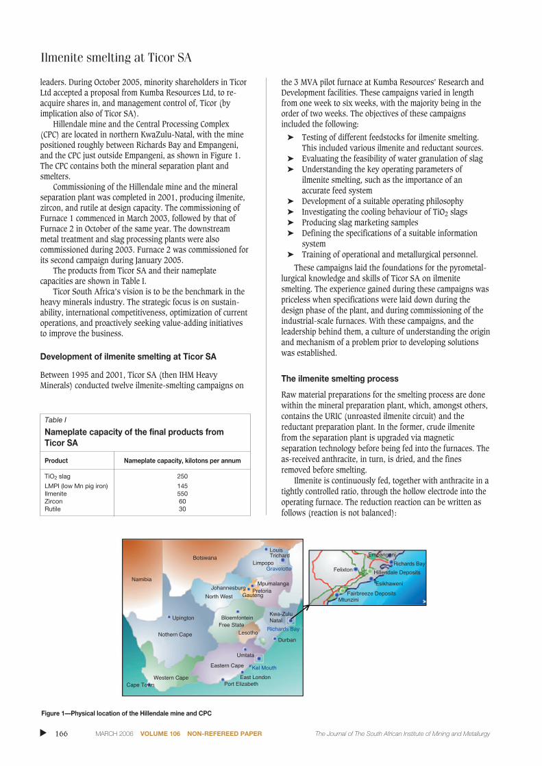
Hillendale mine and the Central Processing Complex(CPC) are located in northern KwaZulu-Natal, with the minepositioned roughly between Richards Bay and Empangeni,and the CPC just outside Empangeni, as shown in Figure 1.The CPC contains both the mineral separation plant andsmelters.
Commissioning of the Hillendale mine and the mineralseparation plant was completed in 2001, producing ilmenite,zircon, and rutile at design capacity. The commissioning ofFurnace 1 commenced in March 2003, followed by that ofFurnace 2 in October of the same year. The downstreammetal treatment and slag processing plants were alsocommissioned during 2003. Furnace 2 was commissioned forits second campaign during January 2005.
The products from Ticor SA and their nameplatecapacities are shown in Table I.
Ticor South Africa’s vision is to be the benchmark in theheavy minerals industry. The strategic focus is on sustain-ability, international competitiveness, optimization of currentoperations, and proactively seeking value-adding initiativesto improve the business.
Development of ilmenite smelting at Ticor SA
Between 1995 and 2001, Ticor SA (then IHM HeavyMinerals) conducted twelve ilmenite-smelting campaigns on
the 3 MVA pilot furnace at Kumba Resources’ Research andDevelopment facilities. These campaigns varied in lengthfrom one week to six weeks, with the majority being in theorder of two weeks. The objectives of these campaignsincluded the following:
➤ Testing of different feedstocks for ilmenite smelting.This included various ilmenite and reductant sources.
➤ Evaluating the feasibility of water granulation of slag➤ Understanding the key operating parameters of
ilmenite smelting, such as the importance of anaccurate feed system
➤ Development of a suitable operating philosophy➤ Investigating the cooling behaviour of TiO2 slags➤ Producing slag marketing samples➤ Defining the specifications of a suitable information
system➤ Training of operational and metallurgical personnel.
These campaigns laid the foundations for the pyrometal-lurgical knowledge and skills of Ticor SA on ilmenitesmelting. The experience gained during these campaigns waspriceless when specifications were laid down during thedesign phase of the plant, and during commissioning of theindustrial-scale furnaces. With these campaigns, and theleadership behind them, a culture of understanding the originand mechanism of a problem prior to developing solutionswas established.
The ilmenite smelting process
Raw material preparations for the smelting process are donewithin the mineral preparation plant, which, amongst others,contains the URIC (unroasted ilmenite circuit) and thereductant preparation plant. In the former, crude ilmenitefrom the separation plant is upgraded via magneticseparation technology before being fed into the furnaces. Theas-received anthracite, in turn, is dried, and the finesremoved before smelting.
Ilmenite is continuously fed, together with anthracite in atightly controlled ratio, through the hollow electrode into theoperating furnace. The reduction reaction can be written asfollows (reaction is not balanced):
▲
166 MARCH 2006 VOLUME 106 NON-REFEREED PAPER The Journal of The South African Institute of Mining and Metallurgy
Figure 1—Physical location of the Hillendale mine and CPC
Table I
Nameplate capacity of the final products from Ticor SA
The slag (written as M3O5) contains titanium in both the+3 and +4 oxidation states. The resultant slag has a lowerdensity than the iron, and separation of the two liquidproducts occurs within the furnace.
The primary product—titanium oxide slag—contains anaverage of 85% TiO2. (Total Ti is expressed as TiO2, as Ti inthe slag is present in both the +3 and +4 oxidation states.) Inaddition, the slag also contains approximately 10% FeO. Alsopresent are impurities such as SiO2, Al2O3, MgO, MnO, CaO,Cr2O3, V2O5, and ZrO2. Due to the reducing conditions inilmenite smelting, some of the impurities (such as MnO) arepartially reduced, and report also to the metal phase. Themaximum limits for impurities in both the slag and iron arefixed by contractual agreements between supplier andcustomer.
The smelting and reduction processes are conductedwithin a crucible of solidified, high titanium content slag(known as the freeze lining), contained within the furnacerefractory walls. This freeze lining protects the magnesiarefractory from chemical slag attack. Apart from increasingthe MgO content of the slag, and thereby exceeding themaximum impurity specification, chemical attack by the slagon the magnesia bricks reduces the life of the refractorylining. A worst-case scenario would be chemical erosionthrough the thickness of the lining, leading to a side-wallbreakthrough. Protecting the integrity of the freeze lining,through firm control over the mass and energy balancewithin the process, is therefore one of the primary objectivesof ilmenite smelting.
Slag and iron are tapped periodically from separate setsof tapholes located around the circumference of the furnace.The slag tapholes are on a higher elevation than those foriron. Slag is tapped into 20 t steel pots, and cooled for severalhours within these pots before the slag blocks are tipped out.These blocks are subsequently transported to the blockyardwhere they are cooled under water sprays for a number ofdays. They are then crushed, milled, and separated accordingto size fractions, as required by the pigment manufacturers.
The tapped pig iron is recarburized and desulphurized,and cast into 7 kg pigs for use in (amongst others) theautomotive industry.
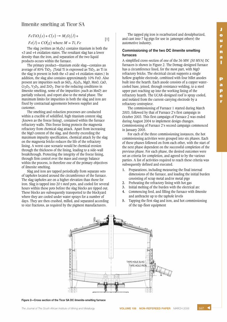
Commissioning of the two DC ilmenite smeltingfurnacesA simplified cross-section of one of the 36 MW (50 MVA) DCfurnaces is shown in Figure 2. The Demag-designed furnacehas a circumference lined, for the most part, with MgOrefractory bricks. The electrical circuit supports a singlehollow graphite electrode, combined with four billet anodesbuilt into the hearth. Each anode consists of a copper water-cooled base, joined, through resistance welding, to a steelupper part reaching up into the working lining of therefractory hearth. The UCAR-designed roof is spray cooled,and isolated from the current-carrying electrode by arefractory centrepiece.
The commissioning of Furnace 1 started during March2003, followed by that of Furnace 2’s first campaign inOctober 2003. This first campaign of Furnace 2 was endedduring August 2004 to implement design changes.Commissioning of Furnace 2’s second campaign commencedin January 2005.
For each of the three commissioning instances, the hotcommissioning activities were grouped into six phases. Eachof these phases followed on from each other, with the start ofthe next phase dependent on the successful completion of theprevious phase. For each phase, the desired outcomes wereset as criteria for completion, and agreed to by the variousparties. A list of activities required to reach these criteria wassubsequently defined and executed.
1. Preparations, including measuring the final internaldimensions of the furnace, and loading the initial burdenconsisting of scrap metal and/or metal pigs
2. Preheating the refractory lining with hot gas3. Initial melting of the burden with the electrical arc4. Commencing feed, and filling the furnace with ilmenite
and anthracite up to the taphole levels5. Tapping the first slag and iron, and hot commissioning
of the tap-floor equipment
FeTiO s C s M O 1
Fe 1 CO g M Ti,Fe
3 3 5
where
( ) + ( ) → ( ) +
( ) + ( ) =
Ilmenite smelting at Ticor SAJournal
Paper
167The Journal of The South African Institute of Mining and Metallurgy VOLUME 106 NON-REFEREED PAPER MARCH 2006 ▲
Figure 2—Cross section of the Ticor SA DC ilmenite-smelting furnace
TAPE HOLE SLAG
TAPE HOLE IRON
Ilmenite smelting at Ticor SA
6. Stabilizing the process, and ramping up feed rates andproduction activities.
Many of the initial criteria were based on experience fromthe pilot plant campaigns at the Kumba Research facilities.As per the nature of commissioning, new challengespresented more learning opportunities, which were workedinto the criteria of subsequent commissioning programmes.Some of these interesting learning opportunities aredescribed below.
Gas preheating of the refractory liningTo enable gas preheating, several burners were positionedthrough the furnace roof, and fired with Sasol gas and air.The gas volume and air ratio were controlled using thermo-couples installed through the roof, protruding downwardsinto the furnace freeboard. The Sasol gas used was methanerich, yielding the following combustion reaction:
[2]
Hence, when water dripping from the off-gas duct ofFurnace 1 was detected during the Furnace 1 refractorypreheat of December 2002, it was initially thought that thecause was water originating from the combustion of Sasolgas. However, on further investigation, the volume of wateroriginating from this source proved too little to be the solesource. Incorporating the high air volumes used, the highhumidity, and ambient temperatures during Decembermonths in KwaZulu-Natal into the combustion environment,pointed to the source of the water: as the gas volumes areincreased to reach higher preheating temperatures, the watervolume blown as vapour into the furnace increased, while theinternal furnace pressure increased. As these gases werecondensed and cooled when passing out of the furnace intothe off-gas duct, conditions favoured condensation of wateronto the water-cooled off-gas duct. This water flowed directlyback into the furnace, damaging sidewall and hearth refrac-tories.
The hydration damage to the magnesia bricks wasextensive, and necessitated a complete refractory rebuild ofFurnace 1. During the subsequent commissioning periods ofFurnace 1, and both commissioning campaigns of Furnace 2,the following control actions were implemented:
➤ A temporary exhaust duct was installed on aninspection hole in the roof, and used to ventcombustion gas during the initial hours of preheating.Following a short upward portion, this duct wasdirected downwards, preventing any condensationfrom flowing back into the furnace. During this periodthe off-gas duct was blanked off at the upper end.
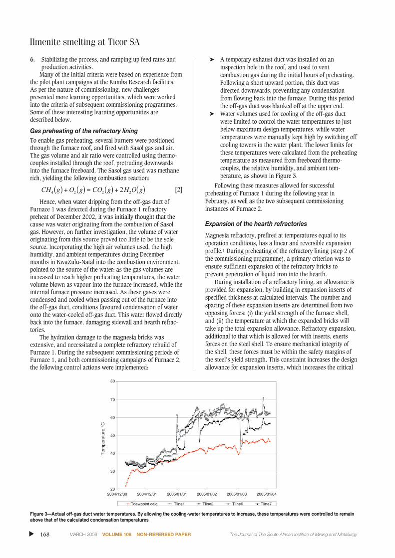
➤ Water volumes used for cooling of the off-gas ductwere limited to control the water temperatures to justbelow maximum design temperatures, while watertemperatures were manually kept high by switching offcooling towers in the water plant. The lower limits forthese temperatures were calculated from the preheatingtemperature as measured from freeboard thermo-couples, the relative humidity, and ambient tem-perature, as shown in Figure 3.
Following these measures allowed for successfulpreheating of Furnace 1 during the following year inFebruary, as well as the two subsequent commissioninginstances of Furnace 2.
Expansion of the hearth refractories
Magnesia refractory, prefired at temperatures equal to itsoperation conditions, has a linear and reversible expansionprofile.1 During preheating of the refractory lining (step 2 ofthe commissioning programme), a primary criterion was toensure sufficient expansion of the refractory bricks toprevent penetration of liquid iron into the hearth.
During installation of a refractory lining, an allowance isprovided for expansion, by building in expansion inserts ofspecified thickness at calculated intervals. The number andspacing of these expansion inserts are determined from twoopposing forces: (i) the yield strength of the furnace shell,and (ii) the temperature at which the expanded bricks willtake up the total expansion allowance. Refractory expansion,additional to that which is allowed for with inserts, exertsforces on the steel shell. To ensure mechanical integrity ofthe shell, these forces must be within the safety margins ofthe steel’s yield strength. This constraint increases the designallowance for expansion inserts, which increases the critical
CH g O g CO g H O g4 2 2 22( ) + ( ) = ( ) + ( )
▲
168 MARCH 2006 VOLUME 106 NON-REFEREED PAPER The Journal of The South African Institute of Mining and Metallurgy
Figure 3—Actual off-gas duct water temperatures. By allowing the cooling-water temperatures to increase, these temperatures were controlled to remainabove that of the calculated condensation temperatures
temperature at which joints between bricks will close upfully. Reaching this ‘critical temperature’ during thepreheating stage proved to be a challenge with each commis-sioning instance.
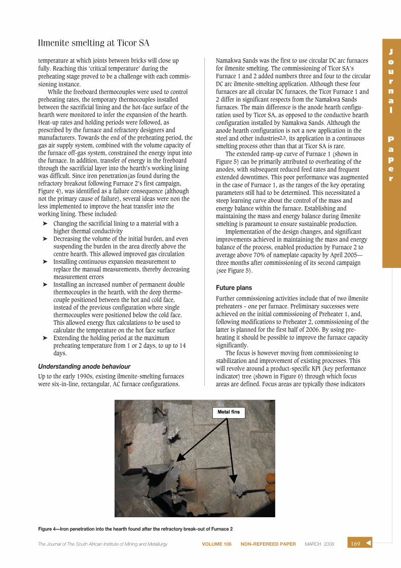
While the freeboard thermocouples were used to controlpreheating rates, the temporary thermocouples installedbetween the sacrificial lining and the hot-face surface of thehearth were monitored to infer the expansion of the hearth.Heat-up rates and holding periods were followed, asprescribed by the furnace and refractory designers andmanufacturers. Towards the end of the preheating period, thegas air supply system, combined with the volume capacity ofthe furnace off-gas system, constrained the energy input intothe furnace. In addition, transfer of energy in the freeboardthrough the sacrificial layer into the hearth’s working liningwas difficult. Since iron penetration(as found during therefractory breakout following Furnace 2’s first campaign,Figure 4), was identified as a failure consequence (althoughnot the primary cause of failure), several ideas were non theless implemented to improve the heat transfer into theworking lining. These included:
➤ Changing the sacrificial lining to a material with ahigher thermal conductivity
➤ Decreasing the volume of the initial burden, and evensuspending the burden in the area directly above thecentre hearth. This allowed improved gas circulation
➤ Installing an increased number of permanent doublethermocouples in the hearth, with the deep thermo-couple positioned between the hot and cold face,instead of the previous configuration where singlethermocouples were positioned below the cold face.This allowed energy flux calculations to be used tocalculate the temperature on the hot face surface
➤ Extending the holding period at the maximumpreheating temperature from 1 or 2 days, to up to 14days.
Understanding anode behaviourUp to the early 1990s, existing ilmenite-smelting furnaceswere six-in-line, rectangular, AC furnace configurations.
Namakwa Sands was the first to use circular DC arc furnacesfor ilmenite smelting. The commissioning of Ticor SA’sFurnace 1 and 2 added numbers three and four to the circularDC arc ilmenite-smelting application. Although these fourfurnaces are all circular DC furnaces, the Ticor Furnace 1 and2 differ in significant respects from the Namakwa Sandsfurnaces. The main difference is the anode hearth configu-ration used by Ticor SA, as opposed to the conductive hearthconfiguration installed by Namakwa Sands. Although theanode hearth configuration is not a new application in thesteel and other industries2,3, its application in a continuoussmelting process other than that at Ticor SA is rare.
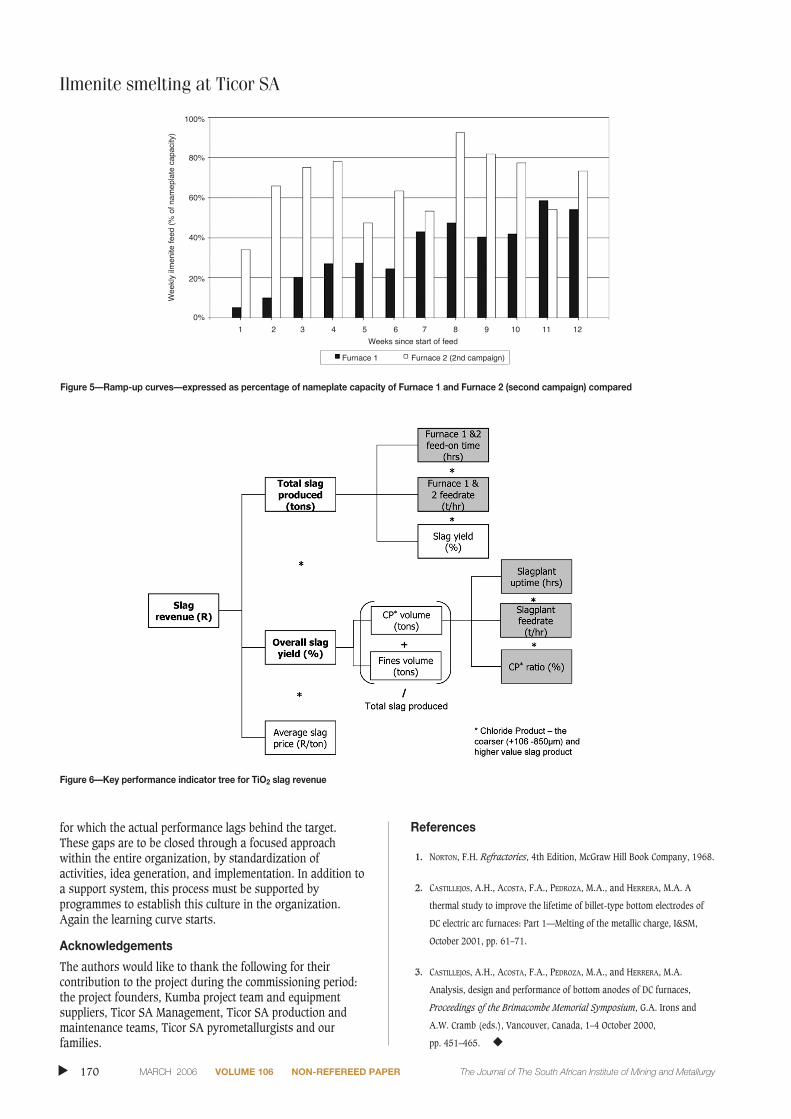
The extended ramp-up curve of Furnace 1 (shown inFigure 5) can be primarily attributed to overheating of theanodes, with subsequent reduced feed rates and frequentextended downtimes. This poor performance was augmentedin the case of Furnace 1, as the ranges of the key operatingparameters still had to be determined. This necessitated asteep learning curve about the control of the mass andenergy balance within the furnace. Establishing andmaintaining the mass and energy balance during ilmenitesmelting is paramount to ensure sustainable production.
Implementation of the design changes, and significantimprovements achieved in maintaining the mass and energybalance of the process, enabled production by Furnace 2 toaverage above 70% of nameplate capacity by April 2005—three months after commissioning of its second campaign(see Figure 5).
Future plans
Further commissioning activities include that of two ilmenitepreheaters – one per furnace. Preliminary successes wereachieved on the initial commissioning of Preheater 1, and,following modifications to Preheater 2, commissioning of thelatter is planned for the first half of 2006. By using pre-heating it should be possible to improve the furnace capacitysignificantly.
The focus is however moving from commissioning tostabilization and improvement of existing processes. Thiswill revolve around a product-specific KPI (key performanceindicator) tree (shown in Figure 6) through which focusareas are defined. Focus areas are typically those indicators
Ilmenite smelting at Ticor SAJournal
Paper
The Journal of The South African Institute of Mining and Metallurgy VOLUME 106 NON-REFEREED PAPER MARCH 2006 169 ▲
Figure 4—Iron penetration into the hearth found after the refractory break-out of Furnace 2
Ilmenite smelting at Ticor SA
for which the actual performance lags behind the target.These gaps are to be closed through a focused approachwithin the entire organization, by standardization ofactivities, idea generation, and implementation. In addition toa support system, this process must be supported byprogrammes to establish this culture in the organization.Again the learning curve starts.
Acknowledgements
The authors would like to thank the following for theircontribution to the project during the commissioning period:the project founders, Kumba project team and equipmentsuppliers, Ticor SA Management, Ticor SA production andmaintenance teams, Ticor SA pyrometallurgists and ourfamilies.
References
1. NORTON, F.H. Refractories, 4th Edition, McGraw Hill Book Company, 1968.
2. CASTILLEJOS, A.H., ACOSTA, F.A., PEDROZA, M.A., and HERRERA, M.A. A
thermal study to improve the lifetime of billet-type bottom electrodes of
DC electric arc furnaces: Part 1—Melting of the metallic charge, I&SM,
October 2001, pp. 61–71.
3. CASTILLEJOS, A.H., ACOSTA, F.A., PEDROZA, M.A., and HERRERA, M.A.
Analysis, design and performance of bottom anodes of DC furnaces,
Proceedings of the Brimacombe Memorial Symposium, G.A. Irons and
A.W. Cramb (eds.), Vancouver, Canada, 1–4 October 2000,
pp. 451–465. ◆
▲
170 MARCH 2006 VOLUME 106 NON-REFEREED PAPER The Journal of The South African Institute of Mining and Metallurgy
Figure 5—Ramp-up curves—expressed as percentage of nameplate capacity of Furnace 1 and Furnace 2 (second campaign) compared
Figure 6—Key performance indicator tree for TiO2 slag revenue