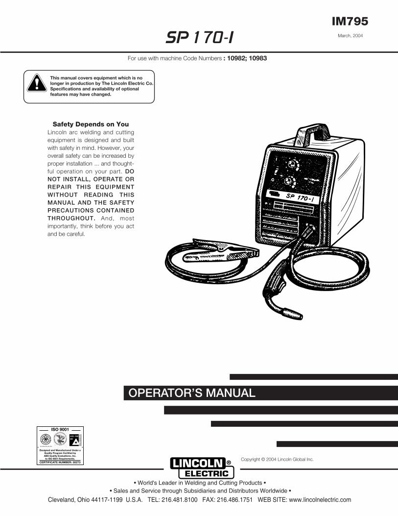
Safety Depends on YouLincoln arc welding and cuttingequipment is designed and builtwith safety in mind. However, youroverall safety can be increased byproper installation ... and thought-ful operation on your part. DONOT INSTALL, OPERATE ORREPAIR THIS EQUIPMENTWITHOUT READING THISMANUAL AND THE SAFETYPRECAUTIONS CONTAINEDTHROUGHOUT. And, mostimportantly, think before you actand be careful.
For use with machine Code Numbers : 10982; 10983
• Sales and Service through Subsidiaries and Distributors Worldwide •
This manual covers equipment which is no longer in production by The Lincoln Electric Co. Speci�cations and availability of optional features may have changed.
FOR ENGINEpowered equipment.
1.a. Turn the engine off before troubleshooting and maintenancework unless the maintenance work requires it to be running.
____________________________________________________1.b. Operate engines in open, well-ventilated
areas or vent the engine exhaust fumes outdoors.
____________________________________________________1.c. Do not add the fuel near an open flame
welding arc or when the engine is running.Stop the engine and allow it to cool beforerefueling to prevent spilled fuel from vaporiz-ing on contact with hot engine parts andigniting. Do not spill fuel when filling tank. Iffuel is spilled, wipe it up and do not startengine until fumes have been eliminated.
____________________________________________________1.d. Keep all equipment safety guards, covers and devices in
position and in good repair.Keep hands, hair, clothing andtools away from V-belts, gears, fans and all other movingparts when starting, operating or repairing equipment.
1.e. In some cases it may be necessary to remove safetyguards to perform required maintenance. Removeguards only when necessary and replace them when themaintenance requiring their removal is complete.Always use the greatest care when working near movingparts.
___________________________________________________1.f. Do not put your hands near the engine fan.
Do not attempt to override the governor oridler by pushing on the throttle control rodswhile the engine is running.
___________________________________________________1.g. To prevent accidentally starting gasoline engines while
turning the engine or welding generator during maintenancework, disconnect the spark plug wires, distributor cap ormagneto wire as appropriate.
iSAFETYi
ARC WELDING CAN BE HAZARDOUS. PROTECT YOURSELF AND OTHERS FROM POSSIBLE SERIOUS INJURY OR DEATH.KEEP CHILDREN AWAY. PACEMAKER WEARERS SHOULD CONSULT WITH THEIR DOCTOR BEFORE OPERATING.
Read and understand the following safety highlights. For additional safety information, it is strongly recommended that youpurchase a copy of “Safety in Welding & Cutting - ANSI Standard Z49.1” from the American Welding Society, P.O. Box351040, Miami, Florida 33135 or CSA Standard W117.2-1974. A Free copy of “Arc Welding Safety” booklet E205 is availablefrom the Lincoln Electric Company, 22801 St. Clair Avenue, Cleveland, Ohio 44117-1199.
BE SURE THAT ALL INSTALLATION, OPERATION, MAINTENANCE AND REPAIR PROCEDURES AREPERFORMED ONLY BY QUALIFIED INDIVIDUALS.
WARNING
Mar ‘95
ELECTRIC AND MAGNETIC FIELDSmay be dangerous
2.a. Electric current flowing through any conductor causes localized Electric and Magnetic Fields (EMF). Welding current creates EMF fields around welding cables and welding machines
2.b. EMF fields may interfere with some pacemakers, andwelders having a pacemaker should consult their physicianbefore welding.
2.c. Exposure to EMF fields in welding may have other healtheffects which are now not known.
2.d. All welders should use the following procedures in order tominimize exposure to EMF fields from the welding circuit:
2.d.1. Route the electrode and work cables together - Securethem with tape when possible.
2.d.2. Never coil the electrode lead around your body.
2.d.3. Do not place your body between the electrode andwork cables. If the electrode cable is on your right side, the work cable should also be on your right side.
2.d.4. Connect the work cable to the workpiece as close aspossible to the area being welded.
2.d.5. Do not work next to welding power source.
1.h. To avoid scalding, do not remove theradiator pressure cap when the engine ishot.
CALIFORNIA PROPOSITION 65 WARNINGS
Diesel engine exhaust and some of its constituentsare known to the State of California to cause can-cer, birth defects, and other reproductive harm.
The engine exhaust from this product containschemicals known to the State of California to causecancer, birth defects, or other reproductive harm.
The Above For Diesel Engines The Above For Gasoline Engines
iiSAFETYii
ARC RAYS can burn.4.a. Use a shield with the proper filter and cover
plates to protect your eyes from sparks andthe rays of the arc when welding or observingopen arc welding. Headshield and filter lensshould conform to ANSI Z87. I standards.
4.b. Use suitable clothing made from durable flame-resistantmaterial to protect your skin and that of your helpers fromthe arc rays.
4.c. Protect other nearby personnel with suitable, non-flammablescreening and/or warn them not to watch the arc nor exposethemselves to the arc rays or to hot spatter or metal.
ELECTRIC SHOCK cankill.3.a. The electrode and work (or ground) circuits
are electrically “hot” when the welder is on.Do not touch these “hot” parts with your bareskin or wet clothing. Wear dry, hole-free
gloves to insulate hands.
3.b. Insulate yourself from work and ground using dry insulation.Make certain the insulation is large enough to cover your fullarea of physical contact with work and ground.
In addition to the normal safety precautions, if weldingmust be performed under electrically hazardousconditions (in damp locations or while wearing wetclothing; on metal structures such as floors, gratings orscaffolds; when in cramped positions such as sitting,kneeling or lying, if there is a high risk of unavoidable oraccidental contact with the workpiece or ground) usethe following equipment:
• Semiautomatic DC Constant Voltage (Wire) Welder.• DC Manual (Stick) Welder.• AC Welder with Reduced Voltage Control.
3.c. In semiautomatic or automatic wire welding, the electrode,electrode reel, welding head, nozzle or semiautomaticwelding gun are also electrically “hot”.
3.d. Always be sure the work cable makes a good electricalconnection with the metal being welded. The connectionshould be as close as possible to the area being welded.
3.e. Ground the work or metal to be welded to a good electrical(earth) ground.
3.f. Maintain the electrode holder, work clamp, welding cable andwelding machine in good, safe operating condition. Replacedamaged insulation.
3.g. Never dip the electrode in water for cooling.
3.h. Never simultaneously touch electrically “hot” parts ofelectrode holders connected to two welders because voltagebetween the two can be the total of the open circuit voltageof both welders.
3.i. When working above floor level, use a safety belt to protectyourself from a fall should you get a shock.
3.j. Also see Items 6.c. and 8.
FUMES AND GASEScan be dangerous.5.a. Welding may produce fumes and gases
hazardous to health. Avoid breathing thesefumes and gases.When welding, keepyour head out of the fume. Use enoughventilation and/or exhaust at the arc to keep
fumes and gases away from the breathing zone. Whenwelding with electrodes which require specialventilation such as stainless or hard facing (seeinstructions on container or MSDS) or on lead orcadmium plated steel and other metals or coatingswhich produce highly toxic fumes, keep exposure aslow as possible and below Threshold Limit Values (TLV)using local exhaust or mechanical ventilation. Inconfined spaces or in some circumstances, outdoors, arespirator may be required. Additional precautions arealso required when welding on galvanized steel.
5.b. Do not weld in locations near chlorinated hydrocarbon vaporscoming from degreasing, cleaning or spraying operations.The heat and rays of the arc can react with solvent vapors toform phosgene, a highly toxic gas, and other irritating prod-ucts.
5.c. Shielding gases used for arc welding can displace air andcause injury or death. Always use enough ventilation,especially in confined areas, to insure breathing air is safe.
5.d. Read and understand the manufacturer’s instructions for thisequipment and the consumables to be used, including thematerial safety data sheet (MSDS) and follow youremployer’s safety practices. MSDS forms are available fromyour welding distributor or from the manufacturer.
5.e. Also see item 1.b.
Mar ‘95
FOR ELECTRICALLYpowered equipment.
8.a. Turn off input power using the disconnectswitch at the fuse box before working onthe equipment.
8.b. Install equipment in accordance with the U.S. NationalElectrical Code, all local codes and the manufacturer’srecommendations.
8.c. Ground the equipment in accordance with the U.S. NationalElectrical Code and the manufacturer’s recommendations.
CYLINDER may explodeif damaged.7.a. Use only compressed gas cylinders
containing the correct shielding gas for theprocess used and properly operatingregulators designed for the gas and
pressure used. All hoses, fittings, etc. should be suitable forthe application and maintained in good condition.
7.b. Always keep cylinders in an upright position securelychained to an undercarriage or fixed support.
7.c. Cylinders should be located:• Away from areas where they may be struck or subjected tophysical damage.
• A safe distance from arc welding or cutting operations andany other source of heat, sparks, or flame.
7.d. Never allow the electrode, electrode holder or any otherelectrically “hot” parts to touch a cylinder.
7.e. Keep your head and face away from the cylinder valve outletwhen opening the cylinder valve.
7.f. Valve protection caps should always be in place and handtight except when the cylinder is in use or connected foruse.
7.g. Read and follow the instructions on compressed gascylinders, associated equipment, and CGA publication P-l,“Precautions for Safe Handling of Compressed Gases inCylinders,” available from the Compressed Gas Association1235 Jefferson Davis Highway, Arlington, VA 22202.
iiiSAFETYiii
Mar ‘95
WELDING SPARKS cancause fire or explosion.6.a. Remove fire hazards from the welding area.
If this is not possible, cover them to preventthe welding sparks from starting a fire.Remember that welding sparks and hot
materials from welding can easily go through small cracksand openings to adjacent areas. Avoid welding nearhydraulic lines. Have a fire extinguisher readily available.
6.b. Where compressed gases are to be used at the job site,special precautions should be used to prevent hazardoussituations. Refer to “Safety in Welding and Cutting” (ANSIStandard Z49.1) and the operating information for theequipment being used.
6.c. When not welding, make certain no part of the electrodecircuit is touching the work or ground. Accidental contactcan cause overheating and create a fire hazard.
6.d. Do not heat, cut or weld tanks, drums or containers until theproper steps have been taken to insure that such procedureswill not cause flammable or toxic vapors from substancesinside. They can cause an explosion even though they havebeen “cleaned”. For information, purchase “RecommendedSafe Practices for the Preparation for Welding and Cutting ofContainers and Piping That Have Held HazardousSubstances”, AWS F4.1 from the American Welding Society(see address above).
6.e. Vent hollow castings or containers before heating, cutting orwelding. They may explode.
6.f. Sparks and spatter are thrown from the welding arc. Wear oilfree protective garments such as leather gloves, heavy shirt,cuffless trousers, high shoes and a cap over your hair. Wearear plugs when welding out of position or in confined places.Always wear safety glasses with side shields when in awelding area.
6.g. Connect the work cable to the work as close to the weldingarea as practical. Work cables connected to the buildingframework or other locations away from the welding areaincrease the possibility of the welding current passingthrough lifting chains, crane cables or other alternate cir-cuits. This can create fire hazards or overheat lifting chainsor cables until they fail.
6.h. Also see item 1.c.
ivSAFETYiv
PRÉCAUTIONS DE SÛRETÉPour votre propre protection lire et observer toutes les instructionset les précautions de sûreté specifiques qui parraissent dans cemanuel aussi bien que les précautions de sûreté générales suiv-antes:
Sûreté Pour Soudage A L’Arc1. Protegez-vous contre la secousse électrique:
a. Les circuits à l’électrode et à la piéce sont sous tensionquand la machine à souder est en marche. Eviter toujourstout contact entre les parties sous tension et la peau nueou les vétements mouillés. Porter des gants secs et sanstrous pour isoler les mains.
b. Faire trés attention de bien s’isoler de la masse quand onsoude dans des endroits humides, ou sur un planchermetallique ou des grilles metalliques, principalement dans les positions assis ou couché pour lesquelles une grandepartie du corps peut être en contact avec la masse.
c. Maintenir le porte-électrode, la pince de masse, le câblede soudage et la machine à souder en bon et sûr étatdefonctionnement.
d.Ne jamais plonger le porte-électrode dans l’eau pour lerefroidir.
e. Ne jamais toucher simultanément les parties sous tensiondes porte-électrodes connectés à deux machines à souderparce que la tension entre les deux pinces peut être letotal de la tension à vide des deux machines.
f. Si on utilise la machine à souder comme une source decourant pour soudage semi-automatique, ces precautionspour le porte-électrode s’applicuent aussi au pistolet desoudage.
2. Dans le cas de travail au dessus du niveau du sol, se protégercontre les chutes dans le cas ou on recoit un choc. Ne jamaisenrouler le câble-électrode autour de n’importe quelle partiedu corps.
3. Un coup d’arc peut être plus sévère qu’un coup de soliel,donc:
a. Utiliser un bon masque avec un verre filtrant appropriéainsi qu’un verre blanc afin de se protéger les yeux du ray-onnement de l’arc et des projections quand on soude ouquand on regarde l’arc.
b. Porter des vêtements convenables afin de protéger lapeau de soudeur et des aides contre le rayonnement del‘arc.
c. Protéger l’autre personnel travaillant à proximité ausoudage à l’aide d’écrans appropriés et non-inflammables.
4. Des gouttes de laitier en fusion sont émises de l’arc desoudage. Se protéger avec des vêtements de protection libresde l’huile, tels que les gants en cuir, chemise épaisse, pan-talons sans revers, et chaussures montantes.
5. Toujours porter des lunettes de sécurité dans la zone desoudage. Utiliser des lunettes avec écrans lateraux dans les
zones où l’on pique le laitier.
6. Eloigner les matériaux inflammables ou les recouvrir afin deprévenir tout risque d’incendie dû aux étincelles.
7. Quand on ne soude pas, poser la pince à une endroit isolé dela masse. Un court-circuit accidental peut provoquer unéchauffement et un risque d’incendie.
8. S’assurer que la masse est connectée le plus prés possiblede la zone de travail qu’il est pratique de le faire. Si on placela masse sur la charpente de la construction ou d’autresendroits éloignés de la zone de travail, on augmente le risquede voir passer le courant de soudage par les chaines de lev-age, câbles de grue, ou autres circuits. Cela peut provoquerdes risques d’incendie ou d’echauffement des chaines et descâbles jusqu’à ce qu’ils se rompent.
9. Assurer une ventilation suffisante dans la zone de soudage.Ceci est particuliérement important pour le soudage de tôlesgalvanisées plombées, ou cadmiées ou tout autre métal quiproduit des fumeés toxiques.
10. Ne pas souder en présence de vapeurs de chlore provenantd’opérations de dégraissage, nettoyage ou pistolage. Lachaleur ou les rayons de l’arc peuvent réagir avec les vapeursdu solvant pour produire du phosgéne (gas fortement toxique)ou autres produits irritants.
11. Pour obtenir de plus amples renseignements sur la sûreté,voir le code “Code for safety in welding and cutting” CSAStandard W 117.2-1974.
PRÉCAUTIONS DE SÛRETÉ POURLES MACHINES À SOUDER ÀTRANSFORMATEUR ET ÀREDRESSEUR
1. Relier à la terre le chassis du poste conformement au code del’électricité et aux recommendations du fabricant. Le dispositifde montage ou la piece à souder doit être branché à unebonne mise à la terre.
2. Autant que possible, I’installation et l’entretien du poste seronteffectués par un électricien qualifié.
3. Avant de faires des travaux à l’interieur de poste, la debranch-er à l’interrupteur à la boite de fusibles.
4. Garder tous les couvercles et dispositifs de sûreté à leurplace.
Mar. ‘93
vSAFETYv
viSAFETYvi
viivii
Thank You for selecting a QUALITY product by Lincoln Electric. We want youto take pride in operating this Lincoln Electric Company product••• as much pride as we have in bringing this product to you!
Read this Operators Manual completely before attempting to use this equipment. Save this manual and keep ithandy for quick reference. Pay particular attention to the safety instructions we have provided for your protection.The level of seriousness to be applied to each is explained below:
WARNINGThis statement appears where the information must be followed exactly to avoid serious personal injury orloss of life.
This statement appears where the information must be followed to avoid minor personal injury or damage tothis equipment.
CAUTION
Please Examine Carton and Equipment For Damage ImmediatelyWhen this equipment is shipped, title passes to the purchaser upon receipt by the carrier. Consequently, Claimsfor material damaged in shipment must be made by the purchaser against the transportation company at thetime the shipment is received.
Please record your equipment identification information below for future reference. This information can befound on your machine nameplate.
Model Number ___________________________________________________________________________
Code Number or Date Code_________________________________________________________________
Serial Number____________________________________________________________________________
Date Purchased___________________________________________________________________________
Where Purchased_________________________________________________________________________
Whenever you request replacement parts or information on this equipment, always supply the information youhave recorded above. The code number is especially important when identifying the correct replacement parts.
On-Line Product Registration
- Register your machine with Lincoln Electric either via fax or over the Internet.
• For faxing: Complete the form on the back of the warranty statement included in the literature packetaccompanying this machine and fax the form per the instructions printed on it.
• For On-Line Registration: Go to our WEB SITE at www.lincolnelectric.com. Choose “Quick Links” and then“Product Registration”. Please complete the form and submit your registration.
Operation .........................................................................................................Section BSafety Precautions ................................................................................................B-1General Description ...............................................................................................B-2Design Features and Advantages .........................................................................B-2Welding Capability .................................................................................................B-2Limitations..............................................................................................................B-2Controls and Settings ............................................................................................B-2Welding Operations ...............................................................................................B-3
Wire Loading ...................................................................................................B-3Wire Threading................................................................................................B-4Making a Weld ................................................................................................B-5
Process Guidelines................................................................................................B-5Chaning Over to Feed Other Wire Sizes ...............................................................B-6Welding with GMAW..............................................................................................B-6Welding with FCAW...............................................................................................B-6Overload Protection...............................................................................................B-6Application Chart ...................................................................................................B-7
Accessories .....................................................................................................Section CAccessories ...........................................................................................................C-1Replacement Parts ................................................................................................C-2
Maintenance ....................................................................................................Section DSafety Precautions ................................................................................................D-1Routine Maintenance.............................................................................................D-1Gun and Cable Maintenance.................................................................................D-2Configuration of Components in Wire Feeding System.........................................D-2Component Replacement Procedures ..................................................................D-2
Troubleshooting ..............................................................................................Section ESafety Precautions.................................................................................................E-1How to Use Troubleshooting Guide.......................................................................E-1Troubleshooting Guide ..........................................................................................E-2
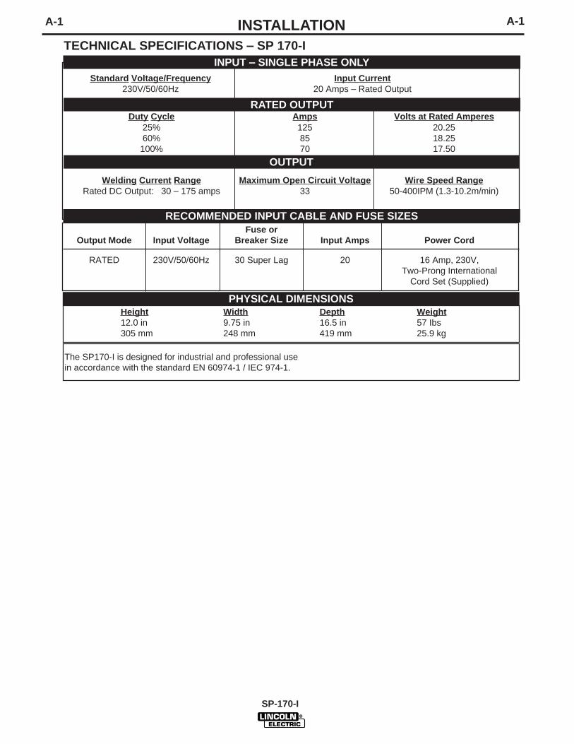
Welding Current Range Maximum Open Circuit Voltage Wire Speed RangeRated DC Output: 30 – 175 amps 33 50-400IPM (1.3-10.2m/min)
A-1A-1 INSTALLATION
Fuse orOutput Mode Input Voltage Breaker Size Input Amps Power Cord
RATED 230V/50/60Hz 30 Super Lag 20 16 Amp, 230V,Two-Prong International
Cord Set (Supplied)
TECHNICAL SPECIFICATIONS – SP 170-IINPUT – SINGLE PHASE ONLY
RATED OUTPUT
OUTPUT
RECOMMENDED INPUT CABLE AND FUSE SIZES
Height Width Depth Weight12.0 in 9.75 in 16.5 in 57 Ibs305 mm 248 mm 419 mm 25.9 kg
PHYSICAL DIMENSIONS
The SP170-I is designed for industrial and professional use in accordance with the standard EN 60974-1 / IEC 974-1.
Standard Voltage/Frequency Input Current230V/50/60Hz 20 Amps – Rated Output
A-2 A-2INSTALLATIONRead entire installation section before startinginstallation.
SAFETY PRECAUTIONS
IDENTIFY AND LOCATE COMPONENTS
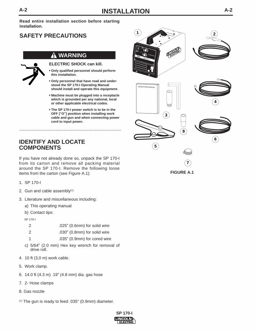
If you have not already done so, unpack the SP 170-Ifrom its carton and remove all packing materialaround the SP 170-I. Remove the following looseitems from the carton (see Figure A.1):
1. SP 170-I
2. Gun and cable assembly(1)
3. Literature and miscellaneous including:
a) This operating manual
b) Contact tips:
SP 170-I
2 .025” (0.6mm) for solid wire
2 .030” (0.8mm) for solid wire
1 .035” (0.9mm) for cored wire
c) 5/64” (2.0 mm) Hex key wrench for removal ofdrive roll.
4. 10 ft (3,0 m) work cable.
5. Work clamp.
6. 14.0 ft (4.3 m) .19” (4.8 mm) dia. gas hose
7. 2- Hose clamps
8. Gas nozzle
(1) The gun is ready to feed .035" (0.9mm) diameter.
ELECTRIC SHOCK can kill.
• Only qualified personnel should performthis installation.
• Only personnel that have read and under-stood the SP 170-I Operating Manualshould install and operate this equipment.
• Machine must be plugged into a receptaclewhich is grounded per any national, localor other applicable electrical codes.
• The SP 170-I power switch is to be in theOFF (“O”) position when installing workcable and gun and when connecting powercord to input power.
WARNING
FIGURE A.1
SP 170 -I
E
WELDINGWELDING AMPAMP RANGE
RANGE
1 2
4
6
7
8
3
5
SP 170-I
A-3A-3 INSTALLATION
SP 170-I
SELECT SUITABLE LOCATION
The SP 170-I has an IP21S rating. Locate the welderin a dry location where there is free circulation of cleanair into the louvers in the back and out the front of theunit. A location that minimizes the amount of smokeand dirt drawn into the rear louvers reduces thechance of dirt accumulation that can block air pas-sages and cause overheating.
STACKING
SP 170-I’s cannot be stacked.
TILTING
Each machine must be placed on a secure, level sur-face, either directly or on the recommended cart. Themachine may topple over if this procedure is not fol-lowed.
LIMITATIONS
The SP 170-I cannot be used for pipe thawing.
MIG welding and flux cored arc welding are the onlyprocesses supported by the SP 170-I
The handle can not be used for transport by crane.
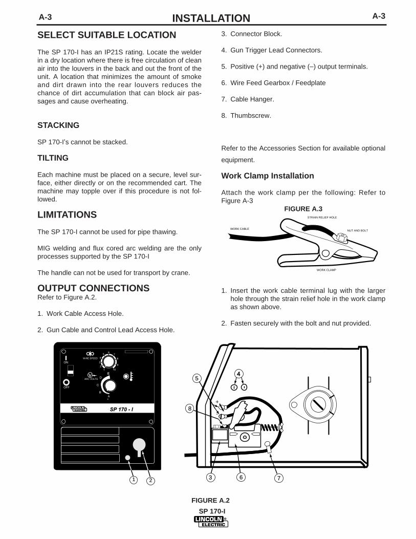
OUTPUT CONNECTIONSRefer to Figure A.2.
1. Work Cable Access Hole.
2. Gun Cable and Control Lead Access Hole.
3. Connector Block.
4. Gun Trigger Lead Connectors.
5. Positive (+) and negative (–) output terminals.
6. Wire Feed Gearbox / Feedplate
7. Cable Hanger.
8. Thumbscrew.
Refer to the Accessories Section for available optional
SP 170 - I
1 2
E 45
8
3 6 7
+
-
equipment.
Work Clamp Installation
Attach the work clamp per the following: Refer toFigure A-3
FIGURE A.3
1. Insert the work cable terminal lug with the largerhole through the strain relief hole in the work clampas shown above.
2. Fasten securely with the bolt and nut provided.
FIGURE A.2
WORK CABLE
STRAIN RELIEF HOLE
NUT AND BOLT
WORK CLAMP
A-4A-4 INSTALLATIONWork Cable Installation
Refer to Figure A.2.
1. Open the wire feed section door on the right side ofthe SP 170-I.
2. Pass the end of the work cable that has the termi-nal lug with the smaller hole through the WorkCable Access Hole (1) in the case front.
3. Route the cable under the feedplate (6) and in frontof the Wire Feed Motor.
4. For Innershield Only: Refer to Figure A.2. Asdelivered, the machine is connected for negativeelectrode polarity. This is the appropriate configu-ration for the Innershield process. To completeinstallation, use the provided wing nut to connectthe work cable’s terminal lug to the positive (+) out-put terminal (4) located above the Wire FeedGearbox (5). Make sure that both wing nuts aretight.
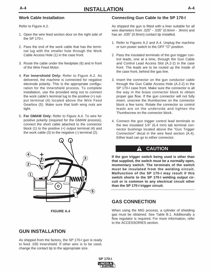
5. For GMAW Only: Refer to Figure A.4. To wire forpositive polarity (required for the GMAW process),connect the short cable attached to the connectorblock (1) to the positive (+) output terminal (4) andthe work cable (3) to the negative (-) terminal (2).
Connecting Gun Cable to the SP 170-I
As shipped the gun is fitted with a liner suitable for allwire diameters from .025” - .035” (0.6mm - .9mm) andhas an .035” (0.9mm) contact tip installed.
1. Refer to Figures A.2 and A.4. Unplug the machineor turn power switch to the OFF “O” position.
2. Pass the insulated terminals of the gun trigger con-trol leads, one at a time, through the Gun Cableand Control Lead Access Slot (A.2-2) in the casefront. The leads are to be routed up the inside ofthe case front, behind the gas line.
3. Insert the connector on the gun conductor cablethrough the Gun Cable Access Hole (A.2-2) in theSP 170-I case front. Make sure the connector is allthe way in the brass connector block to obtainproper gas flow. If the gun connector will not fullyinsert, unscrew the thumbscrew on the connectorblock a few turns. Rotate the connector so controlleads are on the underside and tighten theThumbscrew on the connector block.
4. Connect the gun trigger control lead terminals tothe two insulated 1/4" (6,4 mm) tab terminal con-nector bushings located above the “Gun TriggerConnection” decal in the wire feed section (A.4).Either lead can go to either connector.
If the gun trigger switch being used is other thanthat supplied, the switch must be a normally open,momentary switch. The terminals of the switchmust be insulated from the welding circuit.Malfunction of the SP 170-I may result if thisswitch shorts to the SP 170-I welding output cir-cuit or is common to any electrical circuit otherthan the SP 170-I trigger circuit.
GAS CONNECTION
When using the MIG process, a cylinder of shieldinggas must be obtained. See Table B.1. Additionally aflow regulator is required. For more information, referto the ACCESSORIES section.
CAUTION
FIGURE A.4
GUN INSTALLATION
As shipped from the factory, the SP 170-I gun is readyto feed .035 Innershield. If other wire is to be used,change the contact tip to the appropriate size.
1
2
34
5
SP 170-I
A-5A-5 INSTALLATION
SP 170-I
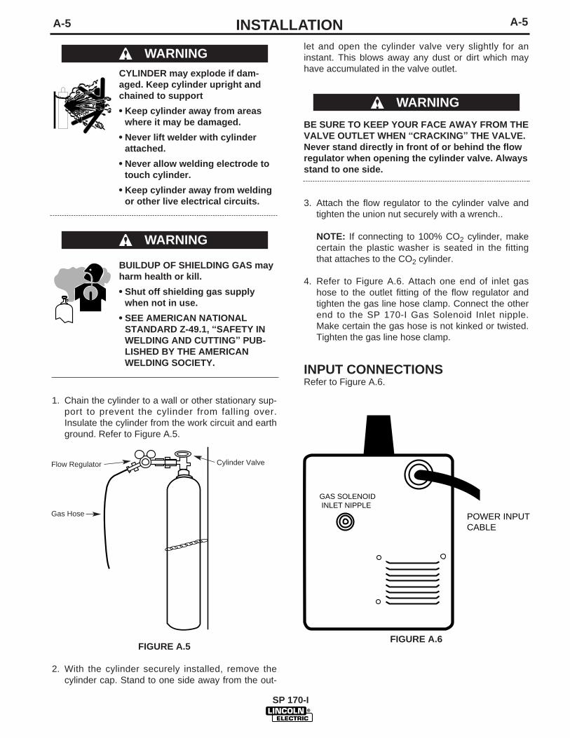
let and open the cylinder valve very slightly for aninstant. This blows away any dust or dirt which mayhave accumulated in the valve outlet.
BE SURE TO KEEP YOUR FACE AWAY FROM THEVALVE OUTLET WHEN “CRACKING” THE VALVE.Never stand directly in front of or behind the flowregulator when opening the cylinder valve. Alwaysstand to one side.
3. Attach the flow regulator to the cylinder valve andtighten the union nut securely with a wrench..
NOTE: If connecting to 100% CO2 cylinder, makecertain the plastic washer is seated in the fittingthat attaches to the CO2 cylinder.
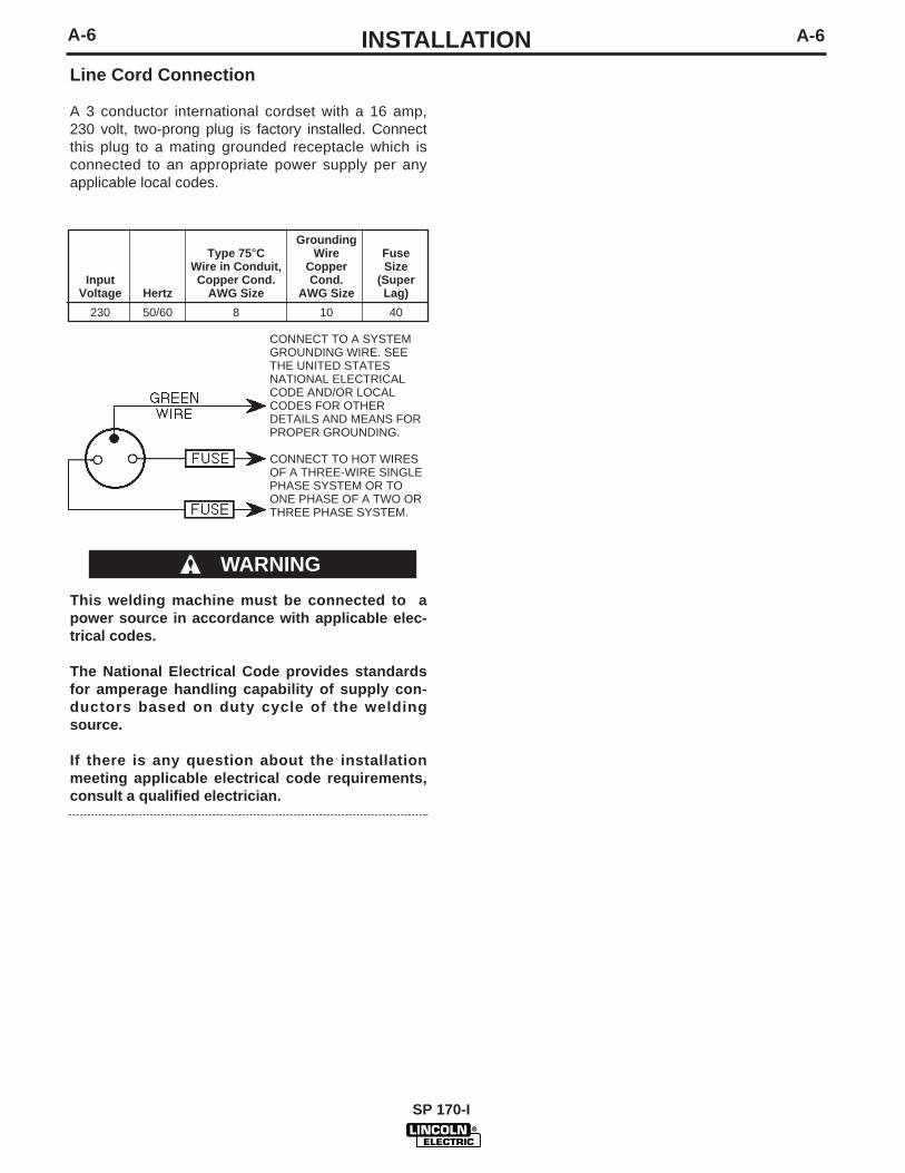
4. Refer to Figure A.6. Attach one end of inlet gashose to the outlet fitting of the flow regulator andtighten the gas line hose clamp. Connect the otherend to the SP 170-I Gas Solenoid Inlet nipple.Make certain the gas hose is not kinked or twisted.Tighten the gas line hose clamp.
INPUT CONNECTIONSRefer to Figure A.6.
FIGURE A.6
CYLINDER may explode if dam-aged. Keep cylinder upright andchained to support
• Keep cylinder away from areaswhere it may be damaged.
• Never lift welder with cylinderattached.
• Never allow welding electrode totouch cylinder.
• Keep cylinder away from weldingor other live electrical circuits.
BUILDUP OF SHIELDING GAS mayharm health or kill.
• Shut off shielding gas supplywhen not in use.
• SEE AMERICAN NATIONALSTANDARD Z-49.1, “SAFETY INWELDING AND CUTTING” PUB-LISHED BY THE AMERICANWELDING SOCIETY.
1. Chain the cylinder to a wall or other stationary sup-port to prevent the cylinder from falling over.Insulate the cylinder from the work circuit and earthground. Refer to Figure A.5.
FIGURE A.5
2. With the cylinder securely installed, remove thecylinder cap. Stand to one side away from the out-
WARNING
Cylinder Valve
Gas Hose
Flow Regulator
WARNING
WARNING
POWER INPUTCABLE
GAS SOLENOID INLET NIPPLE
A-6 A-6INSTALLATIONLine Cord Connection
A 3 conductor international cordset with a 16 amp,230 volt, two-prong plug is factory installed. Connectthis plug to a mating grounded receptacle which isconnected to an appropriate power supply per anyapplicable local codes.
CONNECT TO A SYSTEMGROUNDING WIRE. SEETHE UNITED STATESNATIONAL ELECTRICALCODE AND/OR LOCALCODES FOR OTHERDETAILS AND MEANS FORPROPER GROUNDING.
CONNECT TO HOT WIRES OF A THREE-WIRE SINGLEPHASE SYSTEM OR TOONE PHASE OF A TWO ORTHREE PHASE SYSTEM.
This welding machine must be connected to apower source in accordance with applicable elec-trical codes.
The National Electrical Code provides standardsfor amperage handling capability of supply con-ductors based on duty cycle of the weldingsource.
If there is any question about the installationmeeting applicable electrical code requirements,consult a qualified electrician.
GroundingType 75°C Wire Fuse
Wire in Conduit, Copper SizeInput Copper Cond. Cond. (Super
Voltage Hertz AWG Size AWG Size Lag)
230 50/60 8 10 40
WARNING
SP 170-I
SP-170-I
B-1 B-1OPERATION
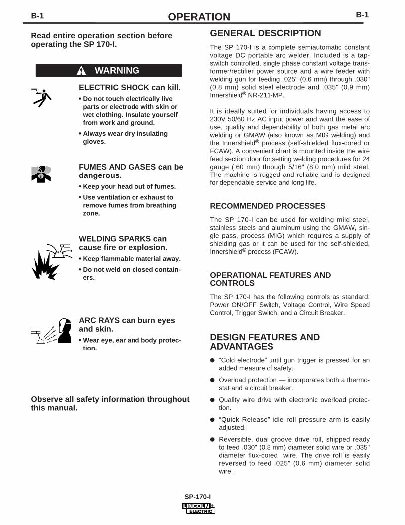
Read entire operation section beforeoperating the SP 170-I.
ELECTRIC SHOCK can kill.• Do not touch electrically live
parts or electrode with skin orwet clothing. Insulate yourselffrom work and ground.
• Always wear dry insulatinggloves.
FUMES AND GASES can bedangerous.• Keep your head out of fumes.
• Use ventilation or exhaust toremove fumes from breathingzone.
WELDING SPARKS cancause fire or explosion.• Keep flammable material away.
• Do not weld on closed contain-ers.
ARC RAYS can burn eyesand skin.• Wear eye, ear and body protec-
tion.
Observe all safety information throughoutthis manual.
WARNING
GENERAL DESCRIPTIONThe SP 170-I is a complete semiautomatic constantvoltage DC portable arc welder. Included is a tap-switch controlled, single phase constant voltage trans-former/rectifier power source and a wire feeder withwelding gun for feeding .025" (0.6 mm) through .030"(0.8 mm) solid steel electrode and .035" (0.9 mm)Innershield® NR-211-MP.
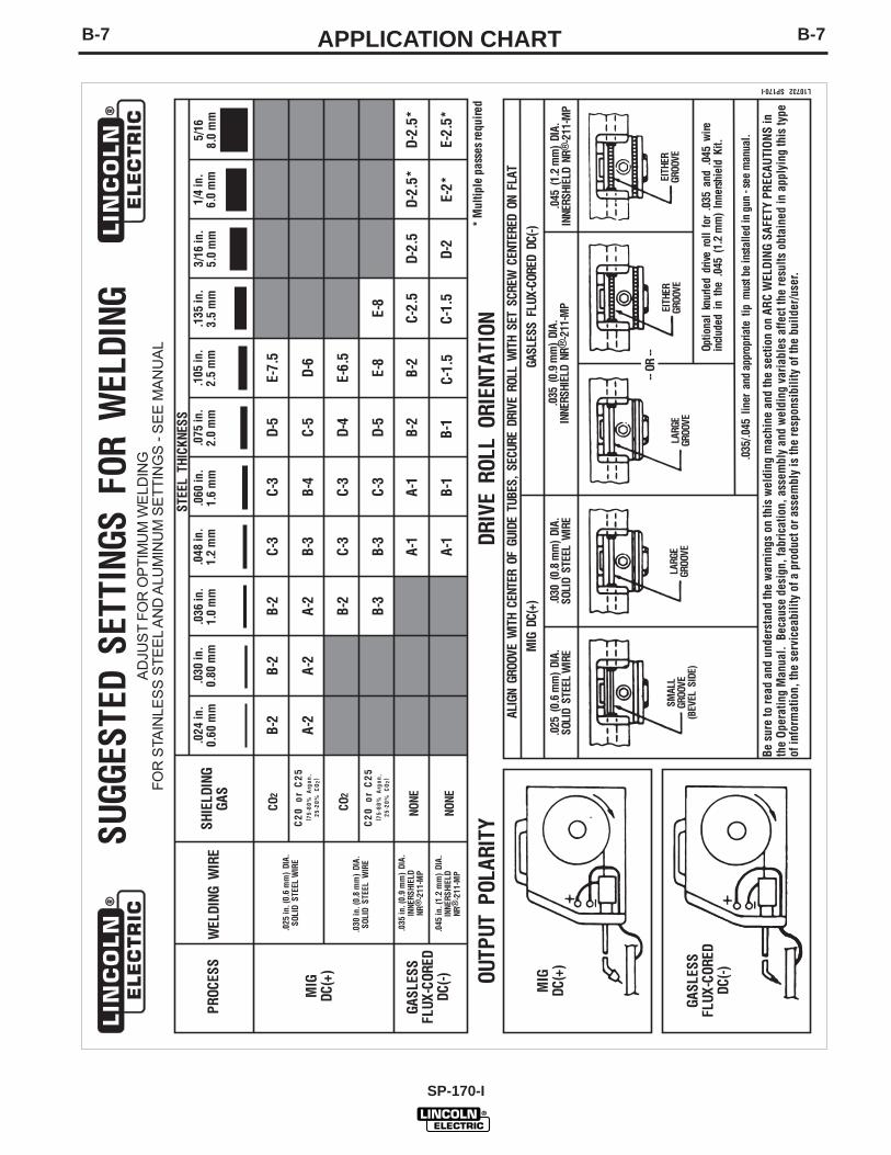
It is ideally suited for individuals having access to230V 50/60 Hz AC input power and want the ease ofuse, quality and dependability of both gas metal arcwelding or GMAW (also known as MIG welding) andthe Innershield® process (self-shielded flux-cored orFCAW). A convenient chart is mounted inside the wirefeed section door for setting welding procedures for 24gauge (.60 mm) through 5/16" (8.0 mm) mild steel.The machine is rugged and reliable and is designedfor dependable service and long life.
RECOMMENDED PROCESSES
The SP 170-I can be used for welding mild steel,stainless steels and aluminum using the GMAW, sin-gle pass, process (MIG) which requires a supply ofshielding gas or it can be used for the self-shielded,Innershield® process (FCAW).
OPERATIONAL FEATURES AND CONTROLS
The SP 170-I has the following controls as standard:Power ON/OFF Switch, Voltage Control, Wire SpeedControl, Trigger Switch, and a Circuit Breaker.
DESIGN FEATURES AND ADVANTAGES● “Cold electrode” until gun trigger is pressed for an
added measure of safety.
● Overload protection — incorporates both a thermo-stat and a circuit breaker.
● Quality wire drive with electronic overload protec-tion.
● “Quick Release” idle roll pressure arm is easilyadjusted.
● Reversible, dual groove drive roll, shipped readyto feed .030" (0.8 mm) diameter solid wire or .035"diameter flux-cored wire. The drive roll is easilyreversed to feed .025" (0.6 mm) diameter solidwire.
●
B-2B-2 OPERATION● No external shielding gas is required when used
with Lincoln Innershield .035” (0,9 mm) NR®-211-MP electrode.
● Spindle accommodates both 8 in. (200 mm) diame-ter and 4 in. (100 mm) diameter spools of wire.
WELDING CAPABILITYThe SP 170-I is rated at 125 amps, 20.25 volts, at25% duty cycle on a ten minute basis. It is capable ofhigher output currents at lower duty cycles. Actualwelding outputs will range between 30 and 175 ampsfor the recommended processes.
LIMITATIONSArc Gouging cannot be performed with the SP 170-I.The SP 170-I is not recommended for pipe thawing orTIG welding.
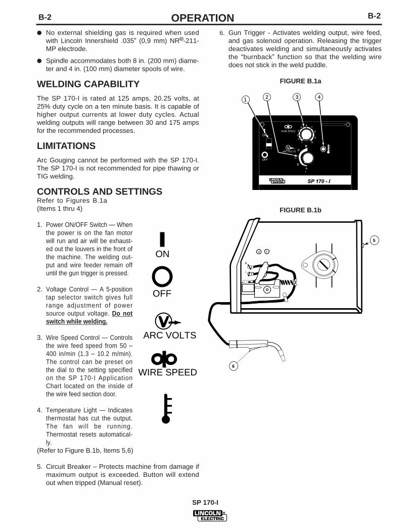
CONTROLS AND SETTINGSRefer to Figures B.1a(Items 1 thru 4)
1. Power ON/OFF Switch — Whenthe power is on the fan motorwill run and air will be exhaust-ed out the louvers in the front ofthe machine. The welding out-put and wire feeder remain offuntil the gun trigger is pressed.
2. Voltage Control — A 5-positiontap selector switch gives fullrange adjustment of powersource output voltage. Do notswitch while welding.
3. Wire Speed Control — Controlsthe wire feed speed from 50 –400 in/min (1.3 – 10.2 m/min).The control can be preset onthe dial to the setting specifiedon the SP 170-I ApplicationChart located on the inside ofthe wire feed section door.
4. Temperature Light — Indicatesthermostat has cut the output.The fan wil l be running.Thermostat resets automatical-ly.
(Refer to Figure B.1b, Items 5,6)
5. Circuit Breaker – Protects machine from damage ifmaximum output is exceeded. Button will extendout when tripped (Manual reset).
OFF
ON
ARC VOLTS
WIRE SPEED
6. Gun Trigger - Activates welding output, wire feed,and gas solenoid operation. Releasing the triggerdeactivates welding and simultaneously activatesthe “burnback” function so that the welding wiredoes not stick in the weld puddle.
FIGURE B.1a
FIGURE B.1b
SP 170 - I
1 2 3 4
E
5
6
SP 170-I
B-3 B-3OPERATIONWELDING OPERATIONS
SEQUENCE OF OPERATION
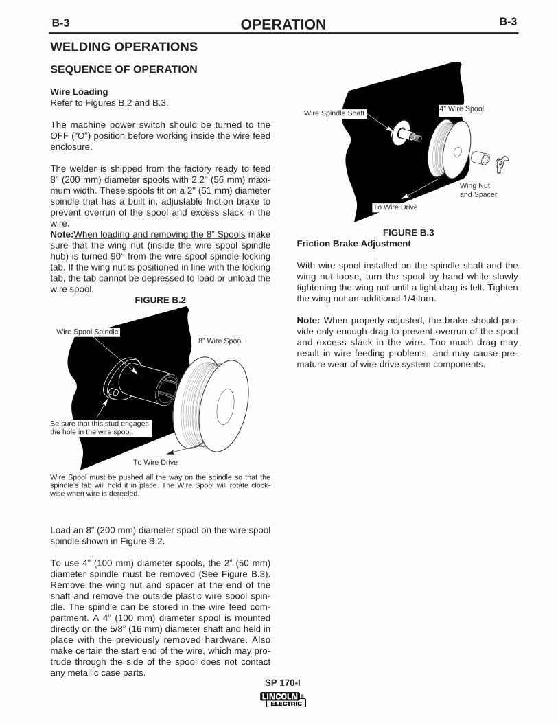
Wire LoadingRefer to Figures B.2 and B.3.
The machine power switch should be turned to theOFF (“O”) position before working inside the wire feedenclosure.
The welder is shipped from the factory ready to feed8" (200 mm) diameter spools with 2.2" (56 mm) maxi-mum width. These spools fit on a 2" (51 mm) diameterspindle that has a built in, adjustable friction brake toprevent overrun of the spool and excess slack in the wire.Note:When loading and removing the 8” Spools makesure that the wing nut (inside the wire spool spindlehub) is turned 90° from the wire spool spindle lockingtab. If the wing nut is positioned in line with the lockingtab, the tab cannot be depressed to load or unload thewire spool.
FIGURE B.2
Load an 8” (200 mm) diameter spool on the wire spoolspindle shown in Figure B.2.
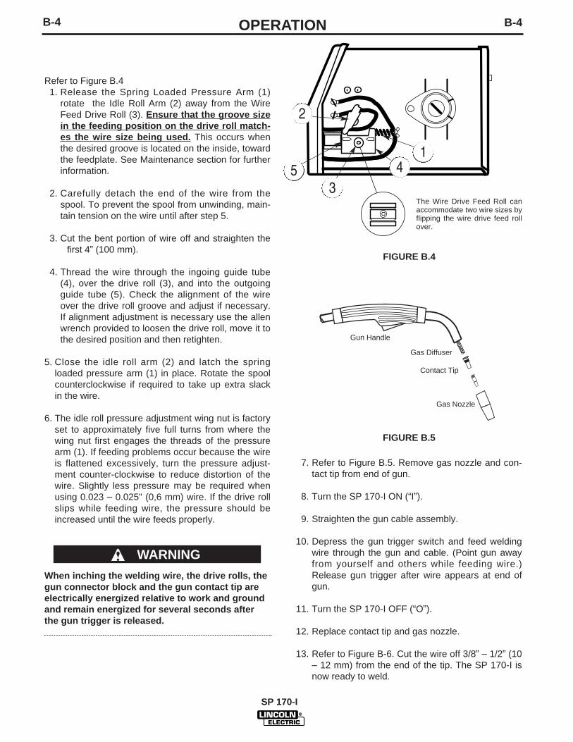
To use 4” (100 mm) diameter spools, the 2” (50 mm)diameter spindle must be removed (See Figure B.3).Remove the wing nut and spacer at the end of theshaft and remove the outside plastic wire spool spin-dle. The spindle can be stored in the wire feed com-partment. A 4” (100 mm) diameter spool is mounteddirectly on the 5/8” (16 mm) diameter shaft and held inplace with the previously removed hardware. Alsomake certain the start end of the wire, which may pro-trude through the side of the spool does not contactany metallic case parts.
FIGURE B.3Friction Brake Adjustment
With wire spool installed on the spindle shaft and thewing nut loose, turn the spool by hand while slowlytightening the wing nut until a light drag is felt. Tightenthe wing nut an additional 1/4 turn.
Note: When properly adjusted, the brake should pro-vide only enough drag to prevent overrun of the spooland excess slack in the wire. Too much drag mayresult in wire feeding problems, and may cause pre-mature wear of wire drive system components.
Wire Spool must be pushed all the way on the spindle so that thespindle’s tab will hold it in place. The Wire Spool will rotate clock-wise when wire is dereeled.
8” Wire Spool
To Wire Drive
Wire Spool Spindle
Be sure that this stud engagesthe hole in the wire spool.
Wire Spindle Shaft
To Wire Drive
4" Wire Spool
Wing Nut and Spacer
SP 170-I
B-4B-4 OPERATION
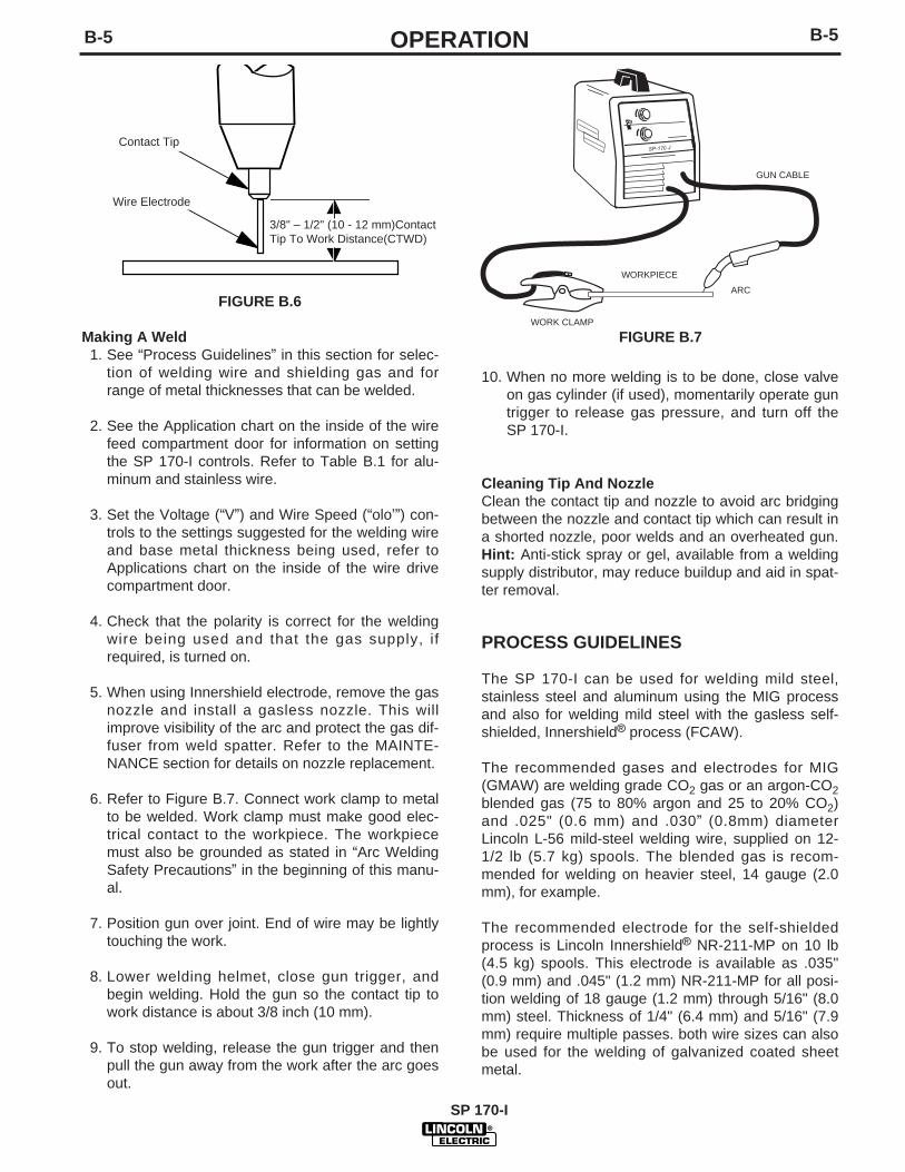
Refer to Figure B.41. Release the Spring Loaded Pressure Arm (1)
rotate the Idle Roll Arm (2) away from the WireFeed Drive Roll (3). Ensure that the groove sizein the feeding position on the drive roll match-es the wire size being used. This occurs whenthe desired groove is located on the inside, towardthe feedplate. See Maintenance section for furtherinformation.
2. Carefully detach the end of the wire from thespool. To prevent the spool from unwinding, main-tain tension on the wire until after step 5.
3. Cut the bent portion of wire off and straighten thefirst 4” (100 mm).
4. Thread the wire through the ingoing guide tube(4), over the drive roll (3), and into the outgoingguide tube (5). Check the alignment of the wireover the drive roll groove and adjust if necessary.If alignment adjustment is necessary use the allenwrench provided to loosen the drive roll, move it tothe desired position and then retighten.
5. Close the idle roll arm (2) and latch the springloaded pressure arm (1) in place. Rotate the spoolcounterclockwise if required to take up extra slackin the wire.
6. The idle roll pressure adjustment wing nut is factoryset to approximately five full turns from where thewing nut first engages the threads of the pressurearm (1). If feeding problems occur because the wireis flattened excessively, turn the pressure adjust-ment counter-clockwise to reduce distortion of thewire. Slightly less pressure may be required whenusing 0.023 – 0.025" (0,6 mm) wire. If the drive rollslips while feeding wire, the pressure should beincreased until the wire feeds properly.
When inching the welding wire, the drive rolls, thegun connector block and the gun contact tip areelectrically energized relative to work and groundand remain energized for several seconds afterthe gun trigger is released.
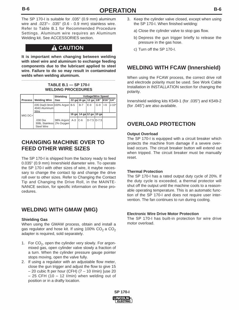
7. Refer to Figure B.5. Remove gas nozzle and con-tact tip from end of gun.
8. Turn the SP 170-I ON (“I”).
9. Straighten the gun cable assembly.
10. Depress the gun trigger switch and feed weldingwire through the gun and cable. (Point gun awayfrom yourself and others while feeding wire.)Release gun trigger after wire appears at end ofgun.
11. Turn the SP 170-I OFF (“O”).
12. Replace contact tip and gas nozzle.
13. Refer to Figure B-6. Cut the wire off 3/8” – 1/2” (10– 12 mm) from the end of the tip. The SP 170-I isnow ready to weld.
WARNING
FIGURE B.4
The Wire Drive Feed Roll canaccommodate two wire sizes byflipping the wire drive feed rollover.
FIGURE B.5
1
2
345
SP 170-I
Gun Handle
Contact Tip
Gas Diffuser
Gas Nozzle
B-5 B-5OPERATION
Making A Weld1. See “Process Guidelines” in this section for selec-
tion of welding wire and shielding gas and forrange of metal thicknesses that can be welded.
2. See the Application chart on the inside of the wirefeed compartment door for information on settingthe SP 170-I controls. Refer to Table B.1 for alu-minum and stainless wire.
3. Set the Voltage (“V”) and Wire Speed (“olo’”) con-trols to the settings suggested for the welding wireand base metal thickness being used, refer to
3. Applications chart on the inside of the wire drivecompartment door.
4. Check that the polarity is correct for the weldingwire being used and that the gas supply, ifrequired, is turned on.
5. When using Innershield electrode, remove the gasnozzle and install a gasless nozzle. This willimprove visibility of the arc and protect the gas dif-fuser from weld spatter. Refer to the MAINTE-NANCE section for details on nozzle replacement.
6. Refer to Figure B.7. Connect work clamp to metalto be welded. Work clamp must make good elec-trical contact to the workpiece. The workpiecemust also be grounded as stated in “Arc WeldingSafety Precautions” in the beginning of this manu-al.
7. Position gun over joint. End of wire may be lightlytouching the work.
8. Lower welding helmet, close gun trigger, andbegin welding. Hold the gun so the contact tip towork distance is about 3/8 inch (10 mm).
9. To stop welding, release the gun trigger and thenpull the gun away from the work after the arc goesout.
FIGURE B.6
10. When no more welding is to be done, close valveon gas cylinder (if used), momentarily operate guntrigger to release gas pressure, and turn off theSP 170-I.
Cleaning Tip And NozzleClean the contact tip and nozzle to avoid arc bridgingbetween the nozzle and contact tip which can result ina shorted nozzle, poor welds and an overheated gun.Hint: Anti-stick spray or gel, available from a weldingsupply distributor, may reduce buildup and aid in spat-ter removal.
PROCESS GUIDELINES
The SP 170-I can be used for welding mild steel,stainless steel and aluminum using the MIG processand also for welding mild steel with the gasless self-shielded, Innershield® process (FCAW).
The recommended gases and electrodes for MIG(GMAW) are welding grade CO2 gas or an argon-CO2blended gas (75 to 80% argon and 25 to 20% CO2)and .025" (0.6 mm) and .030” (0.8mm) diameterLincoln L-56 mild-steel welding wire, supplied on 12-1/2 lb (5.7 kg) spools. The blended gas is recom-mended for welding on heavier steel, 14 gauge (2.0mm), for example.
The recommended electrode for the self-shieldedprocess is Lincoln Innershield® NR-211-MP on 10 lb(4.5 kg) spools. This electrode is available as .035"(0.9 mm) and .045" (1.2 mm) NR-211-MP for all posi-tion welding of 18 gauge (1.2 mm) through 5/16" (8.0mm) steel. Thickness of 1/4" (6.4 mm) and 5/16" (7.9mm) require multiple passes. both wire sizes can alsobe used for the welding of galvanized coated sheetmetal.
3/8" – 1/2" (10 - 12 mm)ContactTip To Work Distance(CTWD)
Contact Tip
Wire Electrode
FIGURE B.7
SP-170 -I
WORKPIECE
GUN CABLE
ARC
WORK CLAMP
SP 170-I
B-6
SP 170-I
B-6 OPERATIONThe SP 170-I is suitable for .035" (0.9 mm) aluminumwire and .023"– .035" (0.6 - 0.9 mm) stainless wire.Refer to Table B.1 for Recommended ProcedureSettings. Aluminum wire requires an AluminumWelding kit. See ACCESSORIES section.
It is important when changing between weldingwith steel wire and aluminum to exchange feedingcomponents due to the lubricant applied to steelwire. Failure to do so may result in contaminatedwelds when welding aluminum.------------------------------------------------------------------------
TABLE B.1 — SP 170-I WELDING PROCEDURES
CHANGING MACHINE OVER TOFEED OTHER WIRE SIZES
The SP 170-I is shipped from the factory ready to feed0.035" (0.9 mm) Innershield diameter wire. To operatethe SP 170-I with other sizes of wire, it maybe neces-sary to change the contact tip and change the driveroll over to other sizes. Refer to Changing the ContactTip and Changing the Drive Roll, in the MAINTE-NANCE section, for specific information on these pro-cedures.
WELDING WITH GMAW (MIG)
Shielding GasWhen using the GMAW process, obtain and install agas regulator and hose kit. If using 100% CO2 a CO2adapter is required, sold separately.
1. For CO2, open the cylinder very slowly. For argon-mixed gas, open cylinder valve slowly a fraction ofa turn. When the cylinder pressure gauge pointerstops moving, open the valve fully.
2. If using a regulator with an adjustable flow meter,close the gun trigger and adjust the flow to give 15– 20 cubic ft per hour (CFH) (7 – 10 I/min) [use 20– 25 CFH (10 – 12 I/min) when welding out ofposition or in a drafty location.
3. Keep the cylinder valve closed, except when usingthe SP 170-I. When finished welding:
a) Close the cylinder valve to stop gas flow.
b) Depress the gun trigger briefly to release thepressure in the gas hose.
c) Turn off the SP 170-I.
WELDING WITH FCAW (Innershield)
When using the FCAW process, the correct drive rolland electrode polarity must be used. See Work CableInstallation in INSTALLATION section for changing thepolarity.
Innershield welding kits K549-1 (for .035") and K549-2(for .045") are also available.
OVERLOAD PROTECTION
Output OverloadThe SP 170-I is equipped with a circuit breaker whichprotects the machine from damage if a severe over-load occurs. The circuit breaker button will extend outwhen tripped. The circuit breaker must be manuallyreset.
Thermal ProtectionThe SP 170-I has a rated output duty cycle of 20%. Ifthe duty cycle is exceeded, a thermal protector willshut off the output until the machine cools to a reason-able operating temperature. This is an automatic func-tion of the SP 170-I and does not require user inter-vention. The fan continues to run during cooling.
Electronic Wire Drive Motor ProtectionThe SP 170-I has built-in protection for wire drivemotor overload.
CAUTION
Shielding Voltage/Wire SpeedProcess Welding Wire Gas 22 ga 16 ga 12 ga 1/8” 3/16” 1/4”
See Maintenance section for instructions oninstalling drive roll, cable liner, contact tip and theirproper configuration.
1. KP665-045C Drive Roll – Optional — Knurleddrive roll for feeding .035 - .045” (0.9 - 1.2 mm)diameter flux-cored electrode.
2. K520 Utility Cart — Designed to transport theLincoln family of small welders. Has provisions formounting a single gas cylinder. Has front castersand large rear wheels. Handle height is easilyadjustable. Bottom tray provided for tools andaccessories. Easy assembly required; takes lessthan 15 minutes.
3. K464 .035" (0.9 mm) Innershield® Welding Kit— Includes a contact tip, a gasless nozzle and a.035/.045" (0.9/1.2 mm) cable liner to permit thegun and cable to use .035" (0.9 mm) diameter flux-cored electrode. The fitting on the end of the lineris stenciled with the maximum rated wire size(.045"/1.2 mm). Also included is a 10 lb.(4.5 kg.)spool of .035" (0.9 mm) Innershield® NR-211-MP.
For use with “Lincoln Electric®” gun (with blacktrigger). The end of the brass fitting on the end ofthe .035/.045” (0.9/1.2mm) liner is color codedgreen. (The .023-.030” (0.6-0.8mm) liner is colorcoded orange).
See “Innershield (FCAW) Conversion” in this sec-tion for installation instructions and MAINTE-NANCE section for proper feeding component con-figuration and installation.
4. K491 .045" (1.2 mm) Innershield® Welding Kit— Includes a contact tip, a gasless nozzle and a.035/.045" (0.9/1.2 mm) cable liner to permit thegun and cable to use .045" (1.2 mm) diameter flux-cored electrode. The fitting on the end of the lineris stenciled with the maximum rated wire size(.045"/1.2 mm). Also included is a 10 lb.(4.5 kg.)spool of .045" (1.2 mm) Innershield® NR-211-MPand a knurled drive roll for .035” (0.9mm) and .045”(1.2mm) wire.
For use with “Lincoln Electric®” gun (with blacktrigger). The end of the brass fitting on the end ofthe .035/.045” (0.9/1.2mm) liner is color codedgreen. (The .023-.030” (0.6-0.8mm) liner is colorcoded orange).
See “Innershield (FCAW) Conversion” in this sec-tion for installation instructions and MAINTE-NANCE section for proper feeding component con-figuration and installation.
SP-170-I
C-2 C-2ACCESSORIESMIG (GMAW)CONVERSION
Several changes are needed to convert the unit foroperation with the MIG (GMAW) process. The follow-ing conversions should be reviewed before weldingwith (GMAW):
1. Change the output polarity to DC(+). See “WorkCable Installation” in Installation section for details.
2. Install proper drive roll for the wire size selected.See “Changing Drive Roll” in Maintenance sectionfor details.
3. Install the proper gun liner and tip for the wire sizeselected. See “Component Replacement” inMaintenance section for details.
4. Remove gasless nozzle (if installed) and install gasnozzle.
5. Load wire into machine and thread into gun andcable per “Welding Wire Loading” section.
REPLACEMENT PARTS
Complete Gun and Cable Assembly (Code 10983)L11951
Complete Gun and Cable Assembly (Code 10982)L8311-5
SP 170-I
MAINTENANCE
SAFETY PRECAUTIONS
ELECTRIC SHOCK can kill.
• Disconnect input power by removing plugfrom receptacle before working insideSP170-I. Use only grounded receptacle. Donot touch electrically “hot” parts insideSP 170-I.
• Have qualified personnel do the mainte-nance and trouble shooting work.
ROUTINE MAINTENANCE
POWER SOURCE COMPARTMENTIn extremely dusty locations, dirt may clog the air passagescausing the welder to run hot. Blow dirt out of the welder withlow pressure air at regular intervals to eliminate excessive dirtand dust build-up on interval parts.
WIRE FEED COMPARTMENT
1. When necessary, vacuum accumulated dirt from gearbox andwire feed section.
2. Occasionally inspect the incoming guide tube and cleaninside diameter if necessary.
3. Motor and gearbox have lifetime lubrication and require nomaintenance.
FAN MOTOR
Has lifetime lubrication — requires no maintenance.
WIRE REEL SPINDLE
Requires no maintenance. Do not lubricate shaft.
D-1D-1 MAINTENANCE
SP 170-I
WARNING
D-2
SP-170-I
D-2 MAINTENANCEGUN AND CABLE MAINTENANCE
Gun Cable CleaningClean cable liner after using approximately 300 lbs(136 kg) of solid wire or 50 lbs (23 kg) of flux-coredwire. Remove the cable from the wire feeder and lay itout straight on the floor. Remove the contact tip fromthe gun. Using low pressure air, gently blow out thecable liner from the gas diffuser end.
Excessive pressure at the start may cause the dirtto form a plug.
Flex the cable over its entire length and again blowout the cable. Repeat this procedure until no furtherdirt comes out.
Contact Tips, Nozzles, and Gun Tubes1. Dirt can accumulate in the contact tip hole and
restrict wire feeding. After each spool of wire isused, remove the contact tip and clean it by push-ing a short piece of wire through the tip repeatedly.Use the wire as a reamer to remove dirt that maybe adhering to the wall of the hole through the tip.
2. Replace worn contact tips as required. A variableor “hunting” arc is a typical symptom of a worn con-tact tip. To install a new tip, choose the correct sizecontact tip for the electrode being used (wire size isstenciled on the side of the contact tip) and screw itsnugly into the gas diffuser.
3. Remove spatter from inside of gas nozzle and fromtip after each 10 minutes of arc time or as required.
4. Be sure the gas nozzle is fully screwed onto thediffuser for gas shielded processes. For theInnershield® process, the gasless nozzle should bescrewed onto the diffuser.
5. To remove gun tube from gun, remove gas nozzleor gasless nozzle and remove diffuser from guntube. Remove the four screws from the gun handleand separate the handle halves. (For L8311-5 gunand cable handle half says magnum 100L.Remove both collars from each end of the gunhandle and separate the handle halves). Loosenthe locking nut holding the gun tube in placeagainst the gun end cable connector. Unscrew guntube from cable connector. To install gun tube,screw the locking nut on the gun tube as far aspossible. Then screw the gun tube into the cableconnector until it bottoms. Then unscrew (no morethan one turn) the gun tube until its axis is perpen-dicular to the flat sides of the cable connector andpointed in the direction of the trigger. Tighten thelocking nut so as to maintain the proper relation-ship between the gun tube and the cable connec-tor. Replace the gun handle, trigger and diffuser.Replace the gas nozzle or gasless nozzle.
CAUTION
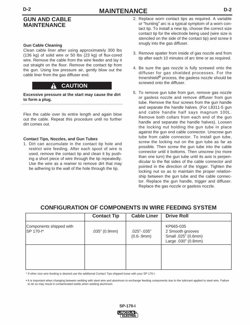
CONFIGURATION OF COMPONENTS IN WIRE FEEDING SYSTEMContact Tip Cable Liner Drive Roll
* If other size wire feeding is desired use the additional Contact Tips shipped loose with your SP 170-I.
• It is important when changing between welding with steel wire and aluminum to exchange feeding components due to the lubricant applied to steel wire. Failureto do so may result in contaminated welds when welding aluminum.
D-3D-3 MAINTENANCE
SP 170-I
COMPONENTREPLACEMENTPROCEDURES
CHANGING THE CONTACT TIP (Theseinstructions pertain to the Lincoln Electric® gun. Theinstructions for the Magnum™ 100L gun, are similarexcept that the gas nozzle is threaded.)
1. Refer to Figure D.2a or D.2b. Remove the gas noz-zle from the gun by pulling and rotating it clockwiseoff the diffuser. (Threadless slip fit).
2. Remove the existing contact tip from the gun bygripping it with pliers and twisting counter-clock-wise. Tip will now slip out of diffuser.
3. Insert new tip into diffuser. Grip it with pliers, pushtip into diffuser until it bottoms, then twist clockwiseto tighten.
4. Replace gas nozzle.
CHANGING DRIVE ROLL
The drive roll has two grooves; one for .023" – .025"(0.6 mm) solid steel electrode and a larger groove for.030" (0.8 mm) solid and .035" (0.9 mm) flux-coredsteel electrode. As shipped, the drive roll is installed inthe .030"-.035" (0.8/0.9mm) position.
If .023"/.025" (0.6mm) wire is to be used, the drive rollmust be reversed as follows:
1. Connect the machine to its rated input power perinstructions in Installation section.
2. Release the spring-loaded pressure arm and lift theidle roll arm away from the drive roll.
3. Turn the power switch to ON (marked “I”).
4. Set the wire speed to minimum and jog the driveunit with the trigger switch until the drive roll setscrew is facing up.
When inching the welding wire, the drive rolls,gun connector block, and gun contact tip areenergized relative to work and ground and remainenergized for several seconds after the gun trig-ger is released.
5. Turn the power switch to OFF (marked “O”).6. Loosen the drive roll set screw with the 5/64" (2.0
mm) hex wrench supplied.
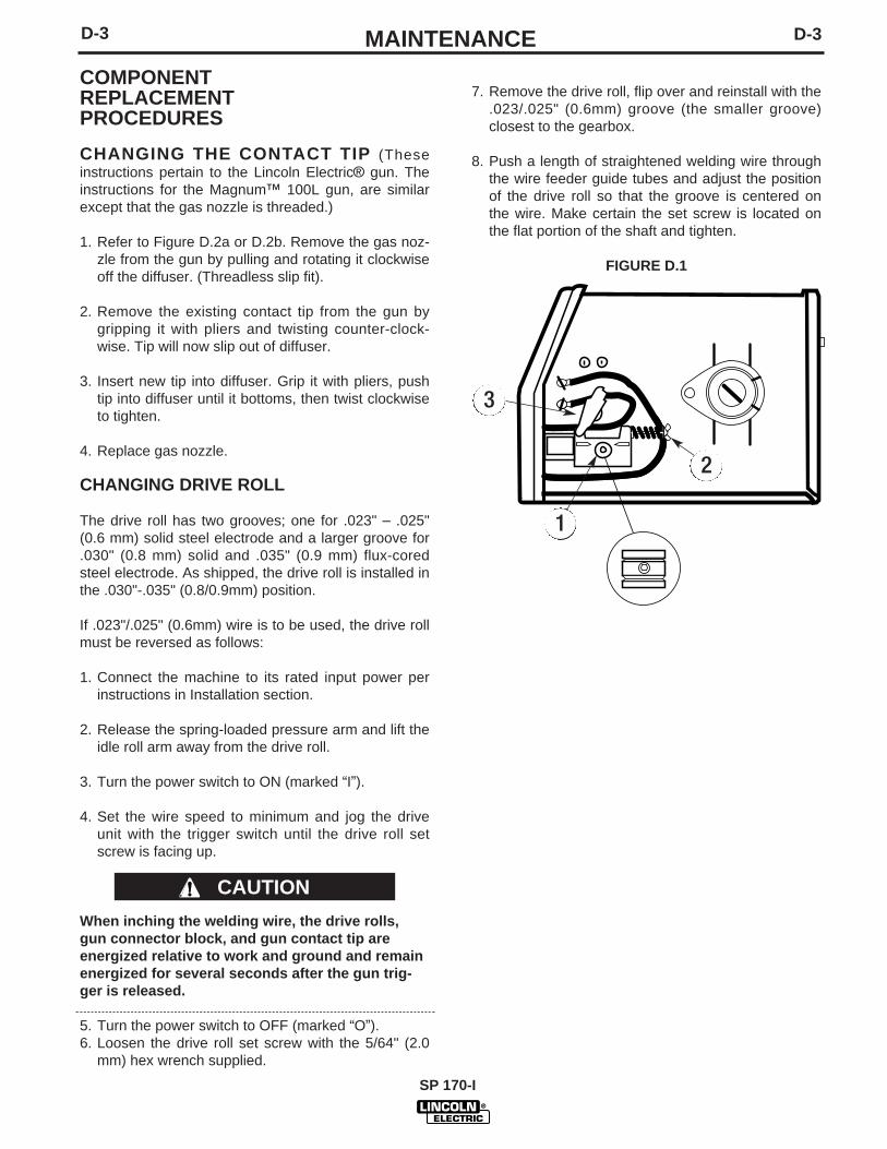
7. Remove the drive roll, flip over and reinstall with the.023/.025" (0.6mm) groove (the smaller groove)closest to the gearbox.
8. Push a length of straightened welding wire throughthe wire feeder guide tubes and adjust the positionof the drive roll so that the groove is centered onthe wire. Make certain the set screw is located onthe flat portion of the shaft and tighten.
FIGURE D.1
CAUTION
3
2
1
D-4 D-4MAINTENANCE
SP 170-I
CHANGING LINER
NOTICE: The variation in cable lengths pre-vents the interchangeability of liners. Once aliner has been cut for a particular gun, itshould not be installed in another gun unlessit can meet the liner cutoff length require-ment. Refer to Figure D.2a or D.2b.
1. Remove the gas nozzle from the gun(threadless slip-fit or threaded).
2. Remove the existing contact tip from thegun by twisting counter-clockwise.
3. If the gun is a Magnum 100L Fig D.2b.Remove the gas diffuser from the gun tube by unscrewing counter-clockwise.
4. Lay the gun and cable out straight on aflat surface. Loosen the set screw locatedin the brass connector at the wire feederend of the cable. Pull the liner out of thecable.
5. Insert a new untrimmed liner into the con-nector end of the cable. Be sure the linerbushing is stenciled appropriately for thewire size being used.
6. Fully seat the liner bushing into the con-nector. Tighten the set screw on the brasscable connector.
7A. (For Gun Shown in Fig D.2a)With the torch extended straight out, cutthe liner flush with the end of the diffuser.Rotate the gun clockwise until the linerprotrudes out the end of the diffuserenough to cut off an additional 2 coils(approx. 2mm). Rotate the handle back tothe original position.
7B. (For Gun Shown in Fig D.2b)With the gas nozzle and diffuser removedfrom the gun tube, be sure the cable isstraight, and then trim the liner to thelength shown in the Figure D.2b. Removeany burrs from the end of the liner. Screwthe gas diffuser onto the end of the guntube and securely tighten.
8. Replace the contact tip and nozzle.
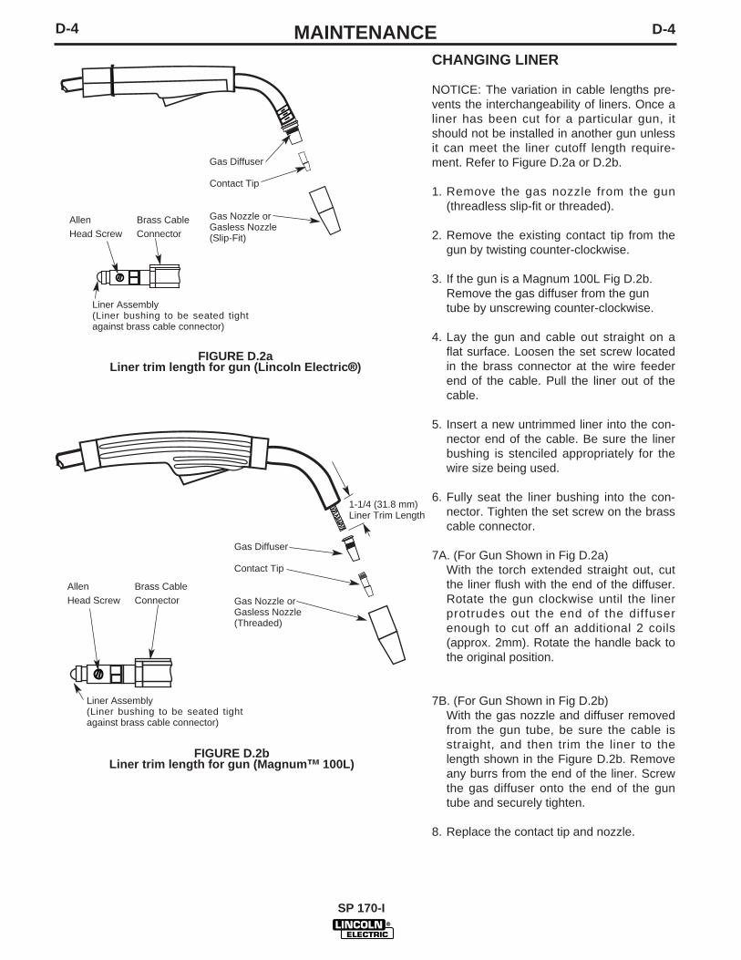
Gas Diffuser
Contact Tip
Gas Nozzle orGasless Nozzle(Slip-Fit)
Allen Brass CableHead Screw Connector
Liner Assembly (Liner bushing to be seated tightagainst brass cable connector)
FIGURE D.2aLiner trim length for gun (Lincoln Electric®)
1-1/4 (31.8 mm)Liner Trim Length
Gas Diffuser
Contact Tip
Gas Nozzle orGasless Nozzle(Threaded)
Liner Assembly (Liner bushing to be seated tightagainst brass cable connector)
FIGURE D.2bLiner trim length for gun (Magnum™ 100L)
Allen Brass CableHead Screw Connector
D-5D-5 MAINTENANCE
SP 170-I
GUN HANDLE PARTS (Lincoln Electric)
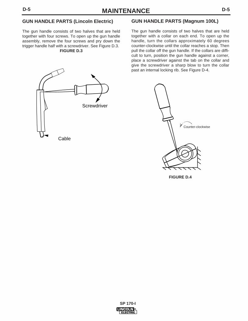
The gun handle consists of two halves that are heldtogether with four screws. To open up the gun handleassembly, remove the four screws and pry down thetrigger handle half with a screwdriver. See Figure D.3.
FIGURE D.3
Screwdriver
Cable
GUN HANDLE PARTS (Magnum 100L)
The gun handle consists of two halves that are heldtogether with a collar on each end. To open up thehandle, turn the collars approximately 60 degreescounter-clockwise until the collar reaches a stop. Thenpull the collar off the gun handle. If the collars are diffi-cult to turn, position the gun handle against a corner,place a screwdriver against the tab on the collar andgive the screwdriver a sharp blow to turn the collarpast an internal locking rib. See Figure D-4.
FIGURE D.4
➣
Counter-clockwise
E-1E-1 TROUBLESHOOTING
SP 170-I
This Troubleshooting Guide is provided to help youlocate and repair possible machine malfunctions.Simply follow the three-step procedure listed below.
Step 1. LOCATE PROBLEM (SYMPTOM).Look under the column labeled “PROBLEM (SYMP-TOMS)”. This column describes possible symptomsthat the machine may exhibit. Find the listing thatbest describes the symptom that the machine isexhibiting.
Step 2. POSSIBLE CAUSE.The second column labeled “POSSIBLE CAUSE” liststhe obvious external possibilities that may contributeto the machine symptom.
Step 3. RECOMMENDED COURSE OF ACTIONThis column provides a course of action for thePossible Cause, generally it states to contact yourlocal Lincoln Authorized Field Service Facility.
If you do not understand or are unable to perform theRecommended Course of Action safely, contact yourlocal Lincoln Authorized Field Service Facility.
HOW TO USE TROUBLESHOOTING GUIDE
Service and Repair should only be performed by Lincoln Electric Factory Trained Personnel.Unauthorized repairs performed on this equipment may result in danger to the technician andmachine operator and will invalidate your factory warranty. For your safety and to avoid ElectricalShock, please observe all safety notes and precautions detailed throughout this manual.
If for any reason you do not understand the test procedures or are unable to perform the tests/repairs safely, contact yourLocal Lincoln Authorized Field Service Facility for technical troubleshooting assistance before you proceed.
CAUTION
E-2 E-2TROUBLESHOOTING
SP 170-I
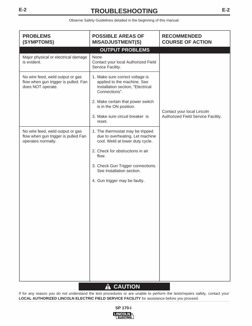
Observe Safety Guidelines detailed in the beginning of this manual.
PROBLEMS(SYMPTOMS)
Major physical or electrical damageis evident.
No wire feed, weld output or gasflow when gun trigger is pulled. Fandoes NOT operate.
No wire feed, weld output or gasflow when gun trigger is pulled Fanoperates normally.
POSSIBLE AREAS OFMISADJUSTMENT(S)
NoneContact your local Authorized FieldService Facility.
1. Make sure correct voltage isapplied to the machine. SeeInstallation section, “ElectricalConnections”.
2. Make certain that power switchis in the ON position.
3. Make sure circuit breaker isreset.
1. The thermostat may be trippeddue to overheating. Let machinecool. Weld at lower duty cycle.
Contact your local LincolnAuthorized Field Service Facility.
OUTPUT PROBLEMS
If for any reason you do not understand the test procedures or are unable to perform the tests/repairs safely, contact yourLOCAL AUTHORIZED LINCOLN ELECTRIC FIELD SERVICE FACILITY for assistance before you proceed.
CAUTION
E-3E-3 TROUBLESHOOTING
SP 170-I
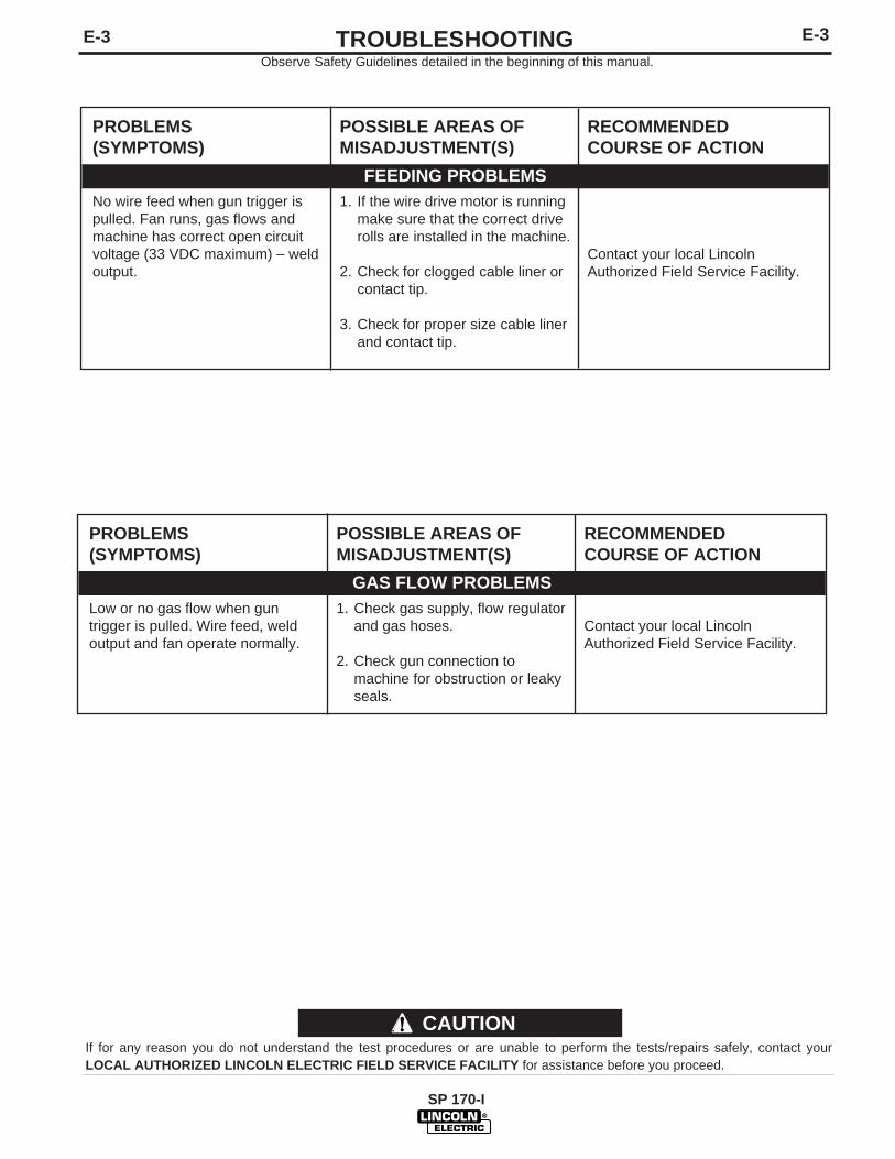
PROBLEMS(SYMPTOMS)
No wire feed when gun trigger ispulled. Fan runs, gas flows andmachine has correct open circuitvoltage (33 VDC maximum) – weldoutput.
POSSIBLE AREAS OFMISADJUSTMENT(S)
1. If the wire drive motor is runningmake sure that the correct driverolls are installed in the machine.
2. Check for clogged cable liner orcontact tip.
3. Check for proper size cable linerand contact tip.
RECOMMENDEDCOURSE OF ACTION
Contact your local LincolnAuthorized Field Service Facility.
FEEDING PROBLEMS
If for any reason you do not understand the test procedures or are unable to perform the tests/repairs safely, contact yourLOCAL AUTHORIZED LINCOLN ELECTRIC FIELD SERVICE FACILITY for assistance before you proceed.
CAUTION
PROBLEMS(SYMPTOMS)
Low or no gas flow when guntrigger is pulled. Wire feed, weldoutput and fan operate normally.
POSSIBLE AREAS OFMISADJUSTMENT(S)
1. Check gas supply, flow regulatorand gas hoses.
2. Check gun connection tomachine for obstruction or leakyseals.
RECOMMENDEDCOURSE OF ACTION
Contact your local LincolnAuthorized Field Service Facility.
GAS FLOW PROBLEMS
Observe Safety Guidelines detailed in the beginning of this manual.
E-4
SP-170-I
E-4 TROUBLESHOOTING
If for any reason you do not understand the test procedures or are unable to perform the tests/repairs safely, contact yourLOCAL AUTHORIZED LINCOLN ELECTRIC FIELD SERVICE FACILITY for assistance before you proceed.
CAUTION
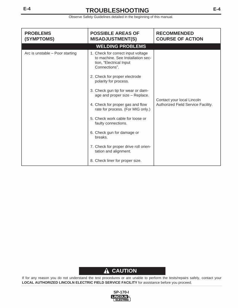
PROBLEMS(SYMPTOMS)
Arc is unstable – Poor starting
POSSIBLE AREAS OFMISADJUSTMENT(S)
1. Check for correct input voltageto machine. See Installation sec-tion, “Electrical InputConnections”.
2. Check for proper electrodepolarity for process.
3. Check gun tip for wear or dam-age and proper size – Replace.
4. Check for proper gas and flowrate for process. (For MIG only.)
5. Check work cable for loose orfaulty connections.
6. Check gun for damage orbreaks.
7. Check for proper drive roll orien-tation and alignment.
8. Check liner for proper size.
RECOMMENDEDCOURSE OF ACTION
Contact your local LincolnAuthorized Field Service Facility.
WELDING PROBLEMS
Observe Safety Guidelines detailed in the beginning of this manual.
SP-170-I
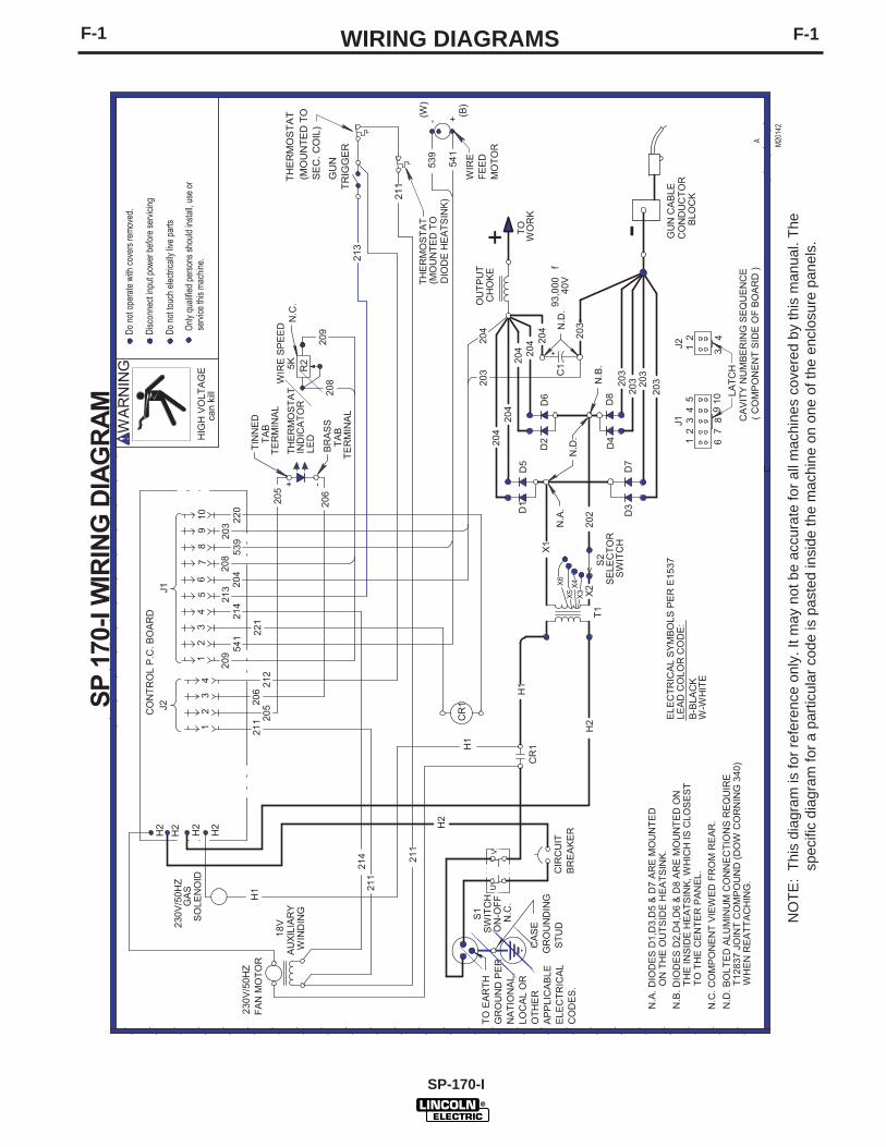
F-1F-1 WIRING DIAGRAMS
NO
TE:
This
dia
gram
is fo
r ref
eren
ce o
nly.
It m
ay n
ot b
e ac
cura
te fo
r all
mac
hine
s co
vere
d by
this
man
ual.
The
spec
ific
diag
ram
for a
par
ticul
ar c
ode
is p
aste
d in
side
the
mac
hine
on
one
of th
e en
clos
ure
pane
ls.
NOTES
SP 170-I
NOTES
SP 170-I
WARNING
AVISO DEPRECAUCION
ATTENTION
WARNUNG
ATENÇÃO
Spanish
French
German
Portuguese
Japanese
Chinese
Korean
Arabic
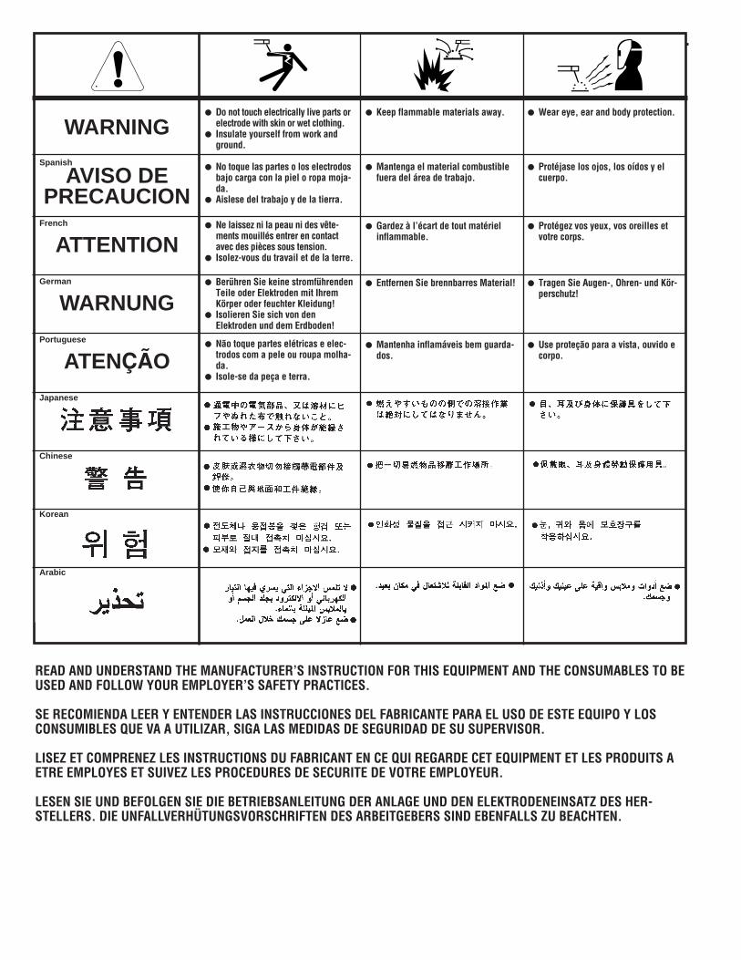
READ AND UNDERSTAND THE MANUFACTURER’S INSTRUCTION FOR THIS EQUIPMENT AND THE CONSUMABLES TO BEUSED AND FOLLOW YOUR EMPLOYER’S SAFETY PRACTICES.
SE RECOMIENDA LEER Y ENTENDER LAS INSTRUCCIONES DEL FABRICANTE PARA EL USO DE ESTE EQUIPO Y LOSCONSUMIBLES QUE VA A UTILIZAR, SIGA LAS MEDIDAS DE SEGURIDAD DE SU SUPERVISOR.
LISEZ ET COMPRENEZ LES INSTRUCTIONS DU FABRICANT EN CE QUI REGARDE CET EQUIPMENT ET LES PRODUITS AETRE EMPLOYES ET SUIVEZ LES PROCEDURES DE SECURITE DE VOTRE EMPLOYEUR.
LESEN SIE UND BEFOLGEN SIE DIE BETRIEBSANLEITUNG DER ANLAGE UND DEN ELEKTRODENEINSATZ DES HER-STELLERS. DIE UNFALLVERHÜTUNGSVORSCHRIFTEN DES ARBEITGEBERS SIND EBENFALLS ZU BEACHTEN.
● Do not touch electrically live parts orelectrode with skin or wet clothing.
● Insulate yourself from work andground.
● No toque las partes o los electrodosbajo carga con la piel o ropa moja-da.
● Aislese del trabajo y de la tierra.
● Ne laissez ni la peau ni des vête-ments mouillés entrer en contactavec des pièces sous tension.
● Isolez-vous du travail et de la terre.
● Berühren Sie keine stromführendenTeile oder Elektroden mit IhremKörper oder feuchter Kleidung!
● Isolieren Sie sich von denElektroden und dem Erdboden!
● Não toque partes elétricas e elec-trodos com a pele ou roupa molha-da.
● Isole-se da peça e terra.
● Keep flammable materials away.
● Mantenga el material combustiblefuera del área de trabajo.
● Gardez à l’écart de tout matérielinflammable.
● Entfernen Sie brennbarres Material!
● Mantenha inflamáveis bem guarda-dos.
● Wear eye, ear and body protection.
● Protéjase los ojos, los oídos y elcuerpo.
● Protégez vos yeux, vos oreilles etvotre corps.
● Tragen Sie Augen-, Ohren- und Kör-perschutz!
● Use proteção para a vista, ouvido ecorpo.
WARNING
AVISO DEPRECAUCION
ATTENTION
WARNUNG
ATENÇÃO
Spanish
French
German
Portuguese
Japanese
Chinese
Korean
Arabic
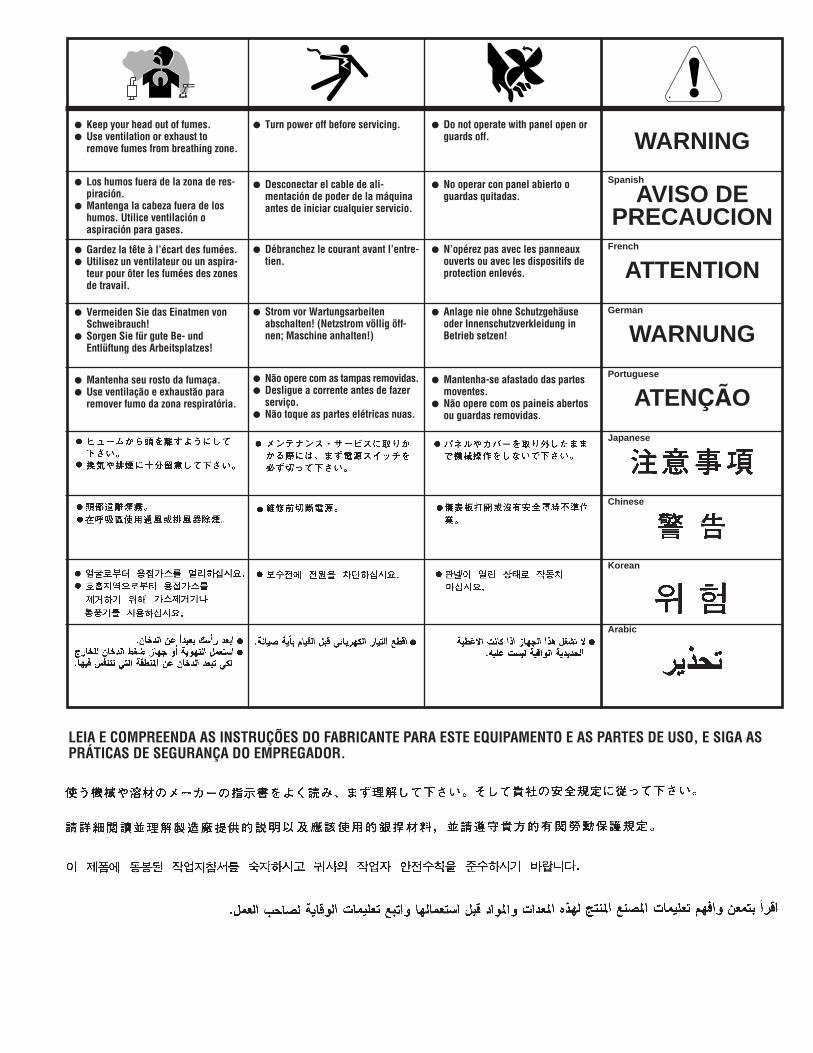
LEIA E COMPREENDA AS INSTRUÇÕES DO FABRICANTE PARA ESTE EQUIPAMENTO E AS PARTES DE USO, E SIGA ASPRÁTICAS DE SEGURANÇA DO EMPREGADOR.
● Keep your head out of fumes.● Use ventilation or exhaust to
remove fumes from breathing zone.
● Los humos fuera de la zona de res-piración.
● Mantenga la cabeza fuera de loshumos. Utilice ventilación oaspiración para gases.
● Gardez la tête à l’écart des fumées.● Utilisez un ventilateur ou un aspira-
teur pour ôter les fumées des zonesde travail.
● Vermeiden Sie das Einatmen vonSchweibrauch!
● Sorgen Sie für gute Be- undEntlüftung des Arbeitsplatzes!
● Mantenha seu rosto da fumaça.● Use ventilação e exhaustão para
remover fumo da zona respiratória.
● Turn power off before servicing.
● Desconectar el cable de ali-mentación de poder de la máquinaantes de iniciar cualquier servicio.
● Débranchez le courant avant l’entre-tien.
● Strom vor Wartungsarbeitenabschalten! (Netzstrom völlig öff-nen; Maschine anhalten!)
● Não opere com as tampas removidas.● Desligue a corrente antes de fazer
serviço.● Não toque as partes elétricas nuas.
● Do not operate with panel open orguards off.
● No operar con panel abierto oguardas quitadas.
● N’opérez pas avec les panneauxouverts ou avec les dispositifs deprotection enlevés.
● Anlage nie ohne Schutzgehäuseoder Innenschutzverkleidung inBetrieb setzen!
● Mantenha-se afastado das partesmoventes.
● Não opere com os paineis abertosou guardas removidas.
• Sales and Service through Subsidiaries and Distributors Worldwide •Cleveland, Ohio 44117-1199 U.S.A. TEL: 216.481.8100 FAX: 216.486.1751 WEB SITE: www.lincolnelectric.com
• World's Leader in Welding and Cutting Products •