9.4.1 General .................................................................................................................................. 26 9.4.2 Final Inspection ...................................................................................................................... 27 9.4.3 Test Verification .................................................................................................................... 27 9.4.4 System Performance ............................................................................................................ 27 9.4.5 Final Acceptance .................................................................................................................. 27
9.5 Warranty and Services ............................................................................................................ 27 9.5.1 General .................................................................................................................................. 27 9.5.2 Installation Warranty .......................................................................................................... 27
10 AUDIO VISUAL AND CONFERENCE ROOM STANDARDS ....................................... 28 10.1 Small Meeting Room ............................................................................................................... 28 10.2 Telehealth Rooms ..................................................................................................................... 28 10.3 Medium Sized Room ............................................................................................................... 28 10.4 Large Room .............................................................................................................................. 29
11 CABLE MANAGEMENT AND DESKTOP PLACEMENT GUIDELINES ........................... 30 11.1 Communication Room Guidelines ......................................................................................... 30 11.2 Desktop Guidelines ................................................................................................................. 30
• Communications cabling infrastructure specification for the Authorities Data and Telecommunications networks. • Cabling Management Guideline for Network Closets and Desktop Computers/Telephones • Audio Visual and Video Conferencing Standards
This document and any associated appendices are to be used by all staff, consultants, and contractors working with any of the Authorities IMIT infrastructure. Although this document will serve as a baseline specification for all current and future Authority facilities, the Authority reserves the right to alter or customize the specification as required. It is the intention of the specification and drawings to call for work to be finished, tested, commissioned and ready for operation.
It is the responsibility of the Prime Consultant, Design Engineer, Cabling Contractor, or other professional services involved to read this document in its entirety along with the Statement of Work, Request for Proposal, and any accompanying drawings and to identify any errors or omissions prior to tendering or submitting a quotation. Any apparatus, appliances, materials, or work not shown on the drawings, but mentioned in the specifications, or vice versa, or any incidental accessories necessary to make the work complete and perfect in all respects and ready for operation, even if not particularly specified, shall be furnished, delivered and installed. There will be no allowances for extras based on interpretation of the specifications or drawings.
Cabling Contractors that will be installing all low voltage CAT 5E/CAT6 systems at any Authority facility wired with AMP cabling or new construction must use employees that are certified to install AMP NETCONNECT Cabling Systems in compliance with ANSI/TIA-568.1 The Authority specific requirements are that installers are TYCO AMP NETCONNECT level 1 and 2 certified, and that an AMP NETCONNECT level 3 employee supervise and approve all installations.
Cabling contractors that will be installing all low voltage CAT 5 systems at any existing Authority facility wired with an Integrated Building Distribution Network (IBDN) using Belden Nordx cabling must use employees that are Belden Certified System Installers.
1.2 Scope This standards and specifications document applies to the data and telecommunications cabling system and overall IMIT Infrastructure at all facilities owned or operated by the Authority, unless otherwise noted.
1.3 Work Included Work shall be in accordance with the drawings and specifications and their intent. Work shall include all: materials, labour, tools, equipment and services required for the construction, installation and putting into regular operation the complete communication system as shown on the drawings and as described and specified in this and accompanying sections
1 A complete list of current contractors can be found at http://www.ampnetconnect.com/search_contractor.asp?country=CA&state=BC&x=12&y=8
1.4 Reference Standards All materials, workmanship and/or installation practices and activity shall meet or exceed the following reference standards:
• ANSI/TIA/EIA-569 (CSA T530) ) – Commercial Building Standard for Telecommunications Pathways • ANSI/TIA/EIA-607 (CSA T527) – Commercial Building Grounding and Bonding Requirements • ANSI/TIA/EIA-606 (CSA T528) – Administration Standard for the Telecommunications Infrastructure • ANSI/TIA/EIA-568-C.x – Commercial Building Telecommunications Cabling Standard • ANSI/TIA/EIA-1179-2010 Healthcare Facility Telecommunications Cabling Standard • ANSI/TIA/EIA TSB-67 – Transmission Performance Specifications for Field Testing • Tyco Electronics AMP System Certification • BICSI Telecommunications Distribution Methods Manual (TDMM) • BICSI 004-2012 Information Technology Systems Design and Implementation Best Practices for Healthcare
Institutions and Facilities • TIA TSB-162- Telecommunications Cabling Guidelines for Wireless Access Points • CEC part 1 C22.1 • British Columbia Building Code • UL Cable Certification Program • UL Testing Bulletin
This document shall supersede the above if a conflict exists. Municipal, provincial, and federal laws, bylaws, regulations, and codes shall supersede the above and this document in cases of conflict. Any conflicts must be brought to the attention of the maintainer of this document for resolution. In the case of conflicts or discrepancies the more stringent Code shall apply. In case of Hospital installations ANSI/TIA/EIA-1179-2010 takes precedence.
The Prime Consultant, Design Engineer, Cabling Contractor, or other professional services is responsible to determine the most current release of the above documents and adhere to such release of the documents. Any changes or alteration shall be reissued as a new version and supersede the previous. The Authority will endeavor to provide the most current version to all parties above. Verification of the latest release can be obtained by contacting the Authorities IMIT Facilities Project Coordinator via email at [email protected]
I.M.I.T. Infrastructure Specifications
Page 6
2 DEMOLITION REQUIREMENTS
2.1 Demolition
Proper coordination for the shut-off of utility services and control measures for dust and noise must occur prior to commencement of any demolition work. Considerations must be given to on-going services and activities in adjacent areas. In confined areas of selective demolition, install and maintain dust and noise control barriers to keep dirt, dust, and noise from being transmitted to adjacent areas. Remove these protection measures after demolition operations are completed.
Completely remove all equipment noted on the drawings for removal including all associated devices, controls, conduit, wiring, etc. Remove all exposed conduit and wiring back to the panel from which it is served. Unless otherwise noted, the Contractor shall fill and patch all wall, floor, and ceiling openings resulting from this demolition work with materials and finishes identical to adjacent materials and finished.
Unless otherwise noted, remove all wiring devices, fixtures, controls, circuitry (conduit and wiring), etc., made obsolete by the demolition within or around the building.
The Contractor shall relocate all existing piping, circuitry (conduit and wiring), ductwork, etc., which impedes the installation of new materials and equipment, unless otherwise noted.
All demolition which involves the removal or disturbance of Asbestos Containing fire proofing, finish material, insulation or other asbestos containing material must be approved by the Authority.
2.2 Disposal
The Contractor shall remove all generated trash, recyclables and debris at their expense. The Contractor may not place this trash and debris in any Authority facility dumpsters. The Authority, shall retain the right to direct the disposal of salvageable equipment and materials. No equipment is given to the Contractor unless specifically listed in the job specifications prior to contract award. The Contractor shall deliver any surplus equipment to a site designated by the Authority and return a receipt for the equipment to the Authority
I.M.I.T. Infrastructure Specifications
Page 7
3 TELECOMMUNICATIONS SYSTEM REQUIREMENTS
3.1 Basic Communications Requirements This section of the specification is for the supply, installation, testing and certification of the communications cabling requirements. This specification must be followed unless explicit written consent is received from the manager (or designate) of NTS. All new EF, TR, TC that do not have existing data cabling require a Category 6 distribution system. Existing EF, TR, TC, with CAT 5/5E that requires MACs may be installed with the Category 5E distribution system. The voice and data Category 5E/6 distribution system is to share faceplate outlets, conduits, cable trays, raceways and a certified category 5E/6 patch panel system. Every voice device run and data device run is to be identical in configuration and electrical characteristics. In other words, a voice device run could be used for either voice or data, as need dictates. All data and voice runs are to terminate on a universal patch panel system which will permit assignment from the data hardware by the use of labelled patch cords. A voice tie cable will be used to provide a cross-connect between the patch panels and existing BIX connection blocks. For MAC work related to legacy voice installations, voice cable may terminate on a universal BIX punch block system which will permit assignment from the voice hardware by the use of labelled patch cords.
The “home run” device runs are to consist of three white AMP Category 5E/6 UTP, 4 pair, 24/23 AWG CMR / CMP rated cables based on jurisdictional / municipal codes. Specialized device runs or incidental voice lines requiring alternative design will be specified in accompanying documentation. Each communication outlet will have three permanent links as defined in EIA/TIA 568-C, two designated for Data and one for Voice.
Designated VOIP Sites will have two data links per communications outlet. The four port outlets will have two spare ports for future expansion, except in locations specified otherwise. All outlets will use four port face plates unless otherwise specified.
The cabling system must meet or exceed Category 5E/6 performance defined in EIA/TIA 568-C and provide a 25 year system performance certification from an AMP NETCONNECT single channel source manufacturer. Multi or mixed vendor solutions will NOT be considered.
3.2 Administration Requirements The specifications shall be considered as a integral part of the drawings which accompany them, neither of which shall be used alone, and all services, materials or apparatus, omitted from one but which is mentioned, shown or reasonably implied in the other shall be considered as properly and sufficiently specified and shall therefore be supplied and installed.
The location of various items indicated on the drawings is approximate except where specifically mentioned. It shall be understood drawings are generally diagrammatic and are only intended to indicate the scope and general arrangement of work and that the locations shown are subject to relocation within two meters at no additional costs to IHA to accommodate varying construction conditions. Onsite measurements must be taken to ensure components will fit within specified geographic building dimensions while meeting all codes and regulations.
The entire electrical installation shall comply with the most recent versions of the following codes, standards, and policies: All municipal By-laws, Provincial Codes, The national Building Code, The Canadian Electrical Code, Canadian Labour Code, and the National Fire Code. In the case of conflict or discrepancy the more stringent code shall apply.
ll necessary permits, licences, inspections and related fees to the above are the responsibility of the contractor.
I.M.I.T. Infrastructure Specifications
Page 8
3.3 Contractor Responsibilities The contractor responsibilities in the execution of specification and work are:
• Responsible for the work until its substantial performance and replace any of the same that may be damaged, lost or stolen without additional costs to IH.
• Work shall be arranged in co-operation with the other subcontractors in such a manner as not to interfere. • Protect finished and unfinished work of the building from damage resulting from the carrying out of the work. Protect
floors and walls, where necessary. Repair all damages to floor surfaces resulting from the execution of this work, without additional charge.
• On completion of work and before acceptance ensure all exposed surfaces of communications equipment are cleaned.
• Before finalizing the contract price a site visit is mandatory to report any condition or logistical problem that may prevent them performing the work as specified
• Promptly advise of any work functions that appear in conflict with local authorities and work not included in work contract. All work and materials shall be in full accordance with CSA codes, provincial and local inspection authorities having jurisdiction. All the above shall be considered as a minimum requirement and be taken into account. The requirements as designed shall not be reduced as a result of the above and no extra charges will be accepted.
• Make no changes to the design intent without written authority. The contractor shall give IH 48 hrs notice in advance of any field reviews required.
• Ensure that equipment does not transmit noise and/or vibration to other parts of the building as a result of poor installation practice.
• The contractor shall keep a competent, (qualified journeyman) foreman on the job site during the construction, testing and acceptance period. The above will not be changed from the project unless satisfactory reasons are given in writing to IHA.
• Contractors are responsible that all closets, telecommunications rooms are secure while performing the work. The above must also be left in a secure state after use and the contractor will be responsible for all damages and costs as result of improper use of the facility.
• During the course of the project the site must be kept clean and tidy by the contractor. Additionally the building and site must be cleaned to a condition acceptable to IHA before final completion.
I.M.I.T. Infrastructure Specifications
Page 9
4 COMMUNICATION ROOM SPECIFICATIONS
4.1 Entrance Facility (EF) A. The EF consists of the telecommunications service entrance to the building, including the entrance point
through the building wall, and continuing to the entrance room or space. The EF of each new building is the location where campus cables (inter-building) and intra-building services interconnect. The space shall be identified on the drawings. The demarcation point between service providers and IHA premise cabling is generally located here.
B. All carriers and telecommunications providers involved in providing service to the building shall be contacted to establish their requirements and explore alternatives for delivering service. The location of other utilities, such as electrical, water, gas, and sewer shall be considered in the site selection of the telecommunication entrance facility.
C. A service entrance pathway shall be provided. The basic methods for provisioning are underground, buried, and aerial pathways.
D. Entrance facility telecommunication rooms shall have a minimum of two (2) feed conduits of 101.6 mm (4”)
E. In determining the total number of pathways required the planner shall consider the following:
a) Type and use of building b) Growth c) Difficulty of adding pathways in the future d) Alternate entrance e) Type and size of cables likely to be installed
F. The entrance room or space is the component of the EF that provides space for the termination of the
entrance backbone cable. In accordance with electrical code the entrance or outside building cable shall be terminated and protected on a listed primary protector within 15m. (50 ft.) of entering the building. Where telecommunications equipment (e.g. PBX) is located in the entrance room or space, the entire room or space shall meet the requirements for an equipment room as specified in Section 8 of TIA/EIA-569-A. If the network interface devices and telecommunication equipment are required in the entrance room, additional space will be needed.
G. The decision whether a room or open area is provided shall be based on security, quantity, type of termination and equipment, size of building and physical location within the building. For buildings exceeding 6096m (20,000 sq. ft.) usable floor space, an enclosed room should be provided.
I.M.I.T. Infrastructure Specifications
Page 10
I. In buildings (with up to 30480 sq m. (100,000 sq. ft.)) of usable floor space, wall mounted terminating hardware may be suitable. Buildings of larger floor area may require freestanding frames for cable termination. Tables 8.3-1 and 8.3-2 of TIA/EIA-569-C specify the space for all telecommunications equipment and associated cross-connections based on a 2.44 m. (8 ft.) wall or on freestanding racks.
J. Listed below are some additional provisions for entrance facilities:
a) A minimum of two walls shall be covered with rigidly fixed (3/4 trade size) A-C plywood, void free, 2.44m (8ft) high, capable of supporting attached equipment. Plywood shall be either fire rated or covered with two coats of fire retardant paint.
b) Lighting shall be a minimum of 50 foot candles measured 1m (3ft). above the finished floor. c) False ceiling shall not be provided. d) The access door shall be a minimum of 1m (36in) wide and 2m (80in) high and shall be fitted with a
lock. The brand of said lock shall be provided by IH and the lock must be keyed in accordance with supplied instructions. This door may also be accessible via card lock and secure access.
e) Floors, walls and ceiling shall be treated to eliminate dust. Finishes shall be light in color to enhance room lighting.
f) Electrical: A minimum of two dedicated 30A, 120V AC L530R electrical outlets, each on separate circuits, shall be provided for equipment power if required as part of the site-specific specifications. Consideration should be given to identifying those outlets dedicated to telecommunications equipment. In addition, convenience duplex outlets on a separate 20A 120V AC circuit shall be placed at 1.83m (6ft) intervals around the perimeter walls, at a height of 15.2cm (6in) above the floor. If emergency power is available, consideration shall be given to automatic power backup.
g) If an emergency power source is available in the building at least one of the duplex outlets must be so supplied and marked as such.
h) Access shall be made available to the independent telecommunications grounding system specified by ANSI/TIA/EIA 607.
i) TIA/EIA-569-A contains fire stopping, sprinkler requirements, miscellaneous pathways, and telecommunications recommendations of separation from less than 480V power lines.
j) HVAC must maintain a continuous and dedicated environmental control with a temperature range of 20C to 25C and a humidity range of 40% to 55% relative humidity.
K. The entrance facility will house communications electronics which shall be installed and activated by the Authority.
4.2 Main Cross connect (MC) Copper and fiber backbone cables extend from the MC to the telecommunication room as shown on the drawings. The MC also serves as a telecommunications room for services to the work areas.
The MC includes termination hardware, equipment racks, patch panels, cable management hardware, and network electronics. The MC shall house the telecommunications main grounding busbar (TMGB). The bonding backbone cables shall extend from the TMGB to each of the telecommunications room as shown on the drawings.
I.M.I.T. Infrastructure Specifications
Page 11
4.3 Telecommunications Rooms (TR) Telecommunications Rooms (TR) and closets (TC) provide many different functions for the cabling systems and are often treated as a distinct sub-system within the hierarchical cabling system. The TR is the location for cross-connecting the backbone cable and horizontal station cable .Horizontal cables of all recognized hardware. Similarly, recognized types of backbone cable are also terminated in the TR on compatible connecting hardware.
The cross-connection of horizontal and backbone cable using jumper or patch cords allows flexible connectivity when extending various services to telecommunications outlet/connectors. Connecting hardware, jumpers, and patch cords used for this purpose are collectively referred to as “horizontal cross-connect”. Patch cords used for horizontal cross-connect must be of the same type (IE CAT 5E or CAT 6) as the horizontal cabling to which they will be connected. The TR may also contain the IC or the MC connections for different portions of the backbone cabling system.
Sometimes backbone to backbone cross-connections in the TR are used to tie different TR’s together in a ring, bus, or tree configuration. Equipment cables that consolidate several ports on a single connector shall be terminated on dedicated connecting hardware. Equipment cables that extend a single port appearance may either be permanently connected or interconnected directly to horizontal or backbone termination. Direct interconnections reduce the number of connections required to configure a link but may reduce flexibility.
The TR houses a telecommunications grounding busbar (TGB). The TR includes equipment racks, cable management hardware, termination hardware and labelling.
TR shall have a minimum fed conduit of 101.6mm (4in). Telecommunication rooms shall be dedicated facilities and not be co-located with any other service (eg: Plumbing, electrical, storage). The TR includes equipment racks, cable management hardware, termination hardware and labelling. The TR shall be equipped with electrical power, plywood backboard, lighting, floor covering, paint, and HVAC by Others.
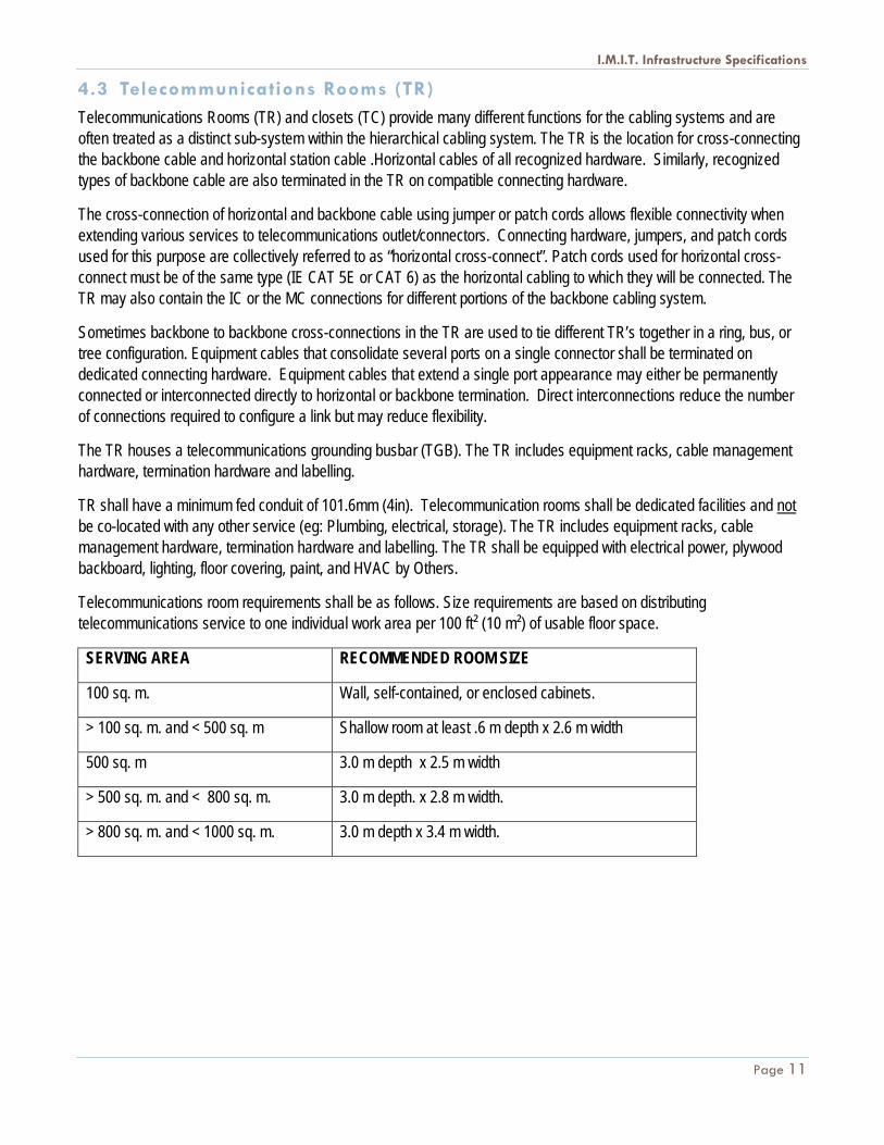
Telecommunications room requirements shall be as follows. Size requirements are based on distributing telecommunications service to one individual work area per 100 ft² (10 m²) of usable floor space.
SERVING AREA RECOMMENDED ROOM SIZE
100 sq. m. Wall, self-contained, or enclosed cabinets.
> 100 sq. m. and < 500 sq. m Shallow room at least .6 m depth x 2.6 m width
500 sq. m 3.0 m depth x 2.5 m width
> 500 sq. m. and < 800 sq. m. 3.0 m depth. x 2.8 m width.
> 800 sq. m. and < 1000 sq. m. 3.0 m depth x 3.4 m width.
I.M.I.T. Infrastructure Specifications
Page 12
The additional provisions for IHA entrance facilities also apply to telecommunication rooms and closets. Further provisions to be considered are as follows:
• TR or TC should not be used as a passageway to other equipment rooms, nor should they share space with fire reporting equipment, alarm systems, electrical panel boards, power transformers, plumbing, storage, custodial equipment or any other function which would require access for reasons other than telecommunications maintenance.
• TC should be centrally located (both vertically and horizontally) within the building area served. TR and TC should be stacked horizontally on multi-floor buildings where possible. Although BICSI standards recommend a separate wiring closet for each floor level, every attempt should be made to maximize the area served from the primary wiring closet in order to minimize the cost of telecommunications wiring infrastructure equipment and space.
• TC should be accessible from a common hallway. • TC should be located in a low traffic area. • TC should not be located near office locations. • TC must not be located in a sterile core
• The maximum wiring run from the TR/TC to the most distant data outlet served from the room/closet can not exceed 90m (295ft) The TR/TC will be the origination point for wiring to all communications outlets within the area served.
• Where TC serve areas on more than one floor, the design process should recognize the need to incorporate appropriate paths of travel for the raceway systems which will be required to carry the telecommunications wiring between the floors.
5 BACKBONE CABLING REQUIREMENTS
5.1 General Backbone Requirements The function of the backbone cabling is to provide interconnections between telecommunications rooms, equipment rooms, and entrance facilities. In accordance with TIA/EIA-568-C the backbone cabling consists of the backbone cables, intermediate and main cross-connects, mechanical termination, and patch cords or jumpers used for backbone to backbone cross-connection.
• Backbone cables shall be installed separately from horizontal distribution cables. • Where cables are housed in EMT conduits, the backbone and horizontal cables shall be installed in
separate EMT conduits or in separate HDPEI within EMT conduits. • Where cables are installed in an air return plenum as required by code, the cable shall be installed in EMT
conduit, or plenum cable shall be installed in a corrugated plenum rated HDPEI to provide protection to the cable.
• Where backbone cables and distribution cables are installed in a cable tray or wire way, backbone cables shall be installed first and bundled separately from the horizontal distribution cables. If the backbone cable is fiber, the fiber must be installed inside corrugated HDPEI, and the HDPEI is to be attached to the outer or under side of the cable tray.
I.M.I.T. Infrastructure Specifications
Page 13
• In accordance with TIA/EIA-568-C the backbone cabling consists of the backbone cables, intermediate and main cross-connects, mechanical termination, and patch cords or jumpers used for backbone to backbone cross-connection.
• Backbone cabling also includes cabling between buildings. During each planning period, growth and changes in service requirements should be accommodated without installation of additional cabling.
• When a cable enters or exits a junction or pull box or other such enclosure the appropriate connector, grommet, or bushing needs to be used.
• ANSI/TIA/EIA-569-A specifies separation of the backbone cabling pathways from sources of EMI. Grounding of all metallic shields shall also be made to the main telecommunication ground.
• Consult TIA/EIA-569-C for pathway and floor penetration and conduit stub heights for all topologies. • The backbone distribution system shall follow the conventional hierarchical extended star topology
• There shall be no more than two hierarchical levels of cross-connects in the backbone cabling. From the horizontal cross-connect, no more than one cross-connect shall be passed through to reach the main cross-connect. Therefore, interconnections between any two horizontal cross-connects shall pass through three or fewer cross-connects. Only a single cross-connect shall be passed through to reach the main cross-connect. (See IHA Backbone Hierarchical Star Topology Diagram)
• If cable needs to go through a wall, be it drywall, concrete, wood or other, and an existing pathway does not exist, the created pathway must use electrical conduit as a sleeve with EMT connectors with nylon throats at each end of the conduit. Poking a hole in the wall and running the cable through is not acceptable. All penetrations through fire rated building structures (walls and floors) shall be sealed with an appropriate firestop system as per section 5.2.
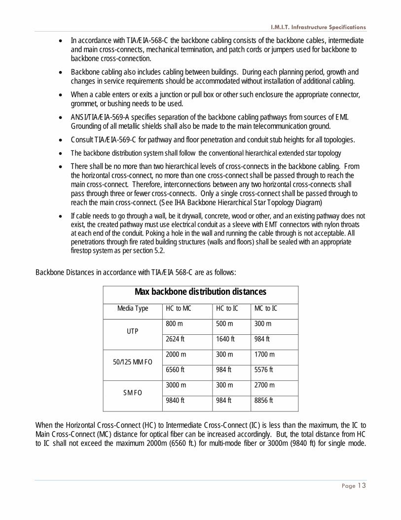
Backbone Distances in accordance with TIA/EIA 568-C are as follows:
Max backbone distribution distances
Media Type HC to MC HC to IC MC to IC
UTP 800 m 500 m 300 m
2624 ft 1640 ft 984 ft
50/125 MM FO 2000 m 300 m 1700 m
6560 ft 984 ft 5576 ft
SM FO 3000 m 300 m 2700 m
9840 ft 984 ft 8856 ft
When the Horizontal Cross-Connect (HC) to Intermediate Cross-Connect (IC) is less than the maximum, the IC to Main Cross-Connect (MC) distance for optical fiber can be increased accordingly. But, the total distance from HC to IC shall not exceed the maximum 2000m (6560 ft.) for multi-mode fiber or 3000m (9840 ft) for single mode.
I.M.I.T. Infrastructure Specifications
Page 14
When the HC to IC distance is less than the maximum, the IC to MC distance for UTP cabling can be increased accordingly but the total distance from the HC to the MC shall not exceed the maximum of 800m (2624 ft.)
5.2 Voice Backbone Requirements 1. Voice backbone cabling shall be AMP 24 AWG, 100-pair UTP, CMR or FT4 rated, with a gray PVC jacket.
Cable shall be third party verified to comply with TIA Category 3 requirements. 50-pair or 25-pair UTP may be used if approved. A coupled bonding conductor will be installed within the riser bundle and bonded and grounded at each end.
2. Voice backbone cables shall be terminated in BIX mount panels in a Cross-connect Wall Mount Layout using the 25-pair color code method. The color refers to the insulation covering each conductor. The first group (tip) of colors is, in order: white, red, black, yellow, violet. The second group (ring) of colors is, in order: blue, orange, green, brown, slate. Cable assemblies consisting of more than 25 pairs shall have binder groups consisting of 25 pairs with a colour coded wrapping. For the general layout rules the following parameters should be observed:
• A minimum of 20 cm from ceiling • A minimum of 20 cm from wall or equipment • A minimum of 15.25 cm between Frames
3. The quantity of UTP cable requirements. As a guide, three (3) pairs of category 3 UTP should be provided between the main cross-connect and each telecommunications closet for each work area planned to be served by the closet. For example, if one work area is planned per 10 square metres of floor space and the closet serves 500 square metres, 150 pairs (50 work areas x 3 pairs per work area) should be provided.
I.M.I.T. Infrastructure Specifications
Page 15
5.3 Data Backbone Requirements Twelve strand fiber optic cables shall be utilized to provide backbone connectivity between the Data MC and each TR. (Six strand can be used if approved). The optical fiber cable shall be AMP XG OM3 Multimode 50/125 µm, all-dielectric, and shall consist of one unit that contains twelve tight-buffered 850nm laser-optimized 50/125 µm fibers surrounded by aramid strength members and a PVC jacket.
The cable shall have a UL rating of OFNR (Riser) or will meet the requirements of FT4 as per CEC rule 2-126. The outside diameter of each unit shall be 6.2 mm making the overall cable dimensions 7.2 mm x 13.4 mm. The cable shall provide a maximum attenuation of 3.5 dB/km @ 850 nm and 1.5 dB/km @ 1300 nm. The bandwidth of the cable shall be 1500 MHz/km @ 850 nm and 500 MHz/km @ 1300 nm. Both ends of the cable will be terminated to LC-LC connectors. Each fiber optic cable shall be terminated in the Data MC and TR’s in black 24 port rack mount enclosures providing protection to the terminated fibers. All strands shall be terminated. All exposed fiber in telecommunications pathways shall be protected with riser rated corrugated High Density Polyethylene Innerduct (HDPEI).
• HDPEI must
• Meet testing requirements for CSA C22.2 No.262 • Meet or exceed the requirements for FT-4 in accordance with the National Building Code of
Canada
All other exposed fiber shall be protected between the point where the EMT conduit enters the communications room, and the fiber enters the terminating enclosure, including a service loop, using HDPEI. The HDPEI must be securely fastened to the wall or vertical cable management system in order to ensure it is not hanging down in the middle of the closet.
6 HORIZONTAL CABLING REQUIREMENTS
6.1 Telecommunications Outlets Each outlet location will be three Category 5E/6 cables unless otherwise specified. The cables shall be terminated on 8-position, 8-conductor Category 5E/6 Universal jack for Data and voice to the T568A wiring code. The outlet plates, unless otherwise noted, shall be 4 outlet, mounted to single gang boxes, mounting bracket (Arlington Industries LV1 or similar), surface mount boxes, and/or floor monuments (3rd party) as required.
Horizontal cabling shall be AMP NETCONNECT, Category 5E/6, 24/23 AWG, 4-pair UTP, UL/NEC/CSA CMR rated, with a white PVC jacket. Cable jacketing shall be lead-free. Cable shall meet the performance requirements outlined in EIA/TIA 568-C in addition to all other standard Category 5E/6 performance requirements.
Category 5E/6 Cabling –plenum
Horizontal cabling shall be AMP NETCONNECT, Category 5E/6, 24/23 AWG, 4-pair UTP, UL/NEC/CSA CMP or CSA equal rated, with a white plenum-rated PVC jacket. Individual conductors shall be 100% FEP insulated. Cable jacketing
I.M.I.T. Infrastructure Specifications
Page 16
shall be lead-free. Cable shall meet the performance requirements as outlined in EIA/TIA 568-C in addition to all other standard Category 5E/6 performance requirements.
6.3 Modular Jacks and Face Plates All modular jacks shall be wired to the T568A wiring pattern. Modular jacks shall be terminated using IDC connections colour coded for both T568A and T568B wiring. Modular jacks shall be UL Listed under file number E81956 or CSA equivalent.
Category 5E/6 modular (data) jacks shall be unkeyed 4-pair and shall meet the performance requirements outlined in EIA/TIA 568-C in addition to all other standard Category 5E/6 performance requirements.
All Office and Room Outlets shall use white AMP, 4-port, single gang, flush faceplates constructed of ABS moulding compound and be 4.53” X 2.77” X .60” in size. Each faceplate shall contain three Category 5E/6 jacks as noted in 3.1 above (unless the site is a designated VOIP site then only two cables will be run and terminated in each outlet, with black jacks). Each port shall be individually labelled above the port with white machine printed label tape, applied horizontally, to indicate its function, as indicated in section 6.1.2. The faceplates shall be mounted to in-wall single gang boxes. The faceplate specified is AMP NETCONNECT part number 1479446-3 or AMP's latest replacement product.
Where new cable is added to an existing telecommunications outlet, the faceplate and all existing jacks shall be replaced to bring the entire outlet up to the current AMP SL series specifications.
The following shall be maintained during Telecommunications Outlet Installation:
• Cables shall be coiled in the in-wall or surface-mount boxes if adequate space is present to house the cable coil without exceeding the manufacturer’s bend radius.
• In hollow wall installations where box-eliminators are used, excess wire can be stored in the wall.
• No more than 12” of slack shall be stored in an in-wall box, modular furniture raceway, or insulated walls. Excess slack may be neatly stored in the ceiling above each drop location in a figure-eight coil when there is not enough space present in the outlet box to store slack cable. Coiled slack in the ceiling space should not exceed 2m of cable.
• Cables shall be dressed and terminated in accordance with the recommendations made in the TIA/EIA-568-C document, manufacturer’s recommendations and/or best industry practices.
• Pair untwist at the termination shall not exceed one-quarter inch for Category 5E/6 connecting hardware. • Bend radius of the UTP cable in the termination area shall not be less than 4 times the outside diameter of the
cable as per the TIA/EIA 568-C standard. • The cable jacket shall be maintained as close as possible to the termination point. Where cables are terminated
on AMP SL series jacks, the cable jacket must be fully inserted into the strain relief. • Black data/voice jacks shall occupy the top position(s) on the faceplate. Data jacks in horizontally oriented
faceplates shall occupy the left-most position(s).
I.M.I.T. Infrastructure Specifications
Page 17
• The IHA colour coding for jacks to identify system usage is as follows:
CABLELABEL
JACK COLOUR USAGE
TERMINATIONPOINT
D Black Data/Voice Applications PPW Green Wireless Connection Outlet (POE) PPN Yellow Nurse Call (Yellow Sheathed Cable) NC BRCP Red Patient Monitoring PPV White Voice (Legacy MAC work only) BIXCC Violet IP Security/CCTV - Green Cable Sep. PP
Horizontal distribution cable for data circuits shall be Category 5E/6, 4-pair unshielded twisted pair, CMP or CMR rated cable as required. Horizontal distribution cable for voice circuits shall be as defined above. Quantities of cables to each outlet type shall be in accordance with the definitions provided in Section 3.1.1 above. In addition the following practices should be maintained in installation:
• Cable shall be installed in accordance with manufacturer’s recommendations and best industry practices. • Horizontal pathways, raceways and trays, shall not be filled to greater than 40% of fill capacity during initial
installation. • Conduit shall not be filled to greater that 40% of fill capacity during initial installation. • Cable trays shall be galvanized steel, ladder type, barriered and house only data, wireless, patient monitoring,
video, and nurse call cabling with soft 90 degree bends as per TIA/EIA cabling standards. All nurse call cabling that leaves the cable tray must be protected in conduit stubbed up from the cable tray to the outlet box.
• Cables shall be installed in continuous lengths from origin to destination (no splices) unless specifically addressed in this document.
• Consolidation points are not permitted except by written authority. • The cable’s minimum bend radius and maximum pulling tension shall not be exceeded.
• When a cable enters or exits a junction or pull box or other such enclosure the appropriate connector, grommet, square cornered mud ring or bushing shall be used.
• If a J-hook or trapeze system is used to support cable bundles all horizontal cables shall be supported at a maximum of four-foot intervals. At no point shall cable(s) rest on acoustic ceiling grids or panels.
• Horizontal distribution cables shall be bundled in groups of no greater than 40 cables. Cable bundle quantities in excess of 40 cables may cause deformation of the bottom cables within the bundle, and increase the chances of alien crosstalk.
• Cable shall be installed above fire-sprinkler and systems and shall not be attached to the system or any ancillary equipment or hardware.
• The cabling system and support hardware shall be installed so that it does not obscure any valves, fire alarm conduit, boxes, or other control devices.
• Cables shall not be attached to ceiling grid or lighting support wires. Where light supports for drop cable legs are required, the contractor shall install clips to support the cabling.
• Any cable damaged or exceeding recommended installation parameters during installation shall be replaced by the contractor prior to final acceptance at no cost to the Owner.
I.M.I.T. Infrastructure Specifications
Page 18
• Cables shall be identified by a self-adhesive label in accordance with the System Documentation Section of this specification.
• 4-pair UTP cable shall be installed so that there are no bends less than four times the cables outside diameter (4 X cable O.D.) at any point in the run as outlined in EIA/TIA 568-C.
• Pulling tension on 4-pair UTP cables shall not exceed 25-pounds for a single cable or cable bundle as outlined in EIA/TIA 568-C
• Cables run through conduit will not pass through more than two 90 degree corners (or equivalent) without the use of an intermediate pull box as outlined in EIA/TIA 568-C.
• If cable needs to go through a wall, be it drywall, concrete, wood or other, and an existing pathway does not exist, the created pathway must use electrical conduit as a sleeve with EMT connectors with nylon throats at each end of the conduit. Poking a hole in the wall and running the cable through is not acceptable. All penetrations through fire rated building structures (walls and floors) shall be sealed with an appropriate firestop system as per section 5.2.
• If cable is to be terminated in an open office location with modular furniture and termination within a wall is not a viable option, then the cables are to terminate within PAC poles, not the modular furniture.
6.4 Wireless For Wireless Connection Outlet locations:
• Provide one (1) Category 5E/6 cable, terminated per section 4.3.3 using green jacks. • Provide 5m slack for each cable, at the field end, coiled neatly, suspended in the ceiling space with proper
support and cable management. Coil radius must be within acceptable bend radius for the cable as per EIA/TIA 568-C.
• Support cables with Velcro wraps or equivalent. Tie-wraps are not to be used. • As of July 2013, the current wireless access point standard is Cisco.
6.5 Nurse Call • All Nurse Call installations will be installed using yellow sheathed AMP Category 5E UTP Cable, 4 pair, 24 AWG
CMR rated based on jurisdictional / municipal codes. • VoIP terminals that are connected directly to the IHA data switch shall use the predominant cabling standard in
the closet that the terminal is terminating to whether it is CAT5E or CAT6. • All cables will be routed in a cable tray and stubbed up conduit from the cable tray to the device location. • Cables must not be buried amongst new or existing data/voice cables in pathways. • Marquees are to be seismically restrained and mounted on appropriate T-Bar hangers. • As of July 2013, the current Nurse Call standard is the Rauland Responder 5.
6.6 Security and Closed Circuit TV (CCTV) • All security and CCTV cabling must follow the same low-voltage cabling specifications outlined in this document
for network cabling. eg: J-hooks, firestopping, etc. • Security cabling sharing pathways with network cabling must not compromise the integrity of existing network
cabling. It is not acceptable to bundle security cabling to network cabling using tie wraps. • Cabling for IP-CCTV and IP-Security systems shall be designed according to the standards and best practices
outlined in this document. Copper cables should run to a closet on the same floor as the work area. Closets
I.M.I.T. Infrastructure Specifications
Page 19
shall be laid out so that no copper cable will exceed 95m, and fiber optic cable will be used to connect all closets to a central or core closet.
• All interconnections must be made with certified patch cables. Under no circumstances shall any cables be manually terminated with modular plugs.
• As with all network cabling, as-built drawings and certification results must be provided by the cabling vendor. • All new IP-Security/CCTV installations shall be installed using green sheathed AMP Category 5E or Cat6 UTP
Cable, 4 pair, 24 AWG CMR rated based on jurisdictional / municipal codes. (If AMP is not available, Belden, Superior Essex, or another suitably rated green sheathed cable will suffice)
• Terminate at the head end to violet AMP SL series 8P8C modular jacks mounted in 48 port unloaded patch panels in the nearest data closet.
• Terminate at the field end to violet AMP SL series 8P8C modular jacks mounted in a 4 port faceplate as per section 4.3.3. Blanks must be used for spare ports in each outlet. For jacks terminated in the ceiling space, such as those for CCTV cameras, surface mount jacks may be used.
• In situations where IP-Security/CCTV cabling will share a common infrastructure or share rack space with IHA cabling or network equipment, the NTS department must be consulted during the planning phase.
6.7 Patch and Interconnection Cabling Requirements
6.7.1 Horizontal Data Cross-Connect
The horizontal cross-connect for data circuits shall consist of patch cords from the horizontal Category 5E/6 termination panels to the network equipment within the same or adjacent racks. The horizontal data cross-connect shall be contained in suitably sized 19” racks. All equipment racks shall be augmented with horizontal and vertical management hardware, to properly dress horizontal cables and patch cords.
• Horizontal cable managers must be installed above and below every 48 port patch panel. AMP Netconnect part no. 1933533-1 or Panduit NM2. Authority preference is Panduit NM2.
• Vertical cable managers must be installed on both sides of rack. AMP Netconnect part no. 1933540-1 or Panduit WMPVHC45E. Authority preference is Panduit WMPVHC45E. Consult NTS prior to ordering as some scenarios require high-capacity vertical management solutions.
• Horizontal and vertical cable managers must be double sided, and must be of sufficient width to support all required cables. Substitutions from either AMP or Panduit may be used but only if approved by NTS, and may be necessary due to limited space on the rack, or to accommodate larger bundles of cable.
Patch panels shall be 3.5 inches high (2U) and provide 48 ports for AMP SL style Cat5e/6 jacks as required. Jacks shall be terminated to T568A, and the colour of the jack at the patch panel must match the colour of the jack at the work area and the purpose of that specific cable. The front of each group of 6 ports shall be capable of accepting 9mm to 12mm labels. Patch panels shall comply with the performance characteristics outlined in EIA/TIA 568-C in addition to all other standard Category 5E/6 requirements. Patch panels must be UL Listed under file number E81956 or CSA equivalent. Patch panels shall be AMP NETCONNECT part numbers 1375015-2, 1479155-2 or approved substitute. Patch panels other than those listed above are not permitted to be used, even in situations where existing patch panels are of different manufacture. (Belden, Panduit, etc.)
All new cables must be terminated on the AMP patch panel as described above, even in situations where free ports are available on existing BIX or 110 termination style patch panels. Exceptions may be made where there are space limitations but only if approved by NTS
I.M.I.T. Infrastructure Specifications
Page 20
6.7.2 Voice/Data BIX Cross-connect
New installations of horizontal cabling for voice shall be run and terminated in the same manner as data. (Black AMP SL series jacks in a patch panel) Move, Add, Change work may require voice cabling to be terminated at existing BIX frames with connecting blocks designated for horizontal voice cabling. Always consult NTS prior to ordering supplies or commencing work to ensure the most appropriate voice cabling method is being followed.
To allow cross-connecting between horizontal and backbone voice cabling in new installations, 25 pair “Amphenol tails” will be run from patch panels in the data rack and terminated on BIX 1A connecting blocks. The patch panels will be AMP 555482-1 or Ortronics part number or-808004388. The interconnecting cables will be 25 pair, category 3 cables with one Amphenol end for connection to the patch panel. The number of pairs available between the patch panels and BIX frames shall be at least twice the number of work areas requiring telephone devices.
Where new BIX installations are required, wall fields shall consist of field-terminated BIX XC kits which include frame, blocks, bottom trough, horizontal wire troughs, connecting blocks, and designation strips. Wire management frames shall be mounted between adjacent vertical frames to provide wire management of cross-connect wire. Frames and bottom troughs shall be constructed of carbon steel, light almond in colour. Wiring blocks, connecting blocks and horizontal troughs shall be constructed of polycarbonate moulding compound.
Connecting block terminals shall be constructed of phosphor bronze, plated with a minimum of 150 micro inches of tin-lead over a 50 micro-inch minimum nickel under plate. Combinations of 300 and/or 900 pair frames shall be used as required by the horizontal and backbone pair counts to be terminated in a given closet. Backbone frames shall employ BIX1A connecting blocks with 5-pair markings, and horizontal frames shall employ BIX1A4 connecting blocks with 4-pair markings on each 25-pair row. Where multiple frames are required:
• Frames shall be oriented so that backbone frames are located on the left and horizontal frames are located on the right of the wall field when facing the frame assembly.
• Frames on the left must allow for cross-connect wire to enter and exit the left side of the frame and connecting blocks must be able to swing out to the left, allowing for servicing while fully terminated and cross connected.
• Frames on the right must allow for cross-connect wire to enter and exit the right side of the frame and connecting blocks must be able to swing out to the right, allowing for servicing while fully terminated and cross connected.
Copper termination and management hardware shall be installed in the following manner:
• Cables shall be dressed and terminated in accordance with the recommendations made in the TIA/EIA-568-C document, manufacturer’s recommendations and/or best industry practices.
• Cables must be secured to BIX connecting blocks using four inch nylon tie wraps. • Pair untwist at the termination shall not exceed one-half an inch for Category 5E/6 connecting hardware. • Maximum bend radius of the cable in the termination area shall not exceed 4 times the outside diameter of the
cable. • Cables shall be neatly bundled and dressed to their respective panels or blocks. Each panel or block shall be
fed by an individual bundle separated and dressed back to the point of cable entrance into the rack or frame. • Cable bundles shall not cross the path (or plane) used for cross-connect wire. • For data terminations the cable jacket shall be maintained as close as possible to the termination point. • For voice terminations on BIX, the cable jacket shall extend to the point directly behind the designation strip,
between the pair of BIX connecting blocks where termination is to take place. No unjacketed wire shall be visible when designation strips and connecting blocks are in place, and no jacketed cable shall be secured to the connecting block.
I.M.I.T. Infrastructure Specifications
Page 21
• BIX connecting blocks shall be terminated with enough slack as to allow access to the rear of the block by swinging it out towards the direction where cross connect wire enters and exits the frame..
• Each cable shall be clearly labelled on the cable jacket behind the patch panel at a location that can be viewed without removing the bundle support ties. Cables labelled within the bundle, where the label is obscured from view shall not be acceptable.
6.8 Fiber Termination Fiber optic termination hardware shall be installed in the following manner:
• Fiber slack and service loops shall be neatly coiled within the fiber termination panel. The sheath of the cable must remain on the loop. No slack loops shall be allowed external to the fiber panel(s).
• Each cable shall be individually attached to the respective termination panel by mechanical means. The cables strength member(s) shall be securely attached the cable strain relief bracket in the panel.
• Each fiber cable shall be stripped upon entering the termination panel and the individual fibers routed in the termination panel.
• Each end of the fiber will be terminated with LC-LC connectors. • Each cable shall be clearly labelled at the entrance to the termination panel. Cables labelled within the bundle
shall not be acceptable. • Dust caps shall be installed on the LC-LC connectors and couplings at all times unless physically connected. • Exposed fiber must be protected with riser rated corrugated High Density Polyethylene Innerduct (HDPEI)
o HDPEI must Meet testing requirements for CSA C22.2 No.262 Meet or exceed the requirements for FT-4 in accordance with the National Building Code of
Canada • The optical budget for all fiber channels shall be 7.5dB and all channels must support 1000Base-SX or
1000Base-FX for MM and SM channels respectively.
DESCRIPTION TEST METHOD REQUIREMENT VALUE
Maximum Flame Propagation UL 2024, 11.1.2a 12.00 Feet Passed
Max Temp. at 12 Ft. UL 2024, 11.1.2b ≤850ºF Passed
Tensile Strength ASTM D 638 > 6500 psi > 6500 psi
Tensile Modulus ASTM D 638 > 377,000 psi 380,000 psi
7.1 Grounding and Bonding The facility shall be equipped with a Telecommunications Bonding Backbone (TBB). This backbone shall be used to ground all telecommunications cable shields, equipment, racks, cabinets, raceways, and other associated hardware that has the potential for acting as a current carrying conductor. The TBB shall be installed independent of the buildings electrical and building ground and shall be designed in accordance with the recommendations contained in the TIA/EIA-607 Telecommunications Bonding and Grounding Standard.
The main entrance facility/equipment room in each building shall be equipped with a telecommunications main grounding bus bar (TMGB). Each telecommunications closet shall be provided with a telecommunications ground bus bar (TGB). The TMGB shall be connected to the building electrical entrance grounding facility. The intent of this system is to provide a grounding system that is equal in potential to the building electrical ground system. Therefore, ground loop current potential is minimized between telecommunications equipment and the electrical system to which it is attached.
7.2 Product Specifications All racks, metallic backboards, cable sheaths, metallic strength members, splice cases, cable trays, etc. entering or residing in the TC or ER shall be grounded to the respective TGB or TMGB using a minimum #6 AWG stranded copper bonding conductor and compression connectors. Where metallic panels attached to the rack do not have sufficient metal to metal contact to provide an adequate path to ground, they shall be bonded to the rack using a minimum #14 AWG copper conductor. The copper conductor size shall be upgraded based on the largest power conductor feeding any rack mount equipment. The conductor shall be continuous; attaching all isolated components in a daisy chain fashion from top to bottom and bonded to the rack using an appropriate compression connector.
All wires used for telecommunications grounding purposes shall be identified with a green insulation. Non-insulated wires shall be identified at each termination point with a wrap of green tape. All cables and bus bars shall be identified and labelled in accordance with the System Documentation Section of this specification.
7.3 Ground System Installation The TBB shall adhere to the recommendations of the TIA/EIA-607 standard, and shall be installed in accordance with best industry practices. Installation and termination of the main bonding conductor to the building service entrance ground, at a minimum, shall be performed by a licensed electrical contractor.
I.M.I.T. Infrastructure Specifications
Page 23
8 FIRESTOP SPECIFICATIONS
8.1 General A firestop system is comprised of: the item or items penetrating the fire rated structure; the opening in the structure and the materials and assembly of the materials used to seal the penetrated structure. Firestop systems comprise an effective block for fire, heat, vapour and pressurized water stream.
All penetrations through fire rated building structures (walls and floors) shall be sealed with an appropriate firestop system. This requirement applies to through penetrations (complete penetration) and membrane penetrations (through one side of a hollow fire rated structure). Any penetrating items i.e., riser slots and sleeves, cables, conduit, cable tray, and raceways, etc., shall be properly fire stopped.
8.2 Product Specifications Firestop systems shall be CSA/ULC Classified and shall be approved by a qualified Professional Engineer (P. Eng), licensed in BC. A drawing showing the proposed fire stopped system, stamped by the cognizant P.Eng. shall be provided to the Authorities Technical Representative prior to installing the firestop system(s). The Authority recommends the use of Hilte Fire stop sleeve CP 653 4” for both wall and riser penetrations.
8.3 Firestop System Installation All firestop systems shall be installed in accordance with the manufacturer’s recommendations and shall be completely installed and available for inspection by the local inspection authorities prior to cabling system acceptance.
I.M.I.T. Infrastructure Specifications
Page 24
9 WORK ACCEPTANCE AND ADMINISTRATION
9.1 Labelling
9.1.1 General
All documentation and labelling must follow the TIA/EIA 606A Standard. Specifically, all labels must be machine-printed. They must be smudge-resistant and water-resistant. Laser printed labels are acceptable. Ink-jet printed labels may be used provided some mechanical protection is used (such as cellophane tape or a plastic strip). For labels on faceplates, patch panels, walls, BIX, or equipment, a device such as the Brother P-Touch labeller is acceptable.
For labels identifying cable, the labels must be wrapped around the cable within 30 cm of the cable termination and must be protected with a plastic coating. Laser-printed labels may be printed on sheets such as Panduit PLL-12-Y3 self-laminating sheets or equivalent. Also, a device such as the Panduit LS3E can be used to print self-laminating labels as needed.
9.1.2 Equipment Labelling
In addition to other IH labels, network equipment must be labelled to identify the equipment within the room. Hubs will be labelled top-to-bottom, left-to-right, starting at “Hub 1”. For labelling purposes, the term “hub” refers to switches and terminal servers as well.
Fiber patch panels will be labelled “Panel 1”, continuing in a top-to-bottom, left-to-right approach. BIX and copper patch panels do not need further labelling than that specified below.
Each port on the patch panel will be labelled with the room number of where the field end of the cable is terminated to. If there are more than three faceplates in one room, the label must also include the location in the room. For example 2343A, 2343B, 2343C, etc.
9.1.3 Horizontal Cables Labelling and Termination
Horizontal cables are labelled sequentially from each communications room or closet. Patch panels will be labelled in a left-to-right, top-to-bottom fashion. With all new builds the cables must be terminated in a logical fashion so that all data drops from a room or area in the building are sequentially located on the patch panel(s). BIX positions will be labelled left-to-right, top-to-bottom within a BIX column; numbering will continue at the top of the next (to the right) column.
In order to identify the installer of the horizontal cable, IHA requests that the label on the cable also include the company’s initials.
Self-laminating labels must be wrapped around the ends of horizontal cable runs 10 cm from the end of the sheath, marked with, communications room or closet, patch panel location, room, installer and usage. For example, a cable used for Patient Monitoring coming from patch panel B, location 17, in TR A1A terminating to Room 2745 on faceplate A would have this label at both the head and field end A1A.B17.2745.A.XX.PM (XX being the company’s initial)
The last few letters after the installers’ initials indicate what the cable is used for. Please refer to the chart under face plate labelling for the naming convention to use.
I.M.I.T. Infrastructure Specifications
Page 25
All cabling must be bundled in a logical order, based on cable usage, at the head end. Separate patch panels and BIX mounts/rails are not required; however consideration must be taken into consideration for the different systems that are being cabled. For new installs, PACS, PM, etc, cabling should be terminated using the highest numbered patch panel location, and working backwards from there. This same rule will apply for MACs where possible. For example if there are 58 data cables, 10 PACS, 12 PM, and 8 WAP, and there are 2- 48 port patch panels available at the head end for termination, the cables must be terminated as follows:
Patch Panel A, 1-48, and Patch Panel B, 1-10 will be for data.
Patch Panel B, 38-48 for PACS
Patch Panel B, 25-36 for PM
Patch Panel B, 17-24 for WAP
The same methodology will apply to cables used for voice applications terminated on BIX.
9.1.4 Face Plate Labelling
At the faceplate, each jack of the faceplate will show the associated communications room or closet, and patch panel location for data related applications, or BIX location for voice related applications.
A
A1B A1B
A21 B45
A1B A1C
A22 D09
The above faceplate indicates that there are 3 cables coming from the A1B location, and 1 cable coming from A1C. The colour of the jack will indicate whether it is a data or voice connection. All of the faceplates must also be labelled with their position in the room to match the label on the cable, be that A, B, C, D etc. The locations start from the primary entry, then clockwise around the room. Refer to the table in Section 6.2 for jack colour coding requirements.
I.M.I.T. Infrastructure Specifications
Page 26
9.1.5 Backbone Cable Labelling
Backbone cables will be labelled showing the communications rooms or closets at each end and where within those rooms or closets the fiber is terminated, along with the installers initials. For example, a fiber bundle connecting rooms S5A (in fiber panel 2) and R1A (in fiber panel 1) would be labelled “S5A-2 R1A-1.XX”. (XX being the installers initials) The specific labelling to be applied will be specified for the job. Both the port where the cable is terminated and the cable itself must be labelled. The cable must be labelled with self-laminating labels wrapped around the sheath of the cable.
9.1.6 Patch Cable Labelling
Patch cables used at the workstation or within a communications room or closet do not need to be labelled.
9.2 System As-Built Drawings The installation contractor will be provided with 2 sets of drawings at the start of the project. One set will be designated for as the central location to document all as-built information as it occurs throughout the project. The central set will be maintained by the Contractor’s Foreman on a daily basis, and will be available to the Technical representative upon request during the course of the project. Anticipated variations from the build-to drawings may be for such things as cable routing and actual outlet placement. No variations will be allowed to the planned termination positions of horizontal and backbone cables, and grounding conductors unless approved in writing by the Owner.
The Contractor shall provide the central drawing set to the owner at the conclusion of the project. The marked up drawing set will accurately depict the as-built status of the system including termination locations, cable routing, and all administration labelling for the cabling system. In addition, a narrative will be provided that describes any areas of difficulty encountered during the installation that could potentially cause problems to the communications system.
9.3 Testing Certification testing shall be performed on all data cabling. This should exclude only voice cabling terminated on BIX connecting blocks. Validation and/or qualification testing is not sufficient for either horizontal or backbone data cabling. Test documentation shall be provided electronically in PDF format to the IMIT Networks and Telecoms Operator within three weeks after the completion of the project. The test document should not exceed 8-1/2” x 11” There shall be only one cable test result per page, and the document must include the cable designation that matches the machine printed label that can be found within 10cm of each cable end. Test documentation must include site code.
The test equipment by name, manufacturer, model number and last calibration date will also be provided at the end of the document. Unless a more frequent calibration cycle is specified by the manufacturer, an annual calibration cycle is anticipated on all test equipment used for this installation. Calibration shall be completed by a manufacturer approved facility – “self” calibration is not sufficient. The test document shall detail the test method used and the specific settings of the equipment during the test.
When repairs and re-tests are performed, the problem found and corrective action taken shall be noted, and both the failed and passed test data shall be provided electronically in PDF format to the IMIT Networks and Telecoms Operator.
9.4 Acceptance
9.4.1 General
The Authorities Technical Representative will make periodic inspection of the project in progress. One inspection will be performed at the conclusion of cable pulling, prior to closing of the false ceiling, to inspect the method of cable routing
I.M.I.T. Infrastructure Specifications
Page 27
and support, and the fire stopping of penetrations. A second inspection will be performed at completion of cable termination to validate that cables were dressed and terminated in accordance with TIA/EIA 568-C specifications for jacket removal and pair untwist, compliance with manufacturer’s minimum bend radius, and that cable ends are dressed neatly and orderly. Note that these inspections are at a minimum; the Authority may choose to inspect work more frequently at its discretion.
9.4.2 Final Inspection
Upon completion of the project, the Authorities Technical Representative will perform a final inspection of the installed cabling system with the Contractor’s Project Foreman. The final inspection will be performed to validate that all horizontal and backbone cables were installed as defined in the drawing package, and that the installation meets the aesthetic expectations of the Authority.
9.4.3 Test Verification
Upon receipt of the test documentation, the Authority reserves the right to perform spot testing of a representative sample of the cabling system to validate test results provided in the test document. Authority testing will use the same method employed by the contractor, and minor variations will be allowed to account for differences in test equipment. If any significant discrepancies are found, the Contractor will be notified for immediate resolution.
9.4.4 System Performance
During the three week period between final inspection and delivery of the test and as-built documentation, the Authority will activate the cabling system. The Authority will validate operation of the cabling system during this period.
9.4.5 Final Acceptance
Completion of:
• the installation; • in-progress and final inspections; • receipt of the test and as-built documentation; • receipt of the installation permit number with an accompanying summary of the work performed
within three weeks of completion; • successful performance of the system for a two week period; Will constitute acceptance of the system.
9.5 Warranty and Services
9.5.1 General
The contractor shall provide a system warranty covering the installed cabling system against defects in workmanship, components, and performance, and follow-on support after project completion.
9.5.2 Installation Warranty
The contractor shall warrant the cabling system against defects in workmanship for a period of one year from the date of system acceptance. The warranty shall cover all labour and materials necessary to correct a failed portion of the system and to demonstrate performance within the original installation specifications after repairs are accomplished. This warranty shall be provided at no additional cost to the Authority
I.M.I.T. Infrastructure Specifications
Page 28
10 AUDIO VISUAL AND CONFERENCE ROOM STANDARDS
10.1 Small Meeting Room • Provide two data drops and one coaxial output in one face plate and two duplex electrical outlets in a quad
face plate at opposite ends of the room. • Final room layout, height and location of outlets and equipment will be determined in consultation
with the Authority Video Conference Analyst.
10.2 Telehealth Rooms • The following requirements must support a monitor that will be wheeled in to the room on a cart
o Indirect lighting o Three data outlets designated for telehealth o Final room layout, height and location of outlets and equipment will be determined in
consultation with the Authority Video Conference Analyst.
10.3 Medium Sized Room • Provide two data drops and two electrical duplex outlets on each of the 4 walls at a height of • 350mm from the floor. • Provide two data and one coaxial output and two electrical duplex outlets at a height of • 1375mm from the floor in recessed wall plates on a wall that will be determined by the • Authority. This will be considered the main wall • On the main wall provide an ‘in-wall’ 75mm conduit vertical pathway that begins at 60mm to the left of
the data and electrical outlets that are placed at a height of 1375mm and ends • 350mm from the floor with appropriate flush mounted access. This pathway will be used for video/audio
cables that will run from the wall mounted television location down to a wall plate. • In between studs, provide a 1200mm x 1200mm sheet of ¾ inch plywood in the centre of the • main wall to be used as backing. The lowest edge of this backing is to be no lower than • 1200mm from the floor. • In the center of the room, or other designated area once furniture and room layout has been determined,
provide four data drops and two electrical duplex outlets flush floor mounted. These outlets are to be covered by a 250mm or 300mm round plate.
• Provide fluorescent indirect lighting on two separate switches designed so that lights within • 1200mm of the main wall can be switched off while other lighting that lights the table and the remainder of
the medium sized room can remain lit. Pot lights are not acceptable in this room. • All windows must have total black out curtains or blinds. • Wall paint to be flat finished in a blue or green medium tone. • Final room layout, height and location of outlets and equipment will be determined in consultation
with the Authority Video Conference Analyst.
I.M.I.T. Infrastructure Specifications
Page 29
10.4 Large Room • Main wall will be chosen by the Authorities video conference analyst where ‘centre of screen’ will be determined • Provide two data drops and two electrical duplex outlets on each of the walls, other than the main wall, at a
height of 350mm from the floor at approximately 3650mm intervals. • On the main wall 1270mm from centre of screen (either left or right) provide two data drops and one
electrical duplex outlet at a height of 350mm from the floor and at a height of 1650mm in recessed wall plates.
• On the main wall provide an in wall 75mm conduit vertical pathway that begins at 60mm further to the left or right of the data and electrical outlets that were placed in bullet #3 at a height of 350mm from the floor and proceeds vertically to a point 1650mm from the floor with appropriate flush mounted access. This pathway will be used for audio visual cabling and other related equipment.
• In the center of the room, or other designated area once furniture and room layout has been determined, provide four data drops and two electrical duplex outlets flush floor mounted. These outlets are to be covered by a 250 mm or 300 mm round plate.
• In the plenum directly above where the drop ceiling will be, provide one data outlet and one coaxial output and one electrical duplex outlet for a ceiling mounted projector 3050mm from the main wall and centrally located from each of the side walls and within 1200mm of the centre line of the room.
• Provide paired lighting in the room so that there are no single bank of lights. This room will be designed to accommodate a centrally located ceiling mounted projector thus all lighting must be located on either side of the centre of the room.
• All lighting must be on multiple switches designed so that lights within 2400mm of the main wall can be switched off while other lighting that lights the table and the remainder of the large room can remain lit.
• All windows must have total black out curtains or blinds. • Wall paint to be flat finished in a blue or green medium tone. • Final room layout, height and location of outlets and equipment will be determined in consultation
with the Authority Video Conference Analyst.
I.M.I.T. Infrastructure Specifications
Page 30
11 CABLE MANAGEMENT AND DESKTOP PLACEMENT GUIDELINES
11.1 Communication Room Guidelines • Patch cables must be installed in bundles using hook and loop fasteners and available cable
management. At the switch ports, cables should be bundled in groups of 6 or 12. • Patch cables must be installed in such a way that they do not block access to switch modules or other
equipment. • Category 6 patch cables shall be the minimum standard, and patch cable colours for cables being added
shall be consistent with existing patch cable colours. • Patch cables should be of a uniform length, with extra slack neatly tucked into the vertical cable management.
Slack should not be stored in horizontal cable managers. • Where possible, cables from the right side of a patch panel should be routed through vertical cable managers
to the right side of the network switch. In cases where a cable must be routed from one side of a rack to the opposite side, the cable should run through horizontal cable management (at the top or bottom of the rack) to reach the other side of the equipment.
o In essence, a cable plugged into the left half of a switch or patch panel must approach from the left side. A cable plugged into the right half of a switch or patch panel must approach from the right side.
• Do not fasten copper patch cables to fiber patch cables, and do not cause physical stress to fiber patch cables. • Where bundles of patch cables are already in place and new cables are added, fasteners should be removed
and cables should be re-bundled into appropriately size bundles.
11.2 Desktop Guidelines
• Ensure cables are tidily bundled together in a manner that does not interfere with users ability to use the workspace
• Secure cables in a manner that raises them off the floor and does not interfere with users ability to use the workspace (NO CABLES ON THE FLOOR)
• Ultra-slim desktop (USDT) PCs can be placed under the monitor or beside/behind monitor; use stand if feasible. PC should be no farther than 5 feet from monitor, keyboard, and mouse.
• Small form factor (SFF) PCs can be placed under the monitor or beside the monitor use desktop stand if feasible. PC should be no farther than 5 feet from monitor, keyboard, and mouse.
• Tower PCs should be placed beside or behind the monitor if a mounting solution is not used. If mounting is required, then optimal mounting positions are within 5 feet of monitor, keyboard, and mouse while being out of the way of user’s ability to use the workspace.
12 PREFERRED VENDORS
For a complete list of current Authority IMIT pre-approved vendors, or vendors that currently have a service level agreement with the authority contact the IMIT Facilities Project Coordinator via email at [email protected]
I.M.I.T. Infrastructure Specifications
Page 31
APPENDIX 1 – ACRONYMS & ABBREVIATIONS ACR Attenuation to Cross-talk Ratio
ANSI American National Standards Institute
ASTM American Society for Testing and Materials
ATM Asynchronous Transfer Mode
AUI Attachment Unit Interface
AWG American Wire Gauge
BICSI Building Industry Consulting Service International
BIX Building Industry Cross-connect
CEC Canadian Electrical Code
CSA Canadian Standards Association
CSMA/CD Carrier Sense Multiple Access/Collision Detection
dB decibel
EF entrance facility
EIA Electronic Industries Association
EMI electro-magnetic interference
EMT electrical metallic tubing
EP entrance point
ER equipment room
Ethernet Precursor to, and almost identical with, the IEEE802.3 standard
FTE field test equipment
HC horizontal cross-connect
HDPEI High Density Polyethylene Innerduct
I.M.I.T. Infrastructure Specifications
Page 32
HVAC heating, ventilation, and air conditioning
Hz hertz
IBDN Integrated Building Distribution Network
IC intermediate cross-connect
IDC insulation displacement contact
IEC International Electro-technical Commission
IEEE Institute of Electrical and Electronics Engineers
IMIT Information Management Information Technology
IMITFPC Information Management Information Technology Facilities Project Coordinator
IPCCTV Internet Based Close Circuit Television System
ISO International Organization for Standardization
ITU International Telecommunications Union - Telecommunications Standardization Section
kHz kilohertz
km kilometre
LAN local area network
LED light emitting diode
m metre
MAC Media Access Control (layer)
MAC(S) moves, adds, and changes
MBS megabits per second
MC main cross-connect
MDF main distribution frame
MHz megahertz
I.M.I.T. Infrastructure Specifications
Page 33
MMFO Multi-Mode Fiber Optic
mm Millimetre
NBC National Building Code
NEC National Electrical Code (US)
NOC Network Operations Centre
NEMA National Electrical Manufacturers Association
NeXT Near End Crosstalk
NI Network Interface
NIR Near End Crosstalk-to-Insertion Loss Ratio
NIST National Institute of Standards and Technology
nm Nanometre
NRZ Non Return to Zero
NTS The Authorities Networks and Telecommunications Department
PBX Private Branch Exchange
PVC Polyvinyl Chloride
RFI Radio Frequency Interference
SMFO Single-Mode Fiber Optic
STP Shielded Twisted Pair
TC Telecommunications Closet
TIA Telecommunications Industry Association
TO Telecommunications Outlet
TR Telecommunications Room
TSB Telecommunications System Bulletin
I.M.I.T. Infrastructure Specifications
Page 34
UTP Unshielded Twisted Pair
UL Underwriters Laboratories, Inc.
VOIP Voice Over Internet Protocol
WA Work Area
WAN Wide Area Network
X Cross-connect
I.M.I.T. Infrastructure Specifications
Page 35
APPENDIX 2 – DEFINITIONS In this document, the words “will”, “shall” and “must” denote absolute requirements. Also, the following definitions apply:
adapter: a device that enables any or all of the following:
a) different sizes or types of plugs to mate with one another or to fit into a telecommunications outlet/connector;
b) the rearrangement of leads; c) large cables with numerous wires fanning out to smaller groups of wires; d) Interconnection between cables.
administration: The method for labelling, identification, documentation and usage needed to implement moves, additions, and changes of the telecommunications and low voltage cabling infrastructure
authority: The Health Authority, Interior Health, the owner, IHA.
backbone: a facility (e.g. pathway, cable, or conductors) between telecommunications closets, or floor distribution terminals, the entrance facilities, and the equipment rooms within or between buildings.
BIX block: a type of punch block used to connect sets of CAT 3, 5e, or 6 wires in a structured cabling system for telephony
bonding: a low impedance path obtained by permanently joining all non-current-carrying metal parts to assure electrical continuity and having the capacity to conduct safely any current likely to be imposed on it.
bridged tap: the multiple appearances of the same cable pair at several distribution points.
building code: the most current issue of the British Columbia building code, local by-laws and amendments issued by other authorities having jurisdiction.
cable: an assembly of one or more conductors or optical fibers with an enveloping sheath, constructed so as to permit use of the conductors singly or in groups.
cable sheath: a covering over the conductor assembly that may include one or more metallic members, strength members, or jackets.
cable tray: a type of raceway
cabling: a combination of all cables, wire, cords, and connecting hardware.
campus: the building and grounds of a complex; e.g., a university, college, industrial park, government establishment, or military establishment.
channel: the end-to-end transmission path between two points at which application-specific equipment is connected.
coax: electrical cable with an inner conductor surrounded by a tubular insulating layer typically of a flexible material covered with a thin insulating layer on the outside.
commercial building: a building, or part thereof, that is intended for office use.
I.M.I.T. Infrastructure Specifications
Page 36
conduit: a raceway of circular cross-section of the type permitted under the electrical code and this Profile. Includes EMT (electrical-metallic tubing) conduit.
connecting hardware: a device providing mechanical cable terminations.
consolidation point: a location for interconnection between horizontal cables that extend from building pathways, and horizontal cables that extends into work area pathways.
cord, telecommunications: a cable using stranded conductors for flexibility, as in distribution cords or line cords.
cross-connect: a facility enabling the termination of cable elements and their interconnection, and/or cross-connection, primarily by means of a patch cord or jumper.
cross-connection: a connection scheme between cabling runs, subsystems, and equipment using patch cords or jumpers that attach to connecting hardware on each end.
customer premises: building(s) with grounds and belongings under the control of the customer.
Data Communications Cabling System: the cable used to connect data network devices together (copper and fiber), as well as termination hardware, cable support systems, and communications rooms.
demarcation point: a point where the operational control, or ownership changes.
device (as related to a workstation): an item such as a telephone, computer, graphic or video terminal.
device (as related to protection): a protector, a protector mount, a protector unit, or a protector module.
distribution frame: a structure with terminations for connecting the permanent cabling of a facility in such a manner that inter-connection or cross-connections may readily be made.
duct:
a) a single enclosed raceway for wires or cables. See also conduit, raceway; b) a single enclosed raceway for wires or cables usually buried in soil or concrete; c) an enclosure in which air is moved. Generally part of the HVAC system of a building.
Electrical code: the most current edition of the Canadian Electrical Code, BC amendments, Safety Standards, local by-laws and amendments issued by other authorities having jurisdiction.
entrance facility, telecommunications: an entrance to a building for both public and private network service cables (including antennae) including the entrance point at the building wall and continuing to the entrance room or space.
entrance point, telecommunications: the point of emergence of telecommunications conductors through an exterior wall, a concrete floor slab, or from a rigid metal conduit or intermediate metal conduit.
entrance room or space, telecommunications: a space in which the joining of inter- or intra-building telecommunications backbone facilities takes place. An entrance room may also serve as an equipment room.
equipment cable (cord): a cable or cable assembly used to connect telecommunications equipment to horizontal or backbone cabling.
I.M.I.T. Infrastructure Specifications
Page 37
equipment room, telecommunications: a centralized space for telecommunications equipment that serves the occupants of the building. An equipment room is considered distinct from a telecommunications closet because of the nature or complexity of the equipment.
furniture cluster: a contiguous group of work areas, typically including space division, work surfaces, storage, and seating.
ground: a connection to earth obtained by a grounding electrode.
HDPEI: a corrugated, flexible duct, typically of 1 to 3” diameter, made of High Density Polyethylene and usually used to protect fibre optic cabling.
horizontal cabling: the cabling between, and including, the telecommunications outlet/connector and the horizontal cross-connect.
horizontal cross-connect: a cross-connect of horizontal cabling to other cabling, e.g., horizontal, backbone, or equipment.
hybrid cable: an assembly of two or more cables (of the same, or different types or categories) covered by one overall sheath.
install: synonymous with provide
Interior Health, IHA, IH and owner: refer to the Authority.
infrastructure, telecommunications: a collection of those telecommunications components, excluding equipment, that together provides the basic support for distribution of all information within a building or campus.
interconnection: a connection scheme that provides for the direct connection of a cable to another cable or to an equipment cable without a patch cord or jumper.
intermediate cross-connect: a cross-connect between first level and second level backbone cabling.
jumper: an assembly of twisted wires without connectors, used to join telecommunications circuits/links at the cross-connect.
keying: the mechanical feature of a connector system that guarantees correct orientation of a connection, or prevents the connection to a jack, or to an optical fiber adapter of the same type intended for another purpose.
link: a transmission path between two points, not including terminal equipment, work area cables, and equipment cables.
main cross-connect: a cross-connect for first level backbone cables, entrance cables, and equipment cables.
media, telecommunications: wire, cable, or conductors use for telecommunications
modular jack: a telecommunications female connector. A modular jack may be keyed or unkeyed, and may have six or eight contact positions, but not all positions need to be equipped with jack contacts.
modular plug: a telecommunications male connector for wire or cords. A modular plug may be keyed or unkeyed, and may have six or eight contact positions, but not all the positions need be equipped with contacts.
I.M.I.T. Infrastructure Specifications
Page 38
multimode optical fiber: an optical fiber that will allow many bound modes to propagate. The fiber may be graded-index or step-index fiber. See, also, optical fiber cable.
multi-media telecommunications outlet assembly: a grouping in one location of several telecommunications outlets/connectors.
NTS: Interior Health Authority’s Networks and Telecommunications department
open office: a floor space division provided by furniture, movable partitions, or other means, instead of building walls.
optical fiber cable: an assembly of one or more optical fibers.
optical fiber duplex adapter: a mechanical media termination device designed to align and join two duplex connectors.
optical fiber duplex connection: a mated assembly of two duplex connectors and a duplex adapter.
optical fiber duplex connector: a mechanical media termination device designed to transfer optical power between two pairs of optical fibers.
outlet box, telecommunications: a metallic or non-metallic deep box mounted within a wall, floor, or ceiling, used to hold telecommunications outlet/connectors, or transition devices.
outlet/connector, telecommunications: a connecting device in the work area, on which the horizontal cable terminates.
patch cord: a length of cable with connectors on one or both ends used to join telecommunications circuits/links at the cross-connect.
patch panel: a cross-connect system of mateable connectors that facilitates administration.
pathway: a facility for the placement of telecommunications cable.
premise: the facilities, leased or owned by the IHA, where Work is to be performed.
Prime Consultant, Contractor, and Bidder: the individual, sole proprietorship, partnership or corporation responsible for delivery of the project or Work and/or written authority to do Work.
provide: to supply and install.
pull strength: see pull tension.
pull tension: the pulling force that can be applied to a cable without affecting specified characteristics of the cable.
raceway: any channel designed for holding wires, cables, or busbars, and, unless otherwise qualified in the rules of the CE Code, the term includes conduit (rigid and flexible, metallic and non-metallic), electrical metallic and non-metallic tubing, under floor raceways, cellular floors, surface raceways, wireways, cable trays, busways, and auxiliary gutters.
riser: the pathway to link multiple communication rooms, closets, satellites, and/or floors.
single-mode optical fiber: an optical fiber that will allow only one mode to propagate; such fiber is typically a step-index fiber.
site: synonymous with Premise.
I.M.I.T. Infrastructure Specifications
Page 39
small buildings: typically having no more than two telecommunications closets or less than 100 work stations
space, telecommunications: an area used to house the installation and termination of telecommunications equipment and cable, e.g., telecommunications closets, work areas, and access holes/handholes.
splice: a joining of conductors, meant to be permanent, generally from different sheaths.
splice closure: a device used to protect a cable or wire splice.
star topology: a topology in which each telecommunications outlet/connector is directly cabled to the distribution device.
supply: means supply only; no other material or labour cost is involved.
telecommunications: any transmission, emission, or reception of signs, signals, writings, images, and sounds, that is information of any nature by cable, radio, optical, or other electromagnetic systems.
telecommunications closet: an enclosed space for housing telecommunications equipment, cable terminations, and cross-connect cabling. The closet is the recognized location of the cross-connect between the backbone and horizontal facilities.
telecommunications grounding busbar: a common point of connection for the telecommunications system and bonding to ground; located in the telecommunications closet or equipment room.
terminal:
a) a point at which information may enter or leave a communications network; or
b) the input-output associated equipment; or
c) a device by means of which wires may be connected to each other.
topology: the physical or logical arrangement of a telecommunications system.
work means the furnishings of all labour, material and equipment to perform the services described in this document.
work area (work station): a building space where the occupants interact with a workstation device(s).
work area cable (cord): a cable assembly connecting the telecommunications outlet/connector with the terminal equipment.
Zoned Cabling: multiple cables of the same length terminating at a central transfer point for distribution to individual workstation locations.