GE Lighting Installation Guide IMMERSION ™ LED Display Lighting PS1700 LED Driver (78348) GE-PS1700NCMUL-SY Refrigerated Vertical Cases RV30 Series A. Use this unit only in the manner intended by the manufacturer. If you have any questions, contact the manufacturer. B. Before servicing or cleaning unit, switch power off at the service panel and follow appropriate lock out / tag out safety procedures. FOR YOUR SAFETY Read and observe all CAUTIONS and WARNINGS shown throughout these instructions. • Installation to be performed by factory trained service personnel only. • For use inside a commercial refrigeration case with packaged foods only. NOTE: This device complies with Part 15 of the FCC Rules. Operation is subject to the following two conditions: (1) this device may not cause harmful interference, and (2) this device must accept any interference received, including interference that may cause undesired operation. This Class [A] RFLD complies with the Canadian standard ICES-005. Ce DEFR de la classe [A] est conforme à la NMB-005 du Canada BEFORE YOU BEGIN Read these instructions completely and carefully. Risk of electrical shock. Disconnect power before servicing or installing product. / Risque de choc électrique. Couper l’alimentation avant le dépannage ou avant l’installation du produit. WARNING / AVERTISSMENT Risk of injury. While performing installations described, gloves, safety glasses or goggles should be worn. / Risque de blessure. Lors de l'exécution des installations décrites, des gants, des lunettes de sécurité ou des lunettes de protection doivent être portées. CAUTION / ATTENTION PREPARE ELECTRICAL WIRING Electrical Requirements • The power supply must be supplied with 100-240 VAC, 50/60 Hz., and connected to an individual properly grounded branch circuit, protected by a 15 or 20 ampere circuit breaker or time delay fuse. • Wiring must be 2 wire with ground and rated for 75°C Grounding Instructions–Cable Direct •This lighting system must be connected to a grounded metal, permanent wiring system, or an equipment grounding conductor must be run with the circuit conductors and be connected to the equipment grounding terminal or lead on the LED Light. Conforms to the following standards: GE imagination at work
Transcript
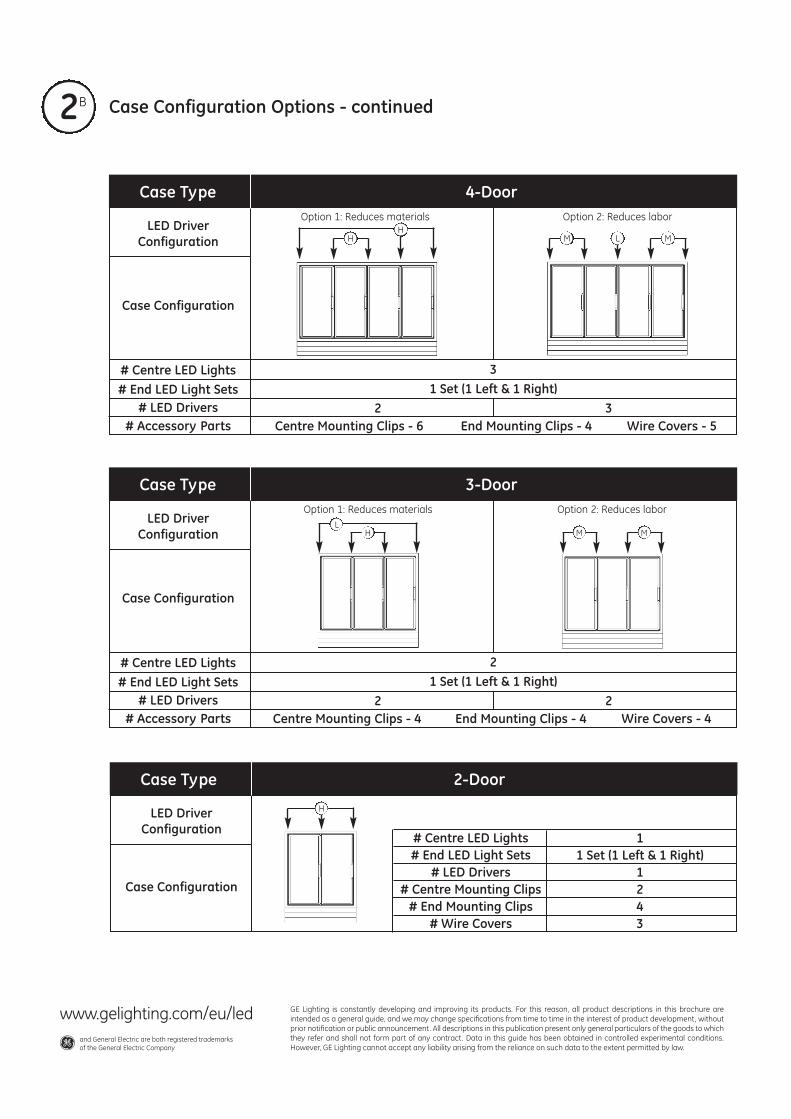
2 Case Configuration Options - continuedB
Case Type 4-Door
LED DriverConfiguration
Case Configuration
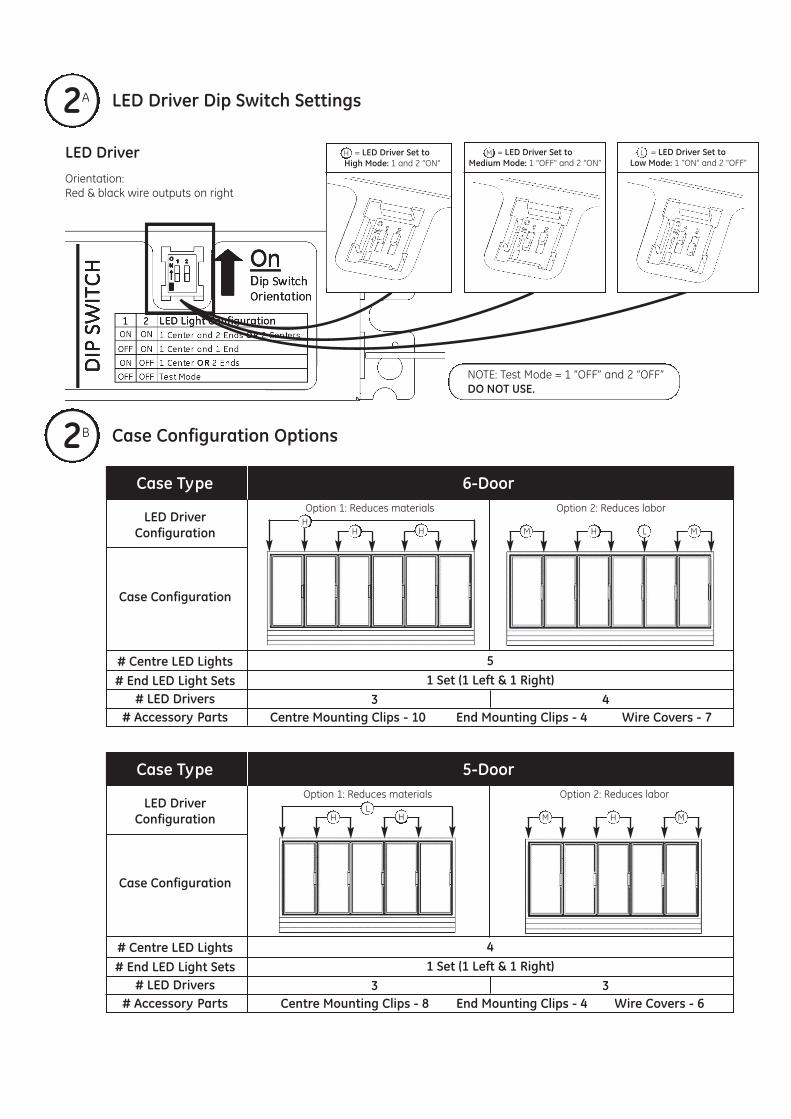
# Centre LED Lights# End LED Light Sets
# LED Drivers# Accessory Parts Centre Mounting Clips - 6 End Mounting Clips - 4 Wire Covers - 5
A. Use this unit only in the manner intended by the manufacturer.If you have any questions, contact the manufacturer.
B. Before servicing or cleaning unit, switch power off at the servicepanel and follow appropriate lock out / tag out safety procedures.
FOR YOUR SAFETYRead and observe all CAUTIONS and WARNINGS shownthroughout these instructions. • Installation to be performed by factory trained service
personnel only.• For use inside a commercial refrigeration case with packaged
foods only.
NOTE: This device complies with Part 15 of the FCC Rules. Operation is subject tothe following two conditions: (1) this device may not cause harmful interference,and (2) this device must accept any interference received, including interferencethat may cause undesired operation.
This Class [A] RFLD complies with the Canadian standard ICES-005. Ce DEFR de laclasse [A] est conforme à la NMB-005 du Canada
BEFORE YOU BEGINRead these instructions completely and carefully.
Risk of electrical shock. Disconnect power before servicing or installing product. / Risque de choc électrique. Couper l’alimentation avant le dépannage ou avant l’installation du produit.
WARNING / AVERTISSMENTRisk of injury. While performing installations described,gloves, safety glasses or goggles should be worn. / Risquede blessure. Lors de l'exécution des installations décrites,des gants, des lunettes de sécurité ou des lunettes de protection doivent être portées.
CAUTION / ATTENTION
PREPARE ELECTRICAL WIRINGElectrical Requirements• The power supply must be supplied with 100-240 VAC,
50/60 Hz., and connected to an individual properlygrounded branch circuit, protected by a 15 or 20 amperecircuit breaker or time delay fuse.
• Wiring must be 2 wire with ground and rated for 75°C
Grounding Instructions–Cable Direct• This lighting system must be connected to a grounded
metal, permanent wiring system, or an equipment grounding conductor must be run with the circuit conductors and be connected to the equipment grounding terminal or lead on the LED Light.
Conforms to the following standards:
GE imagination at work
1
Two Centre LED Lights One Centre LED Light
One End Set (Right and Left) & One Centre LED Light
One End LED Light (Right or Left) & One Centre LED Light
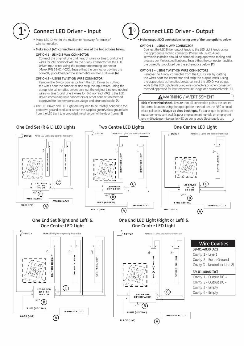
• Place LED Driver in the mullion or raceway for ease ofwire connection.
• Make input (AC) connections using one of the two options below:
OPTION 1 - USING 3-WAY CONNECTORConnect the original Line and neutral wires (or Line 1 and Line 2 wires for 240 nominal VAC) to the 3-way connector for the LED Driver input wires using the appropriate mating connector (Molex P/N 39-01-4030). Ensure that the connector cavities are correctly populated per the schematics on the LED Driver. (A)
OPTION 2 – USING TWIST-ON WIRE CONNECTORRemove the 3-way connector from the LED Driver by cutting the wires near the connector and strip the input wires. Using the apropriate schematics below, connect the original Line and neutral wires (or Line 1 and Line 2 wires for 240 nominal VAC) to the LED Driver leads using wire connectors or other connection method approved for low temperature usage and stranded cable. (A)
• The LED Driver and LED Light are required to be reliably bonded to theprotective ground conductor. Attach the supplied green/yellow ground wire from the LED Light to a grounded metal portion of the door frame. (B)
• Make output (DC) connections using one of the two options below:
OPTION 1 – USING 4-WAY CONNECTORConnect the LED Driver output leads to the LED Light leads using the appropriate mating connector (Molex P/N 39-01-4046). Terminals installed should be crimped using approved tooling and process per Molex specifications. Ensure that the connector cavities are correctly populated per the schematics below. (C)
OPTION 2 – USING TWIST-ON WIRE CONNECTORSRemove the 4-way connector from the LED Driver by cutting the wires near the connector and strip the output leads. Using the appropriate schematics below, connect the LED Driver outputleads to the LED Light leads using wire connectors or other connectionmethod approved for low temperature usage and stranded cable. (C)
Note: LED Lights are polarity insensitive Note: LED Lights are polarity insensitive
Note: LED Lights are polarity insensitiveNote: LED Lights are polarity insensitive
39-01-4046 (DC)Cavity 1 - Output DC +Cavity 2 - Output DC -Cavity 3 - EmptyCavity 4 - Empty
= LED Driver Set to High Mode: 1 and 2 “ON”H = LED Driver Set to
Medium Mode: 1 “OFF” and 2 “ON”M = LED Driver Set to
Low Mode: 1 “ON” and 2 “OFF”L
Risk of electrical shock. Ensure that all connection points are sealedfor damp location using the appropriate method per the NEC or localelectrical code. / Risque de choc électrique. S’assurer que les points deraccordements sont scellés pour emplacement humide en employantune méthode permise par le NEC ou par le code électrique local.
WARNING / AVERTISSMENT
NOTE: Test Mode = 1 “OFF” and 2 “OFF”DO NOT USE.
1Connect LED Driver - Input Connect LED Driver - Output ABA
2 Case Configuration OptionsB
1
Two Centre LED Lights One Centre LED Light
One End Set (Right and Left) & One Centre LED Light
One End LED Light (Right or Left) & One Centre LED Light
• Place LED Driver in the mullion or raceway for ease ofwire connection.
• Make input (AC) connections using one of the two options below:
OPTION 1 - USING 3-WAY CONNECTORConnect the original Line and neutral wires (or Line 1 and Line 2 wires for 240 nominal VAC) to the 3-way connector for the LED Driver input wires using the appropriate mating connector (Molex P/N 39-01-4030). Ensure that the connector cavities are correctly populated per the schematics on the LED Driver. (A)
OPTION 2 – USING TWIST-ON WIRE CONNECTORRemove the 3-way connector from the LED Driver by cutting the wires near the connector and strip the input wires. Using the apropriate schematics below, connect the original Line and neutral wires (or Line 1 and Line 2 wires for 240 nominal VAC) to the LED Driver leads using wire connectors or other connection method approved for low temperature usage and stranded cable. (A)
• The LED Driver and LED Light are required to be reliably bonded to theprotective ground conductor. Attach the supplied green/yellow ground wire from the LED Light to a grounded metal portion of the door frame. (B)
• Make output (DC) connections using one of the two options below:
OPTION 1 – USING 4-WAY CONNECTORConnect the LED Driver output leads to the LED Light leads using the appropriate mating connector (Molex P/N 39-01-4046). Terminals installed should be crimped using approved tooling and process per Molex specifications. Ensure that the connector cavities are correctly populated per the schematics below. (C)
OPTION 2 – USING TWIST-ON WIRE CONNECTORSRemove the 4-way connector from the LED Driver by cutting the wires near the connector and strip the output leads. Using the appropriate schematics below, connect the LED Driver outputleads to the LED Light leads using wire connectors or other connectionmethod approved for low temperature usage and stranded cable. (C)
Note: LED Lights are polarity insensitive Note: LED Lights are polarity insensitive
Note: LED Lights are polarity insensitiveNote: LED Lights are polarity insensitive
39-01-4046 (DC)Cavity 1 - Output DC +Cavity 2 - Output DC -Cavity 3 - EmptyCavity 4 - Empty
= LED Driver Set to High Mode: 1 and 2 “ON”H = LED Driver Set to
Medium Mode: 1 “OFF” and 2 “ON”M = LED Driver Set to
Low Mode: 1 “ON” and 2 “OFF”L
Risk of electrical shock. Ensure that all connection points are sealedfor damp location using the appropriate method per the NEC or localelectrical code. / Risque de choc électrique. S’assurer que les points deraccordements sont scellés pour emplacement humide en employantune méthode permise par le NEC ou par le code électrique local.
WARNING / AVERTISSMENT
NOTE: Test Mode = 1 “OFF” and 2 “OFF”DO NOT USE.
1Connect LED Driver - Input Connect LED Driver - Output ABA
2 Case Configuration OptionsB
2 Case Configuration Options - continuedB
Case Type 4-Door
LED DriverConfiguration
Case Configuration
# Centre LED Lights# End LED Light Sets
# LED Drivers# Accessory Parts Centre Mounting Clips - 6 End Mounting Clips - 4 Wire Covers - 5
A. Use this unit only in the manner intended by the manufacturer.If you have any questions, contact the manufacturer.
B. Before servicing or cleaning unit, switch power off at the servicepanel and follow appropriate lock out / tag out safety procedures.
FOR YOUR SAFETYRead and observe all CAUTIONS and WARNINGS shownthroughout these instructions. • Installation to be performed by factory trained service
personnel only.• For use inside a commercial refrigeration case with packaged
foods only.
NOTE: This device complies with Part 15 of the FCC Rules. Operation is subject tothe following two conditions: (1) this device may not cause harmful interference,and (2) this device must accept any interference received, including interferencethat may cause undesired operation.
This Class [A] RFLD complies with the Canadian standard ICES-005. Ce DEFR de laclasse [A] est conforme à la NMB-005 du Canada
BEFORE YOU BEGINRead these instructions completely and carefully.
Risk of electrical shock. Disconnect power before servicing or installing product. / Risque de choc électrique. Couper l’alimentation avant le dépannage ou avant l’installation du produit.
WARNING / AVERTISSMENTRisk of injury. While performing installations described,gloves, safety glasses or goggles should be worn. / Risquede blessure. Lors de l'exécution des installations décrites,des gants, des lunettes de sécurité ou des lunettes de protection doivent être portées.
CAUTION / ATTENTION
PREPARE ELECTRICAL WIRINGElectrical Requirements• The power supply must be supplied with 100-240 VAC,
50/60 Hz., and connected to an individual properlygrounded branch circuit, protected by a 15 or 20 amperecircuit breaker or time delay fuse.
• Wiring must be 2 wire with ground and rated for 75°C
Grounding Instructions–Cable Direct• This lighting system must be connected to a grounded
metal, permanent wiring system, or an equipment grounding conductor must be run with the circuit conductors and be connected to the equipment grounding terminal or lead on the LED Light.
Conforms to the following standards:
GE Lighting is constantly developing and improving its products. For this reason, all product descriptions in this brochure are intended as a general guide, and we may change specifications from time to time in the interest of product development, without prior notification or public announcement. All descriptions in this publication present only general particulars of the goods to which they refer and shall not form part of any contract. Data in this guide has been obtained in controlled experimental conditions. However, GE Lighting cannot accept any liability arising from the reliance on such data to the extent permitted by law.
www.gelighting.com/eu/ledand General Electric are both registered trademarksof the General Electric Company


![Lucalox™ Standard DATA SHEET - emea.gelighting.comemea.gelighting.com/LightingWeb/emea/images/HPS_Lucalox_Lamps_Data...Rated Lumen [lm] 6,420 9,880 15,490 17,600 28,750 33,270 48,300](https://static.documents.pub/doc/80x56/5aa336707f8b9a46238e12e4/lucalox-standard-data-sheet-emea-lumen-lm-6420-9880-15490-17600-28750.jpg)


