Overview The EBDHS-MB-AT-DD is a passive infrared (PIR) motion sensor combined with two output channels capable of controlling incandescent, fluorescent and compact fluorescent lighting. The EBDHS-MB-AT-DD is a high sensitivity PIR detector suitable for high bay applications, such as warehouses and factories, and where high detection sensitivity is needed. It is specifically designed for mounting onto a batten style luminaire. Output Channel 1 comprises a mains voltage relay capable of simple on/off switching, while Output Channel 2 provides dimmable control of either DSI or DALI type ballasts. Functioning as a presence detector, the unit can turn lights on when a room is occupied and off when the room is empty. Optional settings allow lights to be turned off in response to ambient daylight, or to implement a maintained illuminance (constant light) system. The unit also includes stored scenes for versatile manual control of lighting levels. The EBDHS-MB-AT-DD can be used as a standalone unit or integrated with other devices as part of a system. The built-in RF transceiver allows wireless communication with all other An-10 ® compatible products, e.g. the AT-BB-IN Input Unit, useful for push-button scene selection and absence detection. All functionality is fully programmable. Features PIR Sensor Detects movement within the unit’s detection range, allowing load control in response to changes in occupancy. IR Receiver Receives control and programming commands from an IR (infrared) handset. Light Level Sensor Monitors the ambient light level, allowing load control based on minimum and maximum Lux Level and also for providing Maintained Illuminance (constant light) control. Status LEDs These flash Red and/or Green to indicate the following: Power Input & Switched Output Connector (Channel 1) Used to connect mains power to the unit and to connect a switched load. Dimmable Control Output Connector (Channel 2) Used to connect DSI/DALI controllable ballasts and transformers for dimmable loads. Walk Test LED active when movement is detected Valid setting received Invalid setting received Software reset received Factory reset received RF ceiling PIR presence detector – DALI / DSI dimming EBDHS-MB-AT-DD Product Guide Front view PIR lens which covers... IR Receiver Light Level Sensor Status LED Cables to luminaire control gear
Transcript
Overview
The EBDHS-MB-AT-DD is a passive infrared (PIR) motion sensor combined with two output channels capable of controlling incandescent, fluorescent and compact fluorescent lighting. The EBDHS-MB-AT-DD is a high sensitivity PIR detector suitable for high bay applications, such as warehouses and factories, and where high detection sensitivity is needed. It is specifically designed for mounting onto a batten style luminaire. Output Channel 1 comprises a mains voltage relay capable of simple on/off switching, while Output Channel 2 provides dimmable control of either DSI or DALI type ballasts. Functioning as a presence detector, the unit can turn lights on when a room is occupied and off when the room is empty. Optional settings allow lights to be turned off in response to ambient daylight, or to implement a maintained illuminance (constant light) system. The unit also includes stored scenes for versatile manual control of lighting levels. The EBDHS-MB-AT-DD can be used as a standalone unit or integrated with other devices as part of a system. The built-in RF transceiver allows wireless communication with all other An-10® compatible products, e.g. the AT-BB-IN Input Unit, useful for push-button scene selection and absence detection. All functionality is fully programmable.
Features
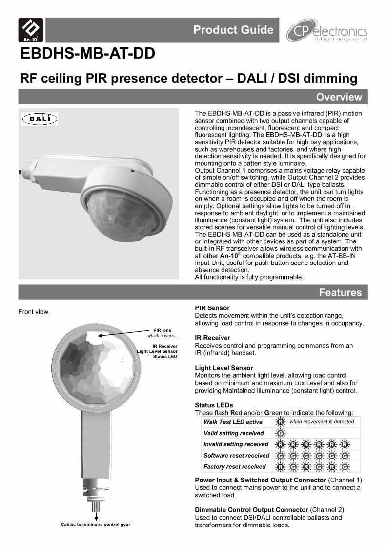
PIR Sensor Detects movement within the unit’s detection range, allowing load control in response to changes in occupancy. IR Receiver Receives control and programming commands from an IR (infrared) handset. Light Level Sensor Monitors the ambient light level, allowing load control based on minimum and maximum Lux Level and also for providing Maintained Illuminance (constant light) control. Status LEDs These flash Red and/or Green to indicate the following:
Power Input & Switched Output Connector (Channel 1) Used to connect mains power to the unit and to connect a switched load. Dimmable Control Output Connector (Channel 2) Used to connect DSI/DALI controllable ballasts and transformers for dimmable loads.
Walk Test LED active when movement is detected
Valid setting received
Invalid setting received
Software reset received
Factory reset received
RF ceiling PIR presence detector – DALI / DSI dimming
EBDHS-MB-AT-DD
Product Guide
Front view
PIR lens which covers...
IR Receiver
Light Level Sensor Status LED
Cables to luminaire control gear
2
Detection diagrams
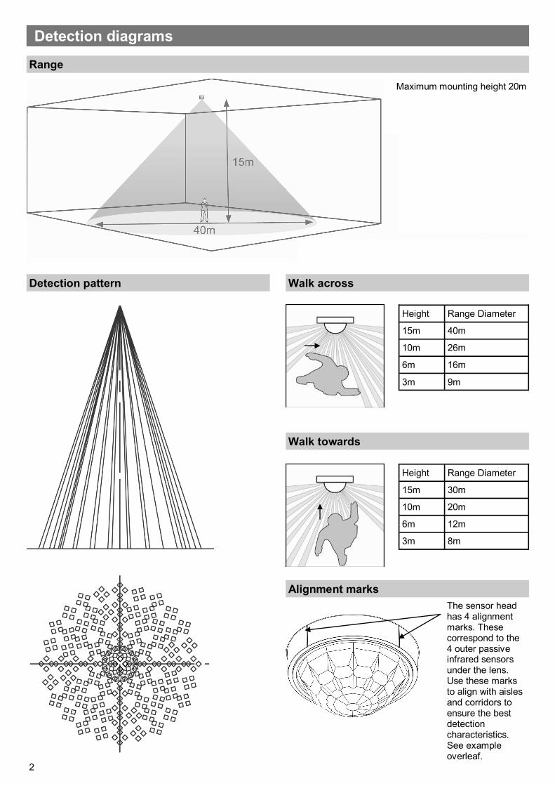
Range
Detection pattern Walk across
Maximum mounting height 20m
Walk towards
Height Range Diameter
15m 30m
10m 20m
6m 12m
3m 8m
Height Range Diameter
15m 40m
10m 26m
6m 16m
3m 9m
Alignment marks
The sensor head has 4 alignment marks. These correspond to the 4 outer passive infrared sensors under the lens. Use these marks to align with aisles and corridors to ensure the best detection characteristics. See example overleaf.
3
Masking
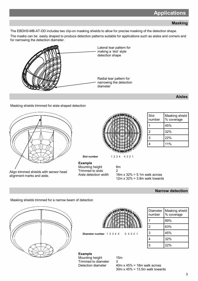
The EBDHS-MB-AT-DD includes two clip-on masking shields to allow for precise masking of the detection shape.
The masks can be easily shaped to produce detection patterns suitable for applications such as aisles and corners and for narrowing the detection diameter.
Radial tear pattern for narrowing the detection diameter
Lateral tear pattern for making a ‘slot’ style detection shape
Applications
Aisles
Masking shields trimmed for aisle shaped detection
Narrow detection
Masking shields trimmed for a narrow beam of detection
1 2 3 4 4 3 2 1
Slot number
Masking shield % coverage
1 45%
2 32%
3 22%
4 11%
Slot number
2 3 4
Diameter number
Masking shield % coverage
1 89%
2 63%
3 45%
4 32%
5 22%
5 5 4 3 2 1 Diameter number 1
Example Mounting height 6m Trimmed to slots 2 Aisle detection width 16m x 32% = 5.1m walk across 12m x 32% = 3.8m walk towards
Example Mounting height 15m Trimmed to diameter 3 Detection diameter 40m x 45% = 18m walk across 30m x 45% = 13.5m walk towards
Align trimmed shields with sensor head alignment marks and aisle.
4
Installation
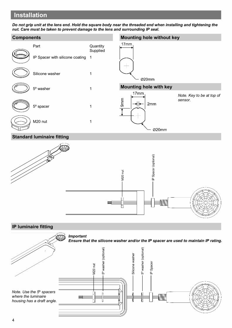
Components
Standard luminaire fitting
IP luminaire fitting
Part Quantity Supplied
IP Spacer with silicone coating 1
Silicone washer 1
5º washer 1
5º spacer 1
M20 nut 1
Mounting hole without key
Mounting hole with key
Note. Key to be at top of sensor.
Note. Use the 5º spacers where the luminaire housing has a draft angle.
Important Ensure that the silicone washer and/or the IP spacer are used to maintain IP rating.
Do not grip unit at the lens end. Hold the square body near the threaded end when installing and tightening the nut. Care must be taken to prevent damage to the lens and surrounding IP seal.
5
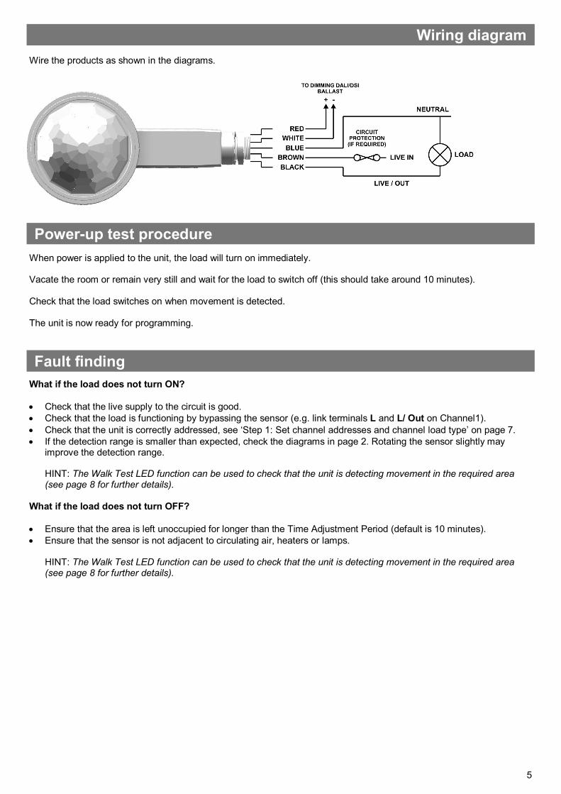
Wiring diagram
Wire the products as shown in the diagrams.
When power is applied to the unit, the load will turn on immediately. Vacate the room or remain very still and wait for the load to switch off (this should take around 10 minutes). Check that the load switches on when movement is detected. The unit is now ready for programming.
Power-up test procedure
What if the load does not turn ON?
Check that the live supply to the circuit is good.
Check that the load is functioning by bypassing the sensor (e.g. link terminals L and L/ Out on Channel1).
Check that the unit is correctly addressed, see ‘Step 1: Set channel addresses and channel load type’ on page 7.
If the detection range is smaller than expected, check the diagrams in page 2. Rotating the sensor slightly may improve the detection range. HINT: The Walk Test LED function can be used to check that the unit is detecting movement in the required area (see page 8 for further details).
What if the load does not turn OFF?
Ensure that the area is left unoccupied for longer than the Time Adjustment Period (default is 10 minutes).
Ensure that the sensor is not adjacent to circulating air, heaters or lamps. HINT: The Walk Test LED function can be used to check that the unit is detecting movement in the required area (see page 8 for further details).
Fault finding
6
Basic programming
The functionality of the EBDHS-MB-AT-DD Sensor is controlled by a number of parameters which can be changed or programmed by any of the following devices:
UHS4 Infrared Handset
UNLCDHS Infrared Handset (with LCD)
For most basic programming operations the UHS4 handset is recommended and the following procedures are based on using this device. Point the handset at the Sensor and send the required programming commands to the unit as shown in Steps 1, 2 and 3. Valid commands will be indicated by a green LED flash. See page 1 for details of other LED responses.
7
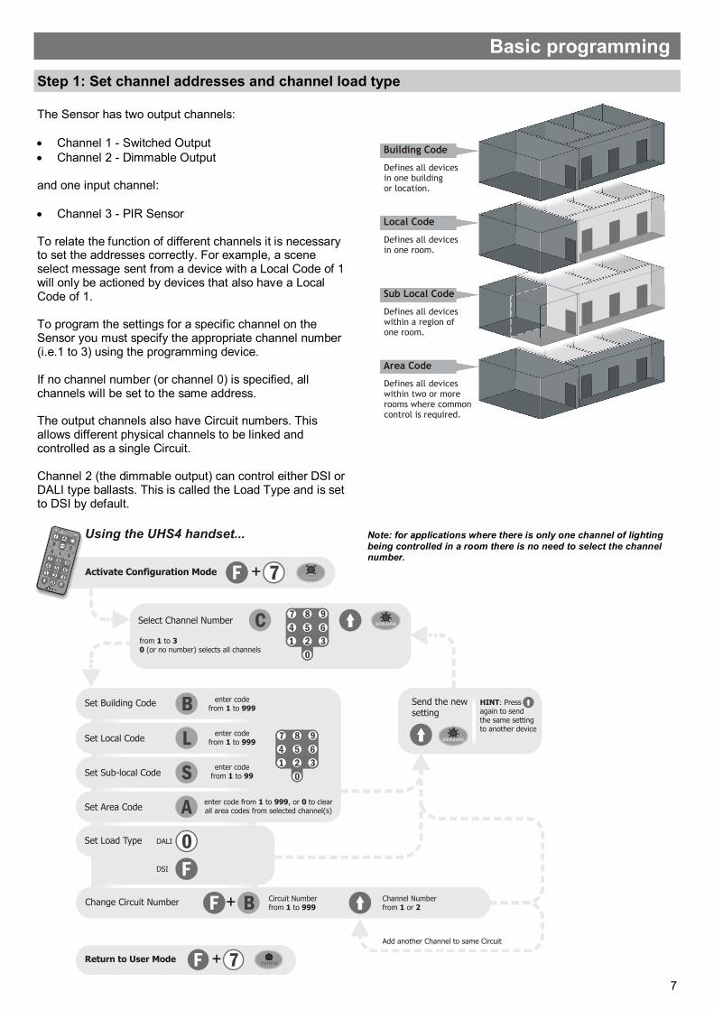
Step 1: Set channel addresses and channel load type
The Sensor has two output channels:
Channel 1 - Switched Output
Channel 2 - Dimmable Output
and one input channel:
Channel 3 - PIR Sensor To relate the function of different channels it is necessary to set the addresses correctly. For example, a scene select message sent from a device with a Local Code of 1 will only be actioned by devices that also have a Local Code of 1. To program the settings for a specific channel on the Sensor you must specify the appropriate channel number (i.e.1 to 3) using the programming device. If no channel number (or channel 0) is specified, all channels will be set to the same address. The output channels also have Circuit numbers. This allows different physical channels to be linked and controlled as a single Circuit. Channel 2 (the dimmable output) can control either DSI or DALI type ballasts. This is called the Load Type and is set to DSI by default.
Note: for applications where there is only one channel of lighting
being controlled in a room there is no need to select the channel number.
Basic programming
8
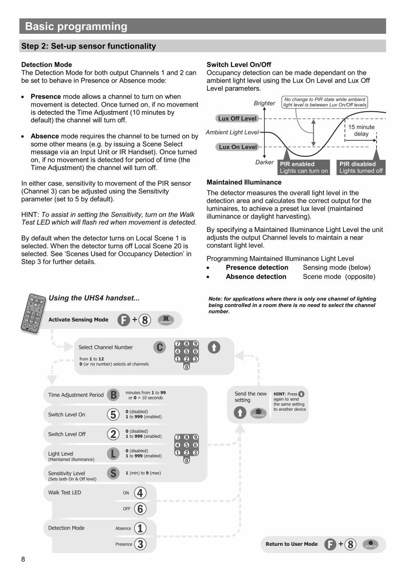
Detection Mode The Detection Mode for both output Channels 1 and 2 can be set to behave in Presence or Absence mode:
Presence mode allows a channel to turn on when movement is detected. Once turned on, if no movement is detected the Time Adjustment (10 minutes by default) the channel will turn off.
Absence mode requires the channel to be turned on by some other means (e.g. by issuing a Scene Select message via an Input Unit or IR Handset). Once turned on, if no movement is detected for period of time (the Time Adjustment) the channel will turn off.
In either case, sensitivity to movement of the PIR sensor (Channel 3) can be adjusted using the Sensitivity parameter (set to 5 by default). HINT: To assist in setting the Sensitivity, turn on the Walk Test LED which will flash red when movement is detected. By default when the detector turns on Local Scene 1 is selected. When the detector turns off Local Scene 20 is selected. See ‘Scenes Used for Occupancy Detection’ in Step 3 for further details.
Step 2: Set-up sensor functionality
Switch Level On/Off Occupancy detection can be made dependant on the ambient light level using the Lux On Level and Lux Off Level parameters.
Maintained Illuminance
The detector measures the overall light level in the detection area and calculates the correct output for the luminaires, to achieve a preset lux level (maintained illuminance or daylight harvesting).
By specifying a Maintained Illuminance Light Level the unit adjusts the output Channel levels to maintain a near constant light level.
Programming Maintained Illuminance Light Level
Presence detection Sensing mode (below)
Absence detection Scene mode (opposite)
Basic programming
Note: for applications where there is only one channel of lighting
being controlled in a room there is no need to select the channel number.
9
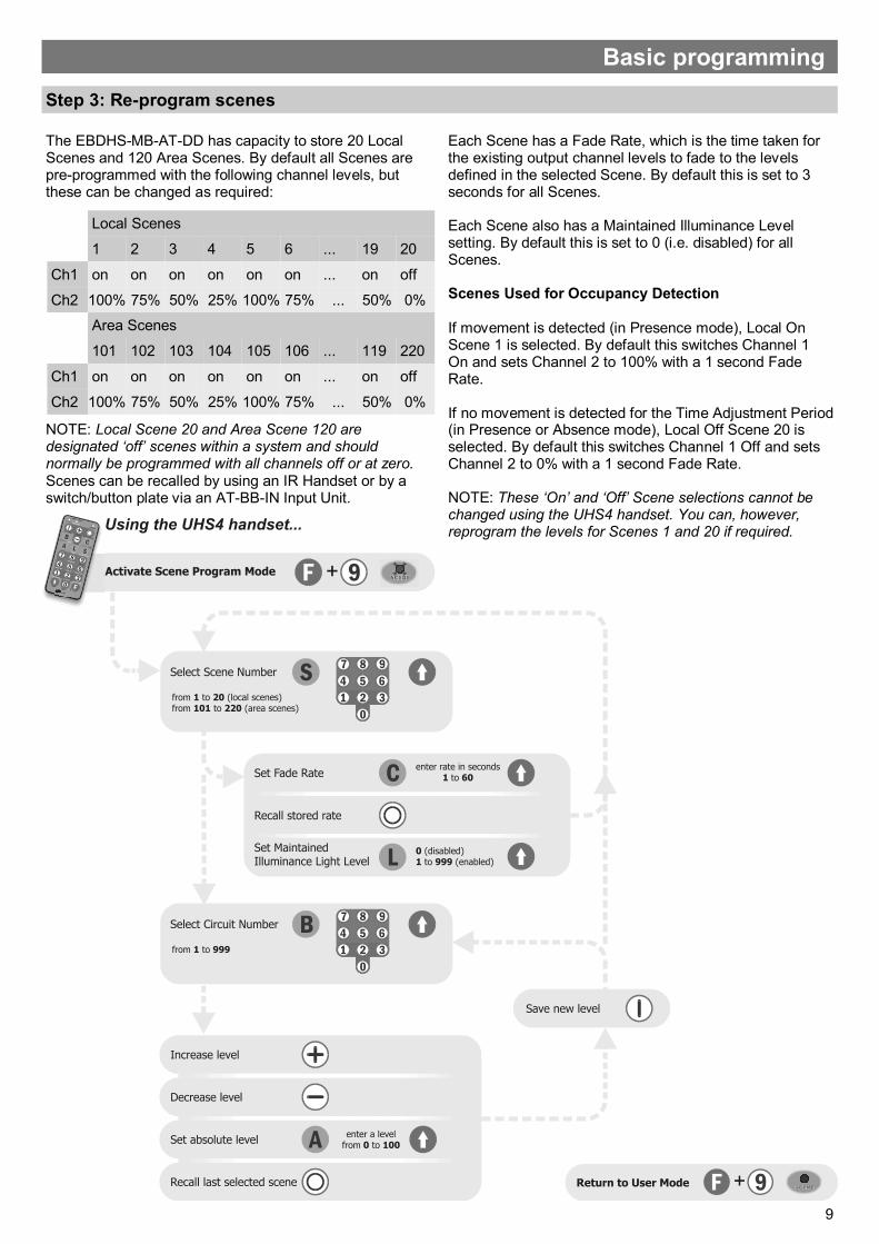
The EBDHS-MB-AT-DD has capacity to store 20 Local Scenes and 120 Area Scenes. By default all Scenes are pre-programmed with the following channel levels, but these can be changed as required:
NOTE: Local Scene 20 and Area Scene 120 are designated ‘off’ scenes within a system and should normally be programmed with all channels off or at zero. Scenes can be recalled by using an IR Handset or by a switch/button plate via an AT-BB-IN Input Unit.
Local Scenes
1 2 3 4 5 6 ... 19 20
Ch1 on on on on on on ... on off
Ch2 100% 75% 50% 25% 100% 75% ... 50% 0%
Area Scenes
101 102 103 104 105 106 ... 119 220
Ch1 on on on on on on ... on off
Ch2 100% 75% 50% 25% 100% 75% ... 50% 0%
Step 3: Re-program scenes
Each Scene has a Fade Rate, which is the time taken for the existing output channel levels to fade to the levels defined in the selected Scene. By default this is set to 3 seconds for all Scenes. Each Scene also has a Maintained Illuminance Level setting. By default this is set to 0 (i.e. disabled) for all Scenes. Scenes Used for Occupancy Detection If movement is detected (in Presence mode), Local On Scene 1 is selected. By default this switches Channel 1 On and sets Channel 2 to 100% with a 1 second Fade Rate. If no movement is detected for the Time Adjustment Period (in Presence or Absence mode), Local Off Scene 20 is selected. By default this switches Channel 1 Off and sets Channel 2 to 0% with a 1 second Fade Rate. NOTE: These ‘On’ and ‘Off’ Scene selections cannot be changed using the UHS4 handset. You can, however, reprogram the levels for Scenes 1 and 20 if required.
Basic programming
10
Advanced programming
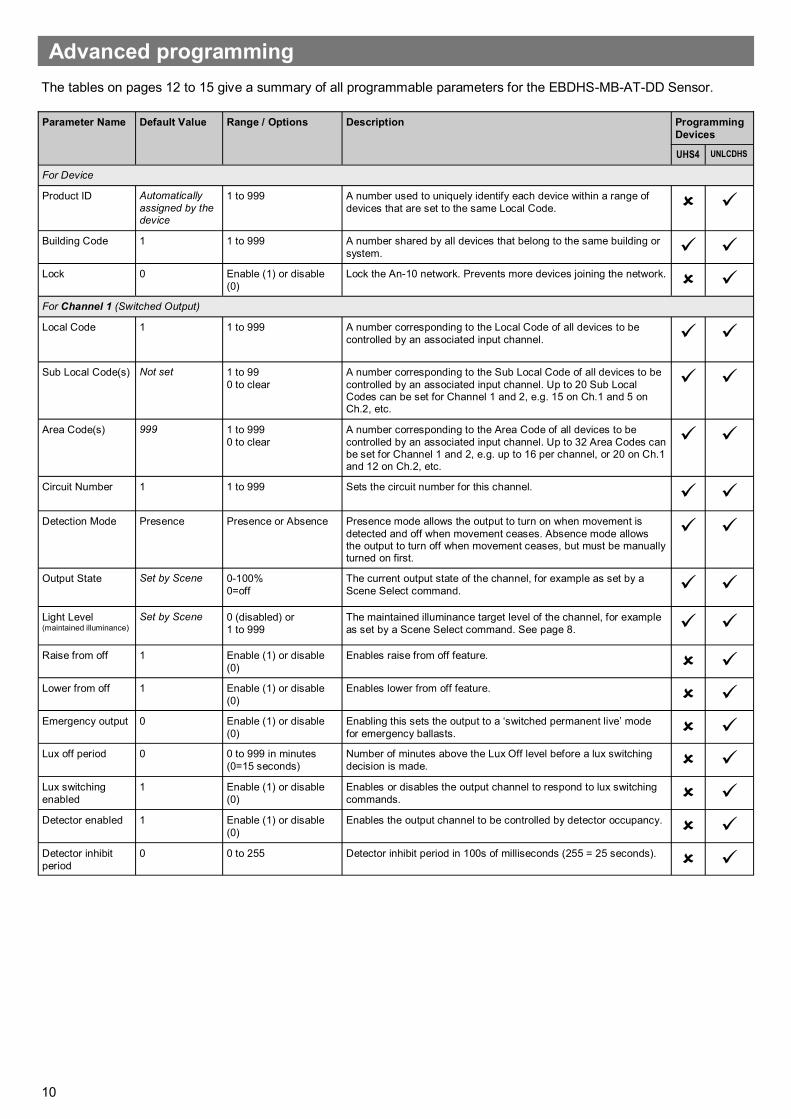
The tables on pages 12 to 15 give a summary of all programmable parameters for the EBDHS-MB-AT-DD Sensor.
Parameter Name Default Value Range / Options Description Programming
Devices
UHS4 UNLCDHS
For Device
Product ID Automatically
assigned by the device
1 to 999 A number used to uniquely identify each device within a range of
devices that are set to the same Local Code.
Building Code 1 1 to 999 A number shared by all devices that belong to the same building or
system.
Lock 0 Enable (1) or disable
(0)
Lock the An-10 network. Prevents more devices joining the network.
For Channel 1 (Switched Output)
Local Code 1 1 to 999 A number corresponding to the Local Code of all devices to be
controlled by an associated input channel.
Sub Local Code(s) Not set 1 to 99
0 to clear
A number corresponding to the Sub Local Code of all devices to be
controlled by an associated input channel. Up to 20 Sub Local Codes can be set for Channel 1 and 2, e.g. 15 on Ch.1 and 5 on Ch.2, etc.
Area Code(s) 999 1 to 999
0 to clear
A number corresponding to the Area Code of all devices to be
controlled by an associated input channel. Up to 32 Area Codes can be set for Channel 1 and 2, e.g. up to 16 per channel, or 20 on Ch.1 and 12 on Ch.2, etc.
Circuit Number 1 1 to 999 Sets the circuit number for this channel.
Detection Mode Presence Presence or Absence Presence mode allows the output to turn on when movement is
detected and off when movement ceases. Absence mode allows the output to turn off when movement ceases, but must be manually turned on first.
Output State Set by Scene
0-100%
0=off
The current output state of the channel, for example as set by a
Scene Select command.
Light Level (maintained illuminance)
Set by Scene 0 (disabled) or
1 to 999
The maintained illuminance target level of the channel, for example
as set by a Scene Select command. See page 8.
Raise from off 1 Enable (1) or disable
(0)
Enables raise from off feature.
Lower from off 1 Enable (1) or disable
(0)
Enables lower from off feature.
Emergency output 0 Enable (1) or disable
(0)
Enabling this sets the output to a ‘switched permanent live’ mode
for emergency ballasts.
Lux off period 0 0 to 999 in minutes
(0=15 seconds)
Number of minutes above the Lux Off level before a lux switching
decision is made.
Lux switching
enabled
1 Enable (1) or disable
(0)
Enables or disables the output channel to respond to lux switching
commands.
Detector enabled 1 Enable (1) or disable
(0)
Enables the output channel to be controlled by detector occupancy.
Detector inhibit
period
0 0 to 255 Detector inhibit period in 100s of milliseconds (255 = 25 seconds).
11
Parameter Name Default Value Range / Options Description Programming
Devices
UHS4 UNLCDHS
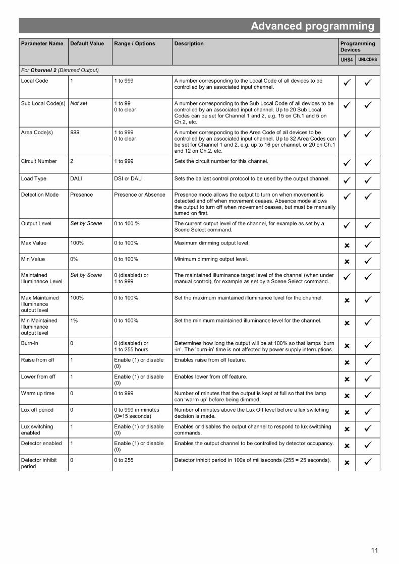
For Channel 2 (Dimmed Output)
Local Code 1 1 to 999 A number corresponding to the Local Code of all devices to be
controlled by an associated input channel.
Sub Local Code(s) Not set 1 to 99
0 to clear
A number corresponding to the Sub Local Code of all devices to be
controlled by an associated input channel. Up to 20 Sub Local Codes can be set for Channel 1 and 2, e.g. 15 on Ch.1 and 5 on Ch.2, etc.
Area Code(s) 999 1 to 999
0 to clear
A number corresponding to the Area Code of all devices to be
controlled by an associated input channel. Up to 32 Area Codes can be set for Channel 1 and 2, e.g. up to 16 per channel, or 20 on Ch.1 and 12 on Ch.2, etc.
Circuit Number 2 1 to 999 Sets the circuit number for this channel.
Load Type DALI DSI or DALI Sets the ballast control protocol to be used by the output channel.
Detection Mode Presence Presence or Absence Presence mode allows the output to turn on when movement is
detected and off when movement ceases. Absence mode allows the output to turn off when movement ceases, but must be manually turned on first.
Output Level Set by Scene
0 to 100 % The current output level of the channel, for example as set by a
Scene Select command.
Max Value 100% 0 to 100% Maximum dimming output level.
Min Value 0% 0 to 100% Minimum dimming output level.
Maintained
Illuminance Level
Set by Scene 0 (disabled) or
1 to 999
The maintained illuminance target level of the channel (when under
manual control), for example as set by a Scene Select command.
Max Maintained
Illuminance output level
100% 0 to 100% Set the maximum maintained illuminance level for the channel.
Min Maintained
Illuminance output level
1% 0 to 100% Set the minimum maintained illuminance level for the channel.
Burn-in 0 0 (disabled) or
1 to 255 hours
Determines how long the output will be at 100% so that lamps ‘burn
-in’. The ’burn-in’ time is not affected by power supply interruptions.
Raise from off 1 Enable (1) or disable
(0)
Enables raise from off feature.
Lower from off 1 Enable (1) or disable
(0)
Enables lower from off feature.
Warm up time 0 0 to 999 Number of minutes that the output is kept at full so that the lamp
can ‘warm up’ before being dimmed.
Lux off period 0 0 to 999 in minutes
(0=15 seconds)
Number of minutes above the Lux Off level before a lux switching
decision is made.
Lux switching
enabled
1 Enable (1) or disable
(0)
Enables or disables the output channel to respond to lux switching
commands.
Detector enabled 1 Enable (1) or disable
(0)
Enables the output channel to be controlled by detector occupancy.
Detector inhibit
period
0 0 to 255 Detector inhibit period in 100s of milliseconds (255 = 25 seconds).
Advanced programming
12
Parameter Name Default Value Range / Options Description Programming
Devices
UHS4 UNLCDHS
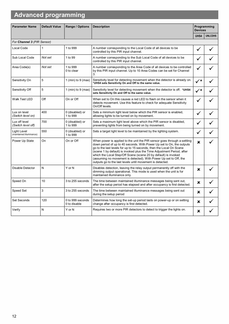
For Channel 3 (PIR Sensor)
Local Code 1 1 to 999 A number corresponding to the Local Code of all devices to be
controlled by this PIR input channel. Sub Local Code Not set 1 to 99 A number corresponding to the Sub Local Code of all devices to be
controlled by this PIR input channel.
Area Code(s) Not set 1 to 999
0 to clear
A number corresponding to the Area Code of all devices to be controlled
by this PIR input channel. Up to 10 Area Codes can be set for Channel 3.
Sensitivity On 5 1 (min) to 9 (max) Sensitivity level for detecting movement when the detector is already on. *UHS4 sets Sensitivity On and Off to the same value. *
Sensitivity Off 5 1 (min) to 9 (max) Sensitivity level for detecting movement when the detector is off. *UHS4
sets Sensitivity On and Off to the same value. * Walk Test LED Off On or Off When set to On this causes a red LED to flash on the sensor when it
detects movement. Use this feature to check for adequate Sensitivity On/Off levels.
Lux on level (Switch level on)
400 0 (disabled) or
1 to 999
Sets a minimum light level below which the PIR sensor is enabled,
allowing lights to be turned on by movement.
Lux off level (Switch level off)
700 0 (disabled) or
1 to 999
Sets a maximum light level above which the PIR sensor is disabled,
preventing lights from being turned on by movement.
Light Level (maintained illuminance)
550 0 (disabled) or
1 to 999
Sets a target light level to be maintained by the lighting system.
Power Up State On On or Off When power is applied to the unit the PIR sensor goes through a settling
down period of up to 40 seconds. With Power Up set to On, the outputs go to the last levels for up to 15 seconds, then the Local On Scene (scene 1 by default) is invoked plus the Time Adjustment Period, after
which the Local Step/Off Scene (scene 20 by default) is invoked (assuming no movement is detected). With Power Up set to Off, the outputs go to the last levels until movement is detected.
Disable Detector N Y or N Disables detection, leaving the relay output permanently off with the
dimming output operational. This mode is used when the unit is for maintained illuminance only.
Speed On 10 3 to 255 seconds The time between maintained illuminance messages being sent out,
after the setup period has elapsed and after occupancy is first detected.
Speed Set 3 3 to 255 seconds The time between maintained illuminance messages being sent out
during the setup period
Set Seconds 120 0 to 999 seconds
0 to disable
Determines how long the set-up period lasts on power-up or on setting
change after occupancy is first detected.
Verify N Y or N Requires two or more PIR detectors to detect to trigger the lights on.
Advanced programming
13
Parameter Name Default Value Range / Options Description Programming
Devices
UHS4 UNLCDHS
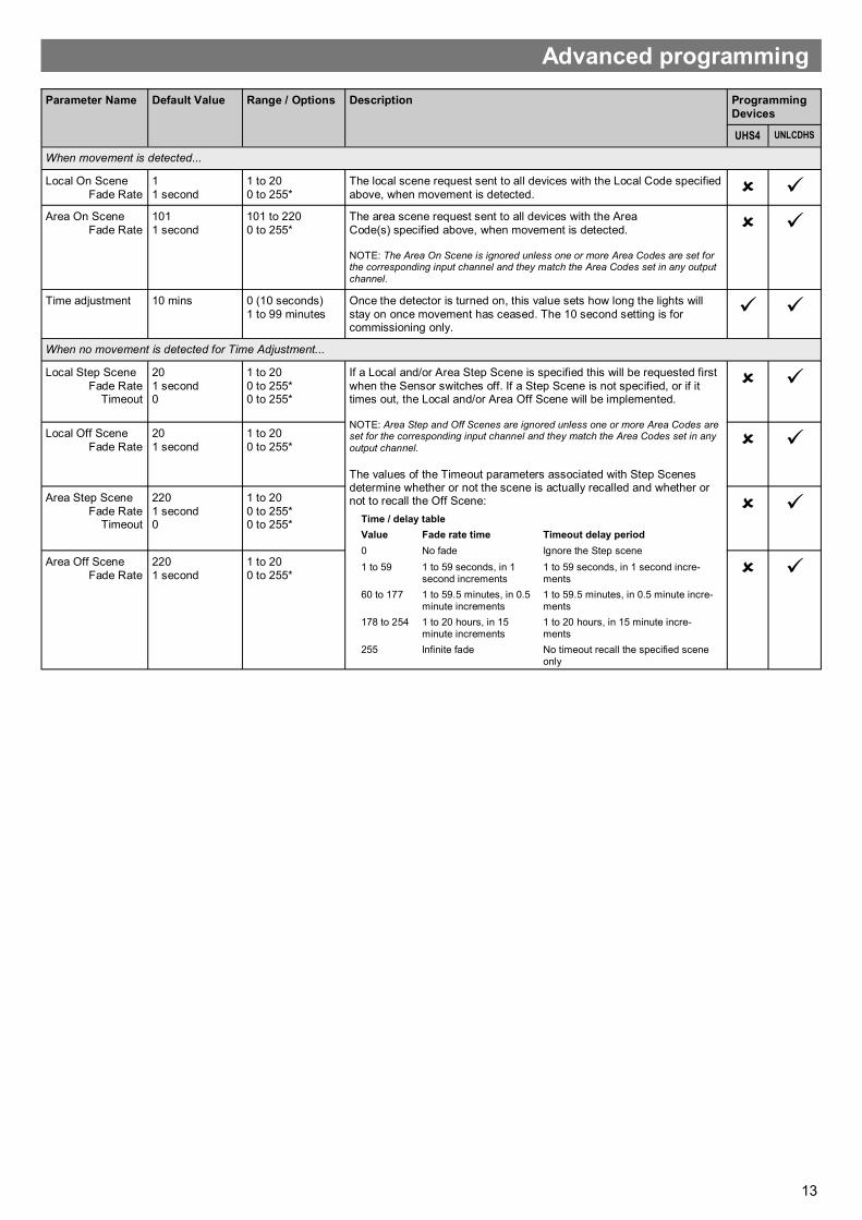
When movement is detected...
Local On Scene
Fade Rate
1
1 second
1 to 20
0 to 255*
The local scene request sent to all devices with the Local Code specified
above, when movement is detected.
Area On Scene
Fade Rate
101
1 second
101 to 220
0 to 255*
The area scene request sent to all devices with the Area
Code(s) specified above, when movement is detected. NOTE: The Area On Scene is ignored unless one or more Area Codes are set for the corresponding input channel and they match the Area Codes set in any output
channel.
Time adjustment 10 mins 0 (10 seconds)
1 to 99 minutes
Once the detector is turned on, this value sets how long the lights will
stay on once movement has ceased. The 10 second setting is for commissioning only.
When no movement is detected for Time Adjustment...
Local Step Scene
Fade Rate Timeout
20
1 second 0
1 to 20
0 to 255* 0 to 255*
If a Local and/or Area Step Scene is specified this will be requested first
when the Sensor switches off. If a Step Scene is not specified, or if it times out, the Local and/or Area Off Scene will be implemented. NOTE: Area Step and Off Scenes are ignored unless one or more Area Codes are set for the corresponding input channel and they match the Area Codes set in any
output channel.
The values of the Timeout parameters associated with Step Scenes determine whether or not the scene is actually recalled and whether or not to recall the Off Scene:
Local Off Scene
Fade Rate
20
1 second
1 to 20
0 to 255*
Area Step Scene
Fade Rate Timeout
220
1 second 0
1 to 20
0 to 255* 0 to 255*
Area Off Scene
Fade Rate
220
1 second
1 to 20
0 to 255*
Advanced programming
Time / delay table
Value Fade rate time Timeout delay period
0 No fade Ignore the Step scene
1 to 59 1 to 59 seconds, in 1 second increments
1 to 59 seconds, in 1 second incre-ments
60 to 177 1 to 59.5 minutes, in 0.5 minute increments
1 to 59.5 minutes, in 0.5 minute incre-ments
178 to 254 1 to 20 hours, in 15 minute increments
1 to 20 hours, in 15 minute incre-ments
255 Infinite fade No timeout recall the specified scene only
14
This page intentionally left blank
15
This page intentionally left blank
16
Due to our policy of continual product improvement CP Electronics reserves the right to alter the specification of this product without prior notice.
C.P. Electronics Ltd
Brent Crescent London NW10 7XR
United Kingdom
Ref: #WD767 Issue 1
Technical data
EBDHS-MB-AT-PRM RF Luminaire mount high bay PIR presence detector – switched EBDHS-MB-AT-AD RF Luminaire mount high bay PIR presence detector – 1-10V dimming EBDHS-MB-AT-DD RF Luminaire mount high bay PIR presence detector – DALI/DSI dimming AT-BB-IN RF Input unit AT-SL-R RF relay controller AT-SL-R-SA RF relay controller (standalone) AT-SL-DDR RF DALI/DSI + relay controller AT-SL-DDR-SA RF DALI/DSI + relay controller (standalone) AT-SL-ADR RF 1-10V + relay controller AT-SL-ADR-SA RF 1-10V + relay controller (standalone) VITM4-ATMOD RF Switching module VITM6-ATMOD-AD RF VITM6 1-10V module VITM6-ATMOD-DD RF VITM6 DALI/DSI module UHS4 Programming IR handset UNLCDHS Universal LCD IR handset
Part numbers
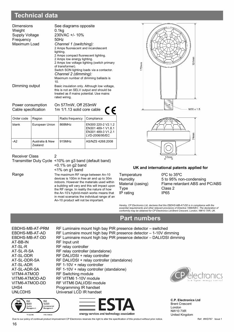
Hereby, CP Electronics Ltd, declares that this EBDHS-MB-AT-DD is in compliance with the essential requirements and other relevant provisions of Directive 1999/5/EC. The declaration of conformity may be obtained for CP Electronics Ltd Brent Crescent, London, NW10 7XR, UK.
Dimensions See diagrams opposite Weight 0.1kg Supply Voltage 230VAC +/- 10% Frequency 50Hz Maximum Load Channel 1 (switching): 2 Amps fluorescent and incandescent
lighting.
2 Amps compact fluorescent lighting. 2 Amps low energy lighting. 2 Amps low voltage lighting (switch primary
of transformer). Switch SON lighting loads via a contactor.
Channel 2 (dimming): Maximum number of dimming ballasts is 10.
Dimming output Basic insulation only. Although low voltage,
this is not an SELV output and should be treated as if mains potential. Use mains rated wiring.
Power consumption On 577mW, Off 253mW Cable specification 1m 1/1.13 solid core cable
Receiver Class 2 Transmitter Duty Cycle <10% on g3 band (default band)
<0.1% on g2 band <1% on g1 band
Range The maximum RF range between An-10
devices is 100m in free air and up to 30m indoors. However the materials used within
a building will vary and this will impact upon the RF range. In reality the nature of how the An-10’s hybrid-mesh works means that
in most scenarios the individual range of an An-10 product will not be important.