IMPLEMENTATION OF IEEE 802.15.4 PROTOCOL STACK FOR LINUX. by Sandeep Sirpatil A thesis submitted to the faculty of The University of North Carolina at Charlotte in partial fulfillment of the requirements for the degree of Master of Science in the Department of Electrical and Computer Engineering Charlotte 2006 Approved by: ______________________________ Dr. James M. Conrad ______________________________ Dr. Ivan L. Howitt ______________________________ Dr. Bharat S. Joshi
Transcript
IMPLEMENTATION OF IEEE 802.15.4 PROTOCOL STACK FOR LINUX.
by
Sandeep Sirpatil
A thesis submitted to the faculty of The University of North Carolina at Charlotte
in partial fulfillment of the requirements for the degree of Master of Science in the
Department of Electrical and Computer Engineering
Charlotte
2006
Approved by:
______________________________ Dr. James M. Conrad
______________________________ Dr. Ivan L. Howitt
______________________________ Dr. Bharat S. Joshi
The TS-7200 features a true IDE compact Flash socket. A compact Flash card in
the socket appears as a hard drive to the operating system. Compact Flash cards are
available in a wide range of capacities. A 512 MB card is sufficient to install a
customized version of Debian Linux distribution. The board also features USB and
Ethernet ports which can be used to connect to other devices. This board serves right for
a PAN coordinator as it is expected to be the master controller.
Figure 3.3: TS-7200 Hardware Components [8]
CHAPTER4: SOFTWARE DESCRIPTION
4.1 System Setup
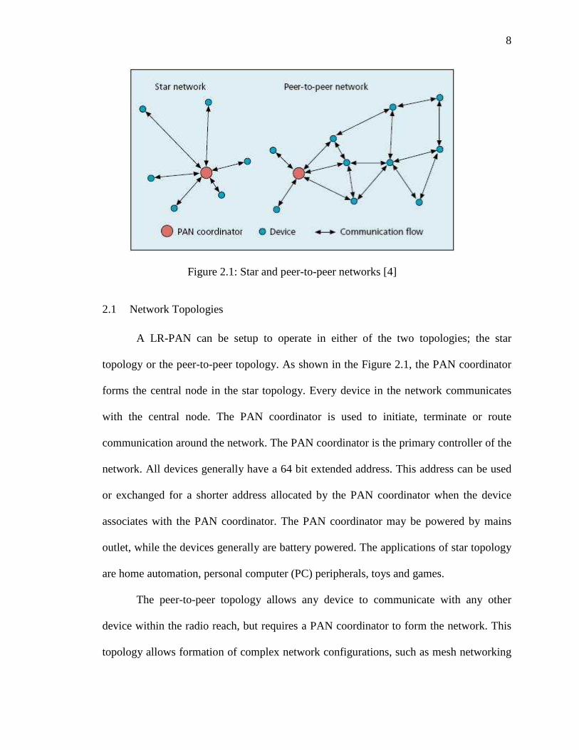
The setup consists of the CC2420DBK, TS-7200, Desktop, Laptop, Router, and
two JTAGICE mkII debuggers. Figure 4.1 illustrates the setup. The laptop, desktop and
TS-7200 were connected to the router to form a local area network (LAN). The desktop
computer is connected to one of the CC2420DB via JTAGICE mkII debugger. This setup
forms one node of the wireless network. The other CC2420DB and TS-7200 connected
via RS-232 form another node and this CC2420DB is connected to the Laptop via
another JTAGICE mkII.
The router is the dynamic host configuration protocol (DHCP) server of the
network. The DHCP server was configured to assign specific Internet Protocol (IP)
addresses to the desktop, laptop and TS-7200 which were 192.168.100, 192.168.0.101
and 192.168.0.102 respectively.
28
4.2 Atmel Development Environment
4.2.1 AVR Studio
AVR Studio is an Integrated Development Environment (IDE) for assembling and
debugging AVR application in windows environment. It provides a project management
tool, source file editor and chip simulator and interfaces with the JTAGICE mkII for
downloading and debugging of applications. The AVR Studio also has a symbolic source
level debugger, with features for Break Points, variables watch/ edit, single stepping.
Additional features can be added through the use of plugins.
Figure 4.1: Setup overview
29
4.2.2 WinAVR
WinAVR is a suite of executable, open source software development tools for the
Atmel AVR series of microcontrollers hosted in windows platform. The installation and
usage instructions can be found in the user manual [24].
The software development tools include:
• Compilers
• Assemblers
• Linker
• Librarian
• File converters
• C Library
• Debugger
• In-Circuit Emulator software
• Many support utilities.
All the software for the ATmega128L microcontroller was developed using
WinAVR tools version 20060421 and AVR Studio version 4.12b.
4.3 Linux Environment
The TS-7200 comes with TS-Linux embedded distribution installed in the on-
board Flash memory. TS-Linux is a compact distribution, based on Busybox, ideal for
small footprint. BusyBox combines tiny versions of many common Linux/UNIX utilities
into a single small executable. A full featured Linux distribution can also be run on either
the Network File System (NFS) root file system or installed on a large CompactFlash
card.
30
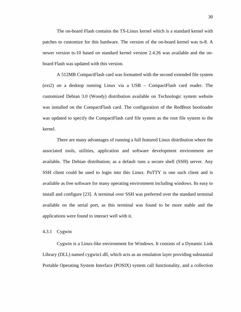
The on-board Flash contains the TS-Linux kernel which is a standard kernel with
patches to customize for this hardware. The version of the on-board kernel was ts-8. A
newer version ts-10 based on standard kernel version 2.4.26 was available and the on-
board Flash was updated with this version.
A 512MB CompactFlash card was formatted with the second extended file system
(ext2) on a desktop running Linux via a USB – CompactFlash card reader. The
customized Debian 3.0 (Woody) distribution available on Technologic system website
was installed on the CompactFlash card. The configuration of the RedBoot bootloader
was updated to specify the CompactFlash card file system as the root file system to the
kernel.
There are many advantages of running a full featured Linux distribution where the
associated tools, utilities, application and software development environment are
available. The Debian distribution; as a default runs a secure shell (SSH) server. Any
SSH client could be used to login into this Linux. PuTTY is one such client and is
available as free software for many operating environment including windows. Its easy to
install and configure [23]. A terminal over SSH was preferred over the standard terminal
available on the serial port, as this terminal was found to be more stable and the
applications were found to interact well with it.
4.3.1 Cygwin
Cygwin is a Linux-like environment for Windows. It consists of a Dynamic Link
Library (DLL) named cygwin1.dll, which acts as an emulation layer providing substantial
Portable Operating System Interface (POSIX) system call functionality, and a collection
31
of tools, which provide a Linux look and feel. Many of the Linux applications are ported
to execute in Cygwin environment [22].
An NFS server was installed in the Cygwin, the installation steps [17] by H.
Sparks were found helpful. It was setup to run and export a local folder “/usr/Sandy”. The
TS-7200 was configured to mount this folder at location “/mnt/laptop/” automatically on
boot up by adding an entry in the “/etc/fstab” file. This setup would make the folder
visible to both the systems, thus enabling file and application sharing. Additional
installation and configuration information can be found in the Linux NFS how to [16].
Technologic Systems provides Linux programming tools (toolchain) for Cygwin
environment. The toochain was installed on Cygwin, thus allowing Linux applications for
TS-7200 to be built from the Cygwin environment. The Cygwin environment was
preferred over natively building applications on TS-7200, since the laptop computer
offered more computational resources.
4.4 Stack Overview
The software stack implementation is split into two parts, one part of the stack is
implemented on the Linux side and the other part resides on the ATmega128L
microcontroller. The Linux section implements the device independent higher level
functionality of the stack. The device specific part is implemented on the ATmega128L.
This allows for easy porting to new 802.15.4 RF transceivers.
32
4.4.1 Linux - Media Access control (MAC)
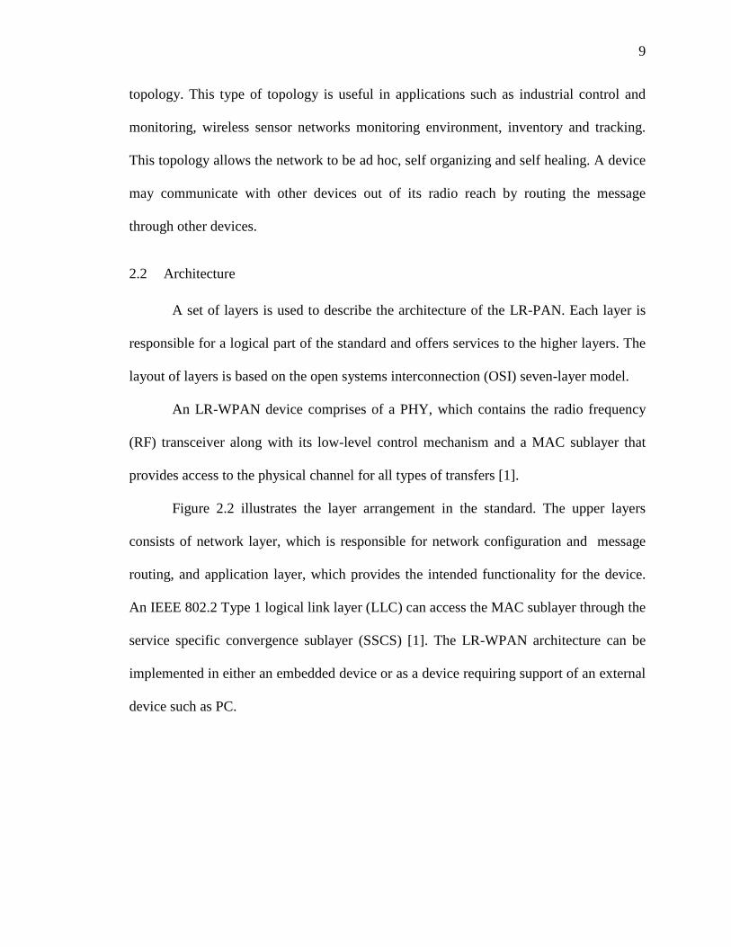
As illustrated in the Figure 4.2, the software is implemented in layers. The Media
Access Control (MAC) layer is the top layer and it provides a set of functions to
initialize, configure, control, send and receive packets of data over the radio. The MAC
layer on the Linux side maintains the state and configuration of the node. It
communicates with its counterpart on the microcontroller in the form of data packets.
Figure 4.2: Software structure and data flow
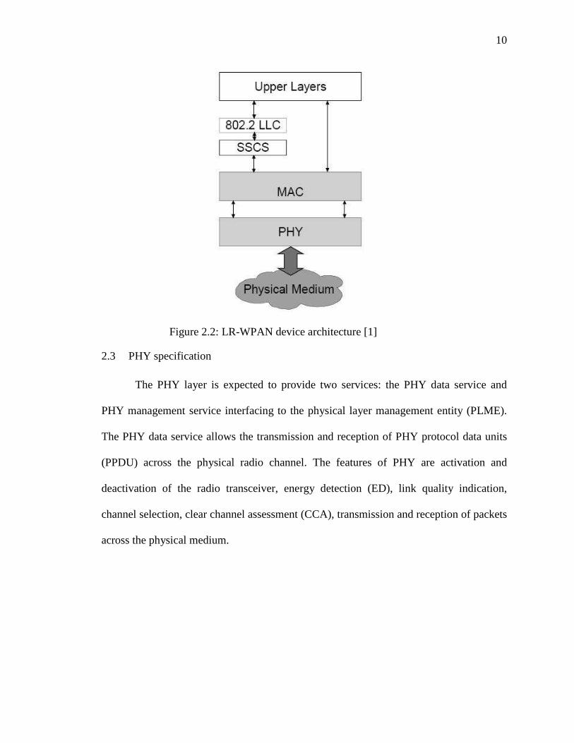
Figure 4.3: The structure of MAC packet
33
Figure 4.3 shows the structure of a MAC packet as composed of 3 fields. The first
field, “FrameID” identifies the type of packet and is of 2 bytes in length. The next field is
“Length”, a 1 byte field specifying the total length of the packet in bytes. The third field
“Data”, is the actual data, its length varies based on the type of packet. The largest
number for the “Length” field can be 255 and the header i.e. “FrameID” and “Length”
fields take 3 bytes, consequently a maximum of 252 bytes is available for the “Data”
field.
The MAC layer defines a function called MAC_Process(), which must be called
often. This function receives packets from SLIP and processes them accordingly. It is
best to place a call to this function in the infinite loop part of the software, if the software
is multi-threaded a separate thread can be assigned to execute this function periodically.
4.4.2 Linux – Serial Line Internet Protocol (SLIP)
The SLIP was designed to encapsulate IP datagram and send it over serial lines. It
encapsulates data to form frames so that the receiving end can differentiate the frames
and provide the data to the upper layers. SLIP protocol defines two special characters:
“END” (octal 300) and “ESC” (octal 333). To send a packet, a starting character of
“END “is sent first, it is followed by the data in the packet. If a data byte is the same code
as “END” character, a two byte sequence of “ESC” and octal 334 is sent instead. If it is
the same as an “ESC” character, a two byte sequence of “ESC” and octal 335 is sent
instead. After the entire data in the packet is sent, an “END” character is sent to end the
frame [9]. SLIP encapsulation drops corrupted packets, thus ensuring that the MAC layer
34
always receives a complete data packet. SLIP is a simple protocol and causes very less
overhead.
4.4.3 Linux – Serial port
Serial port access in Linux is fairly simple and easy. Each serial port on the
system is available as a “ttyS#” device file, # representing the port number, 0 for
“COM1”, 1 for “COM2” and so on. These files are located under “/dev” directory. The
configuration for the serial port is stored in a structure “termios” which is defined in the
header file “termios.h”. The “COM2” of the TS-7200 is connected to the CC2420DB,
which can be accessed by the device file “/dev/ttyAM1”. The serial port is configured for
sending and receiving of raw data bytes. The data can be sent and received via write()
and read() functions respectively. The reference [9], is a good guide for serial port
programming in Linux.
4.4.4 ATmega128L – MAC
This layer complements the Linux’s MAC layer with implementation of device
specific functionality. The MAC layer receives MAC frames from the SLIP layer and
processes them. When a 802.15.4 packet is received, it is wrapped with MAC frame and
sent to the Linux MAC layer through SLIP. This layer utilizes the sample code provided
by Chipcon to communicate with CC2420. The current stack code expects the
MAC_Process() function to be called in the infinite while loop of the microcontroller.
This function checks for a new 802.15.4 packet, processes it, it then checks for any new
frame in the SLIP layer to process.
35
The sample code consists of Hardware definition files, Hardware Abstraction
Layer (HAL) and Basic RF Library. The Hardware definition files define macros to the
registers in the microcontroller and CC2420, thus providing an easier way to access the
hardware. To support program development, hardware abstraction layer presents with
functions and macros to access most of the CC2420 and microcontroller resources. These
functions and macros can be used without hardware specific knowledge. The Basic RF
library provides simple function to send and receive 802.15.4 packets through CC2420.
4.4.5 ATmega128L – SLIP
The SLIP layer functionality is the same as in Linux’s SLIP layer. It encapsulates
every MAC frame being sent and unpacks every received frame and provides it to the
MAC layer. The current implementation buffers a single MAC frame received.
4.4.6 ATmega128L – Serial driver
The serial driver provides an interrupt based buffered mechanism for transmitting
and receiving data. It implements two circular buffers for transmission and reception. The
data being transmitted is copied to the transmit buffer and the transmit interrupt is
triggered. The transmit interrupt routine checks for an available data byte and copies it to
the transmit data register, if the transmit data buffer is empty, it disables further interrupt
triggers. When a byte of data is received in the microcontroller, it triggers the receive
interrupt routine which copies the data byte to receive buffer.
36
4.5 MAC Communication
Figure 4.4 illustrates the mechanism to send data from “Node 1” to “Node 2”. The
data packed into a MAC frame and wrapped with SLIP is sent from the TS7200 to the
CC2420DB. The microcontroller receives the frame and identifying as data to transmit,
sends it to CC2420 for transmission over radio. If the acknowledgement option was set,
the microcontroller waits for an acknowledgement from the other node before it times
out, If it receives an valid acknowledgement it forwards it to the Linux MAC else it sends
an transmission error.
Figure 4.4: Packet Transmission Mechanism
37
Figure 4.5 illustrates the packet reception. The “Node 2” sends a data packet
addressed to “Node 1”. Upon receiving it, the CC2420 interrupts the microcontroller. The
microcontroller gets the data from CC2420 buffer, if the packet requested
acknowledgement, it sends an acknowledgement to CC2420 for transmission. The
microcontroller then encapsulates the data with a MAC frame and sends it to the Linux
SBC.
Figure 4.5: Packet receiving mechanism
38
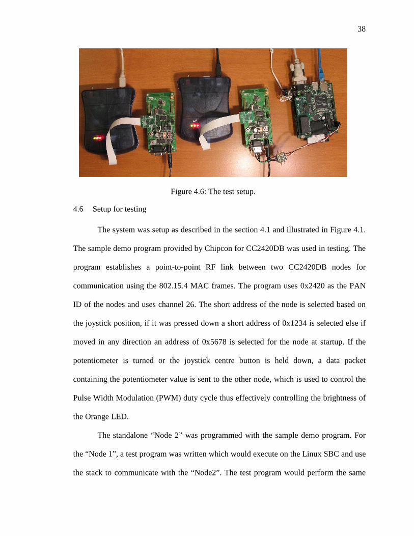
4.6 Setup for testing
The system was setup as described in the section 4.1 and illustrated in Figure 4.1.
The sample demo program provided by Chipcon for CC2420DB was used in testing. The
program establishes a point-to-point RF link between two CC2420DB nodes for
communication using the 802.15.4 MAC frames. The program uses 0x2420 as the PAN
ID of the nodes and uses channel 26. The short address of the node is selected based on
the joystick position, if it was pressed down a short address of 0x1234 is selected else if
moved in any direction an address of 0x5678 is selected for the node at startup. If the
potentiometer is turned or the joystick centre button is held down, a data packet
containing the potentiometer value is sent to the other node, which is used to control the
Pulse Width Modulation (PWM) duty cycle thus effectively controlling the brightness of
the Orange LED.
The standalone “Node 2” was programmed with the sample demo program. For
the “Node 1”, a test program was written which would execute on the Linux SBC and use
the stack to communicate with the “Node2”. The test program would perform the same
Figure 4.6: The test setup.
39
functionality as the demo program, but uses user inputs for the PWM duty cycle and
displays the contents on the received packets.
Figure 4.7 shows the menu system of the test program. Menu option 1 sends a
packet to “Node 2” with a user input value for the PWM duty cycle and the node address.
Upon receiving the packet “Node 2” would update the PWM duty cycle value and can be
noticed on the brightness of the LED. Other functions of the test program were tested
similarly by making appropriate changes on the demo program of “Node 2”.
Figure 4.7: Test program menu
Figure 4.8: A received frame by test program
40
Figure 4.8 shows the contents of a received packet on “Node1” from “Node 2”.
The test program displays the various fields associated with the packet received, it also
displays the raw bytes of the packet.
CHAPTER5: CONCLUSION
The objectives of the thesis work has been achieved with the implementation of
subset features of IEEE 802.15.4 features on a Linux SBC and demonstrate the use of
such a controller in LR-PAN. The SBC with Linux setup and the development tools form
the embedded Linux development system. The complete system with the hardware setup
and the software stack can be used in the following ways.
• Serves as an embedded Linux development system with the development tools,
other interfaces such as Ethernet and USB, and many applications.
• Can be used in investigating and developing upper layer protocols such as
ZigBee.
• Evaluating various aspects of IEEE 802.15.4 protocol.
• As a tool in the study of co-existence of IEEE 802.15.4 with other wireless
standards.
• As a packet logger/analyzer in IEEE 802.15.4 networks.
• As an educational tool in teaching LR-PAN and embedded Linux.
• As a valuable resource in the ongoing research of IEEE 802.15.4 at UNC
Charlotte.
42
5.1 Future work
This thesis work can be extended in many ways. The stack can be enhanced with
the support for beacon enabled networks. The current version lacks support for security
features, which can be implemented.
The stack can be ported to operating systems such as Windows CE, which is
another popular embedded operating system. As Windows CE is widely used in personal
digital assistants and cell phones, IEEE 802.15.4 wireless functionality can be added to
such devices.
REFERENCES
[1] Institute of Electrical and Electronic Engineers, Inc., ”IEEE Std. 802.15.4-2003, IEEE Standard for Information Technology – Telecommunications and Information Exchange between Systems – Local and Metropolitan Area Networks – specific Requirements – Part 15.4 : Wireless Medium Access Control (MAC) and Physical Layer (PHY) Specifications for Low Rate Wireless Personal Area Networks (LR-WPAN)” http://standards.ieee.org/getieee802/download/802.15.4-2003.pdf
[2] J.A. Gutierrez, “On the use of IEEE 802.15.4 to enable wireless sensor
networks in building automation” Proc.of IEEE Int. Conf. Personal, Indoor and Mobile Radio Communications (PIMRC’04), Barcelona, Spain September 2004, Vol 3 pp. 1865-1869.
[3] A. Sikora, V.F. Groza, “Coexistence of IEEE 802.15.4 with other Systems in
the 2.4 GHz- ISM-Band” Proc. of IEEE – Instrumentation and Measurement Technology Conference (IMTC’05), Ottawa, Canada May 2005, pp 1786-1791.
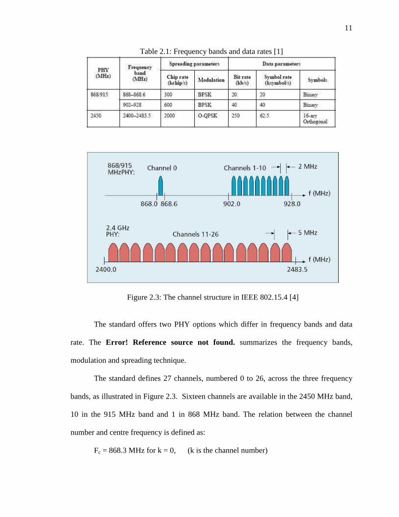
[4] E. Callaway, P. Gorday, L. Hester, J.A.Gutierrez, M. Naeve, B. Heile, V.Bahl
“Home Networking with IEEE 802.15.4: A Developing Standard for Low-Rate Wireless Personal Area Networks”, IEEE Communication Magazine, August 2002.
datasheet.pdf [9] G. Frerking, “Serial programming HOW TO”.
http://tldp.org/HOWTO/Serial-Programming-HOWTO/ [10] J. Romkey “RFC 1055 - Nonstandard for transmission of IP datagrams over
serial lines: SLIP” http://www.faqs.org/rfcs/rfc1055.html
44
[11] J. Lee, “ An Experiment on Performance Study of IEEE 802.15.4 Wireless Networks” Proc. of Emerging Technologies and Factory Automation, 2005 Volume 2, 19-22 Sept. 2005 Page(s):451-458
[12] A. Lennon, “Embedding Linux” IEE Review Volume 47, Issue 3, May 2001
Page(s):33 – 37
[13] D. Geer, “Survey: Embedded Linux Ahead of the Pack” Distributed Systems
Online, IEEE Volume 5, Issue 10, Oct. 2004 Page(s):3 – 3 [14] S. Hong, “Embedded Linux Outlook in the PostPC Industry” Proc. of Object-
[28] M. Galeev, “Home Networking with ZigBee” http://www.embedded.com/showArticle.jhtml?articleID=18902431
[29] A. H. Ansari “Hardware Development of an Embedded Wireless Evaluation
Board”, MS Thesis, University of North Carolina - Charlotte, Dec. 2005.
[30] R. Rai "IEEE 802.15.4 Protocol Implementation and Measurement of Current
Consumption", M.S Thesis, University of North Carolina- Charlotte, Dec. 2005.
[31] M. Marchesotti, M. Migliardi, R. Podesta, “A Measurement-Based Analysis of the Responsiveness of the Linux Kernel” Proc. of International Symposium and Workshop on Engineering of Computer Based Systems, 27-30 March 2006.
APPENDIX ATmega128L code /************************************************** ******* * File Name: MAC.h * * Version: 0.1 * * Author: Sandeep Sirpatil * * License: GNU General Public License.............. ..* * Purpose: This file contains constansta for MAC * * and function prototypes * * * *************************************************** ******/ #ifndef MAC_H #define MAC_H // Define Frame IDs #define MAC_SET_PAN_ID 1 #define MAC_GET_PAN_ID 2 #define MAC_SET_ADDR 3 #define MAC_GET_ADDR 4 #define MAC_SET_CHANNEL 5 #define MAC_GET_CHANNEL 6 #define MAC_SET_RECEIVER 7 #define MAC_GET_RECEIVER 8 #define MAC_XMIT_PACKET 9 #define MAC_RECV_PACKET 10 #define MAC_SET_ACK 11 #define MAC_GET_ACK 12 // FrameID + length + seqNum+SrcAdd+srcPanID+AckReq +Rssi+length // 2 + 1 + 1 + 2 + 2 + 1 + 1 + 1 = 11 #define MAC_RECV_PKT_OVERHEAD 11 int MAC_Init(); int MAC_Process(); #endif // MAC_H /************** END ***************************** *******/ /************************************************** ******* * File Name: MAC.c * * Version: 0.1 * * Author: Sandeep Sirpatil * * License: GNU General Public License.............. ..* * Purpose: This file implements the device specific * * functionality of IEEE 802.15.4 * * * *************************************************** ******/
47
#include "include.h" #include "SLIP.h" #include "MAC.h" #define SLIP_TX_BUF_SIZE 140 #define SLIP_RX_BUF_SIZE 140 // Structure for local copy of the received packet // This RX Struct will get written into when a pack et is received from radio. // This copy of the received packet should be used for further processing. volatile BASIC_RF_RX_INFO rf_rcv_info; UINT8 rf_rx_buffer[BASIC_RF_MAX_PAYLOAD_SIZE]; volatile UINT8 received_newFrame; UINT8 slip_TxBuff[SLIP_TX_BUF_SIZE]; UINT8 slip_RxBuff[SLIP_RX_BUF_SIZE]; BASIC_RF_TX_INFO rf_Tx_Info; UINT8 rf_Tx_Buffer[BASIC_RF_MAX_PAYLOAD_SIZE]; //extern volatile BASIC_RF_TX_INFO rf_Tx_Info; // Initialize function int MAC_Init(){ rf_rcv_info.pPayload = rf_rx_buffer; rf_Tx_Info.pPayload = rf_Tx_Buffer; received_newFrame = FALSE; return 0; } // Primarily handles packets to be received by SLIP and transmitted via radio. // and handle packets received via radio to be sent over SLIP. int mac_pr_ctr =0; int MAC_Process(){ UINT16 slipRxLength; int i=0; if(received_newFrame == TRUE){ // got a new frame from radio // Make a new SLIP frame and send it slip_TxBuff[0] = LOWER_BYTE(MAC_RECV_PACKET); slip_TxBuff[1] = UPPER_BYTE(MAC_RECV_PACKET); slip_TxBuff[2] = MAC_RECV_PKT_OVERHEAD + rf_rcv_info.length; slip_TxBuff[3] = rf_rcv_info.seqNumber;
48
slip_TxBuff[4] = LOWER_BYTE(rf_rcv_info.srcAddr); slip_TxBuff[5] = UPPER_BYTE(rf_rcv_info.srcAddr); slip_TxBuff[6] = LOWER_BYTE(rf_rcv_info.srcPanId) ; slip_TxBuff[7] = UPPER_BYTE(rf_rcv_info.srcPanId) ; slip_TxBuff[8] = rf_rcv_info.ackRequest; slip_TxBuff[9] = rf_rcv_info.rssi; slip_TxBuff[10] = rf_rcv_info.length; memcpy( &slip_TxBuff[MAC_RECV_PKT_OVERHEAD],rf_rcv_info.pPa yload,rf_rcv_info.length); //for (i=0; i< rf_rcv_info.length; i++){ // slip_TxBuff[MAC_RECV_PKT_OVERHEAD+i] = rf_rcv_info.pPayload[i]; // } SLIP_Send(slip_TxBuff, MAC_RECV_PKT_OVERHEAD+rf_rcv_info.length); mac_pr_ctr++; received_newFrame = FALSE; // clear flag } // check for new any frames received on SLIP and p rocess them SLIP_process(); if( SLIP_getFrame(slip_RxBuff, &slipRxLength) ==0) { // got a SLIP frame process it unsigned int frameId; frameId = GET_INT(slip_RxBuff[1], slip_RxBuf f[0]); switch(frameId){ case MAC_SET_PAN_ID :{ UINT8 n; UINT16 panid = GET_INT(slip_RxBuff[4],slip_RxBuff[3]); rfSettings.panId = panid; halRfWaitForCrystalOscillator(); DISABLE_GLOBAL_INT(); //FASTSPI_WRITE_RAM_LE(&myAddr, CC2420RAM_SHORTADDR, 2, n); FASTSPI_WRITE_RAM_LE(&panid, CC2420RAM_PANID , 2, n); ENABLE_GLOBAL_INT(); } break; case MAC_GET_PAN_ID: break; case MAC_SET_ADDR :{ UINT8 n; UINT16 addr = GET_INT(slip_RxBuff[4],slip_RxBuff[3]); rfSettings.myAddr = addr; halRfWaitForCrystalOscillator(); DISABLE_GLOBAL_INT();
49
FASTSPI_WRITE_RAM_LE(&addr, CC2420RAM_SHORTA DDR, 2, n); ENABLE_GLOBAL_INT(); } break; case MAC_GET_ADDR: break; case MAC_SET_CHANNEL: // check channel range 11-26 valid if( 10 < slip_RxBuff[3] && slip_RxBuff[3] <27){ DISABLE_GLOBAL_INT(); // if on turn it off if(rfSettings.receiveOn) FASTSPI_STROBE(CC2420_SRFOFF); halRfSetChannel(slip_RxBuff[3]); if(rfSettings.receiveOn) FASTSPI_STROBE(CC2420_SRXON); ENABLE_GLOBAL_INT(); } break; case MAC_GET_CHANNEL: break; case MAC_SET_RECEIVER: if(slip_RxBuff[3]==0){ // rx off basicRfReceiveOff(); //DISABLE_GLOBAL_INT(); //FASTSPI_STROBE(CC2420_SRFOFF); //ENABLE_GLOBAL_INT(); }else if(slip_RxBuff[3]==1){ // rx on basicRfReceiveOn(); //DISABLE_GLOBAL_INT(); //FASTSPI_STROBE(CC2420_SRXON); //ENABLE_GLOBAL_INT(); } break; case MAC_GET_RECEIVER: break; case MAC_XMIT_PACKET:{ // receive from sli p and send it via radio rf_Tx_Info.destAddr = GET_INT(slip_RxBuff[4],slip_RxBuff[3]); rf_Tx_Info.ackRequest = slip_RxBuff[5]; rf_Tx_Info.length = slip_RxBuff[6]; memcpy(rf_Tx_Info.pPayload, &slip_RxBuff[7],slip_RxBuff[6]); //basicRfSendPacket( rf_Tx_Info); if( basicRfSendPacket( &rf_Tx_Info) ){ //TODO: return status via SLIP TOGGLE_YLED();
50
}else{ TOGGLE_RLED(); } } break; case MAC_RECV_PACKET: break; } } return 0; } UINT16 rx_cntr =0; BASIC_RF_RX_INFO* basicRfReceivePacket(BASIC_RF_RX_ INFO *pRRI) { // int i=0; // Adjust the led brightness // PWM0_SET_DUTY_CYCLE(pRRI->pPayload[0]); // Blink the green LED // SET_GLED(); // halWait(10000); // CLR_GLED(); rf_rcv_info.seqNumber = pRRI->seqNumber; rf_rcv_info.srcAddr = pRRI->srcAddr; rf_rcv_info.srcPanId = pRRI->srcPanId; rf_rcv_info.length = pRRI->length; rf_rcv_info.ackRequest = pRRI->ackRequest; rf_rcv_info.rssi = pRRI->rssi; memcpy(rf_rcv_info.pPayload, pRRI->pPayload, pRRI- >length); received_newFrame = TRUE; TOGGLE_GLED(); rx_cntr++; // for(i=0; i<pRRI->length;i++){ // rf_rcv_info.pPayload[i]= pRRI->pPayload[i]; // } // Continue using the (one and only) reception structure return pRRI; } // basicRfReceivePacket /************** END ***************************** *******/
51
/************************************************** ******* * File Name: SLIP.h * * Version: 0.1 * * Author: Sandeep Sirpatil * * License: GNU General Public License.............. ..* * Purpose: This file contains SLIP configuration * * and function prototypes * * * *************************************************** ******/ #ifndef SLIP_H #define SLIP_H #define END 0300 /* indicates end of packet */ #define ESC 0333 /* indicates byte s tuffing */ #define ESC_END 0334 /* ESC ESC_END mean s END data byte */ #define ESC_ESC 0335 /* ESC ESC_ESC mean s ESC data byte */ int SLIP_Init(); int SLIP_Send(unsigned char *buf, int length); void SLIP_process(); int SLIP_getFrame(UINT8 *buf, UINT16 *size); #endif // SLIP_H /************** END ***************************** *******/ /************************************************** ******* * File Name: SLIP.c * * Version: 0.1 * * Author: Sandeep Sirpatil * * License: GNU General Public License.............. ..* * Purpose: This file implements SLIP layer and * * uses UART layer as serial driver * * * *************************************************** ******/ #include <include.h> #include "USART.h" #include "SLIP.h" #define SLIP_TXBUF_SIZE 200 #define SLIP_RXBUF_SIZE 250 UINT8 slip_xmit_buf[SLIP_TXBUF_SIZE]; UINT8 rx_lastByte;
// check the frame status if(slip_rcv_frame.isEmpty == FALSE){ // containe a new frame. // If new frame is available, copy the data and cl ear the receiveframe for(i=0;i<slip_rcv_frame.length; i++){ buf[i] = slip_rcv_frame.buffer[i]; } *size = slip_rcv_frame.length; slip_rcv_frame.isEmpty = TRUE; return 0; }else{ // If no new frame avialable retunr -1 return -1; } } /* This function is to be called as many times as p ossible. It checks the receiveframe, if found empty, it tri es to get data from the USART layer and assemble a new frame.*/ void SLIP_process(){ UINT8 ch; int moredata =1; if(slip_rcv_frame.isEmpty == TRUE){ if(slip_rcv_frame.writeFlag == FALSE){ // begi nning of a new frame slip_rcv_frame.length = 0; } while(moredata == TRUE){ // a getdata flag if(USART1_Recv(&ch) ==0){ // if a byte is received then process it switch(ch){ case END: if(slip_rcv_frame.writeFlag == FALSE){ //start of new frame slip_rcv_frame.writeFlag = TRUE; // indicate the write is in progress }else{ // End of frame receive d. slip_rcv_frame.isEmpty = F ALSE; // indicate a new frame is stored. slip_rcv_frame.writeFlag = FALSE; moredata = FALSE; // end t he while loop } break; case ESC:
54
rx_lastByte = ESC; // keep a r ecord of it break; case ESC_END: if(rx_lastByte == ESC){ slip_rcv_frame.buffer[slip_rcv_frame.length] = END; slip_rcv_frame.length++; rx_lastByte = 0; }else{ // TODO: handle error } break; case ESC_ESC: if(rx_lastByte == ESC){ slip_rcv_frame.buffer[slip_rcv_frame.length] = ESC; slip_rcv_frame.length++; rx_lastByte = 0; }else{ // TODO: handle error } break; default: slip_rcv_frame.buffer[slip_rcv _frame.length] = ch; slip_rcv_frame.length++; } }else{ // no more data in Queue moredata = FALSE; } } // while } } /************** END ***************************** *******/ /************************************************** ******* * File Name: USART.h * * Version: 0.1 * * Author: Sandeep Sirpatil * * License: GNU General Public License.............. ..* * Purpose: Provides varios configuration options fo r * * UART driver. * * * *************************************************** ******/ #ifndef USART_H #define USART_H //#define USART_2XMODE 1; // Puts USART in 2x mod e. not preferred. #ifdef USART_2XMODE // (CPUCLOCK / 8*baud) -1 #define UART_BAUD_2K4 416
/************************************************** ******* * File Name: SLIP.h * * Version: 0.1 * * Author: Sandeep Sirpatil * * License: GNU General Public License.............. ..* * Purpose: This file contains SLIP configuration * * and function prototypes * * * *************************************************** ******/ #ifndef SLIP_H #define SLIP_H /* SLIP definitions */ #define END 0300 /* indicates end of packet 0xC0 */ #define ESC 0333 /* indicates byte s tuffing 0xDB */ #define ESC_END 0334 /* ESC ESC_END mean s END data byte 0xDC */ #define ESC_ESC 0335 /* ESC ESC_ESC mean s ESC data byte 0xDD */ #define SLIP_TX_BUFF_SIZE 250 #define SLIP_RX_BUFF_SIZE 500 #define FRAME_SIZE 250 /* Serial port definitions */ #define BAUD_RATE B9600 //#define BAUD_RATE B57600 //#define BAUD_RATE B115200 //#define BAUD_RATE B230400 #define PORT "/dev/ttyAM1" /* Function declerations*/ int SLIP_Init(); int SLIP_Term(); int SLIP_Process(); int SLIP_Send(unsigned char *buf, int len); int SLIP_Recv(unsigned char *buf,int *length); #endif //SLIP_H /************** END ***************************** *******/ /************************************************** ******* * File Name: SLIP.c * * Version: 0.1 * * Author: Sandeep Sirpatil * * License: GNU General Public License.............. ..* * Purpose: This file implements SLIP Layer * * * * * *************************************************** ******/ /* The file contains the code to interface to the s erial port
65
and send and receive SLIP frames*/ #include "include.h" // Receive Circular buffer static int rx_rdIdx =0; static int rx_wrIdx = 0; static unsigned char rx_buffer[SLIP_RX_BUFF_SIZE]; static unsigned char rx_lastByte; struct rxFrame{ unsigned char buffer[FRAME_SIZE]; int length; int isEmpty; int writeFlag; }; struct rxFrame rx_frame; struct termios oldconfig, newconfig; int fd; /* Function definitions of local functions */ int port_Open(); int port_Close(); int rx_putByte( char c); int rx_getByte(unsigned char *c); int SLIP_Init(){ rx_frame.isEmpty = TRUE; rx_frame.writeFlag = FALSE; rx_frame.length =0; fd = 0; return (port_Open()); } int SLIP_Term(){ return (port_Close()); } int port_Open(){ int ret; /* O_NOCTTY - this is not the controlling termi nal program else Cntr-C will close process */ /* O_NDELAY or O_NONBLOCK - Do not care abt DC D line status and non blocking read*/ //fd = open("/dev/ttyAM1", O_RDWR | O_NOCTTY | O_NDELAY); fd = open(PORT, O_RDWR | O_NOCTTY | O_NDELAY); if(fd == -1){ return -1; // port open failed } tcgetattr(fd, &oldconfig); // save the old conf ig
66
tcgetattr(fd, &newconfig); // Set the port speed parameters cfsetispeed(&newconfig, BAUD_RATE); cfsetospeed(&newconfig, BAUD_RATE); // 8N1 newconfig.c_cflag &= ~PARENB; newconfig.c_cflag &= ~CSTOPB; newconfig.c_cflag &= ~CSIZE; newconfig.c_cflag |= CS8; newconfig.c_cflag &= ~CRTSCTS; // No Flow contr ol newconfig.c_cflag |= (CLOCAL | CREAD); // local line no ownew change and enable receiver // set line parameters for raw input; ie no pro cessing newconfig.c_lflag &= ~(ICANON |ECHO|ECHOE| ISIG ); // Input flags newconfig.c_iflag &= ~(IXON|IXOFF |IXANY); // Output flags newconfig.c_oflag &= ~OPOST; // raw output // set the new options to the port ret = tcsetattr(fd, TCSANOW, &newconfig); return 0; } int port_Close(){ //restore old port settinngs if(fd!=0 && fd!=-1){ tcsetattr(fd, TCSANOW, &oldconfig); close(fd); fprintf(stderr,"Port closed\n"); return 0; // test } return -1; } /* Max packet size is about 150 bytes sends a packet through the serial port frammed in slip protocol */ int SLIP_Send(unsigned char *buf, int len){ unsigned char slipBuff[SLIP_TX_BUFF_SIZE]; int idx=0; int i; /* send an initial END character to flush out any data that may * have accumulated in the receiver due to lin e noise */ slipBuff[idx] = END; idx++; for( i =0; i<len ;i++){ if(idx+2 > SLIP_TX_BUFF_SIZE){ return -1; // buffer overflow }
67
switch(buf[i]){ // data equals END, then send ESC follo wed by END case END: slipBuff[idx] = ESC; idx++; slipBuff[idx] = ESC_END; idx++; break; case ESC: slipBuff[idx] = ESC; idx++; slipBuff[idx] = ESC_ESC; idx++; break; default: slipBuff[idx] = buf[i]; idx++; } } slipBuff[idx] = END; // end of frame idx++; //printBuf(slipBuff,10); // debug if(idx == write(fd,slipBuff,idx)){ fprintf(stderr,"write succ\n"); return 0; // write success }else { return -1; // write failure } } int SLIP_Recv(unsigned char *buf,int *length){ int i; if(rx_frame.isEmpty ==FALSE){ for(i=0;i<rx_frame.length;i++){ buf[i] = rx_frame.buffer[i]; } *length = rx_frame.length; rx_frame.isEmpty = TRUE; }else{ return -1; // no new frame } return 0; } /* Serial receive Queue management functions */ int rx_putByte( char c){ if(rx_wrIdx+1 ==rx_rdIdx || (rx_wrIdx+1 == SLIP _RX_BUFF_SIZE && !rx_rdIdx)) { return -1; // Queue full } rx_buffer[rx_wrIdx] = c; rx_wrIdx++; if(rx_wrIdx ==SLIP_RX_BUFF_SIZE){
68
rx_wrIdx =0; } return 0; } int rx_getByte(unsigned char *c){ if(rx_rdIdx == SLIP_RX_BUFF_SIZE){ rx_rdIdx = 0; // reset it } if(rx_rdIdx == rx_wrIdx){ return -1; // Queue empty } rx_rdIdx++; *c = rx_buffer[rx_rdIdx -1]; return 0; } // Should be called periodically to process the inp ut buffer int SLIP_Process(){ unsigned char buffer[50],ch; int rtn=0, i=0; int moredata = 1; rtn = read(fd, &buffer, 50); //printf("Slip read return %d ",rtn); //fprintf(stderr,"f-Slip read return "); if(rtn >0){ for(i=0; i<rtn; i++){ rx_putByte(buffer[i]); // TODO: need to take care of Queue ful l condition } } // check the current frame status, if empty, lo ad new frame if(rx_frame.isEmpty == TRUE){ if(rx_frame.writeFlag == FALSE){ // beginni ng of a new frame rx_frame.length = 0; } while(moredata == TRUE){ // a getdata flag if(rx_getByte(&ch) ==0){ // if a byte i s received then process it switch(ch){ case END: if(rx_frame.writeFlag ==FAL SE){ //start of new frame rx_frame.writeFlag = TR UE; // indicate the write is in progress }else{ // End of frame rece ived. rx_frame.isEmpty = FALS E; // indicate a new frame is stored. rx_frame.writeFlag = FA LSE; moredata = FALSE; // en d the while loop //fprintf(stderr,"slip got a frame\n"); }
69
break; case ESC: rx_lastByte = ESC; // keep a record of it break; case ESC_END: if(rx_lastByte == ESC){ rx_frame.buffer[rx_fram e.length] = END; rx_frame.length++; rx_lastByte = 0; }else{ // TODO: handle erro r } break; case ESC_ESC: if(rx_lastByte == ESC){ rx_frame.buffer[rx_fram e.length] = ESC; rx_frame.length++; rx_lastByte = 0; }else{ // TODO: handle erro r } break; default: rx_frame.buffer[rx_frame.le ngth] = ch; rx_frame.length++; } }else{ // no more data in Queue moredata = FALSE; } } // while } return 0; } /************** END ***************************** *******/ /************************************************** ******* * File Name: util.h * * Version: 0.1 * * Author: Sandeep Sirpatil * * License: GNU General Public License.............. ..* * Purpose: This file contains utility macros * * and function prototypes * * * *************************************************** ******/ #ifndef UTIL_H #define UTIL_H #define LOWER_BYTE(x) ((unsigned char)(x & 0xFF)) #define UPPER_BYTE(x) ((unsigned char)((x & 0xFF00) >>8)) // x- MSB y-LSB #define GET_INT(x,y) ((((unsigned char)x)<<8) |((u nsigned char)y)) void printBuf(unsigned char *buf, int len); void clearBuf(unsigned char *buf, int len);
70
void printPacket(unsigned char *buf, int len); #endif /************** END ***************************** *******/ /* ************************************************ ******* * File Name: SLIP.h * * Version: 0.1 * * Author: Sandeep Sirpatil * * License: GNU General Public License.............. ..* * Purpose: This file utility functions * * * * * *************************************************** ******/ #include "include.h" /* Printf the contenets of buffer in Hex to stderr* / void printBuf(unsigned char *buf, int len){ int i; fprintf(stderr,"# "); for(i=0; i<len; i++){ fprintf(stderr,"%02X ", buf[i]); } fprintf(stderr," ::"); } void clearBuf(unsigned char *buf, int len){ int i=0; for(i=0;i<len;i++){ buf[i] = 0; } } void printPacket(unsigned char *buf, int len){ unsigned int frameId; frameId = GET_INT(buf[1], buf[0]); switch(frameId){ case MAC_SET_PAN_ID : break; case MAC_GET_PAN_ID: break; case MAC_SET_ADDR : break; case MAC_GET_ADDR: break; case MAC_SET_CHANNEL: break; case MAC_GET_CHANNEL: break; case MAC_SET_RECEIVER: break; case MAC_GET_RECEIVER: break; case MAC_XMIT_PACKET: break;
71
case MAC_RECV_PACKET: fprintf(stderr,"\n Packet Received:\n") ; fprintf(stderr," Frame Id : MAC_RECV_PA CKET %04X\n",frameId); fprintf(stderr," Frame Length: %u\n",bu f[2]); fprintf(stderr," Frame Seq num: %u\n",b uf[3]); fprintf(stderr," Frame SrcAddr: %04X\n",GET_INT(buf[5],buf[4])); fprintf(stderr," Frame SrcPANId: %04X\n",GET_INT(buf[7],buf[6])); fprintf(stderr," Frame ACK Request: %02 X\n", buf[8]); fprintf(stderr," Frame RSSI: %d\n", buf [9]); fprintf(stderr," Frame Pkt Length: %u\n ",buf[10]); printBuf(&buf[11],buf[10]); fprintf(stderr," End of Frame::\n"); break; case MAC_SET_ACK: break; case MAC_GET_ACK: break; default: fprintf(stderr," Case fail in func \"pr intPacket\" \n"); } } /************** END ***************************** *******/ /************************************************** ******* * File Name: include.h * * Version: 0.1 * * Author: Sandeep Sirpatil * * License: GNU General Public License.............. ..* * Purpose: A general include file for the whole * * application * * * *************************************************** ******/ #ifndef INCLUDE_H #define INCLUDE_H // general definitions used in the stack #include <sys/types.h> #include <sys/stat.h> #include <fcntl.h> #include <termios.h> #include <stdio.h> #include <signal.h> #include <unistd.h> #include <stdlib.h> #include <errno.h> #include "util.h" #include "SLIP.h" #include "MAC.h"